EP2512571B1 - Cuffless tracheal tube - Google Patents
Cuffless tracheal tube Download PDFInfo
- Publication number
- EP2512571B1 EP2512571B1 EP10795868.8A EP10795868A EP2512571B1 EP 2512571 B1 EP2512571 B1 EP 2512571B1 EP 10795868 A EP10795868 A EP 10795868A EP 2512571 B1 EP2512571 B1 EP 2512571B1
- Authority
- EP
- European Patent Office
- Prior art keywords
- eap
- tracheal tube
- tubular body
- ventilating device
- change
- Prior art date
- Legal status (The legal status is an assumption and is not a legal conclusion. Google has not performed a legal analysis and makes no representation as to the accuracy of the status listed.)
- Not-in-force
Links
Images



Classifications
-
- A—HUMAN NECESSITIES
- A61—MEDICAL OR VETERINARY SCIENCE; HYGIENE
- A61M—DEVICES FOR INTRODUCING MEDIA INTO, OR ONTO, THE BODY; DEVICES FOR TRANSDUCING BODY MEDIA OR FOR TAKING MEDIA FROM THE BODY; DEVICES FOR PRODUCING OR ENDING SLEEP OR STUPOR
- A61M16/00—Devices for influencing the respiratory system of patients by gas treatment, e.g. ventilators; Tracheal tubes
- A61M16/04—Tracheal tubes
-
- A—HUMAN NECESSITIES
- A61—MEDICAL OR VETERINARY SCIENCE; HYGIENE
- A61M—DEVICES FOR INTRODUCING MEDIA INTO, OR ONTO, THE BODY; DEVICES FOR TRANSDUCING BODY MEDIA OR FOR TAKING MEDIA FROM THE BODY; DEVICES FOR PRODUCING OR ENDING SLEEP OR STUPOR
- A61M16/00—Devices for influencing the respiratory system of patients by gas treatment, e.g. ventilators; Tracheal tubes
- A61M16/04—Tracheal tubes
- A61M16/0434—Cuffs
- A61M16/0443—Special cuff-wall materials
-
- A—HUMAN NECESSITIES
- A61—MEDICAL OR VETERINARY SCIENCE; HYGIENE
- A61M—DEVICES FOR INTRODUCING MEDIA INTO, OR ONTO, THE BODY; DEVICES FOR TRANSDUCING BODY MEDIA OR FOR TAKING MEDIA FROM THE BODY; DEVICES FOR PRODUCING OR ENDING SLEEP OR STUPOR
- A61M16/00—Devices for influencing the respiratory system of patients by gas treatment, e.g. ventilators; Tracheal tubes
- A61M16/04—Tracheal tubes
- A61M16/0463—Tracheal tubes combined with suction tubes, catheters or the like; Outside connections
-
- A—HUMAN NECESSITIES
- A61—MEDICAL OR VETERINARY SCIENCE; HYGIENE
- A61M—DEVICES FOR INTRODUCING MEDIA INTO, OR ONTO, THE BODY; DEVICES FOR TRANSDUCING BODY MEDIA OR FOR TAKING MEDIA FROM THE BODY; DEVICES FOR PRODUCING OR ENDING SLEEP OR STUPOR
- A61M16/00—Devices for influencing the respiratory system of patients by gas treatment, e.g. ventilators; Tracheal tubes
- A61M16/04—Tracheal tubes
- A61M16/0434—Cuffs
-
- A—HUMAN NECESSITIES
- A61—MEDICAL OR VETERINARY SCIENCE; HYGIENE
- A61M—DEVICES FOR INTRODUCING MEDIA INTO, OR ONTO, THE BODY; DEVICES FOR TRANSDUCING BODY MEDIA OR FOR TAKING MEDIA FROM THE BODY; DEVICES FOR PRODUCING OR ENDING SLEEP OR STUPOR
- A61M16/00—Devices for influencing the respiratory system of patients by gas treatment, e.g. ventilators; Tracheal tubes
- A61M16/04—Tracheal tubes
- A61M16/0488—Mouthpieces; Means for guiding, securing or introducing the tubes
-
- A—HUMAN NECESSITIES
- A61—MEDICAL OR VETERINARY SCIENCE; HYGIENE
- A61M—DEVICES FOR INTRODUCING MEDIA INTO, OR ONTO, THE BODY; DEVICES FOR TRANSDUCING BODY MEDIA OR FOR TAKING MEDIA FROM THE BODY; DEVICES FOR PRODUCING OR ENDING SLEEP OR STUPOR
- A61M2205/00—General characteristics of the apparatus
- A61M2205/02—General characteristics of the apparatus characterised by a particular materials
- A61M2205/0272—Electro-active or magneto-active materials
- A61M2205/0283—Electro-active polymers [EAP]
Definitions
- the present disclosure relates generally to medical devices and, more particularly, to airway devices, such as tracheal tubes.
- a tube or other medical device may be used to control the flow of air, food, fluids, or other substances into the patient.
- medical devices such as tracheal tubes
- tracheal tubes may include endotracheal tubes (ETTs), tracheotomy tubes, or transtracheal tubes.
- ETTs endotracheal tubes
- tracheotomy tubes or transtracheal tubes.
- a high-quality seal against the tracheal passageway allows a ventilator to perform efficiently.
- tracheal tubes are available in a range of sizes from which doctors may select the closest approximate size for a particular patient.
- the differences between tube sizes may generally reflect both differences in the length of the tube as well as different tube diameters.
- doctors may wish to select a tracheal tube with an appropriate diameter in order to allow the tube to be easily inserted into the patient while providing the largest possible airway path for respiratory gases.
- a tracheal tube with too small a tube diameter may result in a high pressure drop during breathing or ventilation.
- a tracheal tube with too large a tube diameter can become difficult to navigate through the larynx and trachea, possibly increasing the time required to intubate the patient.
- a large tracheal tube can prove somewhat uncomfortable for the patient. For instance, irritation of the tracheal walls can result from increased contact with the tracheal tube.
- US 2009/159085 describes a medical device including an inflation cuff composed of piezoelectric polymers. Upon inflation of the inflation cuff, the piezoelectric polymers of the inflation cuff exhibit an electrical potential that is measured and correlated to an inflation cuff pressure. The pressure is then adjusted as necessary to prevent sustained underinflation or overinflation of the inflation cuff.
- a tracheal tube ventilating device may be used to seal an airway of a patient and provide positive pressure to the lungs when properly positioned in a trachea.
- the ventilating gas passing through the tube typically comprises air, but may also include anesthetic gases, medications, or various gas mixtures, such as mixtures containing higher concentrations of oxygen than atmospheric air.
- the source of the ventilating gas is typically a medical device such as a ventilator.
- a clinician guides the tube through the upper respiratory tract and past the vocal cords. This opening is typically smaller than the inner diameter of the trachea.
- an outer diameter of the tube is minimized during intubation or extubation.
- the tube outer diameter is increased enough to create a seal with the inner surface of the trachea.
- the tube inner diameter may be increased to provide less resistance to the flow of gas.
- Electroactive polymers are polymers having shapes that can be modified when an electric potential is applied to them. EAPs are generally divided into two categories: dielectric EAPs and ionic EAPs. Activation of dielectric EAPs occurs when electrostatic forces are created between two electrodes.
- the present techniques contemplate the use of ionic EAPs, which require electric potentials of only a few volts and electric currents in the range of a few microamps or milliamps, making them ideally suited for use in humans.
- ionic EAPs are biocompatible. Ionic EAPs swell and contract based on the movement of ions and water molecules into or out of the polymer.
- devices comprising EAP can configured in a variety of ways to accomplish needed changes in volume, length, and/or diameter of the tube or a portion of the tube.
- An EAP may be selected that undergoes a clinically effective change in volume, thickness, or both upon application of an electrical potential. For example, an EAP may undergo a change in volume, thickness, or both of at least approximately 20%. In other embodiments, the increase may be at least approximately 30%.
- Using such an EAP in a tracheal tube enables a tube to be designed that has a minimal outside diameter during intubation or extubation and an increased outside diameter sufficient to create a seal once properly positioned in the trachea.
- the inside diameter of the tube may also be increased subsequent to intubation to ease the flow of gases during patient ventilation. Further, as the outer walls of the tube may contact the trachea over its length, the length of the seal may be increased to provide improved sealing.
- EAP will maintain its shape or volume as long as the proper electrical potential is maintained.
- tracheal tubes comprising EAP
- an entire portion of the tracheal tube may comprise EAP.
- a layer of EAP may be disposed over the tube.
- Other configurations are possible as well.
- the clinician has the capability of adjusting the various dimensions of the tube to facilitate intubation and extubation, maintain a proper seal, provide maximum ventilation, and enhance patient comfort.
- the disclosed tracheal tubes, systems, and methods may be used in conjunction with any appropriate medical device, including without limitation a feeding tube, an ETT, a tracheotomy tube, a circuit, an airway accessory, a connector, an adapter, a filter, a humidifier, a nebulizer, nasal cannula, or a supraglottic mask/tube.
- the present techniques may also be used to treat any patient benefiting from mechanical ventilation, e.g., positive pressure ventilation.
- the devices and techniques provided herein may be used to treat human patients, such as trauma victims, patients with tracheotomies, anesthetized patients, cardiac arrest victims, patients suffering from airway obstructions, and patients suffering from respiratory failure.
- FIG. 1 is a perspective view of an embodiment of an ETT 10 with a tip comprising an EAP in an unexpanded state.
- the ETT 10 comprises a tubular body 12.
- the tubular body 12 comprises a proximal end 18 and a distal end 20.
- the tubular body 12 comprises a first material, a second material, and a transition region joining the two materials.
- the first material used for the proximal end 18 of the tubular body 12 may be selected from materials commonly used for ETTs, such as polyvinyl chloride (PVC).
- PVC polyvinyl chloride
- a transition 14 to the EAP tip begins near the middle or distal end 20 of the tubular body 12.
- the transition 14 comprises a region where the first material used for the proximal end 18 of the tubular body 12 is gradually replaced by the EAP.
- the second material used for the EAP section 16 of the tubular body 12 comprises substantially all EAP and almost none of the first material, although various mixtures of the materials that still provide the desired shape-changing properties may be employed.
- EAPs include, but are not limited to, polypyrroles, polyanilines, polythiphenes, polyethylenedisoxythiophenes, or mixtures thereof. Such EAPs are capable of undergoing a clinically effective change in volume, thickness, or both upon application of an electrical potential.
- the transition 14 comprises a proximal side 22 and a distal side 24.
- the distal side is positioned towards the lower respiratory tract, while the proximal side is oppositely oriented.
- the ETT 10 may include a suction lumen 26 to remove secretions that may reside above the EAP section 16 during use.
- at least one electrical conductor 28 couples the EAP section 16 to a source of electrical potential.
- the electrical conductor 28 may comprise a pair of insulated wires extending from the source of electrical potential, passing through a lumen of the tubular body 12, and emerging in the EAP as the bare ends of the wires, or small terminal plates or electrodes.
- sources of electrical potential include, but are not limited to, batteries, power supplies, wall current, generators, etc.
- the electrical conductor 28 may comprise a plug or other adaptor to enable it to be connected to the source of electrical potential.
- the electrical potential applied to the EAP may be between approximately 1 to 2 volts. Depending on the EAP and the direction of electric current, the electrical potential may act to expand or collapse the EAP.
- Dimensions of the ETT 10 include an outside diameter 30 of the tubular body 12 at the proximal end 18.
- the outside diameter 30 at the proximal end 18 may be between approximately 2 and 16 mm.
- the tubular body 12 near the proximal end 18 comprises an inside diameter 32.
- the inside diameter 32 near the proximal end 18 may be between approximately 1.5 and 12 mm.
- a wall thickness 34 of the tubular body 12 may be between approximately 0.5 to 2 mm.
- the EAP section 16 also comprises an unexpanded outside diameter 36, an inside diameter 38, and an unexpanded wall thickness 40.
- the dimensions of the EAP section 16 when unexpanded may be substantially the same as the dimensions of the proximal end 18 of the tubular body 12.
- the EAP section 16 may comprise a length 42 configured to be long enough to allow the EAP section 16 to create a sufficient seal against the trachea wall.
- the EAP length 42 may be between approximately 8 and 50 mm.
- the transition 14 may comprise a length 43 configured to be long enough to enable standard tube manufacturing techniques to transition from the first material to the second material in as short a distance as possible. In certain embodiments, the transition length 43 may be between approximately 10 and 20 mm.
- FIG. 2 is a perspective view of an embodiment of an ETT 10 with a tip comprising an EAP in an expanded state.
- the expanded EAP section 16 comprises an outside diameter 44, a wall thickness 46, and a length 48.
- the expanded outside diameter 44 may be between approximately 8 and 55 mm.
- the expanded outside diameter 44 of the EAP section 16 may be at least approximately 20% greater than the unexpanded diameter 36 of the EAP section 16 .
- the increase may be at least approximately 30%.
- the expanded outside diameter 44 is configured to be large enough to allow the EAP section 16 to create an effective seal against the trachea wall.
- the expanded wall thickness 46 of the EAP section 16 may be between approximately 2 and 8 mm.
- the expanded length 48 of the EAP section 16 may be between approximately 8 and 55 mm.
- the transition 14 comprises some EAP, it may expand an amount less than the EAP section 16 .
- the inside diameter 38 of the EAP section 16 remains the same in the expanded state, as substantially all of the expansion of the EAP in this embodiment is directed outward.
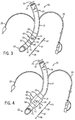
- FIG. 3 is a perspective view of an embodiment of an ETT 50 with an EAP middle section 16 in an unexpanded state.
- the body comprises two transition sections: a proximal transition 14 and a distal transition 51.
- the distal transition 51 comprises a proximal side 53 and a distal side 54.
- the distal transition 51 comprises a length 56.
- the distal transition length 56 may be the same as the proximal transition length 43, such as between approximately 10 and 20 mm.
- the tubular body 12 comprises a distal tip 52 that does not comprise EAP.
- the non-EAP distal tip 52 may be comprised of the same or similar materials as the proximal end of the tubular body 12, such as, but not limited to PVC.
- the non-EAP distal tip 52 comprises a length 58 that may be configured to be long enough such that the EAP section 16 is located an anatomically relevant distance from the distal end of the tubular body 12.
- the length 58 of the non-EAP distal tip 52 may be between approximately 3 and 20 mm. Other elements shown in FIG. 3 in common with those shown in FIG. 1 are discussed above.
- FIG. 4 is a perspective view of an embodiment of an ETT 50 with an EAP middle section 16 in an expanded state.
- the expanded EAP section 16 comprises an outside diameter 60, a wall thickness 62, and a length 64.
- the expanded outside diameter 60 may be between approximately 8 and 55 mm.
- the expanded outside diameter 60 of the EAP section 16 may be at least approximately 20% greater than the unexpanded diameter 36 of the EAP section 16 .
- the increase may be at least approximately 30%.
- the expanded outside diameter 60 is configured to be large enough to allow the EAP section 16 to create an effective seal against the trachea wall.
- the expanded wall thickness 62 of the EAP section 16 may be between approximately 2 and 8 mm.
- the expanded length 64 of the EAP section 16 may be between approximately 8 and 55 mm.
- the proximal transition 14 and the distal transition 51 both comprise some EAP, they may expand an amount less than the EAP section 16.
- the inside diameter 38 of the EAP section 16 remains the same in the expanded state, as substantially all of the expansion of the EAP in this embodiment is directed outward.
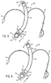
- FIG. 5 is a perspective view of an embodiment of an ETT 66 with an outer layer of EAP 68 in an unexpanded state disposed over the tubular body 12.
- the EAP layer 68 comprises a thickness 70, configured to be small enough to enable the ETT 66 to be easily intubated or extubated.
- the thickness 70 of the EAP layer 68 may be between approximately 0.5 to 1 mm.
- An interface 71 exists where the EAP layer 68 begins on the tubular body 12. Other elements shown in FIG. 5 in common with those shown in FIG. 1 are discussed above.
- FIG. 6 is a perspective view of an embodiment of an ETT 66 with an EAP layer 68 in an expanded state.
- the expanded EAP layer 68 comprises a wall thickness 72 and an outside diameter 73.
- the expanded wall thickness 72 of the EAP layer 68 may be between approximately 2 and 8 mm.
- the expanded outside diameter 73 of the EAP layer 68 may be between approximately 8 and 55 mm.
- the expanded outside diameter 73 of the EAP layer 68 may be at least approximately 20% greater than the unexpanded diameter 36 of the EAP layer 68.
- the increase may be at least approximately 30%.
- the expanded outside diameter 73 is configured to be large enough to allow the EAP layer 68 to create an effective seal against the trachea wall.
- Other elements shown in FIG. 6 in common with those shown in FIG. 5 are discussed above.
- FIG. 7 is a perspective view of an embodiment of a tracheostomy tube 74 with an EAP middle section 82 in an unexpanded state.
- the tube 74 comprises a proximal end 76 and a distal end 78. Because the EAP section 82 is in the middle of the tube 74, the tube comprises two transition sections: a proximal transition 80 and a distal transition 84.
- the proximal transition 80 comprises a length 81 and the distal transition comprises a length 85.
- the proximal transition length 81 and the distal transition length 85 may be the same, such as between approximately 10 and 20 mm.
- the proximal transition 80 comprises a proximal side 88 and a distal side 90.
- the distal transition 84 comprises a proximal side 92 and a distal side 94.
- the EAP section 82 comprises a length 83. In certain embodiments, the EAP length 83 may be between approximately 8 and 55 mm.
- the tube 74 comprises a distal tip 86 that does not comprise EAP. Instead, the non-EAP distal tip 86 may be comprised of the same or similar materials as the proximal end of the tube 74, such as, but not limited to PVC.
- the non-EAP distal tip 86 comprises a length 87 that may be configured to be long enough such that the EAP section 82 is located an anatomically relevant distance from the distal end of the tube 74.
- the length 87 of the non-EAP distal tip 86 may be approximately 3 and 20 mm.
- Other elements of the tube 74 include at least one electrical conductor 96 that couples the EAP section 82 to a source of electrical potential.
- the electrical potential applied to the EAP may be between approximately 1 to 2 volts.
- Dimensions of the tube 74 near the proximal end 76 include an outside diameter 97, an inside diameter 98, and a wall thickness 100.
- the outside diameter 97 at the proximal end 18 may be between approximately 2 and 16 mm
- the inside diameter 98 may be between approximately 1.5 and 12 mm
- the wall thickness 100 may be between approximately 0.5 and 2 mm.
- the EAP section 82 also comprises an unexpanded outside diameter 102, an inside diameter 103, and a wall thickness 104.
- the dimensions of the EAP section 82 when unexpanded may be substantially the same as the dimensions of the proximal end 76 of the tube 74.
- Other features of the tube 74 analogous to ETTs are discussed above.
- FIG. 8 is a perspective view of an embodiment of a tube 74 with an EAP middle section 82 in an expanded state.
- the expanded EAP section 82 comprises an outside diameter 106, a wall thickness 108, and a length 110.
- the expanded outside diameter 60 may be between approximately 8 and 55 mm.
- the expanded outside diameter 106 of the EAP section 82 may be at least approximately 20% greater than the unexpanded diameter 102 of the EAP section 82. In other embodiments, the increase may be at least approximately 30%.
- the expanded outside diameter 106 is configured to be large enough to allow the EAP section 82 to create an effective seal against the trachea wall.
- the expanded wall thickness 108 of the EAP section 82 may be between approximately 2 and 8 mm. Although most of the expansion of the EAP may be configured to contribute to an increased wall thickness of the EAP section 82, there may be some increase in the length of the EAP section as well. In certain embodiments, the expanded length 110 of the EAP section 82 may be between approximately 8 and 55 mm. In the particular embodiment shown, because the proximal transition 80 and the distal transition 84 both comprise some EAP, they may expand an amount less than the EAP section 82 . In addition, the inside diameter 103 of the EAP section 82 remains the same in the expanded state, as substantially all of the expansion of the EAP is directed outward. Other elements shown in FIG. 8 in common with those shown in FIG . 7 are discussed above.
- FIG. 9 is a perspective view of an embodiment of a tracheostomy tube 111 with a tip comprising EAP 82 in an expanded state.
- the expanded EAP section 82 comprises an outside diameter 112, an inside diameter 113, a wall thickness 114, and a length 115 .
- the EAP section 82 in FIG. 9 is configured to not only increase the outside diameter 112, but also the inside diameter 113 in the expanded state.
- An increased inside diameter may reduce the resistance of air passing through the tube, increasing ventilation to the patient. This may be accomplished by advantageous arrangement of the EAP material within the EAP section 82. This feature may also be employed in the ETTs shown in FIGS.
- the expanded inside diameter 113 may be between approximately 6 and 53 mm.
- the expanded outside diameter 112 may be between approximately 8 and 55 mm, the expanded wall thickness 114 may between approximately 2 and 8 mm, and the expanded length 115 may be between approximately 8 and 55 mm.
- the expanded outside diameter 112 is configured to be large enough to allow the EAP section 82 to create an effective seal against the trachea wall.
- Other elements shown in FIG. 9 in common with those shown in FIG. 7 are discussed above.
- FIG. 10 is a perspective view of an embodiment of a tracheostomy tube 116 with an outer layer of EAP 82 in an expanded state disposed over the tube.
- an interface 118 exists where the EAP layer 82 begins on the tube 116.
- the expanded EAP section 82 comprises a wall thickness 120 and an outside diameter 122.
- the expanded wall thickness 120 of the EAP layer 82 may be between approximately 2 and 8 mm. As the expansion of the EAP layer 82 inward is limited by the tube 116, substantially all the growth is directed outward.
- the expanded outside diameter 122 of the EAP layer 82 may be between approximately 8 and 55 mm.
- the expanded outside diameter 122 of the EAP layer 82 may be approximately 20% greater than the unexpanded diameter of the EAP layer 82. In other embodiments, the increase may be at least approximately 30%.
- the expanded outside diameter 122 is configured to be large enough to allow the EAP layer 82 to create an effective seal against the trachea wall. Other elements shown in FIG. 10 in common with those shown in FIG . 7 are discussed above.
Landscapes
- Health & Medical Sciences (AREA)
- Pulmonology (AREA)
- Emergency Medicine (AREA)
- Engineering & Computer Science (AREA)
- Anesthesiology (AREA)
- Biomedical Technology (AREA)
- Heart & Thoracic Surgery (AREA)
- Hematology (AREA)
- Life Sciences & Earth Sciences (AREA)
- Animal Behavior & Ethology (AREA)
- General Health & Medical Sciences (AREA)
- Public Health (AREA)
- Veterinary Medicine (AREA)
- Media Introduction/Drainage Providing Device (AREA)
- Surgical Instruments (AREA)
- Prostheses (AREA)
Description
- The present disclosure relates generally to medical devices and, more particularly, to airway devices, such as tracheal tubes.
- This section is intended to introduce the reader to various aspects of art that may be related to various aspects of the present disclosure, which are described and/or claimed below. This discussion is believed to be helpful in providing the reader with background information to facilitate a better understanding of the various aspects of the present disclosure. Accordingly, it should be understood that these statements are to be read in this light, and not as admissions of prior art.
- In the course of treating a patient, a tube or other medical device may be used to control the flow of air, food, fluids, or other substances into the patient. For example, medical devices, such as tracheal tubes, may be used to control the flow of air or other gases through a trachea of a patient. Such tracheal tubes may include endotracheal tubes (ETTs), tracheotomy tubes, or transtracheal tubes. In many instances, it is desirable to provide a seal between the outside of the tube or device and the interior of the passage in which the tube or device is inserted. In this way, substances can only flow through the passage via the tube or other medical device, allowing a medical practitioner to maintain control over the type and amount of substances flowing into and out of the patient. In addition, a high-quality seal against the tracheal passageway allows a ventilator to perform efficiently.
- Generally, tracheal tubes are available in a range of sizes from which doctors may select the closest approximate size for a particular patient. The differences between tube sizes may generally reflect both differences in the length of the tube as well as different tube diameters. In particular, doctors may wish to select a tracheal tube with an appropriate diameter in order to allow the tube to be easily inserted into the patient while providing the largest possible airway path for respiratory gases. For example, a tracheal tube with too small a tube diameter may result in a high pressure drop during breathing or ventilation. Conversely, a tracheal tube with too large a tube diameter can become difficult to navigate through the larynx and trachea, possibly increasing the time required to intubate the patient. In addition, a large tracheal tube can prove somewhat uncomfortable for the patient. For instance, irritation of the tracheal walls can result from increased contact with the tracheal tube.
-
US 2009/159085 describes a medical device including an inflation cuff composed of piezoelectric polymers. Upon inflation of the inflation cuff, the piezoelectric polymers of the inflation cuff exhibit an electrical potential that is measured and correlated to an inflation cuff pressure. The pressure is then adjusted as necessary to prevent sustained underinflation or overinflation of the inflation cuff. - Advantages of the disclosed techniques may become apparent upon reading the following detailed description and upon reference to the drawings in which:
-
FIG. 1 is a perspective view of an exemplary ETT with a distal tip comprising electroactive polymer (EAP) in an unexpanded state; -
FIG. 2 is a perspective view of an exemplary ETT with a distal tip comprising EAP in an expanded state; -
FIG. 3 is a perspective view of an exemplary ETT with an EAP middle section in an unexpanded state; -
FIG. 4 is a perspective view of an exemplary ETT with an EAP middle section in an expanded state; -
FIG. 5 is a perspective view of an exemplary ETT with an outer layer of EAP in an unexpanded state disposed on an outer surface of the tube; -
FIG. 6 is a perspective view of an exemplary ETT with an outer layer of EAP in an expanded state disposed on an outer surface of the tube; -
FIG. 7 is a perspective view of an exemplary tracheostomy tube with an EAP middle section in an unexpanded state; -
FIG. 8 is a perspective view of an exemplary tracheostomy tube with an EAP middle section in an expanded state; -
FIG. 9 is a perspective view of an exemplary tracheotomy tube with a distal tip comprising EAP in an expanded state; and -
FIG. 10 is a perspective view of an exemplary tracheostomy tube with an outer layer of EAP in an expanded state disposed on an outer surface of the tube. - One or more specific embodiments of the present techniques will be described below. In an effort to provide a concise description of these embodiments, not all features of an actual implementation are described in the specification. It should be appreciated that in the development of any such actual implementation, as in any engineering or design project, numerous implementation-specific decisions must be made to achieve the developers' specific goals, such as compliance with system-related and business-related constraints, which may vary from one implementation to another. Moreover, it should be appreciated that such a development effort might be complex and time consuming, but would nevertheless be a routine undertaking of design, fabrication, and manufacture for those of ordinary skill having the benefit of this disclosure.
- A tracheal tube ventilating device may be used to seal an airway of a patient and provide positive pressure to the lungs when properly positioned in a trachea. The ventilating gas passing through the tube typically comprises air, but may also include anesthetic gases, medications, or various gas mixtures, such as mixtures containing higher concentrations of oxygen than atmospheric air. In addition, the source of the ventilating gas is typically a medical device such as a ventilator. During intubation or extubation, a clinician guides the tube through the upper respiratory tract and past the vocal cords. This opening is typically smaller than the inner diameter of the trachea. Thus, if possible, an outer diameter of the tube is minimized during intubation or extubation. Conversely, once the tube is properly positioned in the trachea, the tube outer diameter is increased enough to create a seal with the inner surface of the trachea. Finally, if possible, the tube inner diameter may be increased to provide less resistance to the flow of gas.
- Electroactive polymers (EAP) are polymers having shapes that can be modified when an electric potential is applied to them. EAPs are generally divided into two categories: dielectric EAPs and ionic EAPs. Activation of dielectric EAPs occurs when electrostatic forces are created between two electrodes. The present techniques contemplate the use of ionic EAPs, which require electric potentials of only a few volts and electric currents in the range of a few microamps or milliamps, making them ideally suited for use in humans. Moreover, many ionic EAPs are biocompatible. Ionic EAPs swell and contract based on the movement of ions and water molecules into or out of the polymer. Reversing or removing the electric potential causes the ions and water molecules to move in the opposite direction. Thus, these unique materials offer the ability to control the size and/or shape of a portion of an ETT, as described below. In addition, devices comprising EAP can configured in a variety of ways to accomplish needed changes in volume, length, and/or diameter of the tube or a portion of the tube.
- An EAP may be selected that undergoes a clinically effective change in volume, thickness, or both upon application of an electrical potential. For example, an EAP may undergo a change in volume, thickness, or both of at least approximately 20%. In other embodiments, the increase may be at least approximately 30%. Using such an EAP in a tracheal tube enables a tube to be designed that has a minimal outside diameter during intubation or extubation and an increased outside diameter sufficient to create a seal once properly positioned in the trachea. Using EAP provides the clinician with the ability to adjust the outside diameter just enough to create a proper seal. In addition, the inside diameter of the tube may also be increased subsequent to intubation to ease the flow of gases during patient ventilation. Further, as the outer walls of the tube may contact the trachea over its length, the length of the seal may be increased to provide improved sealing. Moreover, EAP will maintain its shape or volume as long as the proper electrical potential is maintained.
- Various non-limiting examples of embodiments of tracheal tubes comprising EAP are disclosed below. For example, in certain embodiments, an entire portion of the tracheal tube may comprise EAP. In other embodiments, a layer of EAP may be disposed over the tube. Other configurations are possible as well. Thus, the clinician has the capability of adjusting the various dimensions of the tube to facilitate intubation and extubation, maintain a proper seal, provide maximum ventilation, and enhance patient comfort.
- In certain embodiments, the disclosed tracheal tubes, systems, and methods may be used in conjunction with any appropriate medical device, including without limitation a feeding tube, an ETT, a tracheotomy tube, a circuit, an airway accessory, a connector, an adapter, a filter, a humidifier, a nebulizer, nasal cannula, or a supraglottic mask/tube. The present techniques may also be used to treat any patient benefiting from mechanical ventilation, e.g., positive pressure ventilation. Further, the devices and techniques provided herein may be used to treat human patients, such as trauma victims, patients with tracheotomies, anesthetized patients, cardiac arrest victims, patients suffering from airway obstructions, and patients suffering from respiratory failure.
-
FIG. 1 is a perspective view of an embodiment of anETT 10 with a tip comprising an EAP in an unexpanded state. In the illustrated embodiment, theETT 10 comprises atubular body 12. Thetubular body 12 comprises aproximal end 18 and adistal end 20. In addition, thetubular body 12 comprises a first material, a second material, and a transition region joining the two materials. Specifically, in certain embodiments, the first material used for theproximal end 18 of thetubular body 12 may be selected from materials commonly used for ETTs, such as polyvinyl chloride (PVC). Atransition 14 to the EAP tip begins near the middle ordistal end 20 of thetubular body 12. Thetransition 14 comprises a region where the first material used for theproximal end 18 of thetubular body 12 is gradually replaced by the EAP. In a presently contemplated embodiment, the second material used for theEAP section 16 of thetubular body 12 comprises substantially all EAP and almost none of the first material, although various mixtures of the materials that still provide the desired shape-changing properties may be employed. Examples ofEAPs include, but are not limited to, polypyrroles, polyanilines, polythiphenes, polyethylenedisoxythiophenes, or mixtures thereof. Such EAPs are capable of undergoing a clinically effective change in volume, thickness, or both upon application of an electrical potential. As the second material used for theEAP section 16 may be less rigid than the first material used for the rest of thetubular body 12, a tool such as a stylet may be used to facilitate intubation. Thetransition 14 comprises aproximal side 22 and adistal side 24. The distal side is positioned towards the lower respiratory tract, while the proximal side is oppositely oriented. - Other elements of the
ETT 10 may include asuction lumen 26 to remove secretions that may reside above theEAP section 16 during use. Further, at least oneelectrical conductor 28 couples theEAP section 16 to a source of electrical potential. In certain embodiments, theelectrical conductor 28 may comprise a pair of insulated wires extending from the source of electrical potential, passing through a lumen of thetubular body 12, and emerging in the EAP as the bare ends of the wires, or small terminal plates or electrodes. Examples of sources of electrical potential include, but are not limited to, batteries, power supplies, wall current, generators, etc. Theelectrical conductor 28 may comprise a plug or other adaptor to enable it to be connected to the source of electrical potential. In certain embodiments, the electrical potential applied to the EAP may be between approximately 1 to 2 volts. Depending on the EAP and the direction of electric current, the electrical potential may act to expand or collapse the EAP. - Dimensions of the
ETT 10 include anoutside diameter 30 of thetubular body 12 at theproximal end 18. In certain embodiments, theoutside diameter 30 at theproximal end 18 may be between approximately 2 and 16 mm. Further, thetubular body 12 near theproximal end 18 comprises aninside diameter 32. In certain embodiments, theinside diameter 32 near theproximal end 18 may be between approximately 1.5 and 12 mm. Thus, awall thickness 34 of thetubular body 12 may be between approximately 0.5 to 2 mm. TheEAP section 16 also comprises an unexpandedoutside diameter 36, aninside diameter 38, and anunexpanded wall thickness 40. In certain embodiments, the dimensions of theEAP section 16 when unexpanded may be substantially the same as the dimensions of theproximal end 18 of thetubular body 12. Finally, theEAP section 16 may comprise alength 42 configured to be long enough to allow theEAP section 16 to create a sufficient seal against the trachea wall. In certain embodiments, theEAP length 42 may be between approximately 8 and 50 mm. Thetransition 14 may comprise alength 43 configured to be long enough to enable standard tube manufacturing techniques to transition from the first material to the second material in as short a distance as possible. In certain embodiments, thetransition length 43 may be between approximately 10 and 20 mm. -
FIG. 2 is a perspective view of an embodiment of anETT 10 with a tip comprising an EAP in an expanded state. In the illustrated embodiment, the expandedEAP section 16 comprises anoutside diameter 44, awall thickness 46, and alength 48. In certain embodiments, the expanded outsidediameter 44 may be between approximately 8 and 55 mm. For example, the expanded outsidediameter 44 of theEAP section 16 may be at least approximately 20% greater than theunexpanded diameter 36 of theEAP section 16. In other embodiments, the increase may be at least approximately 30%. The expanded outsidediameter 44 is configured to be large enough to allow theEAP section 16 to create an effective seal against the trachea wall. In certain embodiments, the expandedwall thickness 46 of theEAP section 16 may be between approximately 2 and 8 mm. Although most of the expansion of the EAP may be configured to contribute to an increased wall thickness of theEAP section 16, there may be some increase in the length of the EAP section as well. In certain embodiments, the expandedlength 48 of theEAP section 16 may be between approximately 8 and 55 mm. In the particular embodiment shown, because thetransition 14 comprises some EAP, it may expand an amount less than theEAP section 16. In addition, theinside diameter 38 of theEAP section 16 remains the same in the expanded state, as substantially all of the expansion of the EAP in this embodiment is directed outward. Other elements shown inFIG. 2 in common with those shown inFIG. 1 are discussed above. -
FIG. 3 is a perspective view of an embodiment of anETT 50 with an EAPmiddle section 16 in an unexpanded state. In the illustrated embodiment, because theEAP section 16 is in the middle of atubular body 12, the body comprises two transition sections: aproximal transition 14 and adistal transition 51. Thedistal transition 51 comprises aproximal side 53 and adistal side 54. In addition, thedistal transition 51 comprises alength 56. In certain embodiments, thedistal transition length 56 may be the same as theproximal transition length 43, such as between approximately 10 and 20 mm. Thetubular body 12 comprises adistal tip 52 that does not comprise EAP. Instead, the non-EAPdistal tip 52 may be comprised of the same or similar materials as the proximal end of thetubular body 12, such as, but not limited to PVC. The non-EAPdistal tip 52 comprises alength 58 that may be configured to be long enough such that theEAP section 16 is located an anatomically relevant distance from the distal end of thetubular body 12. In certain embodiments, thelength 58 of the non-EAPdistal tip 52 may be between approximately 3 and 20 mm. Other elements shown inFIG. 3 in common with those shown inFIG. 1 are discussed above. -
FIG. 4 is a perspective view of an embodiment of anETT 50 with an EAPmiddle section 16 in an expanded state. In the illustrated embodiment, the expandedEAP section 16 comprises anoutside diameter 60, awall thickness 62, and alength 64. In certain embodiments, the expanded outsidediameter 60 may be between approximately 8 and 55 mm. For example, the expanded outsidediameter 60 of theEAP section 16 may be at least approximately 20% greater than theunexpanded diameter 36 of theEAP section 16. In other embodiments, the increase may be at least approximately 30%. The expanded outsidediameter 60 is configured to be large enough to allow theEAP section 16 to create an effective seal against the trachea wall. In certain embodiments, the expandedwall thickness 62 of theEAP section 16 may be between approximately 2 and 8 mm. Although most of the expansion of the EAP may be configured to contribute to an increased wall thickness of theEAP section 16, there may be some increase in the length of the EAP section as well. In certain embodiments, the expandedlength 64 of theEAP section 16 may be between approximately 8 and 55 mm. In the particular embodiment shown, because theproximal transition 14 and thedistal transition 51 both comprise some EAP, they may expand an amount less than theEAP section 16. In addition, theinside diameter 38 of theEAP section 16 remains the same in the expanded state, as substantially all of the expansion of the EAP in this embodiment is directed outward. Other elements shown inFIG. 4 in common with those shown inFIG. 3 are discussed above. -
FIG. 5 is a perspective view of an embodiment of anETT 66 with an outer layer of EAP 68 in an unexpanded state disposed over thetubular body 12. Such a configuration offers an alternative method of construction compared to the ETTs discussed above, but still employs EAP as the sealing material. In the illustrated embodiment, the EAP layer 68 comprises athickness 70, configured to be small enough to enable theETT 66 to be easily intubated or extubated. In certain embodiments, thethickness 70 of the EAP layer 68 may be between approximately 0.5 to 1 mm. Aninterface 71 exists where the EAP layer 68 begins on thetubular body 12. Other elements shown inFIG. 5 in common with those shown inFIG. 1 are discussed above. -
FIG. 6 is a perspective view of an embodiment of anETT 66 with an EAP layer 68 in an expanded state. In the illustrated embodiment, the expanded EAP layer 68 comprises awall thickness 72 and anoutside diameter 73. In certain embodiments, the expandedwall thickness 72 of the EAP layer 68 may be between approximately 2 and 8 mm. As the expansion of the EAP layer 68 inward is limited by thetubular body 12, substantially all the growth is directed outward. In certain embodiments, the expanded outsidediameter 73 of the EAP layer 68 may be between approximately 8 and 55 mm. For example, the expanded outsidediameter 73 of the EAP layer 68 may be at least approximately 20% greater than theunexpanded diameter 36 of the EAP layer 68. In other embodiments, the increase may be at least approximately 30%. The expanded outsidediameter 73 is configured to be large enough to allow the EAP layer 68 to create an effective seal against the trachea wall. Other elements shown inFIG. 6 in common with those shown inFIG. 5 are discussed above. -
FIG. 7 is a perspective view of an embodiment of atracheostomy tube 74 with an EAPmiddle section 82 in an unexpanded state. In the illustrated embodiment, thetube 74 comprises aproximal end 76 and adistal end 78. Because theEAP section 82 is in the middle of thetube 74, the tube comprises two transition sections: aproximal transition 80 and adistal transition 84. Theproximal transition 80 comprises alength 81 and the distal transition comprises alength 85. In certain embodiments, theproximal transition length 81 and thedistal transition length 85 may be the same, such as between approximately 10 and 20 mm. Theproximal transition 80 comprises aproximal side 88 and adistal side 90. Similarly, thedistal transition 84 comprises aproximal side 92 and adistal side 94. In addition, theEAP section 82 comprises a length 83. In certain embodiments, the EAP length 83 may be between approximately 8 and 55 mm. Thetube 74 comprises adistal tip 86 that does not comprise EAP. Instead, the non-EAPdistal tip 86 may be comprised of the same or similar materials as the proximal end of thetube 74, such as, but not limited to PVC. The non-EAPdistal tip 86 comprises alength 87 that may be configured to be long enough such that theEAP section 82 is located an anatomically relevant distance from the distal end of thetube 74. In certain embodiments, thelength 87 of the non-EAPdistal tip 86 may be approximately 3 and 20 mm. - Other elements of the
tube 74 include at least oneelectrical conductor 96 that couples theEAP section 82 to a source of electrical potential. In certain embodiments, the electrical potential applied to the EAP may be between approximately 1 to 2 volts. Dimensions of thetube 74 near theproximal end 76 include anoutside diameter 97, aninside diameter 98, and awall thickness 100. In certain embodiments, theoutside diameter 97 at theproximal end 18 may be between approximately 2 and 16 mm, theinside diameter 98 may be between approximately 1.5 and 12 mm, and thewall thickness 100 may be between approximately 0.5 and 2 mm. TheEAP section 82 also comprises an unexpandedoutside diameter 102, aninside diameter 103, and awall thickness 104. In certain embodiments, the dimensions of theEAP section 82 when unexpanded may be substantially the same as the dimensions of theproximal end 76 of thetube 74. Other features of thetube 74 analogous to ETTs are discussed above. -
FIG. 8 is a perspective view of an embodiment of atube 74 with an EAPmiddle section 82 in an expanded state. In the illustrated embodiment, the expandedEAP section 82 comprises anoutside diameter 106, awall thickness 108, and alength 110. In certain embodiments, the expanded outsidediameter 60 may be between approximately 8 and 55 mm. For example, the expanded outsidediameter 106 of theEAP section 82 may be at least approximately 20% greater than theunexpanded diameter 102 of theEAP section 82. In other embodiments, the increase may be at least approximately 30%. The expanded outsidediameter 106 is configured to be large enough to allow theEAP section 82 to create an effective seal against the trachea wall. In certain embodiments, the expandedwall thickness 108 of theEAP section 82 may be between approximately 2 and 8 mm. Although most of the expansion of the EAP may be configured to contribute to an increased wall thickness of theEAP section 82, there may be some increase in the length of the EAP section as well. In certain embodiments, the expandedlength 110 of theEAP section 82 may be between approximately 8 and 55 mm. In the particular embodiment shown, because theproximal transition 80 and thedistal transition 84 both comprise some EAP, they may expand an amount less than theEAP section 82. In addition, theinside diameter 103 of theEAP section 82 remains the same in the expanded state, as substantially all of the expansion of the EAP is directed outward. Other elements shown inFIG. 8 in common with those shown inFIG. 7 are discussed above. -
FIG. 9 is a perspective view of an embodiment of atracheostomy tube 111 with atip comprising EAP 82 in an expanded state. In the illustrated embodiment, the expandedEAP section 82 comprises anoutside diameter 112, aninside diameter 113, awall thickness 114, and alength 115. Although similar in appearance to the expanded ETT shown inFIG. 2 , theEAP section 82 inFIG. 9 is configured to not only increase theoutside diameter 112, but also theinside diameter 113 in the expanded state. An increased inside diameter may reduce the resistance of air passing through the tube, increasing ventilation to the patient. This may be accomplished by advantageous arrangement of the EAP material within theEAP section 82. This feature may also be employed in the ETTs shown inFIGS. 1-4 and the tracheotomy tubes shown inFIGS. 7 and 8 discussed above. In certain embodiments, the expanded insidediameter 113 may be between approximately 6 and 53 mm. In certain embodiments, the expanded outsidediameter 112 may be between approximately 8 and 55 mm, the expandedwall thickness 114 may between approximately 2 and 8 mm, and the expandedlength 115 may be between approximately 8 and 55 mm. The expanded outsidediameter 112 is configured to be large enough to allow theEAP section 82 to create an effective seal against the trachea wall. Other elements shown inFIG. 9 in common with those shown inFIG. 7 are discussed above. -
FIG. 10 is a perspective view of an embodiment of atracheostomy tube 116 with an outer layer ofEAP 82 in an expanded state disposed over the tube. In the illustrated embodiment, aninterface 118 exists where theEAP layer 82 begins on thetube 116. In addition, the expandedEAP section 82 comprises awall thickness 120 and anoutside diameter 122. In certain embodiments, the expandedwall thickness 120 of theEAP layer 82 may be between approximately 2 and 8 mm. As the expansion of theEAP layer 82 inward is limited by thetube 116, substantially all the growth is directed outward. In certain embodiments, the expanded outsidediameter 122 of theEAP layer 82 may be between approximately 8 and 55 mm. For example, the expanded outsidediameter 122 of theEAP layer 82 may be approximately 20% greater than the unexpanded diameter of theEAP layer 82. In other embodiments, the increase may be at least approximately 30%. The expanded outsidediameter 122 is configured to be large enough to allow theEAP layer 82 to create an effective seal against the trachea wall. Other elements shown inFIG. 10 in common with those shown inFIG. 7 are discussed above.
Claims (15)
- A tracheal tube ventilating device comprising: a tubular body (12) configured to be inserted into the trachea of a patient, wherein a sealing portion at or near a distal end of the tubular body (12) comprises an electroactive polymer configured to undergo a change in volume, thickness, or both upon application of an electrical potential to seal against an inner surface of the trachea while permitting the free passage of ventilating gas therethrough; and at least one electrical conductor coupled to the electroactive polymer and configured to apply the electrical potential.
- The tracheal tube ventilating device of claim 1, wherein the change in volume, thickness, or both causes a change in an outside diameter (30) of the sealing portion, a change in an inside diameter of the sealing portion, or a combination thereof.
- The tracheal tube ventilating device of claim 1, wherein the sealing portion comprises a length of 8 to 55 millimeters and/or wherein the sealing portion is located a distance of 13 to 40 millimetres from the distal end (20) of the tubular body (12) and the sealing portion comprises entirely electroactive polymer.
- The tracheal tube ventilating device of claim 1, wherein the sealing portion is located a distance of 13 to 40 millimetres from the distal end (20) of the tubular body (12) and an outer layer of the electroactive polymer is disposed on the tubular body (12).
- The tracheal tube ventilating device of claim 1, wherein the change in volume, thickness or both is at least 30%.
- The tracheal tube ventilating device of claim 1, wherein the electric potential is 1 to 2 volts.
- The tracheal tube ventilating device of claim 1, wherein the tubular body (12) comprises a first material; wherein the electroactive polymer comprises a second material; and further comprising a transition region joining the tubular body (12) with the electroactive polymer.
- The tracheal tube ventilating device of claim 1, further comprising a lumen, wherein the at least one electrical conductor is disposed inside the lumen.
- The tracheal tube ventilating device of claim 1, wherein the sealing portion is located a distance of 13 to 40 millimetres from the distal end (20) of the tubular body (12) and the electroactive polymer layer is disposed on the tubular body (12).
- The tracheal tube ventilating device of claim 9, wherein the change in volume, thickness, or both causes a change in an outside diameter (30) of the sealing portion.
- The tracheal tube ventilating device of claim 2 or claim 9 wherein the outside diameter (30) undergoes a change of at least 20% when the electrical potential is applied to the electroactive polymer and/or wherein the outside diameter (30) undergoes a change sufficient to create a seal against the inner surface of the trachea when the electrical potential is applied to the electroactive polymer.
- The tracheal tube ventilating device of claim 9, wherein the tubular body (12) is operatively connected to a ventilator.
- The tracheal tube ventilating device of claim 1 or claim 9, wherein the electroactive polymer is selected from the group consisting of polypyrroles, polyanilines, polythiphenes, polyethylenedisoxythiophenes and mixtures thereof.
- The tracheal tube ventilating device of claim 9, wherein the change in volume, thickness or both is at least 20%.
- The tracheal tube ventilating device of claim 14,wherein the change in volume, thickness, or both causes a change in an outside diameter (30) of the sealing portion sufficient to create an seal against the inner surface of the trachea when the electrical potential is applied to the electroactive polymerwherein the sealing portion comprises a length of 8 to 55 millimeters;wherein the tubular body (12) is operatively connected to a ventilator;wherein the electroactive polymer is selected from the group consisting of polypyrroles, polyanilines, polythiphenes, polyethylenedisoxythiophenes and mixtures thereof;wherein the electric potential is 1 to 2 volts; andfurther comprising a lumen (26), wherein the at least one electrical conductor is disposed inside the lumen.
Applications Claiming Priority (2)
| Application Number | Priority Date | Filing Date | Title |
|---|---|---|---|
| US12/642,174 US8408210B2 (en) | 2009-12-18 | 2009-12-18 | Cuffless tracheal tube |
| PCT/US2010/059808 WO2011075402A1 (en) | 2009-12-18 | 2010-12-10 | Cuffless tracheal tube |
Publications (2)
| Publication Number | Publication Date |
|---|---|
| EP2512571A1 EP2512571A1 (en) | 2012-10-24 |
| EP2512571B1 true EP2512571B1 (en) | 2016-07-20 |
Family
ID=43760093
Family Applications (1)
| Application Number | Title | Priority Date | Filing Date |
|---|---|---|---|
| EP10795868.8A Not-in-force EP2512571B1 (en) | 2009-12-18 | 2010-12-10 | Cuffless tracheal tube |
Country Status (4)
| Country | Link |
|---|---|
| US (1) | US8408210B2 (en) |
| EP (1) | EP2512571B1 (en) |
| CA (1) | CA2780814C (en) |
| WO (1) | WO2011075402A1 (en) |
Families Citing this family (14)
| Publication number | Priority date | Publication date | Assignee | Title |
|---|---|---|---|---|
| EP2776102B1 (en) * | 2011-11-08 | 2019-08-07 | ResMed Pty Ltd | Electrically stimulated respiratory assistance components |
| EP2858705B1 (en) | 2012-06-08 | 2018-10-24 | Koninklijke Philips N.V. | Patient interface with cushion for red mark prevention |
| US20150316047A1 (en) * | 2014-04-30 | 2015-11-05 | Texas Instruments Incorporated | Fluid pump having material displaceable responsive to electrical energy |
| USD782658S1 (en) * | 2015-02-02 | 2017-03-28 | Indian Ocean Medical Inc. | Airway device |
| USD771242S1 (en) * | 2015-04-10 | 2016-11-08 | Enmodes Gmbh | Cannula |
| US9692217B2 (en) * | 2015-09-01 | 2017-06-27 | Sunlite Plastics, Inc. | Tube and conductor set |
| USD818113S1 (en) * | 2016-07-26 | 2018-05-15 | Karl Storz Gmbh & Co. Kg | Removal tube |
| USD818116S1 (en) * | 2016-07-26 | 2018-05-15 | Karl Storz Gmbh & Co. Kg | Removal tube |
| USD810928S1 (en) * | 2016-07-26 | 2018-02-20 | Karl Storz Gmbh & Co. Kg | Removal tube |
| USD818115S1 (en) * | 2016-07-26 | 2018-05-15 | Karl Storz Gmbh & Co. Kg | Removal tube |
| US10682481B2 (en) * | 2016-11-29 | 2020-06-16 | Claudine Gammon | Attachment for a tracheal device |
| US11684737B2 (en) * | 2018-07-26 | 2023-06-27 | Aninimed Llc | Endotracheal tube exchange |
| US12377244B2 (en) * | 2021-04-15 | 2025-08-05 | Retriever Medical, Inc. | Catheters with expandable and collapsible lumens |
| DE102022004021A1 (en) * | 2022-10-27 | 2024-05-02 | Primed Halberstadt Medizintechnik Gmbh | Tracheostomy tube |
Citations (2)
| Publication number | Priority date | Publication date | Assignee | Title |
|---|---|---|---|---|
| US20030212306A1 (en) * | 2002-05-10 | 2003-11-13 | Banik Michael S. | Electroactive polymer based artificial sphincters and artificial muscle patches |
| WO2008016406A2 (en) * | 2006-07-31 | 2008-02-07 | Boston Scientific Limited | Medical balloon incorporating electroactive polymer and methods of making and using the same |
Family Cites Families (16)
| Publication number | Priority date | Publication date | Assignee | Title |
|---|---|---|---|---|
| US4584998A (en) * | 1981-09-11 | 1986-04-29 | Mallinckrodt, Inc. | Multi-purpose tracheal tube |
| CA2084545C (en) * | 1991-12-06 | 1999-11-02 | Nagao Kajiwara | Apparatus for monitoring bronchial electrocardiogram |
| WO2003081762A1 (en) * | 2002-03-18 | 2003-10-02 | Sri International | Electroactive polymer devices for moving fluid |
| US6790173B2 (en) * | 2002-06-13 | 2004-09-14 | Usgi Medical, Inc. | Shape lockable apparatus and method for advancing an instrument through unsupported anatomy |
| US6679836B2 (en) * | 2002-06-21 | 2004-01-20 | Scimed Life Systems, Inc. | Universal programmable guide catheter |
| US20040068224A1 (en) * | 2002-10-02 | 2004-04-08 | Couvillon Lucien Alfred | Electroactive polymer actuated medication infusion pumps |
| US7836888B2 (en) * | 2004-09-21 | 2010-11-23 | Pavad Medical, Incorporated | Airway implant and methods of making and using |
| US7758512B2 (en) * | 2005-07-28 | 2010-07-20 | Ethicon Endo-Surgery, Inc. | Electroactive polymer-based lumen traversing device |
| US7749197B2 (en) * | 2005-07-28 | 2010-07-06 | Ethicon Endo-Surgery, Inc. | Electroactive polymer-based percutaneous endoscopy gastrostomy tube and methods of use |
| US20070049794A1 (en) * | 2005-09-01 | 2007-03-01 | Ezc Medical Llc | Visualization stylet for medical device applications having self-contained power source |
| US7397166B1 (en) * | 2006-04-12 | 2008-07-08 | Pacesetter, Inc. | Electroactive polymer-actuated peristaltic pump and medical lead incorporating such a pump |
| US7909037B2 (en) | 2006-04-20 | 2011-03-22 | Pavad Medical | Tethered airway implants and methods of using the same |
| US7909844B2 (en) * | 2006-07-31 | 2011-03-22 | Boston Scientific Scimed, Inc. | Catheters having actuatable lumen assemblies |
| US20080078401A1 (en) * | 2006-09-29 | 2008-04-03 | Nellcor Puritan Bennett Incorporated | Self-sizing adjustable endotracheal tube |
| US20080078405A1 (en) * | 2006-09-29 | 2008-04-03 | Crumback Gary L | Self-sizing adjustable endotracheal tube |
| US20090159085A1 (en) * | 2007-12-21 | 2009-06-25 | Kimberly-Clark Worldwide, Inc. | Piezoelectric polymer cuff for use in an artificial airway |
-
2009
- 2009-12-18 US US12/642,174 patent/US8408210B2/en not_active Expired - Fee Related
-
2010
- 2010-12-10 CA CA2780814A patent/CA2780814C/en active Active
- 2010-12-10 EP EP10795868.8A patent/EP2512571B1/en not_active Not-in-force
- 2010-12-10 WO PCT/US2010/059808 patent/WO2011075402A1/en not_active Ceased
Patent Citations (2)
| Publication number | Priority date | Publication date | Assignee | Title |
|---|---|---|---|---|
| US20030212306A1 (en) * | 2002-05-10 | 2003-11-13 | Banik Michael S. | Electroactive polymer based artificial sphincters and artificial muscle patches |
| WO2008016406A2 (en) * | 2006-07-31 | 2008-02-07 | Boston Scientific Limited | Medical balloon incorporating electroactive polymer and methods of making and using the same |
Also Published As
| Publication number | Publication date |
|---|---|
| WO2011075402A1 (en) | 2011-06-23 |
| EP2512571A1 (en) | 2012-10-24 |
| CA2780814C (en) | 2015-02-03 |
| US8408210B2 (en) | 2013-04-02 |
| CA2780814A1 (en) | 2011-06-23 |
| US20110146689A1 (en) | 2011-06-23 |
Similar Documents
| Publication | Publication Date | Title |
|---|---|---|
| US8408210B2 (en) | Cuffless tracheal tube | |
| JP6283028B2 (en) | Compressible connector for inner cannula | |
| US8602030B2 (en) | Tracheal tubes with improved secretion removal systems | |
| US9446213B2 (en) | Tracheal tube | |
| US9579475B2 (en) | Tracheal tube | |
| US10864339B2 (en) | Airway tube | |
| CN1088458A (en) | Emergency resuscitation apparatus | |
| US8434486B2 (en) | Supraglottic fixation device for endotracheal tubes | |
| US20180099110A1 (en) | Endotracheal tube | |
| US11154676B2 (en) | Catheter inflatable cuff pressure stabilizer | |
| US20130000649A1 (en) | Tracheal tube with controlled-profile cuff | |
| US20150133741A1 (en) | Intubation methods and systems | |
| SE522361C2 (en) | Ventilatortub | |
| US20080078406A1 (en) | Endotracheal tube and technique for using the same | |
| US20150122264A1 (en) | Curved distal tip for use with medical tubing and method for making the same | |
| CN208405638U (en) | Laryngeal mask | |
| KR101635443B1 (en) | Endotracheal tube | |
| KR20170027754A (en) | Endotracheal tube | |
| CN207785616U (en) | Flexible airway tube structure and laryngeal mask device for laryngeal mask device | |
| RU243209U1 (en) | Endotracheal tube with vocal cord protection and suction channel | |
| CN223416544U (en) | A diverting tracheal tube | |
| CN215135195U (en) | Air duct capable of introducing oxygen | |
| CN209864941U (en) | Reinforced single-cavity double-balloon tracheal catheter | |
| CN207785612U (en) | Cuff structure for laryngeal mask device and laryngeal mask device | |
| US20180133424A1 (en) | Endotracheal tube and method of use thereof |
Legal Events
| Date | Code | Title | Description |
|---|---|---|---|
| PUAI | Public reference made under article 153(3) epc to a published international application that has entered the european phase |
Free format text: ORIGINAL CODE: 0009012 |
|
| 17P | Request for examination filed |
Effective date: 20120525 |
|
| AK | Designated contracting states |
Kind code of ref document: A1 Designated state(s): AL AT BE BG CH CY CZ DE DK EE ES FI FR GB GR HR HU IE IS IT LI LT LU LV MC MK MT NL NO PL PT RO RS SE SI SK SM TR |
|
| DAX | Request for extension of the european patent (deleted) | ||
| RAP1 | Party data changed (applicant data changed or rights of an application transferred) |
Owner name: COVIDIEN LP |
|
| 17Q | First examination report despatched |
Effective date: 20150715 |
|
| GRAP | Despatch of communication of intention to grant a patent |
Free format text: ORIGINAL CODE: EPIDOSNIGR1 |
|
| INTG | Intention to grant announced |
Effective date: 20160316 |
|
| GRAS | Grant fee paid |
Free format text: ORIGINAL CODE: EPIDOSNIGR3 |
|
| GRAA | (expected) grant |
Free format text: ORIGINAL CODE: 0009210 |
|
| AK | Designated contracting states |
Kind code of ref document: B1 Designated state(s): AL AT BE BG CH CY CZ DE DK EE ES FI FR GB GR HR HU IE IS IT LI LT LU LV MC MK MT NL NO PL PT RO RS SE SI SK SM TR |
|
| REG | Reference to a national code |
Ref country code: GB Ref legal event code: FG4D |
|
| REG | Reference to a national code |
Ref country code: CH Ref legal event code: EP |
|
| REG | Reference to a national code |
Ref country code: IE Ref legal event code: FG4D |
|
| REG | Reference to a national code |
Ref country code: AT Ref legal event code: REF Ref document number: 813536 Country of ref document: AT Kind code of ref document: T Effective date: 20160815 |
|
| REG | Reference to a national code |
Ref country code: DE Ref legal event code: R096 Ref document number: 602010034909 Country of ref document: DE |
|
| REG | Reference to a national code |
Ref country code: LT Ref legal event code: MG4D |
|
| REG | Reference to a national code |
Ref country code: FR Ref legal event code: PLFP Year of fee payment: 7 |
|
| REG | Reference to a national code |
Ref country code: NL Ref legal event code: MP Effective date: 20160720 |
|
| REG | Reference to a national code |
Ref country code: AT Ref legal event code: MK05 Ref document number: 813536 Country of ref document: AT Kind code of ref document: T Effective date: 20160720 |
|
| PG25 | Lapsed in a contracting state [announced via postgrant information from national office to epo] |
Ref country code: NL Free format text: LAPSE BECAUSE OF FAILURE TO SUBMIT A TRANSLATION OF THE DESCRIPTION OR TO PAY THE FEE WITHIN THE PRESCRIBED TIME-LIMIT Effective date: 20160720 Ref country code: IS Free format text: LAPSE BECAUSE OF FAILURE TO SUBMIT A TRANSLATION OF THE DESCRIPTION OR TO PAY THE FEE WITHIN THE PRESCRIBED TIME-LIMIT Effective date: 20161120 Ref country code: HR Free format text: LAPSE BECAUSE OF FAILURE TO SUBMIT A TRANSLATION OF THE DESCRIPTION OR TO PAY THE FEE WITHIN THE PRESCRIBED TIME-LIMIT Effective date: 20160720 Ref country code: RS Free format text: LAPSE BECAUSE OF FAILURE TO SUBMIT A TRANSLATION OF THE DESCRIPTION OR TO PAY THE FEE WITHIN THE PRESCRIBED TIME-LIMIT Effective date: 20160720 Ref country code: LT Free format text: LAPSE BECAUSE OF FAILURE TO SUBMIT A TRANSLATION OF THE DESCRIPTION OR TO PAY THE FEE WITHIN THE PRESCRIBED TIME-LIMIT Effective date: 20160720 Ref country code: IT Free format text: LAPSE BECAUSE OF FAILURE TO SUBMIT A TRANSLATION OF THE DESCRIPTION OR TO PAY THE FEE WITHIN THE PRESCRIBED TIME-LIMIT Effective date: 20160720 Ref country code: FI Free format text: LAPSE BECAUSE OF FAILURE TO SUBMIT A TRANSLATION OF THE DESCRIPTION OR TO PAY THE FEE WITHIN THE PRESCRIBED TIME-LIMIT Effective date: 20160720 Ref country code: NO Free format text: LAPSE BECAUSE OF FAILURE TO SUBMIT A TRANSLATION OF THE DESCRIPTION OR TO PAY THE FEE WITHIN THE PRESCRIBED TIME-LIMIT Effective date: 20161020 |
|
| PG25 | Lapsed in a contracting state [announced via postgrant information from national office to epo] |
Ref country code: AT Free format text: LAPSE BECAUSE OF FAILURE TO SUBMIT A TRANSLATION OF THE DESCRIPTION OR TO PAY THE FEE WITHIN THE PRESCRIBED TIME-LIMIT Effective date: 20160720 Ref country code: PL Free format text: LAPSE BECAUSE OF FAILURE TO SUBMIT A TRANSLATION OF THE DESCRIPTION OR TO PAY THE FEE WITHIN THE PRESCRIBED TIME-LIMIT Effective date: 20160720 Ref country code: LV Free format text: LAPSE BECAUSE OF FAILURE TO SUBMIT A TRANSLATION OF THE DESCRIPTION OR TO PAY THE FEE WITHIN THE PRESCRIBED TIME-LIMIT Effective date: 20160720 Ref country code: PT Free format text: LAPSE BECAUSE OF FAILURE TO SUBMIT A TRANSLATION OF THE DESCRIPTION OR TO PAY THE FEE WITHIN THE PRESCRIBED TIME-LIMIT Effective date: 20161121 Ref country code: SE Free format text: LAPSE BECAUSE OF FAILURE TO SUBMIT A TRANSLATION OF THE DESCRIPTION OR TO PAY THE FEE WITHIN THE PRESCRIBED TIME-LIMIT Effective date: 20160720 Ref country code: ES Free format text: LAPSE BECAUSE OF FAILURE TO SUBMIT A TRANSLATION OF THE DESCRIPTION OR TO PAY THE FEE WITHIN THE PRESCRIBED TIME-LIMIT Effective date: 20160720 Ref country code: BE Free format text: LAPSE BECAUSE OF FAILURE TO SUBMIT A TRANSLATION OF THE DESCRIPTION OR TO PAY THE FEE WITHIN THE PRESCRIBED TIME-LIMIT Effective date: 20160720 Ref country code: GR Free format text: LAPSE BECAUSE OF FAILURE TO SUBMIT A TRANSLATION OF THE DESCRIPTION OR TO PAY THE FEE WITHIN THE PRESCRIBED TIME-LIMIT Effective date: 20161021 |
|
| REG | Reference to a national code |
Ref country code: DE Ref legal event code: R097 Ref document number: 602010034909 Country of ref document: DE |
|
| PG25 | Lapsed in a contracting state [announced via postgrant information from national office to epo] |
Ref country code: EE Free format text: LAPSE BECAUSE OF FAILURE TO SUBMIT A TRANSLATION OF THE DESCRIPTION OR TO PAY THE FEE WITHIN THE PRESCRIBED TIME-LIMIT Effective date: 20160720 Ref country code: RO Free format text: LAPSE BECAUSE OF FAILURE TO SUBMIT A TRANSLATION OF THE DESCRIPTION OR TO PAY THE FEE WITHIN THE PRESCRIBED TIME-LIMIT Effective date: 20160720 |
|
| PLBE | No opposition filed within time limit |
Free format text: ORIGINAL CODE: 0009261 |
|
| STAA | Information on the status of an ep patent application or granted ep patent |
Free format text: STATUS: NO OPPOSITION FILED WITHIN TIME LIMIT |
|
| PG25 | Lapsed in a contracting state [announced via postgrant information from national office to epo] |
Ref country code: CZ Free format text: LAPSE BECAUSE OF FAILURE TO SUBMIT A TRANSLATION OF THE DESCRIPTION OR TO PAY THE FEE WITHIN THE PRESCRIBED TIME-LIMIT Effective date: 20160720 Ref country code: SK Free format text: LAPSE BECAUSE OF FAILURE TO SUBMIT A TRANSLATION OF THE DESCRIPTION OR TO PAY THE FEE WITHIN THE PRESCRIBED TIME-LIMIT Effective date: 20160720 Ref country code: SM Free format text: LAPSE BECAUSE OF FAILURE TO SUBMIT A TRANSLATION OF THE DESCRIPTION OR TO PAY THE FEE WITHIN THE PRESCRIBED TIME-LIMIT Effective date: 20160720 Ref country code: DK Free format text: LAPSE BECAUSE OF FAILURE TO SUBMIT A TRANSLATION OF THE DESCRIPTION OR TO PAY THE FEE WITHIN THE PRESCRIBED TIME-LIMIT Effective date: 20160720 Ref country code: BG Free format text: LAPSE BECAUSE OF FAILURE TO SUBMIT A TRANSLATION OF THE DESCRIPTION OR TO PAY THE FEE WITHIN THE PRESCRIBED TIME-LIMIT Effective date: 20161020 |
|
| 26N | No opposition filed |
Effective date: 20170421 |
|
| REG | Reference to a national code |
Ref country code: CH Ref legal event code: PL |
|
| PG25 | Lapsed in a contracting state [announced via postgrant information from national office to epo] |
Ref country code: SI Free format text: LAPSE BECAUSE OF FAILURE TO SUBMIT A TRANSLATION OF THE DESCRIPTION OR TO PAY THE FEE WITHIN THE PRESCRIBED TIME-LIMIT Effective date: 20160720 |
|
| PG25 | Lapsed in a contracting state [announced via postgrant information from national office to epo] |
Ref country code: MC Free format text: LAPSE BECAUSE OF FAILURE TO SUBMIT A TRANSLATION OF THE DESCRIPTION OR TO PAY THE FEE WITHIN THE PRESCRIBED TIME-LIMIT Effective date: 20160720 |
|
| REG | Reference to a national code |
Ref country code: IE Ref legal event code: MM4A |
|
| PG25 | Lapsed in a contracting state [announced via postgrant information from national office to epo] |
Ref country code: LI Free format text: LAPSE BECAUSE OF NON-PAYMENT OF DUE FEES Effective date: 20161231 Ref country code: CH Free format text: LAPSE BECAUSE OF NON-PAYMENT OF DUE FEES Effective date: 20161231 Ref country code: LU Free format text: LAPSE BECAUSE OF NON-PAYMENT OF DUE FEES Effective date: 20161210 |
|
| REG | Reference to a national code |
Ref country code: FR Ref legal event code: PLFP Year of fee payment: 8 |
|
| PG25 | Lapsed in a contracting state [announced via postgrant information from national office to epo] |
Ref country code: IE Free format text: LAPSE BECAUSE OF NON-PAYMENT OF DUE FEES Effective date: 20161210 |
|
| PG25 | Lapsed in a contracting state [announced via postgrant information from national office to epo] |
Ref country code: HU Free format text: LAPSE BECAUSE OF FAILURE TO SUBMIT A TRANSLATION OF THE DESCRIPTION OR TO PAY THE FEE WITHIN THE PRESCRIBED TIME-LIMIT; INVALID AB INITIO Effective date: 20101210 Ref country code: CY Free format text: LAPSE BECAUSE OF FAILURE TO SUBMIT A TRANSLATION OF THE DESCRIPTION OR TO PAY THE FEE WITHIN THE PRESCRIBED TIME-LIMIT Effective date: 20160720 |
|
| PG25 | Lapsed in a contracting state [announced via postgrant information from national office to epo] |
Ref country code: MK Free format text: LAPSE BECAUSE OF FAILURE TO SUBMIT A TRANSLATION OF THE DESCRIPTION OR TO PAY THE FEE WITHIN THE PRESCRIBED TIME-LIMIT Effective date: 20160720 Ref country code: TR Free format text: LAPSE BECAUSE OF FAILURE TO SUBMIT A TRANSLATION OF THE DESCRIPTION OR TO PAY THE FEE WITHIN THE PRESCRIBED TIME-LIMIT Effective date: 20160720 |
|
| PG25 | Lapsed in a contracting state [announced via postgrant information from national office to epo] |
Ref country code: MT Free format text: LAPSE BECAUSE OF NON-PAYMENT OF DUE FEES Effective date: 20161210 |
|
| PG25 | Lapsed in a contracting state [announced via postgrant information from national office to epo] |
Ref country code: AL Free format text: LAPSE BECAUSE OF FAILURE TO SUBMIT A TRANSLATION OF THE DESCRIPTION OR TO PAY THE FEE WITHIN THE PRESCRIBED TIME-LIMIT Effective date: 20160720 |
|
| PGFP | Annual fee paid to national office [announced via postgrant information from national office to epo] |
Ref country code: GB Payment date: 20231121 Year of fee payment: 14 |
|
| PGFP | Annual fee paid to national office [announced via postgrant information from national office to epo] |
Ref country code: FR Payment date: 20231122 Year of fee payment: 14 Ref country code: DE Payment date: 20231121 Year of fee payment: 14 |
|
| REG | Reference to a national code |
Ref country code: DE Ref legal event code: R119 Ref document number: 602010034909 Country of ref document: DE |
|
| GBPC | Gb: european patent ceased through non-payment of renewal fee |
Effective date: 20241210 |
|
| PG25 | Lapsed in a contracting state [announced via postgrant information from national office to epo] |
Ref country code: DE Free format text: LAPSE BECAUSE OF NON-PAYMENT OF DUE FEES Effective date: 20250701 |
|
| PG25 | Lapsed in a contracting state [announced via postgrant information from national office to epo] |
Ref country code: GB Free format text: LAPSE BECAUSE OF NON-PAYMENT OF DUE FEES Effective date: 20241210 |
|
| PG25 | Lapsed in a contracting state [announced via postgrant information from national office to epo] |
Ref country code: FR Free format text: LAPSE BECAUSE OF NON-PAYMENT OF DUE FEES Effective date: 20241231 |