EP2512056A1 - Efficient parallel sub-packet decoding using multiple decoders, controller and task instructions - Google Patents
Efficient parallel sub-packet decoding using multiple decoders, controller and task instructions Download PDFInfo
- Publication number
- EP2512056A1 EP2512056A1 EP12005069A EP12005069A EP2512056A1 EP 2512056 A1 EP2512056 A1 EP 2512056A1 EP 12005069 A EP12005069 A EP 12005069A EP 12005069 A EP12005069 A EP 12005069A EP 2512056 A1 EP2512056 A1 EP 2512056A1
- Authority
- EP
- European Patent Office
- Prior art keywords
- packet
- sub
- packets
- decoder
- decoding
- Prior art date
- Legal status (The legal status is an assumption and is not a legal conclusion. Google has not performed a legal analysis and makes no representation as to the accuracy of the status listed.)
- Granted
Links
Images


Classifications
-
- H—ELECTRICITY
- H04—ELECTRIC COMMUNICATION TECHNIQUE
- H04L—TRANSMISSION OF DIGITAL INFORMATION, e.g. TELEGRAPHIC COMMUNICATION
- H04L1/00—Arrangements for detecting or preventing errors in the information received
- H04L1/004—Arrangements for detecting or preventing errors in the information received by using forward error control
- H04L1/0045—Arrangements at the receiver end
-
- H—ELECTRICITY
- H03—ELECTRONIC CIRCUITRY
- H03M—CODING; DECODING; CODE CONVERSION IN GENERAL
- H03M13/00—Coding, decoding or code conversion, for error detection or error correction; Coding theory basic assumptions; Coding bounds; Error probability evaluation methods; Channel models; Simulation or testing of codes
- H03M13/29—Coding, decoding or code conversion, for error detection or error correction; Coding theory basic assumptions; Coding bounds; Error probability evaluation methods; Channel models; Simulation or testing of codes combining two or more codes or code structures, e.g. product codes, generalised product codes, concatenated codes, inner and outer codes
- H03M13/2957—Turbo codes and decoding
-
- H—ELECTRICITY
- H03—ELECTRONIC CIRCUITRY
- H03M—CODING; DECODING; CODE CONVERSION IN GENERAL
- H03M13/00—Coding, decoding or code conversion, for error detection or error correction; Coding theory basic assumptions; Coding bounds; Error probability evaluation methods; Channel models; Simulation or testing of codes
- H03M13/37—Decoding methods or techniques, not specific to the particular type of coding provided for in groups H03M13/03 - H03M13/35
- H03M13/39—Sequence estimation, i.e. using statistical methods for the reconstruction of the original codes
- H03M13/41—Sequence estimation, i.e. using statistical methods for the reconstruction of the original codes using the Viterbi algorithm or Viterbi processors
-
- H—ELECTRICITY
- H03—ELECTRONIC CIRCUITRY
- H03M—CODING; DECODING; CODE CONVERSION IN GENERAL
- H03M13/00—Coding, decoding or code conversion, for error detection or error correction; Coding theory basic assumptions; Coding bounds; Error probability evaluation methods; Channel models; Simulation or testing of codes
- H03M13/65—Purpose and implementation aspects
- H03M13/6508—Flexibility, adaptability, parametrability and configurability of the implementation
-
- H—ELECTRICITY
- H03—ELECTRONIC CIRCUITRY
- H03M—CODING; DECODING; CODE CONVERSION IN GENERAL
- H03M13/00—Coding, decoding or code conversion, for error detection or error correction; Coding theory basic assumptions; Coding bounds; Error probability evaluation methods; Channel models; Simulation or testing of codes
- H03M13/65—Purpose and implementation aspects
- H03M13/6561—Parallelized implementations
-
- H—ELECTRICITY
- H04—ELECTRIC COMMUNICATION TECHNIQUE
- H04L—TRANSMISSION OF DIGITAL INFORMATION, e.g. TELEGRAPHIC COMMUNICATION
- H04L1/00—Arrangements for detecting or preventing errors in the information received
- H04L1/004—Arrangements for detecting or preventing errors in the information received by using forward error control
- H04L1/0045—Arrangements at the receiver end
- H04L1/0052—Realisations of complexity reduction techniques, e.g. pipelining or use of look-up tables
Definitions
- the present disclosure relates to decoding in communication systems.
- the decoder block is configurable by the processor through the use of task instructions such that the decoder block processes sub-packets of a packet using a single decoder or using multiple decoders.
- the decoder is configurable to generate an interrupt signal at the end of decoding each sub-packet and/or to generate an interrupt signal at the end of decoding of a particular packet and/or to generate an interrupt signal at the end of decoding of an entire group of packets.
- FIG. 3 is a very simplified high level block diagram of a mobile communication device in accordance with one novel aspect.
- FIG. 11 is a diagram that illustrates a first scenario in which a second decoder DECODER#2 finishes decoding its assigned sub-packets of the group of FIG. 10 before a first decoder DECODER#1 finishes decoding its assigned sub-packets of the group.
- the resulting analog signal is then upconverted in frequency by transmit chain 105 of the RF transceiver integrated circuit 102, and the resulting RF signal is amplified by power amplifier PA 111.
- the amplified signal passes through duplexer 107 and to antenna 101 for transmission as outgoing transmission 112.
- processing circuit 115 controls the various sub-circuits 122-125 and 131-134 of the receive and transmit channels using what are called "task lists".
- a task list includes one or more task instructions.
- four task lists TL1, TL2, TL3 and TL4 are shown stored in memory 117.
- Task list TL1 contains task instructions for the transmit channel 114.
- Task list TL2 contains task instructions for FFT WCSMSC 123.
- Task list TL3 contains task instructions for DEMOD WCSMSC 124.
- Task list TL4 contains task instructions for DDE WCSMSC 125.
- Each task list contains a sequence of task instructions for execution by an associated sub-circuit.
- FIG. 12 is a diagram that illustrates a second scenario of decoding of the sub-packets of FIG. 10 by decoders 205 and 206.
- DECODER#1 finishes decoding sub-packets of the second packet at the time indicated by arrow 302 before DECODER#2 finishes decoding sub-packets of the second packet.
- Novel DDE WCSMSC 125 is configurable to perform these functions as set forth below.
- FIG. 13 is a diagram that illustrates how the novel DDE WCSMSC 125 operates to generate one and only one interrupt upon completion of decoding of the last sub-packet of the first packet, and how the DDE WCSMSC 125 also operates to generate one and only one interrupt upon completion of decoding of the last sub-packet of the group.
- processing circuit 115 marks the last sub-packet of a packet being assigned for decoding to a decoder. For example, the last sub-packet of the first packet to be assigned for decoding to DECODER#1 is sub-packet 2:1.
- the EOG interrupt signal asserting occurs only once, even though multiple decoders are used in the decoding the last packet of the group. None of the multiple decoders is halted after completing the decoding of sub-packets for the first packet, but rather all decoders continue on decoding sub-packets as instructed by task instructions.
- flow control logic 207 asserts a halt signal that is sent back to the decoder to halt operation of that decoder.
- these halt signals are communicated across conductors 235 and 236. Accordingly, in the scenario of FIG. 13 , the second DECODER#2 that completes processing first is halted at time 309. The halt condition is removed upon clearing of the interrupt by processing circuit 115.
- DECODER#1 has completed decoding all sub-packets assigned to it for the first packet, and even though more sub-packets of the first packet remain to be decoded by the other decoder DECODER#2, DECODER#1 nevertheless continues decoding sub-packets without delay.
- DECODER#1 immediately begins decoding sub-packet 6:2.
- the PACKET#2 DONE bit for DECODER#2 is not set at this point because DECODER#2 is still decoding sub-packets of the first packet.
- a packet done indication is received (step 402) from a decoder when that decoder has decoded the last sub-packet of the packet PKT that the decoder was assigned to decode. For example, as shown in FIG. 13 , the first decoder was assigned to decode sub-packets 1:1 and 2:1 of the first packet (the "PKT" packet), and when the first decoder completes decoding sub-packet 2:1 (which is the last sub-packet of the first packet that the first decoder is to decode), then the first decoder generates a first packet done indication. This first packet done indication is received by flow control logic 207 of FIG. 7 and results in the PACKET#1 DONE bit for the first decoder being set.
Landscapes
- Engineering & Computer Science (AREA)
- Physics & Mathematics (AREA)
- Probability & Statistics with Applications (AREA)
- Theoretical Computer Science (AREA)
- Computer Networks & Wireless Communication (AREA)
- Signal Processing (AREA)
- Mobile Radio Communication Systems (AREA)
- Communication Control (AREA)
- Error Detection And Correction (AREA)
- Detection And Prevention Of Errors In Transmission (AREA)
Abstract
Description
- This application claims the benefit under 35 U.S.C. §119 of Provisional Application Serial Number
61/041,558, filed April 1, 2008 - The present disclosure relates to decoding in communication systems.
-
FIG. 1 (Prior Art) is a diagram of one type of conventional wireless communication system that communicates packets.Packets 1 of data can be communicated from a firstwireless communication device 2 to a secondwireless communication device 3.Communication device 3 includes anantenna 4, a RF transceiver integratedcircuit 5, and a digital baseband integratedcircuit 6. Digital baseband integratedcircuit 6 includes a number of parts including an Analog-to-Digital Converter (ADC) 7, areceive path 8, a Digital-to-Analog Converter (DAC) 9, atransmit path 10, aninterrupt controller mechanism 11, and aprocessor 12. Theincoming packets 1 are received onantenna 4, and pass throughRF transceiver 5, andADC 7, and into the receivepath 8. Within the receivepath 8, the packets pass through a number of processing blocks including a Fast Fourier Transform (FFT)processing block 13, ademodulator block 14 and adecoder block 15. The packets are often not communicated as complete packets, but rather the payload of the packet is broken into portions. Each portion may be called a "sub-packet". Each sub-packet may have its own Cyclic Redundancy Check (CRC) value that is usable to determine whether the data payload of the sub-packet has been received correctly. The data payloads of all the sub-packets may in turn be assembled, and the assembled payload may be checked using another CRC value. In the example ofFIG. 1 , the checking of CRC values occurs indecoder block 15. -
FIG. 2 (Prior Art) illustrates a timeline of processing of a set of such sub-packets SP1-SP5 indecoder block 15 ofFIG. 1 . Each sub-packet has its own CRC value as illustrated. If all the sub-packets are properly received as determined indecoder block 15 using the CRC values, and if the overall packet data payload is determined to have been properly received bydecoder block 15, thendecoder block 15 interrupts theprocessor 12. Such an interrupt may, for example, be communicated viasignal conductor 16 to interruptcontroller 11 that in turn interruptsprocessor 12 in conventional fashion. Once interrupted,processor 12 handles the received packet of data as appropriate. It is generally not desirable to interrupt the processor frequently because interrupting the processor slows the processor from performing other tasks. Consequently,FIG. 2 shows only one interrupt being generated even though a sequence of sub-packets SP1-SP5 has been received. The interrupt is represented byvertical arrow 17. Over time, higher data throughput rates have been required in wireless communication systems. Supporting such higher data throughput rates has burdened the processing capabilities of various portions of the circuits of wireless communication devices such asdevices - A configurable decoder block within a receiver (for example, within a receiver of a wireless communication device) includes a plurality of decoders. The decoders may, for example, be turbo decoders. In one configuration mode, the decoders are used to decode different sub-packets of a first packet. When one of the decoders completes decoding the last sub-packet assigned to it of the first packet, then that decoder generates a packet done indication but continues on decoding other sub-packets of a subsequent packet without halting. The multiple decoders cooperate in this way, decoding different sub-packets of the first packet without any of the decoders being halted. A control circuit receives the packet done indications from the various decoders working on the first packet, and only after all the decoders have generated packet done indications does the control circuit initiate an action. In one example, the action is the asserting of an interrupt signal supplied to a processor. The processor responds by reading status information (for example, Cyclic Redundancy Check (CRC) pass/fail information for each sub-packet of the first packet) from the control circuit. The reading resets the interrupt signal to its unasserted state so that the control circuit can generate another interrupt signal to alert the processor to another condition.
- Within the decoder block, an individual decoder can be made to decode a sub-packet of information stored in particular source locations in an LLR buffer using source information in various fields of a task instruction. The task instruction also specifies destination locations in a decode output buffer where the results of the decode operation are to be written. The task instruction may also include an end-of-packet (EOP) marker that indicates whether or not the associated sub-packet is the last sub-packet of the packet (the last of the sub-packets of a particular packet to be decoded by the specified decoder). The task instruction also may include an end-of-group (EOG) marker that indicates whether or not the associated sub-packet is the last sub-packet of the group (the last of the sub-packets of a group of packets to be decoded by the specified decoder). Typically a decoder will execute a sequence of such task instructions such that a corresponding sequence of sub-packets is decoded by the decoder as specified by the task instructions. The decoders use the EOP and/or EOG markers to supply packet done indications and/or group done indications to the control circuit. The control circuit in turn uses the EOP and/or EOG indications to generate interrupt signals and to take other actions as determined by the configuration mode of the decoder block. The decoder block is configurable by the processor through the use of task instructions such that the decoder block processes sub-packets of a packet using a single decoder or using multiple decoders. In one example, the decoder is configurable to generate an interrupt signal at the end of decoding each sub-packet and/or to generate an interrupt signal at the end of decoding of a particular packet and/or to generate an interrupt signal at the end of decoding of an entire group of packets.
- The foregoing is a summary and thus contains, by necessity, simplifications, generalizations and omissions of detail; consequently, those skilled in the art will appreciate that the summary is illustrative only and does not purport to be limiting in any way. Other aspects, inventive features, and advantages of the devices and/or processes described herein, as defined solely by the claims, will become apparent in the non-limiting detailed description set forth herein.
-
FIG. 1 (Prior Art) is a simplified block diagram illustrating a decoding operation being performed in a receiver of a wireless communication device. -
FIG. 2 (Prior Art) is a diagram that illustrates a sequence of sub-packets that is decoded by the receiver ofFIG. 1 . -
FIG. 3 is a very simplified high level block diagram of a mobile communication device in accordance with one novel aspect. -
FIG. 4 is a more detailed block diagram of the RF transceiver integratedcircuit 102 of the mobile communication device ofFIG. 3 . -
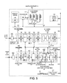
FIG. 5 is a more detailed diagram of the digital baseband integratedcircuit 103 of the mobile communication device ofFIG. 3 . -
FIG. 6 is a more detailed diagram of the demap/de-interleave/decode (DDE) Wireless Communication System Modem Sub-Circuit (WCSMSC) 125 ofFIG. 5 . -
FIG. 7 is a more detailed diagram of thedecoder block 202 of the DDE WCSMSC 125 ofFIG. 6 . -
FIG. 8 is a diagram of a DDE execute task instruction. -
FIG. 9 is a diagram showing how fields of the DDE execute task instruction ofFIG. 8 identify the location of a sub-packet in theLLR buffer 129 ofFIG. 6 . -
FIG. 10 is a diagram that illustrates a group of packets. Each packet of the group includes a plurality of sub-packets. -
FIG. 11 is a diagram that illustrates a first scenario in which a seconddecoder DECODER# 2 finishes decoding its assigned sub-packets of the group ofFIG. 10 before a firstdecoder DECODER# 1 finishes decoding its assigned sub-packets of the group. -
FIG. 12 is a diagram that illustrates a second scenario in which the firstdecoder DECODER# 1 finishes decoding its assigned sub-packets of the group ofFIG. 10 before the seconddecoder DECODER# 2 finishes decoding its assigned sub-packets of the group. -
FIG. 13 is a diagram that illustrates how novel EOP and EOG markers are used in task instructions to generate an end-of-packet interrupt signal to theprocessing circuit 115 ofFIG. 5 without halting either of the two cooperating decoders, without generating two EOP interrupts at the end of the first packet and without generating two EOG interrupts at the end of the group. At the end-of-group, a single EOG interrupt is generated, but the first decoder to finish processing its assigned sub-packets of the group is halted. -
FIG. 14 is a diagram that illustrates how the novel EOP and EOG markers and task instructions are used to generate the desired EOP and EOG interrupts in the second scenario in which the firstdecoder DECODER# 1 finishes first. -
FIG. 15 is a simplified flowchart of a method in accordance with one novel aspect. -
FIG. 3 is a simplified high level block diagram of an example of awireless communication device 100.Wireless communication device 100 includes, among other parts not illustrated, anantenna 101, a Radio Frequency (RF)integrated circuit 102, and a digital baseband integratedcircuit 103. -
FIG. 4 is a more detailed block diagram of theantenna 101 and the RF transceiver integratedcircuit 102 ofFIG. 3 . The RF transceiver integratedcircuit 102 includes a receivechain 104 and a transmitchain 105. Anincoming transmission 106 is received onantenna 101, and passes through aduplexer 107 and amatching network 108 and into the receivechain 104. After being downconverted in frequency in receivechain 104, the received signal passes to an Analog-to-Digital Converter (ADC) 109 in the digital baseband integratedcircuit 103 for further processing. Ifwireless communication device 100 is to make a transmission, then digital information is converted into analog form by a Digital-to-Analog Converter (DAC) 110 in the digital baseband integratedcircuit 103. The resulting analog signal is then upconverted in frequency by transmitchain 105 of the RF transceiver integratedcircuit 102, and the resulting RF signal is amplified bypower amplifier PA 111. The amplified signal passes throughduplexer 107 and toantenna 101 for transmission asoutgoing transmission 112. -
FIG. 5 is a more detailed block diagram of digital baseband integratedcircuit 103 ofFIG. 3 . Digital baseband integratedcircuit 103 includes, among other portions not illustrated,ADC 109, a receivechannel 113, a transmitchannel 114,DAC 110, aprocessing circuit 115, an amount ofmemory 116, an amount of high-speed memory 117, adata mover engine 118, afirst bus 119, asecond bus 120, and awall clock timer 121. Receivechannel 113 in turn includes a set of processing blocks 122-125, referred to here as Wireless Communication System Modem Sub-Circuits (WCSMSCs). The WCSMSCs are organized in a chain to process a stream of incoming data. These WCSMSCs include afront end WCSMSC 122, a Fast Fourier Transform (FFT)WCSMSC 123, ademodulate WCSMSC 124, and a Demap/De-Interleave/Decode (DDE)WCSMSC 125.DDE WCSMSC 125 in turn includes a demapper portion, anLLR buffer 129, and a decoder block as explained below in further detail. Data flow passing through the various WCSMSCs of the receivechannel 113 is buffered by buffers 126-130. The general path of receive channel data is from left to right inFIG. 5 throughcircuits second bus 120. Similarly, transmitchannel 114 includes a corresponding set of WCSMSCs 131-134 and buffers 135-138. The general path of transmit channel data is from right to left inFIG. 5 fromsecond bus 120, to 135, 131, 136, 132, 137, 133, 138, 134, and 110. -
Processing circuit 115 may include multiple processors.Processing circuit 115 executes aprogram 139 of processor-executable instructions stored inmemory 116. High-speed memory 117,first bus 119 andprocessing circuit 115 together form a Tightly Coupled Memory (TCM) system.Processing circuit 115 can read from and write to high-speed memory 117 acrossfirst bus 119. - In this example,
processing circuit 115 controls the various sub-circuits 122-125 and 131-134 of the receive and transmit channels using what are called "task lists". A task list includes one or more task instructions. In the illustration, four task lists TL1, TL2, TL3 and TL4 are shown stored inmemory 117. Task list TL1 contains task instructions for the transmitchannel 114. Task list TL2 contains task instructions forFFT WCSMSC 123. Task list TL3 contains task instructions forDEMOD WCSMSC 124. Task list TL4 contains task instructions forDDE WCSMSC 125. Each task list contains a sequence of task instructions for execution by an associated sub-circuit. The sub-circuit includes a task manager circuit that is coupled tosecond bus 120 as well as an amount of dedicated functional circuitry for performing the data processing operation of the circuit. The task manager reads a task instruction from its associated task list, and interprets an opcode and various fields of the task instruction, and then controls the associated hardware of the dedicated functional circuitry to perform an operation as indicated by the task instruction. By placing appropriate task instructions into the task list for a particular sub-circuit,processing circuit 115 can cause the dedicated functional circuitry of a particular sub-circuit to perform a particular operation specified by the processing circuit.Processing circuit 115 can write task instructions into these task lists, modify these task lists, delete task lists, and otherwise maintain the task lists as desired viafirst bus 119. Each task list is maintained inmemory 117 in a circular buffer. The task manager forDDE WCSMSC 125 inFIG. 5 is identified byreference numeral 140. The associated dedicated functional circuitry controlled bytask manager 140 includes the demapper block and the deocoder block. -
FIG. 6 is a more detailed block diagram ofDDE WCSMSC 125 ofFIG. 4 . The demapper block ofDDE WCSMSC 125 actually includes twodemap circuits decoder block 202 ofDDE WCSMSC 125 includes twoViterbi decoders turbo decoders flow control circuit 207, andmemory interface circuitry 208. In addition to the demap and decoder blocks,DDE WCSMSC 125 includes apush engine 209, abus interface 210 for interfacing tosecond bus 120, a set of configuration, status and pointer registers 211, and amemory interface 212. Thetask manager 140 ofFIG. 5 is distributed into task manager blocks 213 and 214 and registers 211. The overall task manager functionality receives task instructions. Some of these task instructions include fields for controllingdemap circuit 200 and those fields are interpreted and used bytask manager portion 213, whereas other fields are for controllingdemap circuit 201 and those fields are interpreted and used bytask manager portion 214.Processing circuit 115 ofFIG. 5 generally writes a task instruction onto task list TL4 forDDE WCSMSC 125, and then performs a single write acrosssecond bus 120 andAHB bus interface 210 intoregister block 211 to update a WR_PTR pointer value stored inblock 211. Thetask manager portions block 211 now points to a location in the TL4 circular buffer in memory 117 (seeFIG. 5 ) after the last task instruction executed. The task manager portions therefore read the next task instruction of TL4 acrosssecond bus 120, and then interpret and execute the task instruction. The task manager portions ofDDE WCSMSC 125 maintain an EXEC_PTR pointer in another register inregister block 211. The value of the EXEC_PTR pointer indicates the last task instruction in task list TL4 that has been executed. -
Demap portion 200 ofFIG. 6 is a relatively low throughput demap circuit used for control packets, whereasdemap portion 201 is a relatively high throughput demap circuit used for data packets.Demap portion 200 includes the following functional blocks: anunpaint block 215, a Log-Likelihood Ratio (LLR)generator block 216, adescramber block 217, and ade-interleaver block 218.Demap portion 200 interfaces toLLR buffer 129 viaconductors 219 that provide two parallel read/write channels into and out of the LLR buffer. Higherthroughput demap portion 201 includes the following functional blocks: anunpaint block 220, anLLR generator block 221, adescramber block 222, and ade-interleaver block 223.Demap portion 201 interfaces toLLR buffer 129 via conductors 244 that provide six parallel read/write channels into and out ofLLR buffer 129.LLR buffer 129 is a multi-banked memory that can simultaneously receive six LLR values fromdemap 201 and two LLR values fromdemap 200.Decoder block 202 reads LLR values out ofLLR buffer 129 in de-interleaved order viaconductors 233, performs decoding as specified by task instructions, and writes the resulting decoded data intodecode output buffer 130 viaconductors 234. - Once a demap/de-interleave/decode operation has been initiated, processing always proceeds through each successive step from the unpaint step, to LLR generation, to descrambling, to de-interleaving, to decoding. A separate task instruction for each of these steps is therefore not necessary to control the demap, de-interleave and decode aspects of processing. Rather, a single task instruction is used to control the entire sequence of processing through these steps. Once a
demap block Decoder block 202 then processes the received sub-packet as soon as possible. One of the demap blocks 200 and 201 forwards a sub-packet to decoder block 202 by first writing the sub-packet of LLR values into a portion ofLLR buffer 129, and then informingdecoder block 202 viaconductors LLR buffer 129 and where thedecoder block 202 should write the result of decoding intodecode output buffer 130. The forwarding also involves the demap block forwarding status information associated with the sub-packet directly to thedecoder block 202 viaconductors -
FIG. 7 is a more detailed block diagram of a part ofdecoder block 202 ofFIG. 6 .Viterbi decoders FIG. 6 are not pictured inFIG. 7 . The functionality ofmemory interface circuitry 208 ofFIG. 6 is shown in more detail inFIG. 7 inmemory interface circuits turbo decoders - Under the control of
processing circuit 115 through the issuing of a DDE execute task instruction, an individual one of the sub-packets is processed by a selected one ofdecoders - Configurable
flow control logic 207 includes one sequential data storage bit for storing CRC (cyclic redundancy check) pass/fail information for each sub-packet of a group of packets being decoded byDDE WCSMSC 125. In the illustrated example ofFIG. 7 , a group can include at most two packets, and a packet can include at most thirty-two sub-packets. Accordingly, there are sixty-fourCRC storage bits 227. If the one ofdecoders bits 227 is reset to have a logic state "0", whereas if the determination was that there was a CRC pass then the corresponding bit is set to have a logic state "1". - In addition, configurable
flow control logic 207 includes fourbits 228 for storing configuration information: a DEC_INT_ENABLE1 bit, a DEC_INT_ENABLE2 bit, a DEC_RESOURCE_USE1 bit, and a DEC_RESOURCE_USE2 bit. If the DEC_RESOURCE_USE1/2 bits are set to have the two-bit value "00", then thedecoder block 202 is set to operate in a single decoder mode. Only one of the two decoders processes sub-packets of a packet. If the DEC_RESOURCE_USE1/2 bits are set to have the two-bit value "01", then thedecoder block 202 is set to operate in a dual decoder group mode in which sub-packets of the group of sub-packets being processed are processed by a combination of the twodecoders decoder block 202 is set to operate in a dual decoder packet mode in which sub-packets of a packet being processed are processed by a combination of the twodecoders conductor 231.Signal conductor 231 extends to an interrupt controller (not shown), which in turn asserts an interrupt signal toprocessing circuit 115 ofFIG. 5 . If the DEC_INT_ENABLE1/2 bits are set to have the two-bit value "01", then interrupt generator 229 is configured into IMMEDIATE interrupt generation mode in which an interrupt is asserted immediately upon decoding of the current sub-packet. If the DEC_INT_ENABLE1/2 bits are set to have the two-bit value "10", then interrupt generator 229 is configured into PACKET interrupt generation mode in which an interrupt is asserted upon completion of decoding of the current packet being processed. If the DEC_INT_ENABLE1/2 bits are set to have the two-bit value "11", then interrupt generator 229 is configured into a GROUP interrupt generation mode in which an interrupt is asserted upon completion of decoding of the current group being processed. - In addition, configurable
flow control logic 207 includes six "done"bits 230 of information: a bit that stores an indication thatDECODER# 1 has completed decoding all its assigned sub-packets ofPACKET# 1, a bit that stores an indication thatDECODER# 2 has completed decoding all its assigned sub-packets ofPACKET# 1, a bit that stores an indication thatDECODER# 1 has completed decoding all its assigned sub-packets ofPACKET# 2, a bit that stores an indication thatDECODER# 2 has completed decoding all its assigned sub-packets ofPACKET# 2, a bit that stores an indication thatDECODER# 1 has completed decoding all its assigned sub-packets of a group, and a bit that stores an indication thatDECODER# 2 has completed decoding all its assigned sub-packets of a group. How these bits are set and used is described in further detail below. -
FIG. 8 is a simplified diagram of the DDE execute task instruction that causesDDE WCSMSC 125 to process an individual sub-packet. The first sixty-four bits of the task instruction is a common header that includes an opcode OP. The task manager that reads the task instruction interprets the opcode to determine what kind of task instruction the task instruction is. The common header also includes a length field that indicates the number of words in the task instruction. The task manager reading the task instruction frommemory 117 uses this length field to determine how many words to read. Some of the other fields of the DDE execute task instruction pertain particularly todecoder block 202. These fields include a three-bit DEC_LLR_SEG field that indicates which one of eight segments of the LLR buffer holds the LLR values to be decoded.FIG. 9 illustrates eight segments of the LLR buffer. The fields of the DDE execute task instruction that pertain to the decoder block also include an eleven-bit DEC_LLR_SEG_OFFSET field that indicates at offset between the beginning of the indicated segment to the location where the sub-packet data begins.FIG. 9 illustrates this offset. The DDE execute task instruction also includes a sixteen-bit DEC_SUBPKT_SIZE field that indicates the length of the sub-packet as stored in the LLR buffer.FIG. 9 illustrates this size. Together, the DEC_LLR_SEG, DEC_LLR_SEG_OFFSET and DEC_SUBPKT_SIZE fields identify the source sub-packet data to be processed bydecoder block 202. The DDE execute task instruction also includes information on where to store results of the decode operation. The sixteen-bit DEC_OB_DEST_ADDR field indicates the starting address in thedecode output buffer 130 where the decode outputs are to be written. In addition, the DDE execute task instruction includes a six-bit DEC_SUBPKT_INDEX field that indicates a number (sub-packet index) that identifies the sub-packet to be processed from the other sub-packets of the stream. As indicated above, there may be two packets in the group of packets being processed, so the DDE execute task instruction includes a one-bit DEC_PKT_NUMBER field that identifies whether the packet to which the sub-packet belongs is the first or the second packet of the group. The DDE execute task instruction also includes other fields of bits as indicated above (DEC_RESOURCE_USE and DEC_INT_ENABLE) that specify the configuration that the decoder block should have in processing the identified sub-packet. If the sub-packet to be processed by a particular decoder is the last sub-packet to be assigned to the decoder for the current packet, then the one-bit EOP field (end-of-packet) is set to mark the associated sub-packet. If the sub-packet to be processed by a particular decoder is the last sub-packet to be assigned to the decoder for the current group, then the one-bit EOG field (end-of-group) is set to mark the associated sub-packet. The value in a three-bit DEC_SEL field determines which of the two decoders should process the sub-packet or if neither of the two decoders should process the sub-packet.Processing circuit 115 can set the value in this field to specify which of the decoders should perform decoding on the sub-packet, or whether in a test mode neither of the decoders should be used. - The DEC_GEN_TX_ACK field indicates whether the
DDE WCSMSC 125 should assert a hardware event trigger signal onto a point-to-point conductor 237 to transmit channel 114 (seeFIG. 5 ).Processing circuit 115 can, via a task instruction provided to the transmit channel, set up a transmission in the transmitchannel 114 where the transmission will either be an acknowledgement (ACK) transmission or will be a negative acknowledgement (NACK) transmission depending on a result of processing bydecoder block 202. Theprocessing circuit 115 also causes theflow control logic 207 to assert the hardware event trigger signal ontoconductor 237 such that this trigger signal supplies to the transmit channel 114 (seeFIG. 5 ) the result of the decoding operation, thereby determining whether the transmission is an ACK or NACK. The use of a hardware event trigger signal in this fashion reduces latency in returning an ACK/NACK to a transmitting device. -
FIG. 10 is a diagram of agroup 300 of sub-packets to be processed byDDE WCSMSC 125 in an operational example described below.Group 300 includes two packets:PACKET# 1 andPACKET# 2. Individual sub-packets in the diagram are identified by the notation of the form of a first numeral, followed by a colon, followed by a second numeral. The second numeral indicates the packet number. The first numeral indicates the number of the sub-packet within the packet. Each sub-packet includes a CRC value as illustrated. -
FIG. 11 is a diagram that illustrates a first scenario of decoding of the sub-packets ofFIG. 10 bydecoders DECODER# 2. AfterDECODER# 1 has decoded all sub-packets assigned to it for the first packet, then it is to decode sub-packets 6:2, 7:2 and 8:2 of the second packet. AfterDECODER# 2 has decoded all sub-packets assigned to it for the first packet, then it is to decode sub-packets 9:2 and 10:2 of the second packet. In the diagram ofFIG. 11 , time extends from left to right. The duration of the processing of each sub-packet in the diagram ofFIG. 11 is indicated by the length of the block representing the sub-packet. Due to the amounts of time consumed in the decoding of the various sub-packets,DECODER# 2 finishes decoding sub-packets of the second packet at the time indicated byarrow 301 beforeDECODER# 1 finishes decoding sub-packets of the second packet. -
FIG. 12 is a diagram that illustrates a second scenario of decoding of the sub-packets ofFIG. 10 bydecoders FIG. 12 , due to the amounts of time consumed in the decoding of the various sub-packets,DECODER# 1 finishes decoding sub-packets of the second packet at the time indicated byarrow 302 beforeDECODER# 2 finishes decoding sub-packets of the second packet. Regardless of which scenario occurs, it is desired that only one interrupt indicating that processing has been completed be sent toprocessing circuit 115. Depending on how theDDE WCSMSC 125 is configured by processingcircuit 115, it may be desired that an additional interrupt be sent toprocessing circuit 115 after all sub-packets of the first packet have been processed.Novel DDE WCSMSC 125 is configurable to perform these functions as set forth below. -
FIG. 13 is a diagram that illustrates how thenovel DDE WCSMSC 125 operates to generate one and only one interrupt upon completion of decoding of the last sub-packet of the first packet, and how theDDE WCSMSC 125 also operates to generate one and only one interrupt upon completion of decoding of the last sub-packet of the group. In one novel aspect,processing circuit 115 marks the last sub-packet of a packet being assigned for decoding to a decoder. For example, the last sub-packet of the first packet to be assigned for decoding toDECODER# 1 is sub-packet 2:1. This sub-packet 2:1 is therefore marked as being the last sub-packet of the first packet by setting the EOP bit in the DDE execute task instruction for sub-packet 2:1. This marking is schematically indicated inFIG. 13 by thecross-hatched mark 303. Similarly, the last sub-packet of the first packet to be assigned for decoding toDECODER# 2 is sub-packet 5:1. This sub-packet is therefore marked as being the last sub-packet of the first packet by setting the EOP bit in the DDE execute task instruction for sub-packet 5:1. This marking is schematically indicated inFIG. 13 by thecross-hatched mark 304. - When one of the decoders completes decoding a sub-packet marked with an EOP marker being set, then that decoder generates a packet done indication by setting which ever one of its
PACKET# 1 DONE andPACKET# 2 DONE bits is appropriate as determined by the DEC_PKT_NUMBER of the sub-packet just decoded. ThePACKET# 1 DONE andPACKET# 2 DONE bits are located inflow control logic 207. When both of thePACKET# 1 DONE andPACKET# 2 DONE bits inflow control logic 207 are detected to have been set, then interrupt generator 229 asserts an interrupt signal on interruptconductor 231. This is indicated inFIG. 13 byarrow 305. As a decoder completes decoding each sub-packet, the decoder causes the corresponding bit in the CRC pass/failbits 227 to be set or reset depending on whether the CRC check performed on the sub-packet passed or failed. The packet number of the pass/fail bit is given by the DEC_PKT_NUMBER value of the sub-packet being decoded. The sub-packet number of the pass/fail bit is given by the DEC_SUBPKT_INDEX value of the sub-packet being decoded. These DEC_PKT_NUMBER (PKT#) and DEC_SUBPKT_INDEX (SUBPKT#) values are supplied byconductors 232 from the decoder doing the decoding to flowcontrol logic 207 ofFIG. 7 . - When the interrupt signal on
conductor 231 is asserted, the interrupt signal is supplied to an input lead of the interrupt controller (not shown). The interrupt controller in turn asserts an interrupt signal that is supplied toprocessing circuit 115. This interrupt indicates that all sub-packets of the first packet have been decoded. As a result of the asserting of the interrupt signal,processing circuit 115 is interrupted and jumps to an interrupt service routine. In executing the interrupt service routine,processing circuit 115 performs various reads to determine what caused the interrupt.Processing circuit 115 reads theCRC bits 227 and other status information collected byflow control logic 207 viaAHB bus interface 210 andsecond bus 120. The status information indicates what condition caused interrupt generator 229 to assert the interrupt signal. The reading of the CRC value and the status information by processingcircuit 115 causes interrupt generator 229 to be reset such that the interrupt signal onconductor 231 is no longer asserted. The clearing of the interrupt is indicated inFIG. 7 by the signal labeled CLEAR. The reading back of the CRC bit values and status information is indicated inFIG. 7 by the signals labeled STATUS. Once the interrupt signal onconductor 231 has been returned to its unasserted state, the interrupt signal can again be asserted to indicate another condition. - Returning to
FIG. 13 , theDDE WCSMSC 125 is configured to assert an interrupt at the end of decoding of the group. One and only one interrupt is to be generated at thistime 306. In one novel aspect,processing circuit 115 marks the last sub-packet of the group being assigned for decoding to each decoder. For example, the last sub-packet of the group to be assigned for decoding toDECODER# 1 is sub-packet 8:2. Sub-packet 8:2 is therefore marked as being the last sub-packet of the group by setting the EOG bit in the DDE execute task instruction for sub-packet 8:2. This marking is indicated inFIG. 13 by the solidblack mark 307. The last sub-packet of the group to be assigned for decoding toDECODER# 2 is sub-packet 10:2. Sub-packet 10:2 is therefore marked as being the last sub-packet of the group by setting the EOG bit in the DDE execute task instruction for sub-packet 10:2. This marking is indicated inFIG. 13 by the solidblack mark 308. When one of the decoders completes decoding a sub-packet marked with an EOG bit being set, then that decoder generates a group done indication by setting its GROUP DONE bit. When both of the GROUP DONE bits are set, then interrupt generator 229 asserts the interrupt signal on interruptconductor 231. This is indicated inFIG. 13 byarrow 306. As in the case of the interrupt generated by the EOP condition attime 305, theprocessing circuit 115 is interrupted. Theprocessing circuit 115 responds by executing an interrupt service routine, execution of which causesprocessing circuit 115 to read the CRC values and other status information fromflow control logic 207. The status information read indicates that the interrupt signal was asserted due to an end-of-group (EOG) condition. The reading of the CRC values and status information causes the interrupt signal to return to its unasserted state so that it can be asserted again to signal the occurrence of another condition. Note that in the example ofFIG. 13 , the EOP interrupt signal asserting occurs only once, even though multiple decoders are used in processing sub-packets of the first packet. Note also that in the example ofFIG. 13 , the EOG interrupt signal asserting occurs only once, even though multiple decoders are used in the decoding the last packet of the group. None of the multiple decoders is halted after completing the decoding of sub-packets for the first packet, but rather all decoders continue on decoding sub-packets as instructed by task instructions. In the embodiment ofFIG. 7 when a decoder completes decoding the last sub-packet assigned to it for the group as indicated by the EOG mark, then flowcontrol logic 207 asserts a halt signal that is sent back to the decoder to halt operation of that decoder. InFIG. 7 , these halt signals are communicated acrossconductors FIG. 13 , thesecond DECODER# 2 that completes processing first is halted attime 309. The halt condition is removed upon clearing of the interrupt by processingcircuit 115. -
FIG. 14 is a diagram that illustrates how thenovel DDE WCSMSC 125 operates in the second scenario in whichDECODER# 1 finishes decoding sub-packets of the group beforeDECODER# 2. WhenDECODER# 1 completes decoding sub-packet 2:1 it causes thePACKET# 1 DONE bit forDECODER# 1 to be set in theflow control logic 207. This is accomplished by sending appropriate status signals acrossconductors 232. Appropriate status signals include a DONE signal, a packet index PKT#, and an end-of-packet (EOP) signal. Even thoughDECODER# 1 has completed decoding all sub-packets assigned to it for the first packet, and even though more sub-packets of the first packet remain to be decoded by the otherdecoder DECODER# 2,DECODER# 1 nevertheless continues decoding sub-packets without delay.DECODER# 1 immediately begins decoding sub-packet 6:2. ThePACKET# 2 DONE bit forDECODER# 2 is not set at this point becauseDECODER# 2 is still decoding sub-packets of the first packet. WhenDECODER# 2 finishes decoding the last sub-packet assigned to it for the first packet (sub-packet 5:1), thenDECODER# 2 generates a packet done indication by setting thePACKET# 1 DONE bit forDECODER# 2 inflow control logic 207. Because both PACKET DONE bits are set, the interrupt controller 229 asserts the interrupt signal onconductor 231 attime 310. Similarly, the interrupt signal is only asserted once at time 311 in response to both decoders having completed decoding all their assigned sub-packets for the group. The firstdecoder DECODER# 1 completed decoding its last assigned sub-packet of the group at time 312.Flow control logic 207 is aware of this condition due to the first decoder supplying the flow control logic 207 a group done indication.Flow control logic 207 responds by asserting a halt signal that is supplied back toDECODER# 1 onconductor 235, thereby haltingDECODER# 1. Onceprocessing circuit 115 has read the CRC information and other status information in response to the EOG interrupt, then the halt condition is removed. -
FIG. 15 is a flowchart of amethod 400 in which a plurality of decoders work together (step 401) to decode various sub-packets of a packet. Some of the sub-packets decoded by a particular decoder are from a particular packet (designated here as "PKT") of the plurality of packets. The particular packet PKT can be any packet in a group of packets. For example, as shown inFIG. 13 , sub-packets 1:1 and 2:1 of a first packet (the "PKT" packet) are decoded by a first decoder, whereas sub-packets 3:1, 4:1 and 5:1 of the first packet are decoded by a second decoder. A packet done indication is received (step 402) from a decoder when that decoder has decoded the last sub-packet of the packet PKT that the decoder was assigned to decode. For example, as shown inFIG. 13 , the first decoder was assigned to decode sub-packets 1:1 and 2:1 of the first packet (the "PKT" packet), and when the first decoder completes decoding sub-packet 2:1 (which is the last sub-packet of the first packet that the first decoder is to decode), then the first decoder generates a first packet done indication. This first packet done indication is received byflow control logic 207 ofFIG. 7 and results in thePACKET# 1 DONE bit for the first decoder being set. Similarly, the second decoder was assigned to decode sub-packets 3:1, 4:1 and 5:1 of the first packet. When the second decoder completed decoding sub-packet 5:1 (which is the last sub-packet of the first packet that the second decoder is to decode), then the second decoder generates a second packet done indication. This second packet done indication is received by theflow control logic 207 ofFIG. 7 and results in thePACKET# 1 DONE bit for the second decoder being set. If a packet done indication has been received from all the decoders that are decoding sub-packets of the particular packet PKT (step 403), then an action is initiated (step 404). In one example, the action initiated is the assertion of an interrupt signal ontoconductor 231 byflow control logic 207. Theprocessing circuit 115 may then respond by reading information fromflow control logic 207, thereby resetting the interrupt signal. - The techniques described herein may be implemented by various means. In one or more exemplary embodiments, the functions described may be implemented in hardware, software, firmware, or any combination thereof. If implemented in software, the functions may be stored on or transmitted over as one or more instructions or code on a computer-readable medium. Computer-readable media includes both computer storage media and communication media including any medium that facilitates transfer of a computer program from one place to another. A storage media may be any available media that can be accessed by a computer. By way of example, and not limitation, such computer-readable media can comprise RAM, ROM, EEPROM, CD-ROM or other optical disk storage, magnetic disk storage or other magnetic storage devices, or any other medium that can be used to carry or store desired program code in the form of instructions or data structures and that can be accessed by a computer. Also, any connection is properly termed a computer-readable medium. For example, if the software is transmitted from a website, server, or other remote source using a coaxial cable, fiber optic cable, twisted pair, digital subscriber line (DSL), or wireless technologies such as infrared, radio, and microwave, then the coaxial cable, fiber optic cable, twisted pair, DSL, or wireless technologies such as infrared, radio, and microwave are included in the defmition of medium. Disk and disc, as used herein, includes compact disc (CD), laser disc, optical disc, digital versatile disc (DVD), floppy disk and blu-ray disc where disks usually reproduce data magnetically, while discs reproduce data optically with lasers. Combinations of the above should also be included within the scope of computer-readable media.
- Although certain specific embodiments are described above for instructional purposes, the teachings of this patent document have general applicability and are not limited to the specific embodiments described above. Accordingly, various modifications, adaptations, and combinations of the various features of the described specific embodiments can be practiced without departing from the scope of the claims that are set forth below.
-
- 1. A circuit comprising:
- a plurality of decoders, wherein each decoder can be assigned tasks of decoding a sequence of one or more sub-packets of a group of packets, wherein said each decoder generates a packet done indication if the decoder has completed all the assigned tasks of decoding all the sub-packets of a packet; and
- a control circuit that receives the packet done indication from each of the plurality of decoders and based at least in part on the packet done indications asserts an interrupt signal, wherein the interrupt signal is not asserted during a time that any decoder is decoding a sub-packet of the packet but rather is asserted only after a packet done indication has been received from every decoder that decoded any sub-packet of the packet.
- 2. The circuit of 1, wherein the packet done indication includes a done signal and an end-of-packet signal, wherein the done signal is present on a first conductor extending from a decoder and into the control circuit, and wherein the end-of-packet signal is present on a second conductor extending from the decoder and into the control circuit.
- 3. The circuit of 1, wherein said each decoder supplies a group done indication if the decoder has completed all the assigned tasks of decoding all sub-packets of the group of packets, wherein the control circuit receives a group done indication from each of the plurality of decoders.
- 4. The circuit of 1, wherein the control circuit generates a plurality of halt signals, wherein one of the plurality of halt signals is supplied to a corresponding respective one of the plurality of decoders.
- 5. The circuit of 4, wherein the control circuit uses the halt signals to halt individual ones of the decoders as they complete decoding all their assigned tasks of decoding sub-packets of the group.
- 6. The circuit of 1, wherein the control circuit is configurable to assert the interrupt signal in response to packet done indications having been received from every decoder that decoded a sub-packet of the packet, and wherein the control circuit is also configurable such that the control circuit does not assert the interrupt signal in response to receiving a packet done indication.
- 7. The circuit of 1, wherein the interrupt signal is an end-of-packet (EOP) interrupt signal, and wherein the control circuit is also configurable such that the control circuit does not assert the EOP interrupt signal.
- 8. The circuit of 1, wherein the circuit is operable such that one of the decoders decodes a sequence of sub-packets of a first packet and supplies a packet done indication to the control circuit and then begins decoding a sequence of sub-packets of a second packet without being halted, wherein the first and second packets are packets of the group, and wherein the control circuit does not assert the interrupt signal at the time the control circuit receives the packet done indication from said one decoder but rather asserts the interrupt signal once after packet done indications have been received from every decoder that decoded any sub-packet of the packet.
- 9. The circuit of 1, wherein the packet done indication supplied by a decoder is received by the control circuit along with a sub-packet index, wherein the sub-packet index identifies the last sub-packet of the packet that the decoder decoded.
- 10. The circuit of 1, wherein the packet done indication supplied by a decoder is received by the control circuit along with a packet index, wherein the packet index identifies the packet to which the packet done indication pertains.
- 11. The circuit of 1, further comprising:
- a processor that can assign one of the plurality of decoders a task of decoding a sub-packet by generating a task instruction, wherein the task instruction includes information indicating where the sub-packet is located in a buffer.
- 12. The circuit of 1, further comprising:
- a processor that can assign one of the plurality of decoders a task of decoding a sub-packet by generating a task instruction, wherein the task instruction includes an indication of whether the sub-packet is the last sub-packet of a sequence of sub-packets of a packet, wherein the sequence of sub-packets is to be decoded by said one decoder.
- 13. The circuit of 1, further comprising:
- a processor that can assign one of the plurality of decoders a task of decoding a sub-packet by generating a task instruction, wherein the task instruction includes an indication of whether the sub-packet is the last sub-packet of a sequence of sub-packets of a group of packets, wherein the sequence of sub-packets is to be decoded by said one decoder.
- 14. The circuit of 1, wherein one of the decoders decodes a sub-packet in response to a task instruction, wherein the task instruction identifies the sub-packet and includes a field containing an end-of-packet bit, and wherein the decoder asserts its packet done indication upon completion of decoding the sub-packet if the end-of-packet bit has a predetermined binary value.
- 15. A circuit comprising:
- a first turbo decoder adapted to decode a sequence of first sub-packets without halting until a last one of the first sub-packets has been decoded, wherein some of first sub-packets are of a first packet and others of the first sub-packets are of a second packet;
- a second turbo decoder adapted to decode a sequence of second sub-packets without halting until a last one of the second sub-packets has been decoded, wherein some of the second sub-packets are of the first packet and others of the second sub-packets are of the second packet;
- a processing circuit; and
- a control circuit that is configurable to alert the processing circuit when all sub-packets of the first packet have been decoded.
- 16. The circuit of 15, wherein the first sub-packets are sub-packets of a group of packets, wherein the second sub-packets are sub-packets of the same group of packets, wherein the first turbo decoder halts decoding sub-packets if it completes decoding of all the first sub-packets of the group before the second turbo decoder completes decoding of all the second sub-packets of the group, and wherein the second turbo decoder halts decoding sub-packets if it completes decoding of all the second sub-packets of the group before the first turbo decoder completes decoding of all the first sub-packets of the group.
- 17. A method comprising:
- using a plurality of decoders to decode a plurality of sub-packets of a group of packets, wherein some of the sub-packets are of a first packet, wherein others of the sub-packets are of a second packet, wherein the group of packets includes the first and second packets;
- maintaining an interrupt signal in an unasserted state throughout a time when sub-packets of the first packet are being decoded by the plurality of decoders; and
- asserting the interrupt signal when all the sub-packets of the first packet have been decoded.
- 18. The method of 17, wherein a first decoder of the plurality of decoders decodes sub-packets of the first packet and then decodes sub-packets of the second packet without halting, and wherein a second decoder of the plurality of decoders decodes sub-packets of the first packet and then decodes sub-packets of the second packet without halting.
- 19. The method of 17, wherein some of the sub-packets of the first packet are decoded by a first decoder of the plurality of decoders, and wherein others of the sub-packets of the first packet are decoded by a second decoder of the plurality of decoders.
- 20. The method of 17, further comprising:
- receiving a packet done indication from each of the plurality of decoders and using the packet done indications received from the plurality of decoders to determine when to assert the interrupt signal.
- 21. The method of 17, further comprising:
- halting any decoder of the plurality of decoders that completes decoding sub-packets of the group before another decoder of the plurality of decoders has completed decoding sub-packets of the group.
- 22. A method comprising:
- receiving a first task instruction, wherein the first task instruction includes identification information that identifies a first sub-packet, and wherein the first task instruction further includes a marker;
- decoding the first sub-packet indicated by the identification information in the first task instruction and upon completion of the decoding setting a first bit in a control circuit if the marker of the first task instruction was set;
- receiving a second task instruction, wherein the second task instruction includes identification information that identifies a second sub-packet, and wherein the second task instruction further includes a marker, wherein the first and second sub-packets are sub-packets of a packet;
- decoding the second sub-packet indicated by the identification information in the second task instruction and upon completion of the decoding setting a second bit in the control circuit if the marker of the second task instruction was set; and
- using the first and second markers in the control circuit to initiate an action.
- 23. The method of 22, wherein the action initiated is an assertion of an interrupt signal output from the control circuit.
- 24. The method of 22, wherein the action initiated is a sending of an acknowledgement (ACK) transmission.
- 25. The method of 22, wherein the marker of the first task instruction is an end-of-packet (EOP) marker bit.
- 26. The method of 22, wherein the marker of the first task instruction is an end-of-group (EOG) marker bit, and wherein the packet is one packet of a plurality of packets of a group.
- 27. An apparatus comprising:
- a first turbo decoder adapted to decode a sequence of first sub-packets, wherein some of first sub-packets are of a first packet and others of the first sub-packets are of a second packet;
- a second turbo decoder adapted to decode a sequence of second sub-packets, wherein some of the second sub-packets are of the first packet and others of the second sub-packets are of the second packet; and
- means for receiving a packet done indication from the first turbo decoder and for receiving a packet done indication from the second turbo decoder, wherein the means is also for maintaining a packet done interrupt signal in an unasserted state throughout a time when sub-packets of the first packet are being decoded by the first and second turbo decoders, and for asserting the packet done interrupt signal when all the sub-packets of the first packet have been decoded.
- 28. The apparatus of 27, wherein the apparatus is configurable into a selectable one of a plurality of modes, and wherein in one mode the means is configured not to assert a packet done interrupt signal.
- 29. The apparatus of 27, wherein the apparatus is configurable into a selectable one of a plurality of modes, wherein in one mode the means does not assert a group done interrupt signal, and wherein in another mode the means does assert the group done interrupt signal.
- 30. The apparatus of 27, wherein all sub-packets of a third packet can be decoded by the first turbo decoder such that no sub-packets of the third packet are decoded by the second turbo decoder.
- 31. The apparatus of 27, wherein the means is also for storing a Cyclic Redundancy Check (CRC) pass/fail bit for each sub-packet of the first packet, and for each sub-packet of the second packet.
- 32. A computer program product, comprising:
- computer-readable medium comprising:
- code for causing a computer to control a first decoder such that the first decoder decodes a sequence of first sub-packets, wherein some of first sub-packets are of a first packet and others of the first sub-packets are of a second packet, and for controlling the first decoder such that the first decoder generates a first packet done indication upon the first decoder completing decoding all the first sub-packets of the first packet;
- code for causing the computer to control a second decoder such that the second decoder decodes a sequence of second sub packets, wherein some of second sub-packets are of a first packet and others of the second sub-packets are of a second packet, and for controlling the second decoder such that the second decoder generates a second packet done indication upon the second decoder completing decoding all the second sub-packets of the first packet; and
- code for causing the computer to control a control circuit such that the control circuit uses the first and second packet done indications to generate a packet done indication, wherein the packet done indication is not generated during a time that either the first or the second decoder is decoding a sub-packet of the packet but rather is generated only after both the first packet done indication has been received from the first decoder and the second packet done indication has been received from the second decoder.
- computer-readable medium comprising:
- 33. The computer program product of 32, wherein the first decoder decodes the first sub-packets of the first packet and the first sub-packets of the second packet without halting, and wherein the second decoder decodes the second sub-packets of the first packet and the second sub-packets of the second packet without halting.
Claims (7)
- A method for efficient sub-packet decoding comprising:receiving a first task instruction, wherein the first task instruction includes identification information that identifies a first sub-packet, and wherein the first task instruction further includes a marker;decoding the first sub-packet indicated by the identification information in the first task instruction and upon completion of the decoding setting a first bit in a control circuit if the marker of the first task instruction was set;receiving a second task instruction, wherein the second task instruction includes identification information that identifies a second sub-packet, and wherein the second task instruction further includes a marker, wherein the first and second sub-packets are sub-packets of a packet;decoding the second sub-packet indicated by the identification information in the second task instruction and upon completion of the decoding setting a second bit in the control circuit if the marker of the second task instruction was set; andusing the first and second bits set in the control circuit to initiate an action,wherein the marker of the first task instruction is an end-of-packet, EOP, marker bit or an end-of-group, EOG, marker bit, and wherein in the latter case the packet is one packet of a plurality of packets of a group.
- The method of Claim 1, wherein the action initiated is an assertion of an interrupt signal output from the control circuit.
- The method of Claim 1, wherein the action initiated is a sending of an acknowledgement, ACK, transmission.
- A circuit for efficient sub-packet decoding comprising:means for receiving a first task instruction, wherein the first task instruction includes identification information that identifies a first sub-packet, and wherein the first task instruction further includes a marker;means for decoding the first sub-packet indicated by the identification information in the first task instruction and upon completion of the decoding setting a first bit in a control circuit if the marker of the first task instruction was set;means for receiving a second task instruction, wherein the second task instruction includes identification information that identifies a second sub-packet, and wherein the second task instruction further includes a marker, wherein the first and second sub-packets are sub-packets of a packet;means for decoding the second sub-packet indicated by the identification information in the second task instruction and upon completion of the decoding setting a second bit in the control circuit if the marker of the second task instruction was set; andmeans for using the first and second bits set in the control circuit to initiate an action,wherein the marker of the first task instruction is an end-of-packet, EOP, marker bit or an end-of-group, EOG, marker bit, and wherein in the latter case the packet is one packet of a plurality of packets of a group.
- The circuit of Claim 4, wherein the action initiated is an assertion of an interrupt signal output from the control circuit.
- The circuit of Claim 5, wherein the action initiated is a sending of an acknowledgement, ACK, transmission.
- A computer program product, comprising:computer-readable medium comprising:code for causing a computer to carry out the steps of any of claims 1 to 3.
Applications Claiming Priority (3)
| Application Number | Priority Date | Filing Date | Title |
|---|---|---|---|
| US4155808P | 2008-04-01 | 2008-04-01 | |
| US12/400,124 US8665996B2 (en) | 2008-04-01 | 2009-03-09 | Efficient parallel sub-packet decoding using multiple decoders |
| EP09727975A EP2281358B1 (en) | 2008-04-01 | 2009-03-10 | Efficient parallel sub-packet decoding using multiple decoders, controller and task instructions |
Related Parent Applications (2)
| Application Number | Title | Priority Date | Filing Date |
|---|---|---|---|
| EP09727975A Division EP2281358B1 (en) | 2008-04-01 | 2009-03-10 | Efficient parallel sub-packet decoding using multiple decoders, controller and task instructions |
| EP09727975A Division-Into EP2281358B1 (en) | 2008-04-01 | 2009-03-10 | Efficient parallel sub-packet decoding using multiple decoders, controller and task instructions |
Publications (2)
| Publication Number | Publication Date |
|---|---|
| EP2512056A1 true EP2512056A1 (en) | 2012-10-17 |
| EP2512056B1 EP2512056B1 (en) | 2014-08-20 |
Family
ID=41117186
Family Applications (2)
| Application Number | Title | Priority Date | Filing Date |
|---|---|---|---|
| EP09727975A Not-in-force EP2281358B1 (en) | 2008-04-01 | 2009-03-10 | Efficient parallel sub-packet decoding using multiple decoders, controller and task instructions |
| EP12005069.5A Not-in-force EP2512056B1 (en) | 2008-04-01 | 2009-03-10 | Efficient parallel sub-packet decoding using multiple decoders, controller and task instructions |
Family Applications Before (1)
| Application Number | Title | Priority Date | Filing Date |
|---|---|---|---|
| EP09727975A Not-in-force EP2281358B1 (en) | 2008-04-01 | 2009-03-10 | Efficient parallel sub-packet decoding using multiple decoders, controller and task instructions |
Country Status (7)
| Country | Link |
|---|---|
| US (1) | US8665996B2 (en) |
| EP (2) | EP2281358B1 (en) |
| JP (1) | JP5474928B2 (en) |
| KR (1) | KR101141818B1 (en) |
| CN (1) | CN101981852B (en) |
| TW (1) | TW200947932A (en) |
| WO (1) | WO2009123838A2 (en) |
Families Citing this family (8)
| Publication number | Priority date | Publication date | Assignee | Title |
|---|---|---|---|---|
| US9678754B2 (en) * | 2010-03-03 | 2017-06-13 | Qualcomm Incorporated | System and method of processing hierarchical very long instruction packets |
| US20110280133A1 (en) * | 2010-05-11 | 2011-11-17 | Qualcomm Incorporated | Scalable scheduler architecture for channel decoding |
| US20110299442A1 (en) * | 2010-06-04 | 2011-12-08 | Sairamesh Nammi | Methods and apparatus for controlling location for starting decoding of sub-packets of a communication packet |
| US9329872B2 (en) * | 2012-04-27 | 2016-05-03 | Esencia Technologies Inc. | Method and apparatus for the definition and generation of configurable, high performance low-power embedded microprocessor cores |
| CN104427530B (en) * | 2013-08-29 | 2019-05-31 | 锐迪科(重庆)微电子科技有限公司 | A kind of control channel detection method and device |
| US9455758B1 (en) | 2015-05-18 | 2016-09-27 | The Regents Of The University Of Michigan | Ultra-low power long range transceiver |
| US11411593B2 (en) | 2020-04-29 | 2022-08-09 | Eagle Technology, Llc | Radio frequency (RF) system including programmable processing circuit performing butterfly computations and related methods |
| US11502715B2 (en) * | 2020-04-29 | 2022-11-15 | Eagle Technology, Llc | Radio frequency (RF) system including programmable processing circuit performing block coding computations and related methods |
Citations (3)
| Publication number | Priority date | Publication date | Assignee | Title |
|---|---|---|---|---|
| WO1995009394A1 (en) * | 1993-09-30 | 1995-04-06 | Apple Computer, Inc. | Minimal instruction set computer architecture and multiple instruction issue method |
| US20060227815A1 (en) * | 2005-03-11 | 2006-10-12 | Khan Safi U | Parallel turbo decoders with multiplexed output |
| US7227589B1 (en) * | 1999-12-22 | 2007-06-05 | Intel Corporation | Method and apparatus for video decoding on a multiprocessor system |
Family Cites Families (11)
| Publication number | Priority date | Publication date | Assignee | Title |
|---|---|---|---|---|
| KR100262453B1 (en) | 1996-08-19 | 2000-08-01 | 윤종용 | Method and apparatus for processing video data |
| US6263023B1 (en) | 1998-10-15 | 2001-07-17 | International Business Machines Corporation | High definition television decoder |
| JP3910777B2 (en) | 2000-01-14 | 2007-04-25 | 株式会社エヌ・ティ・ティ・ドコモ | Decoding device |
| US7292772B2 (en) | 2000-05-29 | 2007-11-06 | Sony Corporation | Method and apparatus for decoding and recording medium for a coded video stream |
| EP1364462A1 (en) | 2001-02-23 | 2003-11-26 | Koninklijke Philips Electronics N.V. | Turbo decoder system comprising parallel decoders |
| US6996767B2 (en) | 2001-08-03 | 2006-02-07 | Combasis Technology, Inc. | Memory configuration scheme enabling parallel decoding of turbo codes |
| US7571369B2 (en) | 2005-02-17 | 2009-08-04 | Samsung Electronics Co., Ltd. | Turbo decoder architecture for use in software-defined radio systems |
| JP2007006382A (en) | 2005-06-27 | 2007-01-11 | Matsushita Electric Ind Co Ltd | Receiving apparatus and iterative decoding method |
| WO2007101041A1 (en) | 2006-02-22 | 2007-09-07 | Qualcomm Incorporated | Method and apparatus for sending signaling information via channel ids |
| JP2007288766A (en) * | 2006-03-24 | 2007-11-01 | Sanyo Electric Co Ltd | Decoding method, decoding device and receiving device using thereof |
| KR101037243B1 (en) | 2006-08-02 | 2011-05-26 | 후지쯔 가부시끼가이샤 | Receiver apparatus and decoding method thereof |
-
2009
- 2009-03-09 US US12/400,124 patent/US8665996B2/en not_active Expired - Fee Related
- 2009-03-10 WO PCT/US2009/036709 patent/WO2009123838A2/en active Application Filing
- 2009-03-10 KR KR1020107024595A patent/KR101141818B1/en not_active IP Right Cessation
- 2009-03-10 EP EP09727975A patent/EP2281358B1/en not_active Not-in-force
- 2009-03-10 JP JP2011503015A patent/JP5474928B2/en not_active Expired - Fee Related
- 2009-03-10 EP EP12005069.5A patent/EP2512056B1/en not_active Not-in-force
- 2009-03-10 CN CN2009801116055A patent/CN101981852B/en not_active Expired - Fee Related
- 2009-03-23 TW TW098109405A patent/TW200947932A/en unknown
Patent Citations (3)
| Publication number | Priority date | Publication date | Assignee | Title |
|---|---|---|---|---|
| WO1995009394A1 (en) * | 1993-09-30 | 1995-04-06 | Apple Computer, Inc. | Minimal instruction set computer architecture and multiple instruction issue method |
| US7227589B1 (en) * | 1999-12-22 | 2007-06-05 | Intel Corporation | Method and apparatus for video decoding on a multiprocessor system |
| US20060227815A1 (en) * | 2005-03-11 | 2006-10-12 | Khan Safi U | Parallel turbo decoders with multiplexed output |
Also Published As
| Publication number | Publication date |
|---|---|
| CN101981852B (en) | 2013-10-23 |
| US20090245430A1 (en) | 2009-10-01 |
| KR101141818B1 (en) | 2012-05-07 |
| EP2281358A2 (en) | 2011-02-09 |
| JP5474928B2 (en) | 2014-04-16 |
| EP2281358B1 (en) | 2012-08-29 |
| KR20110000747A (en) | 2011-01-05 |
| US8665996B2 (en) | 2014-03-04 |
| CN101981852A (en) | 2011-02-23 |
| TW200947932A (en) | 2009-11-16 |
| WO2009123838A3 (en) | 2009-12-10 |
| JP2011517210A (en) | 2011-05-26 |
| EP2512056B1 (en) | 2014-08-20 |
| WO2009123838A2 (en) | 2009-10-08 |
Similar Documents
| Publication | Publication Date | Title |
|---|---|---|
| US8665996B2 (en) | Efficient parallel sub-packet decoding using multiple decoders | |
| KR101169875B1 (en) | Off-line task list architecture | |
| KR101257320B1 (en) | Reconfigurable wireless modem sub-circuits to implement multiple air interface standards | |
| JP2009273123A (en) | Systems and methods for queue based data detection and decoding | |
| US8489965B1 (en) | Long latency protocol for hard disk controller interface | |
| US8494010B2 (en) | Data transfer device, data transmitting device, data receiving device, and data transfer method | |
| CN102263612A (en) | Error detection method used for data block and equipment thereof | |
| US10523548B2 (en) | Circuit and a method for attaching a time stamp to a trace message | |
| US7769966B2 (en) | Apparatus and method for judging validity of transfer data | |
| US10116419B2 (en) | Method and apparatus for determining forward error correction frame boundary, and decoding system | |
| US10862814B2 (en) | Exception handling in a multi-user wireless communication device based on user tag values | |
| US20060029167A1 (en) | Apparatus and method for sharing viterbi decoder in mobile communication system | |
| CN101478790B (en) | Method and apparatus for rate matching and rate dematching | |
| US9135008B2 (en) | Device and method for performing conditional bitwise set/clear/toggle manipulations in a general purpose register | |
| EP1829260B1 (en) | Apparatus and method for detecting an end point of a variable length information frame by blind transport format detection in a 3GPP UMTS receiver | |
| US7295622B2 (en) | System and method for information decoding using batched processing of independent parameters | |
| EP3761540A1 (en) | Mitigating viterbi decoder processing latency in wireless systems | |
| JP2006074106A (en) | Ofdm demodulator | |
| KR20040055079A (en) | Decoding method of viterbi decoder and medium thereof |
Legal Events
| Date | Code | Title | Description |
|---|---|---|---|
| PUAI | Public reference made under article 153(3) epc to a published international application that has entered the european phase |
Free format text: ORIGINAL CODE: 0009012 |
|
| 17P | Request for examination filed |
Effective date: 20120709 |
|
| AC | Divisional application: reference to earlier application |
Ref document number: 2281358 Country of ref document: EP Kind code of ref document: P |
|
| AK | Designated contracting states |
Kind code of ref document: A1 Designated state(s): AT BE BG CH CY CZ DE DK EE ES FI FR GB GR HR HU IE IS IT LI LT LU LV MC MK MT NL NO PL PT RO SE SI SK TR |
|
| GRAP | Despatch of communication of intention to grant a patent |
Free format text: ORIGINAL CODE: EPIDOSNIGR1 |
|
| GRAJ | Information related to disapproval of communication of intention to grant by the applicant or resumption of examination proceedings by the epo deleted |
Free format text: ORIGINAL CODE: EPIDOSDIGR1 |
|
| RIC1 | Information provided on ipc code assigned before grant |
Ipc: G06F 9/38 20060101ALI20140122BHEP Ipc: H03M 13/41 20060101ALI20140122BHEP Ipc: H04L 1/00 20060101AFI20140122BHEP Ipc: H03M 13/00 20060101ALI20140122BHEP Ipc: H03M 13/29 20060101ALI20140122BHEP |
|
| GRAP | Despatch of communication of intention to grant a patent |
Free format text: ORIGINAL CODE: EPIDOSNIGR1 |
|
| INTG | Intention to grant announced |
Effective date: 20140225 |
|
| INTG | Intention to grant announced |
Effective date: 20140305 |
|
| GRAS | Grant fee paid |
Free format text: ORIGINAL CODE: EPIDOSNIGR3 |
|
| GRAA | (expected) grant |
Free format text: ORIGINAL CODE: 0009210 |
|
| AC | Divisional application: reference to earlier application |
Ref document number: 2281358 Country of ref document: EP Kind code of ref document: P |
|
| AK | Designated contracting states |
Kind code of ref document: B1 Designated state(s): AT BE BG CH CY CZ DE DK EE ES FI FR GB GR HR HU IE IS IT LI LT LU LV MC MK MT NL NO PL PT RO SE SI SK TR |
|
| REG | Reference to a national code |
Ref country code: GB Ref legal event code: FG4D |
|
| REG | Reference to a national code |
Ref country code: CH Ref legal event code: EP |
|
| REG | Reference to a national code |
Ref country code: AT Ref legal event code: REF Ref document number: 683938 Country of ref document: AT Kind code of ref document: T Effective date: 20140915 |
|
| REG | Reference to a national code |
Ref country code: IE Ref legal event code: FG4D |
|
| REG | Reference to a national code |
Ref country code: DE Ref legal event code: R096 Ref document number: 602009026226 Country of ref document: DE Effective date: 20141002 |
|
| REG | Reference to a national code |
Ref country code: AT Ref legal event code: MK05 Ref document number: 683938 Country of ref document: AT Kind code of ref document: T Effective date: 20140820 |
|
| REG | Reference to a national code |
Ref country code: NL Ref legal event code: VDEP Effective date: 20140820 |
|
| REG | Reference to a national code |
Ref country code: LT Ref legal event code: MG4D |
|
| PG25 | Lapsed in a contracting state [announced via postgrant information from national office to epo] |
Ref country code: PT Free format text: LAPSE BECAUSE OF FAILURE TO SUBMIT A TRANSLATION OF THE DESCRIPTION OR TO PAY THE FEE WITHIN THE PRESCRIBED TIME-LIMIT Effective date: 20141222 Ref country code: BG Free format text: LAPSE BECAUSE OF FAILURE TO SUBMIT A TRANSLATION OF THE DESCRIPTION OR TO PAY THE FEE WITHIN THE PRESCRIBED TIME-LIMIT Effective date: 20141120 Ref country code: SE Free format text: LAPSE BECAUSE OF FAILURE TO SUBMIT A TRANSLATION OF THE DESCRIPTION OR TO PAY THE FEE WITHIN THE PRESCRIBED TIME-LIMIT Effective date: 20140820 Ref country code: FI Free format text: LAPSE BECAUSE OF FAILURE TO SUBMIT A TRANSLATION OF THE DESCRIPTION OR TO PAY THE FEE WITHIN THE PRESCRIBED TIME-LIMIT Effective date: 20140820 Ref country code: GR Free format text: LAPSE BECAUSE OF FAILURE TO SUBMIT A TRANSLATION OF THE DESCRIPTION OR TO PAY THE FEE WITHIN THE PRESCRIBED TIME-LIMIT Effective date: 20141121 Ref country code: LT Free format text: LAPSE BECAUSE OF FAILURE TO SUBMIT A TRANSLATION OF THE DESCRIPTION OR TO PAY THE FEE WITHIN THE PRESCRIBED TIME-LIMIT Effective date: 20140820 Ref country code: ES Free format text: LAPSE BECAUSE OF FAILURE TO SUBMIT A TRANSLATION OF THE DESCRIPTION OR TO PAY THE FEE WITHIN THE PRESCRIBED TIME-LIMIT Effective date: 20140820 Ref country code: NO Free format text: LAPSE BECAUSE OF FAILURE TO SUBMIT A TRANSLATION OF THE DESCRIPTION OR TO PAY THE FEE WITHIN THE PRESCRIBED TIME-LIMIT Effective date: 20141120 |
|
| PG25 | Lapsed in a contracting state [announced via postgrant information from national office to epo] |
Ref country code: IS Free format text: LAPSE BECAUSE OF FAILURE TO SUBMIT A TRANSLATION OF THE DESCRIPTION OR TO PAY THE FEE WITHIN THE PRESCRIBED TIME-LIMIT Effective date: 20141220 Ref country code: LV Free format text: LAPSE BECAUSE OF FAILURE TO SUBMIT A TRANSLATION OF THE DESCRIPTION OR TO PAY THE FEE WITHIN THE PRESCRIBED TIME-LIMIT Effective date: 20140820 Ref country code: AT Free format text: LAPSE BECAUSE OF FAILURE TO SUBMIT A TRANSLATION OF THE DESCRIPTION OR TO PAY THE FEE WITHIN THE PRESCRIBED TIME-LIMIT Effective date: 20140820 Ref country code: HR Free format text: LAPSE BECAUSE OF FAILURE TO SUBMIT A TRANSLATION OF THE DESCRIPTION OR TO PAY THE FEE WITHIN THE PRESCRIBED TIME-LIMIT Effective date: 20140820 |
|
| PG25 | Lapsed in a contracting state [announced via postgrant information from national office to epo] |
Ref country code: NL Free format text: LAPSE BECAUSE OF FAILURE TO SUBMIT A TRANSLATION OF THE DESCRIPTION OR TO PAY THE FEE WITHIN THE PRESCRIBED TIME-LIMIT Effective date: 20140820 |
|
| PG25 | Lapsed in a contracting state [announced via postgrant information from national office to epo] |
Ref country code: SK Free format text: LAPSE BECAUSE OF FAILURE TO SUBMIT A TRANSLATION OF THE DESCRIPTION OR TO PAY THE FEE WITHIN THE PRESCRIBED TIME-LIMIT Effective date: 20140820 Ref country code: DK Free format text: LAPSE BECAUSE OF FAILURE TO SUBMIT A TRANSLATION OF THE DESCRIPTION OR TO PAY THE FEE WITHIN THE PRESCRIBED TIME-LIMIT Effective date: 20140820 Ref country code: EE Free format text: LAPSE BECAUSE OF FAILURE TO SUBMIT A TRANSLATION OF THE DESCRIPTION OR TO PAY THE FEE WITHIN THE PRESCRIBED TIME-LIMIT Effective date: 20140820 Ref country code: IT Free format text: LAPSE BECAUSE OF FAILURE TO SUBMIT A TRANSLATION OF THE DESCRIPTION OR TO PAY THE FEE WITHIN THE PRESCRIBED TIME-LIMIT Effective date: 20140820 Ref country code: RO Free format text: LAPSE BECAUSE OF FAILURE TO SUBMIT A TRANSLATION OF THE DESCRIPTION OR TO PAY THE FEE WITHIN THE PRESCRIBED TIME-LIMIT Effective date: 20140820 Ref country code: CZ Free format text: LAPSE BECAUSE OF FAILURE TO SUBMIT A TRANSLATION OF THE DESCRIPTION OR TO PAY THE FEE WITHIN THE PRESCRIBED TIME-LIMIT Effective date: 20140820 |
|
| REG | Reference to a national code |
Ref country code: DE Ref legal event code: R097 Ref document number: 602009026226 Country of ref document: DE |
|
| PG25 | Lapsed in a contracting state [announced via postgrant information from national office to epo] |
Ref country code: PL Free format text: LAPSE BECAUSE OF FAILURE TO SUBMIT A TRANSLATION OF THE DESCRIPTION OR TO PAY THE FEE WITHIN THE PRESCRIBED TIME-LIMIT Effective date: 20140820 |
|
| PLBE | No opposition filed within time limit |
Free format text: ORIGINAL CODE: 0009261 |
|
| STAA | Information on the status of an ep patent application or granted ep patent |
Free format text: STATUS: NO OPPOSITION FILED WITHIN TIME LIMIT |
|
| 26N | No opposition filed |
Effective date: 20150521 |
|
| PG25 | Lapsed in a contracting state [announced via postgrant information from national office to epo] |
Ref country code: LU Free format text: LAPSE BECAUSE OF FAILURE TO SUBMIT A TRANSLATION OF THE DESCRIPTION OR TO PAY THE FEE WITHIN THE PRESCRIBED TIME-LIMIT Effective date: 20150310 Ref country code: MC Free format text: LAPSE BECAUSE OF FAILURE TO SUBMIT A TRANSLATION OF THE DESCRIPTION OR TO PAY THE FEE WITHIN THE PRESCRIBED TIME-LIMIT Effective date: 20140820 |
|
| REG | Reference to a national code |
Ref country code: CH Ref legal event code: PL |
|
| PG25 | Lapsed in a contracting state [announced via postgrant information from national office to epo] |
Ref country code: SI Free format text: LAPSE BECAUSE OF FAILURE TO SUBMIT A TRANSLATION OF THE DESCRIPTION OR TO PAY THE FEE WITHIN THE PRESCRIBED TIME-LIMIT Effective date: 20140820 |
|
| REG | Reference to a national code |
Ref country code: FR Ref legal event code: ST Effective date: 20151130 |
|
| REG | Reference to a national code |
Ref country code: IE Ref legal event code: MM4A |
|
| PG25 | Lapsed in a contracting state [announced via postgrant information from national office to epo] |
Ref country code: CH Free format text: LAPSE BECAUSE OF NON-PAYMENT OF DUE FEES Effective date: 20150331 Ref country code: LI Free format text: LAPSE BECAUSE OF NON-PAYMENT OF DUE FEES Effective date: 20150331 Ref country code: IE Free format text: LAPSE BECAUSE OF NON-PAYMENT OF DUE FEES Effective date: 20150310 |
|
| PG25 | Lapsed in a contracting state [announced via postgrant information from national office to epo] |
Ref country code: FR Free format text: LAPSE BECAUSE OF NON-PAYMENT OF DUE FEES Effective date: 20150331 |
|
| PG25 | Lapsed in a contracting state [announced via postgrant information from national office to epo] |
Ref country code: BE Free format text: LAPSE BECAUSE OF FAILURE TO SUBMIT A TRANSLATION OF THE DESCRIPTION OR TO PAY THE FEE WITHIN THE PRESCRIBED TIME-LIMIT Effective date: 20140820 |
|
| PG25 | Lapsed in a contracting state [announced via postgrant information from national office to epo] |
Ref country code: MT Free format text: LAPSE BECAUSE OF FAILURE TO SUBMIT A TRANSLATION OF THE DESCRIPTION OR TO PAY THE FEE WITHIN THE PRESCRIBED TIME-LIMIT Effective date: 20140820 |
|
| PG25 | Lapsed in a contracting state [announced via postgrant information from national office to epo] |
Ref country code: HU Free format text: LAPSE BECAUSE OF FAILURE TO SUBMIT A TRANSLATION OF THE DESCRIPTION OR TO PAY THE FEE WITHIN THE PRESCRIBED TIME-LIMIT; INVALID AB INITIO Effective date: 20090310 |
|
| PG25 | Lapsed in a contracting state [announced via postgrant information from national office to epo] |
Ref country code: CY Free format text: LAPSE BECAUSE OF FAILURE TO SUBMIT A TRANSLATION OF THE DESCRIPTION OR TO PAY THE FEE WITHIN THE PRESCRIBED TIME-LIMIT Effective date: 20140820 |
|
| PG25 | Lapsed in a contracting state [announced via postgrant information from national office to epo] |
Ref country code: TR Free format text: LAPSE BECAUSE OF FAILURE TO SUBMIT A TRANSLATION OF THE DESCRIPTION OR TO PAY THE FEE WITHIN THE PRESCRIBED TIME-LIMIT Effective date: 20140820 |
|
| PGFP | Annual fee paid to national office [announced via postgrant information from national office to epo] |
Ref country code: DE Payment date: 20180308 Year of fee payment: 10 Ref country code: GB Payment date: 20180223 Year of fee payment: 10 |
|
| PG25 | Lapsed in a contracting state [announced via postgrant information from national office to epo] |
Ref country code: MK Free format text: LAPSE BECAUSE OF FAILURE TO SUBMIT A TRANSLATION OF THE DESCRIPTION OR TO PAY THE FEE WITHIN THE PRESCRIBED TIME-LIMIT Effective date: 20140820 |
|
| REG | Reference to a national code |
Ref country code: DE Ref legal event code: R119 Ref document number: 602009026226 Country of ref document: DE |
|
| GBPC | Gb: european patent ceased through non-payment of renewal fee |
Effective date: 20190310 |
|
| PG25 | Lapsed in a contracting state [announced via postgrant information from national office to epo] |
Ref country code: DE Free format text: LAPSE BECAUSE OF NON-PAYMENT OF DUE FEES Effective date: 20191001 Ref country code: GB Free format text: LAPSE BECAUSE OF NON-PAYMENT OF DUE FEES Effective date: 20190310 |