EP2511878A1 - Providing three-dimensional ultrasound image based on three-dimensional color reference table in ultrasound system - Google Patents
Providing three-dimensional ultrasound image based on three-dimensional color reference table in ultrasound system Download PDFInfo
- Publication number
- EP2511878A1 EP2511878A1 EP12163628A EP12163628A EP2511878A1 EP 2511878 A1 EP2511878 A1 EP 2511878A1 EP 12163628 A EP12163628 A EP 12163628A EP 12163628 A EP12163628 A EP 12163628A EP 2511878 A1 EP2511878 A1 EP 2511878A1
- Authority
- EP
- European Patent Office
- Prior art keywords
- values
- depth
- volume data
- reference table
- intensity
- Prior art date
- Legal status (The legal status is an assumption and is not a legal conclusion. Google has not performed a legal analysis and makes no representation as to the accuracy of the status listed.)
- Granted
Links
Images



Classifications
-
- G—PHYSICS
- G06—COMPUTING OR CALCULATING; COUNTING
- G06T—IMAGE DATA PROCESSING OR GENERATION, IN GENERAL
- G06T15/00—Three-dimensional [3D] image rendering
-
- G—PHYSICS
- G06—COMPUTING OR CALCULATING; COUNTING
- G06T—IMAGE DATA PROCESSING OR GENERATION, IN GENERAL
- G06T15/00—Three-dimensional [3D] image rendering
- G06T15/08—Volume rendering
-
- A—HUMAN NECESSITIES
- A61—MEDICAL OR VETERINARY SCIENCE; HYGIENE
- A61B—DIAGNOSIS; SURGERY; IDENTIFICATION
- A61B8/00—Diagnosis using ultrasonic, sonic or infrasonic waves
- A61B8/13—Tomography
- A61B8/14—Echo-tomography
-
- G—PHYSICS
- G06—COMPUTING OR CALCULATING; COUNTING
- G06T—IMAGE DATA PROCESSING OR GENERATION, IN GENERAL
- G06T19/00—Manipulating three-dimensional [3D] models or images for computer graphics
- G06T19/20—Editing of three-dimensional [3D] images, e.g. changing shapes or colours, aligning objects or positioning parts
-
- G—PHYSICS
- G06—COMPUTING OR CALCULATING; COUNTING
- G06T—IMAGE DATA PROCESSING OR GENERATION, IN GENERAL
- G06T2219/00—Indexing scheme for manipulating 3D models or images for computer graphics
- G06T2219/20—Indexing scheme for editing of 3D models
- G06T2219/2012—Colour editing, changing, or manipulating; Use of colour codes
Definitions
- the present disclosure generally relates to ultrasound systems, and more particularly to providing a three-dimensional ultrasound image based on a three-dimensional color reference table in an ultrasound system.
- An ultrasound system has become an important and popular diagnostic tool since it has a wide range of applications. Specifically, due to its non-invasive and non-destructive nature, the ultrasound system has been extensively used in the medical profession. Modem high-performance ultrasound systems and techniques are commonly used to produce two-dimensional or three-dimensional ultrasound images of internal features of target objects (e.g., human organs).
- target objects e.g., human organs
- the ultrasound system provides a three-dimensional ultrasound image including clinical information, such as spatial information and anatomical figures of the target object, which cannot be provided by a two-dimensional ultrasound image.
- the ultrasound system transmits ultrasound signals to a living body including the target object and receives ultrasound echo signals reflected from the living body.
- the ultrasound system further forms volume data based on the ultrasound echo signals.
- the ultrasound system further performs volume rendering upon the volume data to thereby form the three-dimensional ultrasound image.
- volume rendering When performing volume rendering upon the volume data based on ray-casting, it is required to calculate a gradient corresponding to each of the voxels of the volume data. Since a substantial amount of calculations and time are required to calculate the gradient corresponding to each of the voxels, the gradient is calculated at a preprocessing stage prior to performing volume rendering. However, a problem with this is that volume rendering (i.e., ray-casting) cannot be performed in a live mode for rendering the volume data acquired in real-time, based on the gradient.
- an ultrasound system comprises: a storage unit for storing a three-dimensional color reference table for providing colors corresponding to at least one of intensity accumulation values and shading values throughout depth; and a processing unit configured to form volume data based on ultrasound data corresponding to a target object and perform ray-casting on the volume data to calculate intensity accumulation values and shading values throughout the depth, the processing unit being further configured to apply colors corresponding to the at least one of the calculated intensity accumulation values and the calculated shading values based on the three-dimensional color reference table.
- a method of providing a three-dimensional ultrasound image comprising: a) forming volume data based on ultrasound data corresponding to a target object; b) performing ray-casting on the volume data to calculate intensity accumulation values and shading values throughout the depth; and c) applying colors corresponding to the at least one of the calculated intensity accumulation values and the calculated shading values based on a three-dimensional color reference table for providing colors corresponding to at least one of intensity accumulation values and shading values throughout depth.
- an ultrasound system 100 in accordance with an illustrative embodiment is shown. As depicted therein, the ultrasound system 100 includes an ultrasound data acquisition unit 110.
- the ultrasound data acquisition unit 110 is configured to transmit ultrasound signals to a living body.
- the living body includes target objects (e.g., a heart, a liver, blood flow, a blood vessel, etc.).
- the ultrasound data acquisition unit 110 is further configured to receive ultrasound signals (i.e., ultrasound echo signals) from the living body to acquire ultrasound data.
- FIG. 2 is a block diagram showing an illustrative embodiment of the ultrasound data acquisition unit.
- the ultrasound data acquisition unit 110 includes an ultrasound probe 210.
- the ultrasound probe 210 includes a plurality of elements (not shown) for reciprocally converting between ultrasound signals and electrical signals.
- the ultrasound probe 210 is configured to transmit the ultrasound signals to the living body.
- the ultrasound probe 210 is further configured to receive the ultrasound echo signals from the living body to output electrical signals ("received signals").
- the received signals are analog signals.
- the ultrasound probe 210 includes a three-dimensional mechanical probe or a two-dimensional array probe. However, it should be noted herein that the ultrasound probe 210 may not be limited thereto.
- the ultrasound data acquisition unit 110 further includes a transmitting section 220.
- the transmitting section 220 is configured to control the transmission of the ultrasound signals.
- the transmitting section 220 is further configured to generate electrical signals ("transmitting signals") for obtaining an ultrasound image in consideration of the elements and focusing points.
- the ultrasound probe 210 converts the transmitting signals into the ultrasound signals, transmits the ultrasound signals to the living body and receives the ultrasound echo signals from the living body to output the received signals.
- the transmitting section 220 generates the transmitting signals for obtaining a plurality of frames F i (1 ⁇ i ⁇ N) corresponding to a three-dimensional ultrasound image at every predetermined time, as shown in FIG. 3.
- FIG. 3 is a schematic diagram showing an example of acquiring ultrasound data corresponding to the plurality of frames F i (1 ⁇ i ⁇ N).
- the plurality of frames F i (1 ⁇ i ⁇ N) represents sectional planes of the living body (not shown).
- the ultrasound data acquisition unit 110 further includes a receiving section 230.
- the receiving section 230 is configured to convert the received signals provided from the ultrasound probe 210 into digital signals.
- the receiving section 230 is further configured to apply delays to the digital signals in consideration of the elements and the focusing points to output digital receive-focused signals.
- the ultrasound data acquisition unit 110 further includes an ultrasound data forming section 240.
- the ultrasound data forming section 240 is configured to form ultrasound data based on the digital receive-focused signals provided from the receiving section 230.
- the ultrasound data include radio frequency data. However, it should be noted herein that the ultrasound data may not be limited thereto.
- the ultrasound data forming section 240 forms the ultrasound data corresponding to each of frames F i (1 ⁇ i ⁇ N) based on the digital receive-focused signals provided from the receiving section 230.
- the ultrasound system 100 further includes a storage unit 120.
- the storage unit 120 stores the ultrasound data acquired by the ultrasound data acquisition unit 110.
- the storage unit 120 further stores a three-dimensional color reference table.
- the three-dimensional color reference table is a table for providing colors corresponding to three-dimensional coordinates of a three-dimensional coordinate system that includes an X-axis of depth, a Y-axis of an intensity accumulation value and a Z-axis of a shading value.
- the ultrasound system 100 further includes a processing unit 130 in communication with the ultrasound data acquisition unit 110 and the storage unit 120.
- the processing unit 130 includes a central processing unit, a microprocessor, a graphic processing unit and the like.
- FIG. 4 is a flow chart showing a process of forming a three-dimensional color reference table.
- the processing unit 130 is configured to synthesize the ultrasound data corresponding to each of the frames F i (1 ⁇ i ⁇ N) to form volume data VD as shown in FIG. 5 , at step S402 in FIG. 4 .
- FIG. 5 is a schematic diagram showing an example of the volume data.
- the volume data VD include a plurality of voxels (not shown) having brightness values.
- reference numerals 521, 522 and 523 represent an A plane, a B plane and a C plane, respectively.
- the A plane 521, the B plane 522 and the C plane 523 are mutually orthogonal.
- the axial direction is a transmitting direction of the ultrasound signals
- the lateral direction is a longitudinal direction of the elements
- the elevation direction is a swing direction of the elements, i.e., a depth direction of the three-dimensional ultrasound image.
- the processing unit 130 is configured to perform volume-rendering upon the volume data VD to calculate intensity accumulation values throughout the depth, at step S404 in FIG. 4 .
- Volume-rendering includes ray-casting for emitting virtual rays to the volume data VD.
- the processing unit 130 accumulates intensity values of sample points on each of the virtual rays based on transparency (or opacity) of the sample points to calculate the intensity accumulation values throughout the depth as equation 1 provided below. ⁇ i n I i ⁇ J i - 1 T j
- I represents intensity
- T represents transparency
- the processing unit 130 is configured to perform ray-casting upon the volume data VD to calculate depth accumulation values throughout the depth, at step S406 in FIG. 4 .
- the processing unit 130 is configured to form a depth information image based on the depth accumulation values, at step S408 in FIG. 4 .
- the methods of forming the depth information image are well known in the art. Thus, they have not been described in detail so as not to unnecessarily obscure the present disclosure.
- the processing unit 130 accumulates depth values of the sample points on each of the virtual rays based on transparency (or opacity) of the sample points to calculate the depth accumulation values throughout the depth as equation 2 provided below. ⁇ i n D i ⁇ j i - 1 T j
- D represents depth
- T represents transparency
- the processing unit 130 is configured to calculate gradient intensity based on the depth information image, at step S410 in FIG. 4 .
- the depth information image is regarded as a surface having a height value corresponding to each of the pixels, and the gradient in the three-dimensional volume is regarded as a normal of the surface.
- the processing unit 130 sets a window W on the adjacent pixels P 2,2 , P 2,3 , P 2,4 , P 3,2 , P 3,4 , P 4,2 , P 4,3 and P 4,4 based on a pixel P 3,3 as shown in FIG. 6 .
- the processing unit 130 further sets a center point corresponding to each of pixels within the window W as shown in FIG. 7 .
- the processing unit 130 further sets polygons PG 1 to PG 8 for connecting the adjacent pixels based on the center points.
- the processing unit 130 further calculates normals N 1 to N 8 corresponding to the polygons PG 1 to PG 8 .
- the methods of calculating the normal are well known in the art.
- the processing unit 130 further calculates a mean normal of the calculated normals to N 8 .
- the processing unit 130 further sets the calculated mean normal as the surface normal (i.e., gradient intensity) of the pixel P 3,3 .
- the processing unit 130 sets 8 pixels as the adjacent pixels based on the each of the pixels, the number of the adjacent pixels may not be limited thereto. Also, although it is described that the polygons for connecting the adjacent pixels are a triangle, the polygons may not be limited thereto.
- the processing unit 130 is configured to calculate shading values based on the surface normals and the virtual rays, at step S412 in FIG. 4 .
- the processing unit 130 calculates scalar product values between vectors of the surface normals and vectors of the virtual rays as the shading values.
- the processing unit 130 is configured to form the three-dimensional color reference table based on the intensity accumulation values and the shading values, at step S414 in FIG. 4 .
- the processing unit 130 forms the three-dimensional color reference.
- the three-dimensional color reference table is stored in the storage unit 120.
- the processing unit 130 is configured to analyze the volume data VD to detect a skin tone of the target object (eg., a fetus).
- the processing unit 130 is further configured to apply the detected skin tone to the three-dimensional color reference table.
- the methods of detecting the skin tone are well known in the art. Thus, they have not been described in detail so as not to unnecessarily obscure the present disclosure.
- FIG. 8 is a flow chart showing a process of forming a three-dimensional ultrasound image.
- the processing unit 130 is configured to form the volume data VD as shown in FIG. 5 based on the ultrasound data newly provided from the ultrasound data acquisition unit 110, at step S802 in FIG. 8 .
- the processing unit 130 is configured to perform volume rendering (i.e., ray-casting) upon the volume data VD to calculate the intensity accumulation values throughout the depth, at step S804 in FIG. 8 .
- the processing unit 130 is configured to perform ray-casting upon the volume data VD to form the depth accumulation values throughout the depth, at step S806 in FIG. 8 .
- the processing unit 130 is configured to form the depth information image based on the depth accumulation values, at step S808 in FIG. 8 .
- the processing unit 130 is configured to the gradient intensity based on the depth information image, at step S810 in FIG. 8 .
- the processing unit 130 is configured to calculate the shading values based on the surface normals and the virtual rays, at step S812 in FIG. 8 .
- the processing unit 130 is configured to retrieve the three-dimensional color reference table stored in the storage unit 120 to extract colors corresponding to the intensity accumulation values and the shading values throughout the depth, at step S814 in FIG. 8 .
- the processing unit 130 is configured to analyze the volume data VD to detect the skin tone of the target object (e.g., fetus).
- the processing unit 130 is further configured to retrieve the three-dimensional color reference table to extract colors corresponding to the skin tone.
- the processing unit 130 is configured to detect the skin tone (e.g., fetus) of the target object based on input information provided from a user input unit (not shown).
- the input information is skin tone selection information for selecting the skin tone of parents or a race.
- the processing unit 130 is configured to apply the extracted colors to the volume data VD to form a three-dimensional ultrasound image, at step S816 in FIG. 8 .
- the processing unit 130 applies the extracted colors to the voxels corresponding to the depth of the volume data VD to form the three-dimensional ultrasound image.
- the ultrasound system 100 further includes a display unit 140.
- the display unit 140 is configured to display the three-dimensional ultrasound image formed by the processing unit 130.
- the display unit 140 includes a cathode ray tube, a liquid crystal display, a light emitting diode, an organic light emitting diode and the like.
Landscapes
- Engineering & Computer Science (AREA)
- Physics & Mathematics (AREA)
- Computer Graphics (AREA)
- General Physics & Mathematics (AREA)
- Theoretical Computer Science (AREA)
- Health & Medical Sciences (AREA)
- Life Sciences & Earth Sciences (AREA)
- Architecture (AREA)
- Computer Hardware Design (AREA)
- General Engineering & Computer Science (AREA)
- Software Systems (AREA)
- Nuclear Medicine, Radiotherapy & Molecular Imaging (AREA)
- Molecular Biology (AREA)
- Pathology (AREA)
- Radiology & Medical Imaging (AREA)
- Biomedical Technology (AREA)
- Heart & Thoracic Surgery (AREA)
- Medical Informatics (AREA)
- Biophysics (AREA)
- Surgery (AREA)
- Animal Behavior & Ethology (AREA)
- General Health & Medical Sciences (AREA)
- Public Health (AREA)
- Veterinary Medicine (AREA)
- Ultra Sonic Daignosis Equipment (AREA)
Abstract
Description
- The present application claims priority from Korean Patent Application No.
10-2011-0033913 filed on April 12, 2011 - The present disclosure generally relates to ultrasound systems, and more particularly to providing a three-dimensional ultrasound image based on a three-dimensional color reference table in an ultrasound system.
- An ultrasound system has become an important and popular diagnostic tool since it has a wide range of applications. Specifically, due to its non-invasive and non-destructive nature, the ultrasound system has been extensively used in the medical profession. Modem high-performance ultrasound systems and techniques are commonly used to produce two-dimensional or three-dimensional ultrasound images of internal features of target objects (e.g., human organs).
- The ultrasound system provides a three-dimensional ultrasound image including clinical information, such as spatial information and anatomical figures of the target object, which cannot be provided by a two-dimensional ultrasound image. The ultrasound system transmits ultrasound signals to a living body including the target object and receives ultrasound echo signals reflected from the living body. The ultrasound system further forms volume data based on the ultrasound echo signals. The ultrasound system further performs volume rendering upon the volume data to thereby form the three-dimensional ultrasound image.
- When performing volume rendering upon the volume data based on ray-casting, it is required to calculate a gradient corresponding to each of the voxels of the volume data. Since a substantial amount of calculations and time are required to calculate the gradient corresponding to each of the voxels, the gradient is calculated at a preprocessing stage prior to performing volume rendering. However, a problem with this is that volume rendering (i.e., ray-casting) cannot be performed in a live mode for rendering the volume data acquired in real-time, based on the gradient.
- There are provided embodiments for providing a three-dimensional ultrasound image based on a three-dimensional color reference table for providing colors corresponding to at least one of intensity accumulation values and shading values throughout depth.
- In one embodiment, by way of non-limiting example, an ultrasound system comprises: a storage unit for storing a three-dimensional color reference table for providing colors corresponding to at least one of intensity accumulation values and shading values throughout depth; and a processing unit configured to form volume data based on ultrasound data corresponding to a target object and perform ray-casting on the volume data to calculate intensity accumulation values and shading values throughout the depth, the processing unit being further configured to apply colors corresponding to the at least one of the calculated intensity accumulation values and the calculated shading values based on the three-dimensional color reference table.
- In another embodiment, there is provided a method of providing a three-dimensional ultrasound image, comprising: a) forming volume data based on ultrasound data corresponding to a target object; b) performing ray-casting on the volume data to calculate intensity accumulation values and shading values throughout the depth; and c) applying colors corresponding to the at least one of the calculated intensity accumulation values and the calculated shading values based on a three-dimensional color reference table for providing colors corresponding to at least one of intensity accumulation values and shading values throughout depth.
- The Summary is provided to introduce a selection of concepts in a simplified form that are further described below in the Detailed Description. This Summary is not intended to identify key or essential features of the claimed subject matter, nor is it intended to be used in determining the scope of the claimed subject matter.
-
-
FIG. 1 is a block diagram showing an illustrative embodiment of an ultrasound system. -
FIG. 2 is a block diagram showing an illustrative embodiment of an ultrasound data acquisition unit. -
FIG. 3 is a schematic diagram showing an example of acquiring ultrasound data corresponding to a plurality of frames. -
FIG. 4 is a flow chart showing a process of forming a three-dimensional color reference table. -
FIG. 5 is a schematic diagram showing an example of volume data. -
FIG. 6 is a schematic diagram showing an example of a window. -
FIG. 7 is a schematic diagram showing an example of polygons and surface normals. -
FIG. 8 is a flow chart showing a process of forming a three-dimensional ultrasound image. - A detailed description is provided with reference to the accompanying drawings. One of ordinary skill in the art should recognize that the following description is illustrative only and is not in any way limiting.
- Referring to
FIG. 1 , anultrasound system 100 in accordance with an illustrative embodiment is shown. As depicted therein, theultrasound system 100 includes an ultrasounddata acquisition unit 110. - The ultrasound
data acquisition unit 110 is configured to transmit ultrasound signals to a living body. The living body includes target objects (e.g., a heart, a liver, blood flow, a blood vessel, etc.). The ultrasounddata acquisition unit 110 is further configured to receive ultrasound signals (i.e., ultrasound echo signals) from the living body to acquire ultrasound data. -
FIG. 2 is a block diagram showing an illustrative embodiment of the ultrasound data acquisition unit. Referring toFIG. 2 , the ultrasounddata acquisition unit 110 includes anultrasound probe 210. - The
ultrasound probe 210 includes a plurality of elements (not shown) for reciprocally converting between ultrasound signals and electrical signals. Theultrasound probe 210 is configured to transmit the ultrasound signals to the living body. Theultrasound probe 210 is further configured to receive the ultrasound echo signals from the living body to output electrical signals ("received signals"). The received signals are analog signals. Theultrasound probe 210 includes a three-dimensional mechanical probe or a two-dimensional array probe. However, it should be noted herein that theultrasound probe 210 may not be limited thereto. - The ultrasound
data acquisition unit 110 further includes a transmittingsection 220. The transmittingsection 220 is configured to control the transmission of the ultrasound signals. The transmittingsection 220 is further configured to generate electrical signals ("transmitting signals") for obtaining an ultrasound image in consideration of the elements and focusing points. Thus, theultrasound probe 210 converts the transmitting signals into the ultrasound signals, transmits the ultrasound signals to the living body and receives the ultrasound echo signals from the living body to output the received signals. - In one embodiment, the transmitting
section 220 generates the transmitting signals for obtaining a plurality of frames Fi (1≤i≤N) corresponding to a three-dimensional ultrasound image at every predetermined time, as shown inFIG. 3. FIG. 3 is a schematic diagram showing an example of acquiring ultrasound data corresponding to the plurality of frames Fi (1≤i≤N). The plurality of frames Fi (1≤i≤N) represents sectional planes of the living body (not shown). - Referring back to
FIG. 2 , the ultrasounddata acquisition unit 110 further includes areceiving section 230. Thereceiving section 230 is configured to convert the received signals provided from theultrasound probe 210 into digital signals. The receivingsection 230 is further configured to apply delays to the digital signals in consideration of the elements and the focusing points to output digital receive-focused signals. - The ultrasound
data acquisition unit 110 further includes an ultrasounddata forming section 240. The ultrasounddata forming section 240 is configured to form ultrasound data based on the digital receive-focused signals provided from the receivingsection 230. The ultrasound data include radio frequency data. However, it should be noted herein that the ultrasound data may not be limited thereto. - In one embodiment, the ultrasound
data forming section 240 forms the ultrasound data corresponding to each of frames Fi (1≤i≤N) based on the digital receive-focused signals provided from thereceiving section 230. - Referring back to
FIG. 1 , theultrasound system 100 further includes astorage unit 120. Thestorage unit 120 stores the ultrasound data acquired by the ultrasounddata acquisition unit 110. Thestorage unit 120 further stores a three-dimensional color reference table. The three-dimensional color reference table is a table for providing colors corresponding to three-dimensional coordinates of a three-dimensional coordinate system that includes an X-axis of depth, a Y-axis of an intensity accumulation value and a Z-axis of a shading value. - The
ultrasound system 100 further includes aprocessing unit 130 in communication with the ultrasounddata acquisition unit 110 and thestorage unit 120. Theprocessing unit 130 includes a central processing unit, a microprocessor, a graphic processing unit and the like. -
FIG. 4 is a flow chart showing a process of forming a three-dimensional color reference table. Theprocessing unit 130 is configured to synthesize the ultrasound data corresponding to each of the frames Fi (1≤i≤N) to form volume data VD as shown inFIG. 5 , at step S402 inFIG. 4 . -
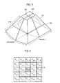
FIG. 5 is a schematic diagram showing an example of the volume data. The volume data VD include a plurality of voxels (not shown) having brightness values. InFIG. 5 ,reference numerals A plane 521, theB plane 522 and theC plane 523 are mutually orthogonal. Also, inFIG. 5 , the axial direction is a transmitting direction of the ultrasound signals, the lateral direction is a longitudinal direction of the elements, and the elevation direction is a swing direction of the elements, i.e., a depth direction of the three-dimensional ultrasound image. - Referring back to
FIG. 4 , theprocessing unit 130 is configured to perform volume-rendering upon the volume data VD to calculate intensity accumulation values throughout the depth, at step S404 inFIG. 4 . Volume-rendering includes ray-casting for emitting virtual rays to the volume data VD. - In one embodiment, the
processing unit 130 accumulates intensity values of sample points on each of the virtual rays based on transparency (or opacity) of the sample points to calculate the intensity accumulation values throughout the depth asequation 1 provided below.
- In
equation 1, I represents intensity, and T represents transparency. - The
processing unit 130 is configured to perform ray-casting upon the volume data VD to calculate depth accumulation values throughout the depth, at step S406 inFIG. 4 . Theprocessing unit 130 is configured to form a depth information image based on the depth accumulation values, at step S408 inFIG. 4 . The methods of forming the depth information image are well known in the art. Thus, they have not been described in detail so as not to unnecessarily obscure the present disclosure. - In one embodiment, the
processing unit 130 accumulates depth values of the sample points on each of the virtual rays based on transparency (or opacity) of the sample points to calculate the depth accumulation values throughout the depth asequation 2 provided below.
- In
equation 2, D represents depth, and T represents transparency. - The
processing unit 130 is configured to calculate gradient intensity based on the depth information image, at step S410 inFIG. 4 . Generally, the depth information image is regarded as a surface having a height value corresponding to each of the pixels, and the gradient in the three-dimensional volume is regarded as a normal of the surface. - In one embodiment, the
processing unit 130 sets a window W on the adjacent pixels P2,2, P2,3, P2,4, P3,2, P3,4, P4,2, P4,3 and P4,4 based on a pixel P3,3 as shown inFIG. 6 . Theprocessing unit 130 further sets a center point corresponding to each of pixels within the window W as shown inFIG. 7 . Theprocessing unit 130 further sets polygons PG1 to PG8 for connecting the adjacent pixels based on the center points. Theprocessing unit 130 further calculates normals N1 to N8 corresponding to the polygons PG1 to PG8. The methods of calculating the normal are well known in the art. Thus, they have not been described in detail so as not to unnecessarily obscure the present disclosure. Theprocessing unit 130 further calculates a mean normal of the calculated normals to N8. Theprocessing unit 130 further sets the calculated mean normal as the surface normal (i.e., gradient intensity) of the pixel P3,3. - Although it is described that the
processing unit 130sets 8 pixels as the adjacent pixels based on the each of the pixels, the number of the adjacent pixels may not be limited thereto. Also, although it is described that the polygons for connecting the adjacent pixels are a triangle, the polygons may not be limited thereto. - The
processing unit 130 is configured to calculate shading values based on the surface normals and the virtual rays, at step S412 inFIG. 4 . In one embodiment, theprocessing unit 130 calculates scalar product values between vectors of the surface normals and vectors of the virtual rays as the shading values. - The
processing unit 130 is configured to form the three-dimensional color reference table based on the intensity accumulation values and the shading values, at step S414 inFIG. 4 . In one embodiment, theprocessing unit 130 forms the three-dimensional color reference. The three-dimensional color reference table is stored in thestorage unit 120. - Optionally, the
processing unit 130 is configured to analyze the volume data VD to detect a skin tone of the target object (eg., a fetus). Theprocessing unit 130 is further configured to apply the detected skin tone to the three-dimensional color reference table. The methods of detecting the skin tone are well known in the art. Thus, they have not been described in detail so as not to unnecessarily obscure the present disclosure. -
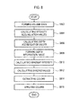
FIG. 8 is a flow chart showing a process of forming a three-dimensional ultrasound image. Theprocessing unit 130 is configured to form the volume data VD as shown inFIG. 5 based on the ultrasound data newly provided from the ultrasounddata acquisition unit 110, at step S802 inFIG. 8 . - The
processing unit 130 is configured to perform volume rendering (i.e., ray-casting) upon the volume data VD to calculate the intensity accumulation values throughout the depth, at step S804 inFIG. 8 . Theprocessing unit 130 is configured to perform ray-casting upon the volume data VD to form the depth accumulation values throughout the depth, at step S806 inFIG. 8 . Theprocessing unit 130 is configured to form the depth information image based on the depth accumulation values, at step S808 inFIG. 8 . Theprocessing unit 130 is configured to the gradient intensity based on the depth information image, at step S810 inFIG. 8 . Theprocessing unit 130 is configured to calculate the shading values based on the surface normals and the virtual rays, at step S812 inFIG. 8 . - The
processing unit 130 is configured to retrieve the three-dimensional color reference table stored in thestorage unit 120 to extract colors corresponding to the intensity accumulation values and the shading values throughout the depth, at step S814 inFIG. 8 . - Optionally, the
processing unit 130 is configured to analyze the volume data VD to detect the skin tone of the target object (e.g., fetus). Theprocessing unit 130 is further configured to retrieve the three-dimensional color reference table to extract colors corresponding to the skin tone. - Also, the
processing unit 130 is configured to detect the skin tone (e.g., fetus) of the target object based on input information provided from a user input unit (not shown). The input information is skin tone selection information for selecting the skin tone of parents or a race. - The
processing unit 130 is configured to apply the extracted colors to the volume data VD to form a three-dimensional ultrasound image, at step S816 inFIG. 8 . In one embodiment, theprocessing unit 130 applies the extracted colors to the voxels corresponding to the depth of the volume data VD to form the three-dimensional ultrasound image. - Referring back to
FIG. 1 , theultrasound system 100 further includes adisplay unit 140. Thedisplay unit 140 is configured to display the three-dimensional ultrasound image formed by theprocessing unit 130. Thedisplay unit 140 includes a cathode ray tube, a liquid crystal display, a light emitting diode, an organic light emitting diode and the like. - Although embodiments have been described with reference to a number of illustrative embodiments thereof, it should be understood that numerous other modifications and embodiments can be devised by those skilled in the art that will fall within the scope of the principles of this disclosure. More particularly, numerous variations and modifications are possible in the component parts and/or arrangements of the subject combination arrangement within the scope of the disclosure, the drawings and the appended claims. In addition to variations and modifications in the component parts and/or arrangements, alternative uses will also be apparent to those skilled in the art.
Claims (15)
- An ultrasound system, comprising:a storage unit for storing a three-dimensional color reference table for providing colors corresponding to at least one of intensity accumulation values and shading values throughout depth; anda processing unit configured to form volume data based on ultrasound data corresponding to a target object and perform ray-casting on the volume data to calculate intensity accumulation values and shading values throughout the depth, the processing unit being further configured to apply colors corresponding to the at least one of the calculated intensity accumulation values and the calculated shading values based on the three-dimensional color reference table.
- The ultrasound system of Claim 1, wherein the processing unit is configured to form the three-dimensional color reference table based on the volume data.
- The ultrasound system of Claim 2, wherein the processing unit is configured to:perform ray-casting for emitting virtual rays upon volume data to calculate the intensity accumulation values and depth accumulation values throughout the depth;form a depth information image based on the depth accumulation values;calculate gradient intensity based on the depth information image;calculate the shading values based on the gradient intensity; andform the three-dimensional color reference table based on the depth, the intensity accumulation values and the shading values.
- The ultrasound system of Claim 3, wherein the processing unit is configured to:set a window on adjacent pixels based on each of the pixels of the depth information image;set a center point of each of the pixels within the windows;set a plurality of polygons for connecting adjacent pixels based on the center points;calculate a plurality of normals corresponding to the plurality of polygons;calculate a mean normal of the normals;calculate the gradient intensity of a surface normal corresponding to each of the pixels of the depth information image based on the mean normal; andcalculate scalar product values between vectors of the surface normals and vectors of the virtual rays as the shading value.
- The ultrasound system of Claim 3, wherein the processing unit is further configured to:analyze the volume data to detect a skin tone of the target object; andapply the detected skin tone to the three-dimensional color reference table.
- The ultrasound system of Claim 1, wherein the processing unit is configured to:perform ray-casting for emitting virtual rays upon the volume data to calculate the intensity accumulation values and depth accumulation values throughout the depth;form a depth information image based on the depth accumulation values;calculate gradient intensity based on the depth information image;calculate scalar product values between vectors of the surface normals and vectors of the virtual rays as the shading value based on the gradient intensity;retrieve the three-dimensional color reference table to extract the colors corresponding to the intensity accumulation values and the shading values; andapply the extracted colors to the volume data to form the three-dimensional ultrasound image.
- The ultrasound system of Claim 6, wherein the processing unit is further configured to:analyze the volume data to detect the skin tone of the target object;retrieve the three-dimensional color reference table to extract colors corresponding to the skin tone; andapply the extracted colors to the volume data.
- A method of providing a three-dimensional ultrasound image, comprising:a) forming volume data based on ultrasound data corresponding to a target object;b) performing ray-casting on the volume data to calculate intensity accumulation values and shading values throughout the depth; andc) applying colors corresponding to the at least one of the calculated intensity accumulation values and the calculated shading values based on a three-dimensional color reference table for providing colors corresponding to at least one of intensity accumulation values and shading values throughout depth.
- The method of Claim 8, further comprising:forming the three-dimensional color reference table based on the volume data, prior to performing the step a).
- The method of Claim 9, wherein the step of forming the three-dimensional color reference table comprises:performing ray-casting for emitting virtual rays upon volume data to calculate the intensity accumulation values and depth accumulation values throughout the depth;forming a depth information image based on the depth accumulation values;calculating gradient intensity based on the depth information image;calculating the shading values based on the gradient intensity; andforming the three-dimensional color reference table based on the depth, the intensity accumulation values and the shading values.
- The method of Claim 10, wherein calculating gradient intensities comprises:setting a window on adjacent pixels based on each of pixels of the depth information image;setting a center point of each of the pixels within the windows;setting a plurality of polygons for connecting adjacent pixels based on the center points;calculating a plurality of normals corresponding to the plurality of polygons;calculating a mean normal of the normals; andcalculating the gradient intensity of a surface normal corresponding to each of the pixels of the depth information image based on the mean normal.
- The method of Claim 11, wherein calculating the shading values comprises:calculating scalar product values between vectors of the surface normals and vectors of the virtual rays as the shading value.
- The method of Claim 12, wherein the step of forming the three-dimensional color reference table further comprises:analyzing the volume data to detect a skin tone of the target object; andapplying the detected skin tone to the three-dimensional color reference table.
- The method of Claim 8, wherein the step c) comprises:c1) performing ray-casting for emitting virtual rays upon the volume data to calculate the intensity accumulation values and depth accumulation values throughout the depth;c2) forming a depth information image based on the depth accumulation values;c3) calculating gradient intensity based on the depth information image;c4) calculating scalar product values between vectors of the surface normals and vectors of the virtual rays as the shading value based on the gradient intensity;c5) retrieving the three-dimensional color reference table to extract the colors corresponding to the intensity accumulation values and the shading values; andc6) applying the extracted colors to the volume data to form the three-dimensional ultrasound image.
- The method of Claim 14, wherein the step c) further comprises:analyzing the volume data to detect the skin tone of the target object;retrieving the three-dimensional color reference table to extract colors corresponding to the skin tone; andapplying the extracted colors to the volume data.
Applications Claiming Priority (1)
| Application Number | Priority Date | Filing Date | Title |
|---|---|---|---|
| KR20110033913 | 2011-04-12 |
Publications (2)
| Publication Number | Publication Date |
|---|---|
| EP2511878A1 true EP2511878A1 (en) | 2012-10-17 |
| EP2511878B1 EP2511878B1 (en) | 2020-05-06 |
Family
ID=45977241
Family Applications (1)
| Application Number | Title | Priority Date | Filing Date |
|---|---|---|---|
| EP12163628.6A Active EP2511878B1 (en) | 2011-04-12 | 2012-04-10 | Providing three-dimensional ultrasound image based on three-dimensional color reference table in ultrasound system |
Country Status (3)
| Country | Link |
|---|---|
| US (1) | US20120265074A1 (en) |
| EP (1) | EP2511878B1 (en) |
| KR (1) | KR101478622B1 (en) |
Cited By (1)
| Publication number | Priority date | Publication date | Assignee | Title |
|---|---|---|---|---|
| CN109583340A (en) * | 2018-11-15 | 2019-04-05 | 中山大学 | A kind of video object detection method based on deep learning |
Families Citing this family (11)
| Publication number | Priority date | Publication date | Assignee | Title |
|---|---|---|---|---|
| US10667790B2 (en) | 2012-03-26 | 2020-06-02 | Teratech Corporation | Tablet ultrasound system |
| US9877699B2 (en) | 2012-03-26 | 2018-01-30 | Teratech Corporation | Tablet ultrasound system |
| KR101524085B1 (en) * | 2013-01-04 | 2015-05-29 | 삼성메디슨 주식회사 | Apparatus and method for providing medical image |
| KR102377530B1 (en) * | 2013-09-30 | 2022-03-23 | 삼성메디슨 주식회사 | The method and apparatus for generating three-dimensional(3d) image of the object |
| KR20150064937A (en) | 2013-12-04 | 2015-06-12 | 삼성전자주식회사 | Image processing apparatus and image processing method |
| CN110167449A (en) | 2016-11-16 | 2019-08-23 | 德拉工业公司 | Portable ultrasound system |
| US10453193B2 (en) * | 2017-05-05 | 2019-10-22 | General Electric Company | Methods and system for shading a two-dimensional ultrasound image |
| US10489969B2 (en) | 2017-11-08 | 2019-11-26 | General Electric Company | Method and system for presenting shaded descriptors corresponding with shaded ultrasound images |
| JP7078457B2 (en) * | 2018-05-29 | 2022-05-31 | 富士フイルムヘルスケア株式会社 | Blood flow image processing device and method |
| JP6924236B2 (en) * | 2019-09-26 | 2021-08-25 | ゼネラル・エレクトリック・カンパニイ | Ultrasonic diagnostic equipment and its control program |
| CN116342792B (en) * | 2021-12-22 | 2026-04-21 | 深圳开立生物医疗科技股份有限公司 | Ultrasonic imaging methods, devices, ultrasonic equipment and readable storage media |
Citations (1)
| Publication number | Priority date | Publication date | Assignee | Title |
|---|---|---|---|---|
| US20020172409A1 (en) * | 2001-05-18 | 2002-11-21 | Motoaki Saito | Displaying three-dimensional medical images |
Family Cites Families (11)
| Publication number | Priority date | Publication date | Assignee | Title |
|---|---|---|---|---|
| US6559843B1 (en) * | 1993-10-01 | 2003-05-06 | Compaq Computer Corporation | Segmented ray casting data parallel volume rendering |
| US6116244A (en) * | 1998-06-02 | 2000-09-12 | Acuson Corporation | Ultrasonic system and method for three-dimensional imaging with opacity control |
| US6525740B1 (en) * | 1999-03-18 | 2003-02-25 | Evans & Sutherland Computer Corporation | System and method for antialiasing bump texture and bump mapping |
| AU2002366321A1 (en) * | 2001-12-14 | 2003-06-30 | Koninklijke Philips Electronics N.V. | Method, system and computer program of visualizing the surface texture of the wall of an internal hollow organ of a subject based on a volumetric scan thereof |
| US20060056680A1 (en) * | 2004-09-13 | 2006-03-16 | Sandy Stutsman | 3D volume construction from DICOM data |
| KR101055588B1 (en) * | 2007-09-04 | 2011-08-23 | 삼성메디슨 주식회사 | Ultrasound System and Method for Forming Ultrasound Images |
| US9336624B2 (en) * | 2008-10-07 | 2016-05-10 | Mitsubishi Electric Research Laboratories, Inc. | Method and system for rendering 3D distance fields |
| US20110090222A1 (en) * | 2009-10-15 | 2011-04-21 | Siemens Corporation | Visualization of scaring on cardiac surface |
| KR101028353B1 (en) | 2009-12-09 | 2011-06-14 | 주식회사 메디슨 | Ultrasound system and method for performing image optimization |
| US8582865B2 (en) * | 2010-04-28 | 2013-11-12 | General Electric Company | Ultrasound imaging with ray casting and software-based image reconstruction |
| US9544577B2 (en) * | 2013-07-18 | 2017-01-10 | A.Tron3D Gmbh | Method of capturing three-dimensional (3D) information on a structure |
-
2012
- 2012-04-10 EP EP12163628.6A patent/EP2511878B1/en active Active
- 2012-04-12 US US13/445,505 patent/US20120265074A1/en not_active Abandoned
- 2012-04-12 KR KR20120038013A patent/KR101478622B1/en active Active
Patent Citations (1)
| Publication number | Priority date | Publication date | Assignee | Title |
|---|---|---|---|---|
| US20020172409A1 (en) * | 2001-05-18 | 2002-11-21 | Motoaki Saito | Displaying three-dimensional medical images |
Non-Patent Citations (5)
| Title |
|---|
| ALAN WATT: "3D Computer Graphics, Third Edition", 2000, ADDISON WESLEY, London, XP002681439 * |
| HÖNIGMANN D ET AL: "Adaptive design of a global opacity transfer function for direct volume rendering of ultrasound data", VIS 2003. IEEE VISUALIZATION 2003. PROCEEDINGS. SEATTLE, WA, OCT. 19 - 24, 2003; [ANNUAL IEEE CONFERENCE ON VISUALIZATION], NEW YORK, NY : IEEE, US, 1 January 2003 (2003-01-01), pages 489 - 496, XP031173536, ISBN: 978-0-7803-8120-9, DOI: 10.1109/VISUAL.2003.1250411 * |
| LEVOY M: "Display of surfaces from volume data", IEEE COMPUTER GRAPHICS AND APPLICATIONS, IEEE SERVICE CENTER, NEW YORK, NY, US, vol. 8, no. 3, 1 May 1988 (1988-05-01), pages 29 - 37, XP011413670, ISSN: 0272-1716, DOI: 10.1109/38.511 * |
| ROBB R A: "Visualization in biomedical computing", PARALLEL COMPUTING, ELSEVIER PUBLISHERS, AMSTERDAM, NL, vol. 25, no. 13-14, 1 December 1999 (1999-12-01), pages 2067 - 2110, XP004363672, ISSN: 0167-8191, DOI: 10.1016/S0167-8191(99)00076-9 * |
| ZIV SOFERMAN ET AL: "Advanced Graphics Behind Medical Virtual Reality: Evolution of Algorithms, Hardware, and Software Interfaces", PROCEEDINGS OF THE IEEE, IEEE. NEW YORK, US, vol. 86, no. 3, 1 March 1998 (1998-03-01), XP011043998, ISSN: 0018-9219 * |
Cited By (1)
| Publication number | Priority date | Publication date | Assignee | Title |
|---|---|---|---|---|
| CN109583340A (en) * | 2018-11-15 | 2019-04-05 | 中山大学 | A kind of video object detection method based on deep learning |
Also Published As
| Publication number | Publication date |
|---|---|
| EP2511878B1 (en) | 2020-05-06 |
| US20120265074A1 (en) | 2012-10-18 |
| KR101478622B1 (en) | 2015-01-02 |
| KR20120116364A (en) | 2012-10-22 |
Similar Documents
| Publication | Publication Date | Title |
|---|---|---|
| EP2511878B1 (en) | Providing three-dimensional ultrasound image based on three-dimensional color reference table in ultrasound system | |
| US9220441B2 (en) | Medical system and method for providing measurement information using three-dimensional caliper | |
| US8795178B2 (en) | Ultrasound imaging system and method for identifying data from a shadow region | |
| KR102539901B1 (en) | Methods and system for shading a two-dimensional ultrasound image | |
| US10878565B2 (en) | Analyzing apparatus and analyzing method | |
| US8900147B2 (en) | Performing image process and size measurement upon a three-dimensional ultrasound image in an ultrasound system | |
| US10499879B2 (en) | Systems and methods for displaying intersections on ultrasound images | |
| US9261485B2 (en) | Providing color doppler image based on qualification curve information in ultrasound system | |
| KR101579740B1 (en) | Untrasound dianognosis apparatus, method and computer-readable storage medium | |
| US20120154400A1 (en) | Method of reducing noise in a volume-rendered image | |
| US9069062B2 (en) | Surface rendering for volume data in an ultrasound system | |
| EP2333576A2 (en) | Providing a three-dimensional ultrasound image based on a sub region of interest in an ultrasound system | |
| US20120190984A1 (en) | Ultrasound system with opacity setting unit | |
| US9078590B2 (en) | Providing additional information corresponding to change of blood flow with a time in ultrasound system | |
| EP2333724A2 (en) | Providing an ultrasound spatial compound image in an ultrasound system | |
| US20110142319A1 (en) | Providing multiple 3-dimensional ultrasound images in an ultrasound image | |
| EP2425784B1 (en) | Providing a color Doppler mode image in an ultrasound system | |
| KR102321853B1 (en) | Method and system for enhanced visualization of moving structures with cross-plane ultrasound images | |
| US10489969B2 (en) | Method and system for presenting shaded descriptors corresponding with shaded ultrasound images | |
| EP2446827A1 (en) | Providing a body mark in an ultrasound system | |
| EP2386251A1 (en) | Providing at least one slice image with additional information in an ultrasound system | |
| EP2422704A2 (en) | Providing ultrasound spatial compound images in an ultrasound system |
Legal Events
| Date | Code | Title | Description |
|---|---|---|---|
| PUAI | Public reference made under article 153(3) epc to a published international application that has entered the european phase |
Free format text: ORIGINAL CODE: 0009012 |
|
| AK | Designated contracting states |
Kind code of ref document: A1 Designated state(s): AL AT BE BG CH CY CZ DE DK EE ES FI FR GB GR HR HU IE IS IT LI LT LU LV MC MK MT NL NO PL PT RO RS SE SI SK SM TR |
|
| AX | Request for extension of the european patent |
Extension state: BA ME |
|
| 17P | Request for examination filed |
Effective date: 20130417 |
|
| 17Q | First examination report despatched |
Effective date: 20140910 |
|
| STAA | Information on the status of an ep patent application or granted ep patent |
Free format text: STATUS: EXAMINATION IS IN PROGRESS |
|
| GRAP | Despatch of communication of intention to grant a patent |
Free format text: ORIGINAL CODE: EPIDOSNIGR1 |
|
| STAA | Information on the status of an ep patent application or granted ep patent |
Free format text: STATUS: GRANT OF PATENT IS INTENDED |
|
| INTG | Intention to grant announced |
Effective date: 20191220 |
|
| RIN1 | Information on inventor provided before grant (corrected) |
Inventor name: KIM, SUNG YUN Inventor name: NA, KYUNG GUN |
|
| GRAS | Grant fee paid |
Free format text: ORIGINAL CODE: EPIDOSNIGR3 |
|
| GRAA | (expected) grant |
Free format text: ORIGINAL CODE: 0009210 |
|
| STAA | Information on the status of an ep patent application or granted ep patent |
Free format text: STATUS: THE PATENT HAS BEEN GRANTED |
|
| AK | Designated contracting states |
Kind code of ref document: B1 Designated state(s): AL AT BE BG CH CY CZ DE DK EE ES FI FR GB GR HR HU IE IS IT LI LT LU LV MC MK MT NL NO PL PT RO RS SE SI SK SM TR |
|
| REG | Reference to a national code |
Ref country code: GB Ref legal event code: FG4D |
|
| REG | Reference to a national code |
Ref country code: AT Ref legal event code: REF Ref document number: 1268018 Country of ref document: AT Kind code of ref document: T Effective date: 20200515 Ref country code: CH Ref legal event code: EP |
|
| REG | Reference to a national code |
Ref country code: IE Ref legal event code: FG4D |
|
| REG | Reference to a national code |
Ref country code: DE Ref legal event code: R096 Ref document number: 602012069818 Country of ref document: DE |
|
| REG | Reference to a national code |
Ref country code: LT Ref legal event code: MG4D |
|
| REG | Reference to a national code |
Ref country code: NL Ref legal event code: MP Effective date: 20200506 |
|
| PG25 | Lapsed in a contracting state [announced via postgrant information from national office to epo] |
Ref country code: IS Free format text: LAPSE BECAUSE OF FAILURE TO SUBMIT A TRANSLATION OF THE DESCRIPTION OR TO PAY THE FEE WITHIN THE PRESCRIBED TIME-LIMIT Effective date: 20200906 Ref country code: FI Free format text: LAPSE BECAUSE OF FAILURE TO SUBMIT A TRANSLATION OF THE DESCRIPTION OR TO PAY THE FEE WITHIN THE PRESCRIBED TIME-LIMIT Effective date: 20200506 Ref country code: GR Free format text: LAPSE BECAUSE OF FAILURE TO SUBMIT A TRANSLATION OF THE DESCRIPTION OR TO PAY THE FEE WITHIN THE PRESCRIBED TIME-LIMIT Effective date: 20200807 Ref country code: PT Free format text: LAPSE BECAUSE OF FAILURE TO SUBMIT A TRANSLATION OF THE DESCRIPTION OR TO PAY THE FEE WITHIN THE PRESCRIBED TIME-LIMIT Effective date: 20200907 Ref country code: NO Free format text: LAPSE BECAUSE OF FAILURE TO SUBMIT A TRANSLATION OF THE DESCRIPTION OR TO PAY THE FEE WITHIN THE PRESCRIBED TIME-LIMIT Effective date: 20200806 Ref country code: LT Free format text: LAPSE BECAUSE OF FAILURE TO SUBMIT A TRANSLATION OF THE DESCRIPTION OR TO PAY THE FEE WITHIN THE PRESCRIBED TIME-LIMIT Effective date: 20200506 Ref country code: SE Free format text: LAPSE BECAUSE OF FAILURE TO SUBMIT A TRANSLATION OF THE DESCRIPTION OR TO PAY THE FEE WITHIN THE PRESCRIBED TIME-LIMIT Effective date: 20200506 |
|
| PG25 | Lapsed in a contracting state [announced via postgrant information from national office to epo] |
Ref country code: LV Free format text: LAPSE BECAUSE OF FAILURE TO SUBMIT A TRANSLATION OF THE DESCRIPTION OR TO PAY THE FEE WITHIN THE PRESCRIBED TIME-LIMIT Effective date: 20200506 Ref country code: RS Free format text: LAPSE BECAUSE OF FAILURE TO SUBMIT A TRANSLATION OF THE DESCRIPTION OR TO PAY THE FEE WITHIN THE PRESCRIBED TIME-LIMIT Effective date: 20200506 Ref country code: HR Free format text: LAPSE BECAUSE OF FAILURE TO SUBMIT A TRANSLATION OF THE DESCRIPTION OR TO PAY THE FEE WITHIN THE PRESCRIBED TIME-LIMIT Effective date: 20200506 Ref country code: BG Free format text: LAPSE BECAUSE OF FAILURE TO SUBMIT A TRANSLATION OF THE DESCRIPTION OR TO PAY THE FEE WITHIN THE PRESCRIBED TIME-LIMIT Effective date: 20200806 |
|
| REG | Reference to a national code |
Ref country code: AT Ref legal event code: MK05 Ref document number: 1268018 Country of ref document: AT Kind code of ref document: T Effective date: 20200506 |
|
| PG25 | Lapsed in a contracting state [announced via postgrant information from national office to epo] |
Ref country code: NL Free format text: LAPSE BECAUSE OF FAILURE TO SUBMIT A TRANSLATION OF THE DESCRIPTION OR TO PAY THE FEE WITHIN THE PRESCRIBED TIME-LIMIT Effective date: 20200506 Ref country code: AL Free format text: LAPSE BECAUSE OF FAILURE TO SUBMIT A TRANSLATION OF THE DESCRIPTION OR TO PAY THE FEE WITHIN THE PRESCRIBED TIME-LIMIT Effective date: 20200506 |
|
| PG25 | Lapsed in a contracting state [announced via postgrant information from national office to epo] |
Ref country code: DK Free format text: LAPSE BECAUSE OF FAILURE TO SUBMIT A TRANSLATION OF THE DESCRIPTION OR TO PAY THE FEE WITHIN THE PRESCRIBED TIME-LIMIT Effective date: 20200506 Ref country code: EE Free format text: LAPSE BECAUSE OF FAILURE TO SUBMIT A TRANSLATION OF THE DESCRIPTION OR TO PAY THE FEE WITHIN THE PRESCRIBED TIME-LIMIT Effective date: 20200506 Ref country code: SM Free format text: LAPSE BECAUSE OF FAILURE TO SUBMIT A TRANSLATION OF THE DESCRIPTION OR TO PAY THE FEE WITHIN THE PRESCRIBED TIME-LIMIT Effective date: 20200506 Ref country code: AT Free format text: LAPSE BECAUSE OF FAILURE TO SUBMIT A TRANSLATION OF THE DESCRIPTION OR TO PAY THE FEE WITHIN THE PRESCRIBED TIME-LIMIT Effective date: 20200506 Ref country code: ES Free format text: LAPSE BECAUSE OF FAILURE TO SUBMIT A TRANSLATION OF THE DESCRIPTION OR TO PAY THE FEE WITHIN THE PRESCRIBED TIME-LIMIT Effective date: 20200506 Ref country code: CZ Free format text: LAPSE BECAUSE OF FAILURE TO SUBMIT A TRANSLATION OF THE DESCRIPTION OR TO PAY THE FEE WITHIN THE PRESCRIBED TIME-LIMIT Effective date: 20200506 Ref country code: RO Free format text: LAPSE BECAUSE OF FAILURE TO SUBMIT A TRANSLATION OF THE DESCRIPTION OR TO PAY THE FEE WITHIN THE PRESCRIBED TIME-LIMIT Effective date: 20200506 |
|
| REG | Reference to a national code |
Ref country code: DE Ref legal event code: R097 Ref document number: 602012069818 Country of ref document: DE |
|
| PG25 | Lapsed in a contracting state [announced via postgrant information from national office to epo] |
Ref country code: PL Free format text: LAPSE BECAUSE OF FAILURE TO SUBMIT A TRANSLATION OF THE DESCRIPTION OR TO PAY THE FEE WITHIN THE PRESCRIBED TIME-LIMIT Effective date: 20200506 Ref country code: SK Free format text: LAPSE BECAUSE OF FAILURE TO SUBMIT A TRANSLATION OF THE DESCRIPTION OR TO PAY THE FEE WITHIN THE PRESCRIBED TIME-LIMIT Effective date: 20200506 |
|
| PLBE | No opposition filed within time limit |
Free format text: ORIGINAL CODE: 0009261 |
|
| STAA | Information on the status of an ep patent application or granted ep patent |
Free format text: STATUS: NO OPPOSITION FILED WITHIN TIME LIMIT |
|
| 26N | No opposition filed |
Effective date: 20210209 |
|
| PG25 | Lapsed in a contracting state [announced via postgrant information from national office to epo] |
Ref country code: SI Free format text: LAPSE BECAUSE OF FAILURE TO SUBMIT A TRANSLATION OF THE DESCRIPTION OR TO PAY THE FEE WITHIN THE PRESCRIBED TIME-LIMIT Effective date: 20200506 |
|
| PG25 | Lapsed in a contracting state [announced via postgrant information from national office to epo] |
Ref country code: MC Free format text: LAPSE BECAUSE OF FAILURE TO SUBMIT A TRANSLATION OF THE DESCRIPTION OR TO PAY THE FEE WITHIN THE PRESCRIBED TIME-LIMIT Effective date: 20200506 |
|
| GBPC | Gb: european patent ceased through non-payment of renewal fee |
Effective date: 20210410 |
|
| PG25 | Lapsed in a contracting state [announced via postgrant information from national office to epo] |
Ref country code: LU Free format text: LAPSE BECAUSE OF NON-PAYMENT OF DUE FEES Effective date: 20210410 |
|
| REG | Reference to a national code |
Ref country code: BE Ref legal event code: MM Effective date: 20210430 |
|
| PG25 | Lapsed in a contracting state [announced via postgrant information from national office to epo] |
Ref country code: GB Free format text: LAPSE BECAUSE OF NON-PAYMENT OF DUE FEES Effective date: 20210410 Ref country code: CH Free format text: LAPSE BECAUSE OF NON-PAYMENT OF DUE FEES Effective date: 20210430 Ref country code: LI Free format text: LAPSE BECAUSE OF NON-PAYMENT OF DUE FEES Effective date: 20210430 |
|
| PG25 | Lapsed in a contracting state [announced via postgrant information from national office to epo] |
Ref country code: IE Free format text: LAPSE BECAUSE OF NON-PAYMENT OF DUE FEES Effective date: 20210410 |
|
| PG25 | Lapsed in a contracting state [announced via postgrant information from national office to epo] |
Ref country code: BE Free format text: LAPSE BECAUSE OF NON-PAYMENT OF DUE FEES Effective date: 20210430 |
|
| PG25 | Lapsed in a contracting state [announced via postgrant information from national office to epo] |
Ref country code: HU Free format text: LAPSE BECAUSE OF FAILURE TO SUBMIT A TRANSLATION OF THE DESCRIPTION OR TO PAY THE FEE WITHIN THE PRESCRIBED TIME-LIMIT; INVALID AB INITIO Effective date: 20120410 Ref country code: CY Free format text: LAPSE BECAUSE OF FAILURE TO SUBMIT A TRANSLATION OF THE DESCRIPTION OR TO PAY THE FEE WITHIN THE PRESCRIBED TIME-LIMIT Effective date: 20200506 |
|
| PG25 | Lapsed in a contracting state [announced via postgrant information from national office to epo] |
Ref country code: MK Free format text: LAPSE BECAUSE OF FAILURE TO SUBMIT A TRANSLATION OF THE DESCRIPTION OR TO PAY THE FEE WITHIN THE PRESCRIBED TIME-LIMIT Effective date: 20200506 |
|
| PG25 | Lapsed in a contracting state [announced via postgrant information from national office to epo] |
Ref country code: TR Free format text: LAPSE BECAUSE OF FAILURE TO SUBMIT A TRANSLATION OF THE DESCRIPTION OR TO PAY THE FEE WITHIN THE PRESCRIBED TIME-LIMIT Effective date: 20200506 |
|
| PG25 | Lapsed in a contracting state [announced via postgrant information from national office to epo] |
Ref country code: MT Free format text: LAPSE BECAUSE OF FAILURE TO SUBMIT A TRANSLATION OF THE DESCRIPTION OR TO PAY THE FEE WITHIN THE PRESCRIBED TIME-LIMIT Effective date: 20200506 |
|
| PGFP | Annual fee paid to national office [announced via postgrant information from national office to epo] |
Ref country code: FR Payment date: 20250307 Year of fee payment: 14 |
|
| PGFP | Annual fee paid to national office [announced via postgrant information from national office to epo] |
Ref country code: IT Payment date: 20250306 Year of fee payment: 14 |
|
| PGFP | Annual fee paid to national office [announced via postgrant information from national office to epo] |
Ref country code: DE Payment date: 20250305 Year of fee payment: 14 |