EP2511841A2 - System and method for generation of cim-based power system circuit models - Google Patents
System and method for generation of cim-based power system circuit models Download PDFInfo
- Publication number
- EP2511841A2 EP2511841A2 EP12163130A EP12163130A EP2511841A2 EP 2511841 A2 EP2511841 A2 EP 2511841A2 EP 12163130 A EP12163130 A EP 12163130A EP 12163130 A EP12163130 A EP 12163130A EP 2511841 A2 EP2511841 A2 EP 2511841A2
- Authority
- EP
- European Patent Office
- Prior art keywords
- cim
- circuit
- based circuit
- model
- generating
- Prior art date
- Legal status (The legal status is an assumption and is not a legal conclusion. Google has not performed a legal analysis and makes no representation as to the accuracy of the status listed.)
- Withdrawn
Links
Images



Classifications
-
- G—PHYSICS
- G06—COMPUTING OR CALCULATING; COUNTING
- G06F—ELECTRIC DIGITAL DATA PROCESSING
- G06F30/00—Computer-aided design [CAD]
- G06F30/30—Circuit design
- G06F30/39—Circuit design at the physical level
- G06F30/394—Routing
-
- G—PHYSICS
- G06—COMPUTING OR CALCULATING; COUNTING
- G06F—ELECTRIC DIGITAL DATA PROCESSING
- G06F30/00—Computer-aided design [CAD]
- G06F30/30—Circuit design
-
- G—PHYSICS
- G06—COMPUTING OR CALCULATING; COUNTING
- G06F—ELECTRIC DIGITAL DATA PROCESSING
- G06F30/00—Computer-aided design [CAD]
- G06F30/20—Design optimisation, verification or simulation
-
- G—PHYSICS
- G06—COMPUTING OR CALCULATING; COUNTING
- G06F—ELECTRIC DIGITAL DATA PROCESSING
- G06F2119/00—Details relating to the type or aim of the analysis or the optimisation
- G06F2119/06—Power analysis or power optimisation
Definitions
- the present disclosure relates generally to a common information model (CIM) based circuit model generator and more particularly to a CIM-based circuit model generator that generates valid CIM-based circuit models from simplified circuit definitions.
- CIM common information model
- Power system circuit models are typically developed for use by power system software to test various parameters and scenarios of a power system.
- the standard model known as the common information model (CIM) provides an open standard that defines how many typical objects used in power systems, such as transformers, buses, breakers, and other suitable objects, are represented in a power system circuit model.
- CIM-based circuit models can be used across multiple different power system testing platforms and can facilitate the exchange of circuit models and circuit data between multiple entities.
- CIM-based circuit models can be difficult and time consuming.
- the generation of a CIM-based circuit model can require the creation and manipulation of extensible markup language (XML) files.
- XML extensible markup language
- the generation of a CIM-based circuit model can require that all CIM objects be specified.
- a CIM-based model connection between one or more circuit objects requires specification of details such as terminals, connectivity nodes, line segments, and other CIM objects.
- the time necessary to generate CIM-based circuit models can lead to decreased productivity and delay in testing of power system scenarios.
- a system and method for generating CIM-based circuit models from simplified circuit definitions would be welcome in the art.
- a system and method that would provide for the automatic generation of objects required by the CIM model that are not essential for the particular testing purposes of an individual circuit, such as terminals, line segments, connectivity nodes, and other objects, would be particularly useful.
- the present invention is directed to a method for generating a common information model (CIM) based circuit model.
- the method includes receiving a circuit representation file specifying attributes of one or more circuit elements.
- the method further includes generating with a computing device a CIM-based circuit model from the circuit representation file.
- the CIM-based circuit model includes a first CIM-based circuit object and a second CIM-based circuit object.
- the first and second CIM-based circuit objects are generated based at least in part on attributes specified in the circuit representation file.
- the method further includes generating with the computing device an unspecified CIM required connection in the CIM-based circuit model between the first CIM-based circuit object and the second CIM-based circuit object.
- the circuit representation file does not specify at least one attribute of the CIM required connection.
- the invention also resides in a computer program comprising computer program code adapted to perform the steps of the above method when run on a computer.
- the present invention is also directed to a computer-based system for generating a common information model (CIM) based circuit model.
- the system includes at least one processing device and at least one memory including the computer program described above embodied on a computer readable medium.
- the present disclosure is directed to systems and methods for generating common information model (CIM) based models of power systems to be used as a testing framework for power system software applications.
- CIM-based circuit models can be constructed from simplified circuit definitions.
- CIM objects required by the CIM model that are not essential for the testing purposes of an individual circuit such as terminals, line segments, connectivity nodes, and other CIM objects, are generated automatically and are not required in the circuit specifications.
- a loader module can be used to read simplified circuit definitions. For instance, in one implementation, a loader module reads circuit definitions written using a text-based, comma-separated value syntax. The loader module reads the definitions and creates, for instance through Java reflection, CIM objects, attributes, and measurements.
- a model generator module can be used to generate a CIM-based circuit model from the CIM objects. The model generator module allows the loader module to specify connections between two objects without specifying all the CIM required details. For instance, the CIM model requires that connections between two objects include terminals, which must connect to connectivity nodes, which must be connected via line segments. If not specified, the model generator module will construct the required CIM objects to connect the specified equipment.
- the present subject matter allows testers to set-up CIM-based power system models using simplified circuit specifications. These specifications do not require terminals and do not require (but do allow) the tester to explicitly declare connectivity nodes or line segments.
- the text based, comma separated syntax used by the loader module can be generated by a variety of tools, including a text editor or spreadsheet tool, allowing for reduced time in the development and testing of power system scenarios. Fast availability of test circuit scenarios without the need for a complex simulation framework or for extraction of data from a real model allows for quick-start development of power system software and allows for reduction in development costs.
- FIG. 1 illustrates an exemplary computer-based system 100 that can be used to implement the systems and methods of the present disclosure.
- the computer based system 100 can include one or more general-purpose or customized computing devices adapted in any suitable manner to provided desired functionality.
- Computer based system 100 may be adapted to provide additional functionality complementary or unrelated to the present subject matter as well.
- computer-based system 100 can include a computing device 102 having a memory 104 and a processor 106.
- Memory 104 can be provided as a single or multiple portions of one or more varieties of computer-readable media, such as but not limited to any combination of volatile memory (e.g., random access memory (RAM, such as DRAM, SRAM, etc.) and nonvolatile memory (e.g., ROM, flash, hard drives, magnetic tapes, CD-ROM, DVD-ROM, etc.) or any other memory devices including diskettes, drives, other magnetic-based storage media, optical storage media, solid state storage media and others.
- volatile memory e.g., random access memory (RAM, such as DRAM, SRAM, etc.
- nonvolatile memory e.g., ROM, flash, hard drives, magnetic tapes, CD-ROM, DVD-ROM, etc.
- any other memory devices including diskettes, drives, other magnetic-based storage media, optical storage media, solid state storage media and others.
- Processor 106 can be a microprocessor or other suitable processing device configured to execute software instructions rendered in a computer-readable form stored in memory 104.
- any suitable programming, scripting, or other type of language or combinations of languages may be used to implement the teachings contained herein.
- the methods disclosed herein may alternatively be implemented by hard-wired logic or other circuitry, including, but not limited to application-specific circuits.
- computing device 102 can be coupled to input device(s) 108 and output device(s) 110.
- exemplary input device(s) 108 can include but are not limited to a keyboard, touch-screen monitor, eye tracker, microphone, mouse and the like.
- exemplary output device(s) 110 can include but are not limited to monitors, printers or other devices for visually depicting output data created in accordance with the disclosed technology.
- Computing device 102 can be connected to other computing devices 120 over network 112.
- Network 112 can be comprise any number and/or combination of hard-wired, wireless, or other communication links.
- One of ordinary skill in the art will recognize that the inherent flexibility of computer-based systems allows for a great variety of possible configurations, combinations, and divisions of tasks and functionality between and among components. For instance, the processes discussed herein may be implemented using single computing device 102 or across multiple computing devices, such as computing device 102 and computing device(s) 120 working in combination.
- Computing device 102 can also be coupled to power system 130 over network 112.
- Computer based system 100 can receive information and data from the actual power system 110 for use by power system software stored in memory 104 of computing device 102.
- FIG. 2 illustrates an exemplary system 200 for generating a CIM-based model according to an exemplary embodiment of the present disclosure.
- system 200 includes a text editor 204 or a spreadsheet tool 202, a loader module 220, a model generator module 240, and an application program interface 250.
- Text editor 202, spreadsheet tool 204, loader module 220, model generator module 240, and application program interface 250 can be software implemented modules executed on one or more computing devices of a computer-based system.
- Spreadsheet tool 202 or text editor 204 can be used to generate a simplified circuit representation file 210.
- Simplified circuit representation file 210 specifies attributes of one or more circuit elements to be modeled in a CIM-based power system circuit model.
- the simplified circuit representation file 210 can be written in a comma-separated text based syntax.
- the comma-separated text based circuit representation file 210 simplifies the writing of an electric circuit specification by using standard text files that can be created and edited using spreadsheet tool 202 and text editor 204. Parsing of the text file is simplified by using the comma-separated values syntax.
- the text based simplified circuit representation file 210 can include a number of sections, with each section being separated by one or more comment lines.
- the text based simplified circuit representation file 210 includes a component section, a connectivity section, and a measurements section.
- the component section of the text based simplified circuit representation file 210 defines the circuit conducting equipment objects of a particular CIM class (i.e. transformer, capacitor, substation, transmission line, etc.).
- the attributes, such as the master resource ID (MRID) and CIM class of the object can be specified in the component section of the circuit representation file 210.
- the component section can define one or more objects of the same CIM class.
- the connectivity section defines how the conducting equipment objects are connected in the circuit. There can be multiple connectivity sections in the same circuit representation file 210. Each line in the connectivity section can include a list of component MRIDs and can specify the connections between the components in the list.
- the way the components are specified in a line of the connectivity section is determined by the first element in the list. For example, if the first element in the line is the MRID of a connectivity node, then all of the subsequent elements in the list are connected to that connectivity node. If the first element in the line is the MRID of a transformer, then all the subsequent elements in the list must be transformer windings within the transformer. Otherwise, all the elements in the list are daisy-chained in the order in which they are listed.
- the measurement section of the text based simplified circuit representation file 210 defines conducting equipment measurements. There can be multiple measurement sections.
- the first element in a line can be the MRID of the conducting equipment on which the measurement is set.
- the second element in the last can be the MRID of conducting equipment that is connected to the first conducting equipment, as specified in the connectivity section. This information can be used to determine the terminal in the conducting equipment on which to set the measurement.
- the third and fourth elements in the list can be the CIM measurement type and value.
- Loader module 220 parses the circuit representation file 210 to generate one or more CIM-based objects as specified in the simplified circuit representation file 210. While a single loader module 220 is illustrated in FIG. 2 , multiple loader modules 220 can be used as desired. Each loader module 220 can be configured to read a specific type of simplified circuit representation file. For instance, one loader module 220 can be used to load a comma-separated text based circuit representation file. Another loader module 220 can be used to load a graphic-based circuit representation file.
- the model generator module 240 includes an application program interface to be used by loader module 220 for building the CIM-based power system model.
- the application program interface of the model generator module 240 creates CIM based objects as specified in the circuit representation file
- the model generator module 240 further generates unspecified CIM required connections in the CIM based model as will be discussed in detail below.
- the model generator module 240 provides the CIM based model to application program interface 250 for use by power system software 260.
- the application program interface 250 can be the same interface layer that power system software 260 uses to retrieve information from an actual power system 270. This allows the model generator module to impersonate a real power system and to supply circuit information to the power systems software 260.
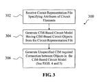
- FIG. 3 illustrates an exemplary method 300 for generating a CIM-based circuit model according to an exemplary embodiment of the present disclosure.
- the method 300 includes receiving a circuit representation file specifying attributes of circuit elements.
- the loader module 220 of FIG. 2 can receive a text based circuit representation file 210 specifying attributes of circuit elements.
- the method 300 includes generating a CIM-based circuit model having CIM-based circuit objects from the circuit representation file.
- loader module 220 of FIG. 2 can parse the circuit representation file 210 and create CIM conducting equipment objects as specified in a component section of the text based circuit representation file 210, can create and assign measurements as specified in the measurement section of the circuit representation file 210, and can connect equipment as specified in the connectivity section of the circuit representation file 210.
- the CIM based objects created from the circuit representation file 210 can be provided to model the model generator module 240.
- An application program interface in the model generator 240 can take string arguments, and use Java reflection to generate the CIM objects (conducting equipment objects, measurement objects, container objects, etc.) as required.
- the method 300 generates an unspecified CIM required connection between objects in the CIM-based circuit model.
- CIM models requires objects to have terminals, which must be connected to conductivity nodes, which must be connected by line segments.
- the method 300 automatically generates an unspecified CIM required connection, such as terminal object, conductivity node object, or line segment object, between objects in the CIM-based circuit model. This allows for simpler circuit specifications and increases efficiency.
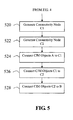
- FIGS. 4 and 5 illustrate an exemplary method 500 for generating an unspecified CIM required connection between objects according to an exemplary embodiment of the present disclosure.
- the method 500 will be discussed with reference to connecting two CIM objects A and B.
- terminal objects are automatically generated and associated with CIM objects A and B.
- the method 500 determines if one of the objects A or B is a line segment and if the other object is a connectivity node. If this condition is satisfied, objects A and B are connected in the CIM model as illustrated at 506. If this condition is not satisfied, the method 500 proceeds to 508.
- the method 500 determines if both objects A and B are connectivity nodes. If this condition is satisfied, the method 500 generates a line segment object L as shown at 510. At 512, the method connects object A to line segment object L and connects line segment object L to object B. If the condition is not satisfied, the method 500 proceeds to 514.
- the method determines whether A or B is a line segment. If this condition is satisfied, the method 500 generates a connectivity node C as shown at 516. At 518, the method 500 connects object A to connectivity node C and connects connectivity node C to object B. If the condition is not satisfied, the method 500 proceeds to 520 illustrated in FIG. 7.
- the method 500 generates connectivity node C1.
- the method generates connectivity node C2.
- the method 500 connects CIM object A to connectivity node C1.
- the method 500 connects connectivity node C1 to connectivity node C2.
- the method 500 connects connectivity node C2 to CIM object B.
- the method 500 ensures that all CIM objects are connected through connectivity nodes as required by the CIM model and any two connected CIM objects have a line segment between them. Accordingly, a tester can generate a CIM model including all CIM required connections even though such required connections are not specified in the circuit representation file.
- the comma-separated text based circuit representation file further facilitates the generation of CIM-based models by allowing a tester to provide simplified circuit definitions using a text editor or a spreadsheet tool.
- the present disclosure provides for fast availability of test circuit scenarios without the need for complex simulation framework or for extraction of data from a real model. This leads to reduced time in the development of test scenarios and reduction in development costs.
- the simplified circuit representation files provides testers the ability to report or communicate circuit scenarios in a visual way using a spreadsheet tool or text editor.
- the ability to develop circuit specification omitting unnecessary information required by the CIM-based model, such as CIM required connections, simplifies the creation of test case scenarios and verification of test results.
Landscapes
- Engineering & Computer Science (AREA)
- Physics & Mathematics (AREA)
- Theoretical Computer Science (AREA)
- Computer Hardware Design (AREA)
- Evolutionary Computation (AREA)
- Geometry (AREA)
- General Engineering & Computer Science (AREA)
- General Physics & Mathematics (AREA)
- Computer Networks & Wireless Communication (AREA)
- Design And Manufacture Of Integrated Circuits (AREA)
- Test And Diagnosis Of Digital Computers (AREA)
Abstract
Description
- The present disclosure relates generally to a common information model (CIM) based circuit model generator and more particularly to a CIM-based circuit model generator that generates valid CIM-based circuit models from simplified circuit definitions.
- Power system circuit models are typically developed for use by power system software to test various parameters and scenarios of a power system. The standard model known as the common information model (CIM) provides an open standard that defines how many typical objects used in power systems, such as transformers, buses, breakers, and other suitable objects, are represented in a power system circuit model. CIM-based circuit models can be used across multiple different power system testing platforms and can facilitate the exchange of circuit models and circuit data between multiple entities.
- Constructing CIM-based circuit models to test specific scenarios can be difficult and time consuming. For instance, the generation of a CIM-based circuit model can require the creation and manipulation of extensible markup language (XML) files. In addition, the generation of a CIM-based circuit model can require that all CIM objects be specified. For instance, a CIM-based model connection between one or more circuit objects requires specification of details such as terminals, connectivity nodes, line segments, and other CIM objects. As a result, the time necessary to generate CIM-based circuit models can lead to decreased productivity and delay in testing of power system scenarios.
- Thus, a system and method for generating CIM-based circuit models from simplified circuit definitions would be welcome in the art. A system and method that would provide for the automatic generation of objects required by the CIM model that are not essential for the particular testing purposes of an individual circuit, such as terminals, line segments, connectivity nodes, and other objects, would be particularly useful.
- Aspects and advantages of the invention will be set forth in part in the following description, or may be obvious from the description, or may be learned through practice of the invention.
- The present invention is directed to a method for generating a common information model (CIM) based circuit model. The method includes receiving a circuit representation file specifying attributes of one or more circuit elements. The method further includes generating with a computing device a CIM-based circuit model from the circuit representation file. The CIM-based circuit model includes a first CIM-based circuit object and a second CIM-based circuit object. The first and second CIM-based circuit objects are generated based at least in part on attributes specified in the circuit representation file. The method further includes generating with the computing device an unspecified CIM required connection in the CIM-based circuit model between the first CIM-based circuit object and the second CIM-based circuit object. The circuit representation file does not specify at least one attribute of the CIM required connection.
- The invention also resides in a computer program comprising computer program code adapted to perform the steps of the above method when run on a computer.
- The present invention is also directed to a computer-based system for generating a common information model (CIM) based circuit model. The system includes at least one processing device and at least one memory including the computer program described above embodied on a computer readable medium.
- Variations and modifications can be made to these exemplary embodiments of the present disclosure.
- These and other features, aspects and advantages of the present invention will become better understood with reference to the following description and appended claims. The accompanying drawings, which are incorporated in and constitute a part of this specification, illustrate embodiments of the invention and, together with the description, serve to explain the principles of the invention.
- Embodiments of the present invention will now be described, by way of example only, with reference to the accompanying drawings in which:
-
FIG. 1 illustrates a block diagram of an exemplary computing device that can be used to implement methods and systems according to exemplary embodiments of the present disclosure; -
FIG. 2 illustrates a block diagram of an exemplary system according to an exemplary embodiment of the present disclosure; -
FIG. 3 illustrates a flow chart of an exemplary method according to an exemplary embodiment of the present disclosure; and -
FIGS. 4 and5 illustrate a flow chart of an exemplary method for generating an unspecified CIM required connection according to an exemplary embodiment of the present disclosure. - Reference now will be made in detail to embodiments of the invention, one or more examples of which are illustrated in the drawings. Each example is provided by way of explanation of the invention, not limitation of the invention. In fact, it will be apparent to those skilled in the art that various modifications and variations can be made in the present invention without departing from the scope or spirit of the invention. For instance, features illustrated or described as part of one embodiment can be used with another embodiment to yield a still further embodiment. Thus, it is intended that the present invention covers such modifications and variations as come within the scope of the appended claims and their equivalents.
- Generally, the present disclosure is directed to systems and methods for generating common information model (CIM) based models of power systems to be used as a testing framework for power system software applications. Valid CIM-based circuit models can be constructed from simplified circuit definitions. In a particular implementation, CIM objects required by the CIM model that are not essential for the testing purposes of an individual circuit, such as terminals, line segments, connectivity nodes, and other CIM objects, are generated automatically and are not required in the circuit specifications.
- A loader module can be used to read simplified circuit definitions. For instance, in one implementation, a loader module reads circuit definitions written using a text-based, comma-separated value syntax. The loader module reads the definitions and creates, for instance through Java reflection, CIM objects, attributes, and measurements. A model generator module can be used to generate a CIM-based circuit model from the CIM objects. The model generator module allows the loader module to specify connections between two objects without specifying all the CIM required details. For instance, the CIM model requires that connections between two objects include terminals, which must connect to connectivity nodes, which must be connected via line segments. If not specified, the model generator module will construct the required CIM objects to connect the specified equipment.
- In this manner, the present subject matter allows testers to set-up CIM-based power system models using simplified circuit specifications. These specifications do not require terminals and do not require (but do allow) the tester to explicitly declare connectivity nodes or line segments. The text based, comma separated syntax used by the loader module can be generated by a variety of tools, including a text editor or spreadsheet tool, allowing for reduced time in the development and testing of power system scenarios. Fast availability of test circuit scenarios without the need for a complex simulation framework or for extraction of data from a real model allows for quick-start development of power system software and allows for reduction in development costs.
-
FIG. 1 illustrates an exemplary computer-basedsystem 100 that can be used to implement the systems and methods of the present disclosure. The computer basedsystem 100 can include one or more general-purpose or customized computing devices adapted in any suitable manner to provided desired functionality. Computer basedsystem 100 may be adapted to provide additional functionality complementary or unrelated to the present subject matter as well. As illustrated, computer-basedsystem 100 can include acomputing device 102 having amemory 104 and aprocessor 106.Memory 104 can be provided as a single or multiple portions of one or more varieties of computer-readable media, such as but not limited to any combination of volatile memory (e.g., random access memory (RAM, such as DRAM, SRAM, etc.) and nonvolatile memory (e.g., ROM, flash, hard drives, magnetic tapes, CD-ROM, DVD-ROM, etc.) or any other memory devices including diskettes, drives, other magnetic-based storage media, optical storage media, solid state storage media and others. -
Processor 106 can be a microprocessor or other suitable processing device configured to execute software instructions rendered in a computer-readable form stored inmemory 104. When software is used, any suitable programming, scripting, or other type of language or combinations of languages may be used to implement the teachings contained herein. In other embodiments, the methods disclosed herein may alternatively be implemented by hard-wired logic or other circuitry, including, but not limited to application-specific circuits. - As illustrated
computing device 102 can be coupled to input device(s) 108 and output device(s) 110. Exemplary input device(s) 108 can include but are not limited to a keyboard, touch-screen monitor, eye tracker, microphone, mouse and the like. Exemplary output device(s) 110 can include but are not limited to monitors, printers or other devices for visually depicting output data created in accordance with the disclosed technology. -
Computing device 102 can be connected toother computing devices 120 overnetwork 112.Network 112 can be comprise any number and/or combination of hard-wired, wireless, or other communication links. One of ordinary skill in the art will recognize that the inherent flexibility of computer-based systems allows for a great variety of possible configurations, combinations, and divisions of tasks and functionality between and among components. For instance, the processes discussed herein may be implemented usingsingle computing device 102 or across multiple computing devices, such ascomputing device 102 and computing device(s) 120 working in combination.Computing device 102 can also be coupled topower system 130 overnetwork 112. Computer basedsystem 100 can receive information and data from theactual power system 110 for use by power system software stored inmemory 104 ofcomputing device 102. -
FIG. 2 illustrates an exemplary system 200 for generating a CIM-based model according to an exemplary embodiment of the present disclosure. As illustrated, system 200 includes atext editor 204 or aspreadsheet tool 202, aloader module 220, amodel generator module 240, and anapplication program interface 250.Text editor 202,spreadsheet tool 204,loader module 220,model generator module 240, andapplication program interface 250 can be software implemented modules executed on one or more computing devices of a computer-based system. -
Spreadsheet tool 202 ortext editor 204 can be used to generate a simplifiedcircuit representation file 210. Simplifiedcircuit representation file 210 specifies attributes of one or more circuit elements to be modeled in a CIM-based power system circuit model. - In one particular implementation of the present disclosure, the simplified
circuit representation file 210 can be written in a comma-separated text based syntax. The comma-separated text basedcircuit representation file 210 simplifies the writing of an electric circuit specification by using standard text files that can be created and edited usingspreadsheet tool 202 andtext editor 204. Parsing of the text file is simplified by using the comma-separated values syntax. - The text based simplified
circuit representation file 210 can include a number of sections, with each section being separated by one or more comment lines. In a particular embodiment, the text based simplifiedcircuit representation file 210 includes a component section, a connectivity section, and a measurements section. The component section of the text based simplifiedcircuit representation file 210 defines the circuit conducting equipment objects of a particular CIM class (i.e. transformer, capacitor, substation, transmission line, etc.). The attributes, such as the master resource ID (MRID) and CIM class of the object can be specified in the component section of thecircuit representation file 210. The component section can define one or more objects of the same CIM class. - The connectivity section defines how the conducting equipment objects are connected in the circuit. There can be multiple connectivity sections in the same
circuit representation file 210. Each line in the connectivity section can include a list of component MRIDs and can specify the connections between the components in the list. - The way the components are specified in a line of the connectivity section is determined by the first element in the list. For example, if the first element in the line is the MRID of a connectivity node, then all of the subsequent elements in the list are connected to that connectivity node. If the first element in the line is the MRID of a transformer, then all the subsequent elements in the list must be transformer windings within the transformer. Otherwise, all the elements in the list are daisy-chained in the order in which they are listed.
- The measurement section of the text based simplified
circuit representation file 210 defines conducting equipment measurements. There can be multiple measurement sections. The first element in a line can be the MRID of the conducting equipment on which the measurement is set. The second element in the last can be the MRID of conducting equipment that is connected to the first conducting equipment, as specified in the connectivity section. This information can be used to determine the terminal in the conducting equipment on which to set the measurement. The third and fourth elements in the list can be the CIM measurement type and value. -
Loader module 220 parses thecircuit representation file 210 to generate one or more CIM-based objects as specified in the simplifiedcircuit representation file 210. While asingle loader module 220 is illustrated inFIG. 2 ,multiple loader modules 220 can be used as desired. Eachloader module 220 can be configured to read a specific type of simplified circuit representation file. For instance, oneloader module 220 can be used to load a comma-separated text based circuit representation file. Anotherloader module 220 can be used to load a graphic-based circuit representation file. - The
model generator module 240 includes an application program interface to be used byloader module 220 for building the CIM-based power system model. The application program interface of themodel generator module 240 creates CIM based objects as specified in the circuit representation file Themodel generator module 240 further generates unspecified CIM required connections in the CIM based model as will be discussed in detail below. - The
model generator module 240 provides the CIM based model toapplication program interface 250 for use bypower system software 260. Theapplication program interface 250 can be the same interface layer thatpower system software 260 uses to retrieve information from anactual power system 270. This allows the model generator module to impersonate a real power system and to supply circuit information to thepower systems software 260. -
FIG. 3 illustrates anexemplary method 300 for generating a CIM-based circuit model according to an exemplary embodiment of the present disclosure. At 302, themethod 300 includes receiving a circuit representation file specifying attributes of circuit elements. For instance, theloader module 220 ofFIG. 2 can receive a text basedcircuit representation file 210 specifying attributes of circuit elements. - Referring back to
FIG. 3 at 304, themethod 300 includes generating a CIM-based circuit model having CIM-based circuit objects from the circuit representation file. For instance, in a particular embodiment,loader module 220 ofFIG. 2 can parse thecircuit representation file 210 and create CIM conducting equipment objects as specified in a component section of the text basedcircuit representation file 210, can create and assign measurements as specified in the measurement section of thecircuit representation file 210, and can connect equipment as specified in the connectivity section of thecircuit representation file 210. - The CIM based objects created from the
circuit representation file 210 can be provided to model themodel generator module 240. An application program interface in themodel generator 240 can take string arguments, and use Java reflection to generate the CIM objects (conducting equipment objects, measurement objects, container objects, etc.) as required. - Referring back to
FIG. 3 , themethod 300 generates an unspecified CIM required connection between objects in the CIM-based circuit model. CIM models requires objects to have terminals, which must be connected to conductivity nodes, which must be connected by line segments. Themethod 300 automatically generates an unspecified CIM required connection, such as terminal object, conductivity node object, or line segment object, between objects in the CIM-based circuit model. This allows for simpler circuit specifications and increases efficiency. -
FIGS. 4 and5 illustrate anexemplary method 500 for generating an unspecified CIM required connection between objects according to an exemplary embodiment of the present disclosure. For illustrative purposes, themethod 500 will be discussed with reference to connecting two CIM objects A and B. Those of ordinary skill in the art, using the disclosures provided herein, should understand that multiple objects and multiple connections can be generated in the CIM-based model without deviating from the scope of the present disclosure. - At 502, terminal objects are automatically generated and associated with CIM objects A and B. At 504, the
method 500 determines if one of the objects A or B is a line segment and if the other object is a connectivity node. If this condition is satisfied, objects A and B are connected in the CIM model as illustrated at 506. If this condition is not satisfied, themethod 500 proceeds to 508. - At 508, the
method 500 determines if both objects A and B are connectivity nodes. If this condition is satisfied, themethod 500 generates a line segment object L as shown at 510. At 512, the method connects object A to line segment object L and connects line segment object L to object B. If the condition is not satisfied, themethod 500 proceeds to 514. - At 514, the method determines whether A or B is a line segment. If this condition is satisfied, the
method 500 generates a connectivity node C as shown at 516. At 518, themethod 500 connects object A to connectivity node C and connects connectivity node C to object B. If the condition is not satisfied, themethod 500 proceeds to 520 illustrated in FIG. 7. - At 520, the
method 500 generates connectivity node C1. At 522, the method generates connectivity node C2. At 524, themethod 500 connects CIM object A to connectivity node C1. At 526, themethod 500 connects connectivity node C1 to connectivity node C2. Finally, at 528, themethod 500 connects connectivity node C2 to CIM object B. - The
method 500 ensures that all CIM objects are connected through connectivity nodes as required by the CIM model and any two connected CIM objects have a line segment between them. Accordingly, a tester can generate a CIM model including all CIM required connections even though such required connections are not specified in the circuit representation file. The comma-separated text based circuit representation file further facilitates the generation of CIM-based models by allowing a tester to provide simplified circuit definitions using a text editor or a spreadsheet tool. - The present disclosure provides for fast availability of test circuit scenarios without the need for complex simulation framework or for extraction of data from a real model. This leads to reduced time in the development of test scenarios and reduction in development costs. The simplified circuit representation files provides testers the ability to report or communicate circuit scenarios in a visual way using a spreadsheet tool or text editor. The ability to develop circuit specification omitting unnecessary information required by the CIM-based model, such as CIM required connections, simplifies the creation of test case scenarios and verification of test results.
- This written description uses examples to disclose the invention, including the best mode, and also to enable any person skilled in the art to practice the invention, including making and using any devices or systems and performing any incorporated methods. The patentable scope of the invention is defined by the claims, and may include other examples that occur to those skilled in the art. Such other examples are intended to be within the scope of the claims if they include structural elements that do not differ from the literal language of the claims, or if they include equivalent structural elements with insubstantial differences from the literal languages of the claims.
Claims (10)
- A method (300) for generating a common information model (CIM) based circuit model, comprising:receiving a circuit representation file (210) specifying attributes of one or more circuit elements;generating a CIM-based circuit model from the circuit representation file (210), the CIM-based circuit model comprising a first CIM-based circuit object and a second CIM-based circuit object, the first CIM-based circuit object and the second CIM-based circuit object being generated based at least in part on the attributes specified in the circuit representation file (210) (320); andgenerating an unspecified CIM required connection in the CIM-based circuit model between the first CIM-based circuit object and the second CIM-based circuit object (330);wherein the circuit representation file (210) does not specify at least one attribute for the unspecified CIM required connection.
- The method of claim 1, wherein the unspecified CIM required connection comprises at least one of a terminal object, connectivity node object, or a line segment object.
- The method of claim 1 or 2, wherein the circuit representation file (210) comprises a comma-separated text file.
- The method of claim 3, wherein the comma-separated text file comprises a component section, a connectivity section, and a measurement section, wherein the component section defines one or more circuit conducting equipment objects of a particular CIM class, the connectivity section defines how the conducting equipment objects are connected, and the measurement section defines conducting equipment measurements.
- The method of claim 3, wherein the comma-separated text file is received at a loader module, and further comprising:parsing the comma-separated text file with the loader module; andgenerating the CIM-based circuit model from the parsed text file.
- The method of any of claims 1 to 4, wherein generating with the computing device an unspecified CIM required connection in the CIM-based circuit model (330) comprises:generating at least one first terminal object for the first CIM-based circuit object (502);generating at least one second terminal object for the second CIM-based circuit object (502);identifying the CIM class associated with the first CIM-based circuit object and the CIM class associated with the second CIM-based circuit object (504, 508, 514); andgenerating a CIM required connection between the first terminal object and the second terminal object based at least in part on the CIM class of the first CIM-based circuit object and the CIM class of the second CIM-based circuit object (506, 510, 512,516,518,520,522,524,526,528).
- The method of any of claims 1 to 6, wherein the method (300) further comprises providing the CIM-based model to an application program interface (250) for retrieval by a power system software application (260).
- A computer program comprising computer program codes means adapted to perform all the steps of the method of any of claims 1 to 7, when run on a computer.
- The computer program of claim 8, embodied on a computer readable medium.
- A computer-based system (100) for generating a common information model (CIM) based circuit model, comprising:at least one processing device (106); andat least one memory (104) comprising the computer program of claim 9.
Applications Claiming Priority (1)
| Application Number | Priority Date | Filing Date | Title |
|---|---|---|---|
| US13/083,761 US20120259611A1 (en) | 2011-04-11 | 2011-04-11 | System and method for generation of cim-based power system circuit models |
Publications (2)
| Publication Number | Publication Date |
|---|---|
| EP2511841A2 true EP2511841A2 (en) | 2012-10-17 |
| EP2511841A3 EP2511841A3 (en) | 2015-03-04 |
Family
ID=46022037
Family Applications (1)
| Application Number | Title | Priority Date | Filing Date |
|---|---|---|---|
| EP12163130.3A Withdrawn EP2511841A3 (en) | 2011-04-11 | 2012-04-04 | System and method for generation of cim-based power system circuit models |
Country Status (4)
| Country | Link |
|---|---|
| US (1) | US20120259611A1 (en) |
| EP (1) | EP2511841A3 (en) |
| CN (1) | CN102750401A (en) |
| IN (1) | IN2012DE00914A (en) |
Cited By (1)
| Publication number | Priority date | Publication date | Assignee | Title |
|---|---|---|---|---|
| CN109557827A (en) * | 2017-09-25 | 2019-04-02 | 中国电力科学研究院 | A kind of generation of power grid logic control script and result emulation mode and system |
Families Citing this family (6)
| Publication number | Priority date | Publication date | Assignee | Title |
|---|---|---|---|---|
| US8706468B2 (en) * | 2011-09-20 | 2014-04-22 | General Electric Company | Method and program product for validation of circuit models for phase connectivity |
| JP6008695B2 (en) * | 2012-11-01 | 2016-10-19 | 株式会社日立製作所 | Power system facility data model conversion method, power system facility data model conversion device, and power system facility data model conversion program |
| CN103927385A (en) * | 2014-04-25 | 2014-07-16 | 国家电网公司 | Unifying method and device of data model |
| CN104392398B (en) * | 2014-12-09 | 2017-06-09 | 国家电网公司 | Power distribution automation CIM imports and exports function test system and its method |
| CN117112630B (en) * | 2023-09-15 | 2024-07-19 | 国网江苏省电力有限公司信息通信分公司 | Method, device, equipment and storage medium for generating topological structure of power grid data |
| CN117349493B (en) * | 2023-09-27 | 2024-07-26 | 广东电网有限责任公司 | Method and device for visual display of power system data based on cim model |
Family Cites Families (5)
| Publication number | Priority date | Publication date | Assignee | Title |
|---|---|---|---|---|
| US6516326B1 (en) * | 2000-10-30 | 2003-02-04 | Stone And Webster Consultants, Inc. | System and method for integrating electrical power grid and related data from various proprietary raw data formats into a single maintainable electrically connected database |
| EP1828925A1 (en) * | 2004-08-16 | 2007-09-05 | Abb Research Ltd. | Method and system for bi-directional data conversion between iec 61970 and iec 61850 |
| US7624116B2 (en) * | 2006-03-23 | 2009-11-24 | Dell Products L.P. | System and method for managing objects according to the common information model |
| CN101661527B (en) * | 2009-09-25 | 2012-09-26 | 江西九江供电公司 | Automatic switching system from geographical wiring diagram of distribution network to single line diagram |
| CN101873008B (en) * | 2010-07-02 | 2012-05-23 | 国电南瑞科技股份有限公司 | Method for converting SCD (substation configuration description) model into CIM (common information model) model of dispatching center |
-
2011
- 2011-04-11 US US13/083,761 patent/US20120259611A1/en not_active Abandoned
-
2012
- 2012-03-27 IN IN914DE2012 patent/IN2012DE00914A/en unknown
- 2012-04-04 EP EP12163130.3A patent/EP2511841A3/en not_active Withdrawn
- 2012-04-11 CN CN2012101149705A patent/CN102750401A/en active Pending
Non-Patent Citations (1)
| Title |
|---|
| None |
Cited By (2)
| Publication number | Priority date | Publication date | Assignee | Title |
|---|---|---|---|---|
| CN109557827A (en) * | 2017-09-25 | 2019-04-02 | 中国电力科学研究院 | A kind of generation of power grid logic control script and result emulation mode and system |
| CN109557827B (en) * | 2017-09-25 | 2021-10-01 | 中国电力科学研究院 | A method and system for generation and result simulation of power grid logic control script |
Also Published As
| Publication number | Publication date |
|---|---|
| US20120259611A1 (en) | 2012-10-11 |
| IN2012DE00914A (en) | 2015-09-11 |
| CN102750401A (en) | 2012-10-24 |
| EP2511841A3 (en) | 2015-03-04 |
Similar Documents
| Publication | Publication Date | Title |
|---|---|---|
| EP2511841A2 (en) | System and method for generation of cim-based power system circuit models | |
| US8689177B2 (en) | Integration environment generator | |
| US9838264B2 (en) | Method and digital tool for engineering software architectures of complex cyber-physical systems of different technical domains | |
| CN102592023A (en) | Register designing method and register designing device in integrated circuit designing process | |
| CN104932480A (en) | Automobile diagnostic system design method and apparatus | |
| CN108804322A (en) | Automated testing method, device, computer equipment and storage medium | |
| CN107729228A (en) | Interface test method, device, storage medium and processor | |
| CN117931666B (en) | System and method for testing core framework of software radio communication equipment | |
| CN113705143A (en) | Automatic simulation system and automatic simulation method | |
| CN113467782B (en) | Method, device and equipment for determining business process | |
| CN111399828B (en) | Model-driven logic device modeling method and terminal | |
| CN116680885A (en) | Complex device control software modeling and verification method based on SysML and Tango | |
| CN113704099A (en) | Test script generation method and equipment for spacecraft power system evaluation | |
| CN101976196B (en) | Quality of service oriented code automatic code generating method | |
| CN104765616B (en) | A kind of method and system for automatically generating I/O model | |
| CN111245633B (en) | Configuration file of micro-grid main equipment and operation method thereof | |
| CN107590044B (en) | Testing method, device and equipment for distributed storage cluster | |
| US20140324918A1 (en) | Database Generation System, Method For Generating A Database, Product Line Management System And Non-Transitory Data Carrier | |
| CN117892665B (en) | Modeling simulation method, device, medium and equipment based on circuit system level model | |
| CN116227402B (en) | Modeling method and device of analog circuit and electronic equipment | |
| CN112306622A (en) | VNF template construction method and device | |
| CN117891700A (en) | 61850 transformer substation spacer layer GOOSE data simulation method | |
| CN109522210A (en) | Interface testing parameters analysis method, device, electronic device and storage medium | |
| CN106815303A (en) | A kind of crumbs navigation implementation method and system based on XML configurations and label | |
| CN109492239A (en) | A kind of device for realizing simulation waveform data Real-time segmentation |
Legal Events
| Date | Code | Title | Description |
|---|---|---|---|
| PUAI | Public reference made under article 153(3) epc to a published international application that has entered the european phase |
Free format text: ORIGINAL CODE: 0009012 |
|
| AK | Designated contracting states |
Kind code of ref document: A2 Designated state(s): AL AT BE BG CH CY CZ DE DK EE ES FI FR GB GR HR HU IE IS IT LI LT LU LV MC MK MT NL NO PL PT RO RS SE SI SK SM TR |
|
| AX | Request for extension of the european patent |
Extension state: BA ME |
|
| PUAL | Search report despatched |
Free format text: ORIGINAL CODE: 0009013 |
|
| AK | Designated contracting states |
Kind code of ref document: A3 Designated state(s): AL AT BE BG CH CY CZ DE DK EE ES FI FR GB GR HR HU IE IS IT LI LT LU LV MC MK MT NL NO PL PT RO RS SE SI SK SM TR |
|
| AX | Request for extension of the european patent |
Extension state: BA ME |
|
| RIC1 | Information provided on ipc code assigned before grant |
Ipc: H02J 3/00 20060101ALI20150127BHEP Ipc: G06F 17/50 20060101AFI20150127BHEP |
|
| STAA | Information on the status of an ep patent application or granted ep patent |
Free format text: STATUS: THE APPLICATION IS DEEMED TO BE WITHDRAWN |
|
| 18D | Application deemed to be withdrawn |
Effective date: 20150905 |