EP2511796A2 - Input apparatus comprising a touch sensitive input device and a rotatable input device - Google Patents
Input apparatus comprising a touch sensitive input device and a rotatable input device Download PDFInfo
- Publication number
- EP2511796A2 EP2511796A2 EP12159725A EP12159725A EP2511796A2 EP 2511796 A2 EP2511796 A2 EP 2511796A2 EP 12159725 A EP12159725 A EP 12159725A EP 12159725 A EP12159725 A EP 12159725A EP 2511796 A2 EP2511796 A2 EP 2511796A2
- Authority
- EP
- European Patent Office
- Prior art keywords
- support body
- input device
- shaft
- movement
- operation knob
- Prior art date
- Legal status (The legal status is an assumption and is not a legal conclusion. Google has not performed a legal analysis and makes no representation as to the accuracy of the status listed.)
- Granted
Links
Images



Classifications
-
- G—PHYSICS
- G06—COMPUTING OR CALCULATING; COUNTING
- G06F—ELECTRIC DIGITAL DATA PROCESSING
- G06F3/00—Input arrangements for transferring data to be processed into a form capable of being handled by the computer; Output arrangements for transferring data from processing unit to output unit, e.g. interface arrangements
- G06F3/01—Input arrangements or combined input and output arrangements for interaction between user and computer
- G06F3/03—Arrangements for converting the position or the displacement of a member into a coded form
- G06F3/033—Pointing devices displaced or positioned by the user, e.g. mice, trackballs, pens or joysticks; Accessories therefor
- G06F3/0354—Pointing devices displaced or positioned by the user, e.g. mice, trackballs, pens or joysticks; Accessories therefor with detection of two-dimensional [2D] relative movements between the device, or an operating part thereof, and a plane or surface, e.g. 2D mice, trackballs, pens or pucks
- G06F3/03547—Touch pads, in which fingers can move on a surface
-
- B—PERFORMING OPERATIONS; TRANSPORTING
- B60—VEHICLES IN GENERAL
- B60K—ARRANGEMENT OR MOUNTING OF PROPULSION UNITS OR OF TRANSMISSIONS IN VEHICLES; ARRANGEMENT OR MOUNTING OF PLURAL DIVERSE PRIME-MOVERS IN VEHICLES; AUXILIARY DRIVES FOR VEHICLES; INSTRUMENTATION OR DASHBOARDS FOR VEHICLES; ARRANGEMENTS IN CONNECTION WITH COOLING, AIR INTAKE, GAS EXHAUST OR FUEL SUPPLY OF PROPULSION UNITS IN VEHICLES
- B60K35/00—Instruments specially adapted for vehicles; Arrangement of instruments in or on vehicles
- B60K35/10—Input arrangements, i.e. from user to vehicle, associated with vehicle functions or specially adapted therefor
-
- G—PHYSICS
- G05—CONTROLLING; REGULATING
- G05G—CONTROL DEVICES OR SYSTEMS INSOFAR AS CHARACTERISED BY MECHANICAL FEATURES ONLY
- G05G1/00—Controlling members, e.g. knobs or handles; Assemblies or arrangements thereof; Indicating position of controlling members
- G05G1/02—Controlling members for hand actuation by linear movement, e.g. push buttons
-
- G—PHYSICS
- G05—CONTROLLING; REGULATING
- G05G—CONTROL DEVICES OR SYSTEMS INSOFAR AS CHARACTERISED BY MECHANICAL FEATURES ONLY
- G05G1/00—Controlling members, e.g. knobs or handles; Assemblies or arrangements thereof; Indicating position of controlling members
- G05G1/08—Controlling members for hand actuation by rotary movement, e.g. hand wheels
-
- G—PHYSICS
- G06—COMPUTING OR CALCULATING; COUNTING
- G06F—ELECTRIC DIGITAL DATA PROCESSING
- G06F3/00—Input arrangements for transferring data to be processed into a form capable of being handled by the computer; Output arrangements for transferring data from processing unit to output unit, e.g. interface arrangements
- G06F3/01—Input arrangements or combined input and output arrangements for interaction between user and computer
- G06F3/03—Arrangements for converting the position or the displacement of a member into a coded form
- G06F3/033—Pointing devices displaced or positioned by the user, e.g. mice, trackballs, pens or joysticks; Accessories therefor
- G06F3/0362—Pointing devices displaced or positioned by the user, e.g. mice, trackballs, pens or joysticks; Accessories therefor with detection of one-dimensional [1D] translations or rotations of an operating part of the device, e.g. scroll wheels, sliders, knobs, rollers or belts
-
- H—ELECTRICITY
- H01—ELECTRIC ELEMENTS
- H01H—ELECTRIC SWITCHES; RELAYS; SELECTORS; EMERGENCY PROTECTIVE DEVICES
- H01H19/00—Switches operated by an operating part which is rotatable about a longitudinal axis thereof and which is acted upon directly by a solid body external to the switch, e.g. by a hand
- H01H19/02—Details
- H01H19/10—Movable parts; Contacts mounted thereon
- H01H19/11—Movable parts; Contacts mounted thereon with indexing means
-
- H—ELECTRICITY
- H01—ELECTRIC ELEMENTS
- H01H—ELECTRIC SWITCHES; RELAYS; SELECTORS; EMERGENCY PROTECTIVE DEVICES
- H01H25/00—Switches with compound movement of handle or other operating part
- H01H25/06—Operating part movable both angularly and rectilinearly, the rectilinear movement being along the axis of angular movement
-
- H—ELECTRICITY
- H01—ELECTRIC ELEMENTS
- H01H—ELECTRIC SWITCHES; RELAYS; SELECTORS; EMERGENCY PROTECTIVE DEVICES
- H01H9/00—Details of switching devices, not covered by groups H01H1/00 - H01H7/00
- H01H9/18—Distinguishing marks on switches, e.g. for indicating switch location in the dark; Adaptation of switches to receive distinguishing marks
- H01H9/182—Illumination of the symbols or distinguishing marks
-
- H—ELECTRICITY
- H03—ELECTRONIC CIRCUITRY
- H03K—PULSE TECHNIQUE
- H03K17/00—Electronic switching or gating, i.e. not by contact-making and –breaking
- H03K17/94—Electronic switching or gating, i.e. not by contact-making and –breaking characterised by the way in which the control signals are generated
- H03K17/96—Touch switches
- H03K17/962—Capacitive touch switches
-
- H—ELECTRICITY
- H03—ELECTRONIC CIRCUITRY
- H03K—PULSE TECHNIQUE
- H03K17/00—Electronic switching or gating, i.e. not by contact-making and –breaking
- H03K17/94—Electronic switching or gating, i.e. not by contact-making and –breaking characterised by the way in which the control signals are generated
- H03K17/965—Switches controlled by moving an element forming part of the switch
- H03K17/968—Switches controlled by moving an element forming part of the switch using opto-electronic devices
-
- B—PERFORMING OPERATIONS; TRANSPORTING
- B60—VEHICLES IN GENERAL
- B60K—ARRANGEMENT OR MOUNTING OF PROPULSION UNITS OR OF TRANSMISSIONS IN VEHICLES; ARRANGEMENT OR MOUNTING OF PLURAL DIVERSE PRIME-MOVERS IN VEHICLES; AUXILIARY DRIVES FOR VEHICLES; INSTRUMENTATION OR DASHBOARDS FOR VEHICLES; ARRANGEMENTS IN CONNECTION WITH COOLING, AIR INTAKE, GAS EXHAUST OR FUEL SUPPLY OF PROPULSION UNITS IN VEHICLES
- B60K2360/00—Indexing scheme associated with groups B60K35/00 or B60K37/00 relating to details of instruments or dashboards
- B60K2360/126—Rotatable input devices for instruments
-
- B—PERFORMING OPERATIONS; TRANSPORTING
- B60—VEHICLES IN GENERAL
- B60K—ARRANGEMENT OR MOUNTING OF PROPULSION UNITS OR OF TRANSMISSIONS IN VEHICLES; ARRANGEMENT OR MOUNTING OF PLURAL DIVERSE PRIME-MOVERS IN VEHICLES; AUXILIARY DRIVES FOR VEHICLES; INSTRUMENTATION OR DASHBOARDS FOR VEHICLES; ARRANGEMENTS IN CONNECTION WITH COOLING, AIR INTAKE, GAS EXHAUST OR FUEL SUPPLY OF PROPULSION UNITS IN VEHICLES
- B60K2360/00—Indexing scheme associated with groups B60K35/00 or B60K37/00 relating to details of instruments or dashboards
- B60K2360/141—Activation of instrument input devices by approaching fingers or pens
-
- B—PERFORMING OPERATIONS; TRANSPORTING
- B60—VEHICLES IN GENERAL
- B60K—ARRANGEMENT OR MOUNTING OF PROPULSION UNITS OR OF TRANSMISSIONS IN VEHICLES; ARRANGEMENT OR MOUNTING OF PLURAL DIVERSE PRIME-MOVERS IN VEHICLES; AUXILIARY DRIVES FOR VEHICLES; INSTRUMENTATION OR DASHBOARDS FOR VEHICLES; ARRANGEMENTS IN CONNECTION WITH COOLING, AIR INTAKE, GAS EXHAUST OR FUEL SUPPLY OF PROPULSION UNITS IN VEHICLES
- B60K2360/00—Indexing scheme associated with groups B60K35/00 or B60K37/00 relating to details of instruments or dashboards
- B60K2360/143—Touch sensitive instrument input devices
-
- H—ELECTRICITY
- H01—ELECTRIC ELEMENTS
- H01H—ELECTRIC SWITCHES; RELAYS; SELECTORS; EMERGENCY PROTECTIVE DEVICES
- H01H19/00—Switches operated by an operating part which is rotatable about a longitudinal axis thereof and which is acted upon directly by a solid body external to the switch, e.g. by a hand
- H01H19/02—Details
- H01H19/025—Light-emitting indicators
-
- H—ELECTRICITY
- H01—ELECTRIC ELEMENTS
- H01H—ELECTRIC SWITCHES; RELAYS; SELECTORS; EMERGENCY PROTECTIVE DEVICES
- H01H3/00—Mechanisms for operating contacts
- H01H3/02—Operating parts, i.e. for operating driving mechanism by a mechanical force external to the switch
- H01H2003/0293—Operating parts, i.e. for operating driving mechanism by a mechanical force external to the switch with an integrated touch switch
-
- H—ELECTRICITY
- H03—ELECTRONIC CIRCUITRY
- H03K—PULSE TECHNIQUE
- H03K2217/00—Indexing scheme related to electronic switching or gating, i.e. not by contact-making or -breaking covered by H03K17/00
- H03K2217/94—Indexing scheme related to electronic switching or gating, i.e. not by contact-making or -breaking covered by H03K17/00 characterised by the way in which the control signal is generated
- H03K2217/94057—Rotary switches
- H03K2217/94063—Rotary switches with optical detection
-
- H—ELECTRICITY
- H03—ELECTRONIC CIRCUITRY
- H03K—PULSE TECHNIQUE
- H03K2217/00—Indexing scheme related to electronic switching or gating, i.e. not by contact-making or -breaking covered by H03K17/00
- H03K2217/94—Indexing scheme related to electronic switching or gating, i.e. not by contact-making or -breaking covered by H03K17/00 characterised by the way in which the control signal is generated
- H03K2217/96—Touch switches
- H03K2217/9607—Capacitive touch switches
- H03K2217/960755—Constructional details of capacitive touch and proximity switches
Definitions
- the present invention relates to an input device having at least an operation body on which a rotation operation is capable of being performed, and specifically relates to an input device including a touch pad which is provided on a back surface side of an operation body and detects approach or contact of a finger.
- an input device which includes an operation body freely rotated and reciprocated relative to a base member, in which the operation body includes an operation knob formed in a cylindrical shape having a top surface portion, in which a touch pad for detecting approach or contact of a finger with respect to the top surface portion is provided on a back surface side of the top surface portion constituting the operation knob, and in which an input is made by approach or contact of a finger with respect to the top surface portion of the operation knob as well as a rotation operation and a pressing operation of the operation body.
- Such an input device is, for example, an input device disclosed in International Publication No. 2010/000281 .
- a support body which supports the touch pad.
- a support body is provided within a base member, a wire to the touch pad is located therein, and a detection portion for detecting a rotation operation and a pressing operation of an operation body is located on a peripheral portion of the support body.
- a space for locating the detection portion needs to be ensured outward in the radial direction of the input device, and this inhibits size reduction of the input device.
- the present invention is made in view of the problem described above and provides an input device which can be reduced in size in a radial direction thereof while including a touch pad and an operation body on which a rotation operation and a pressing operation are capable of being performed.
- the present invention provides an input device including: a base member including a hollow support body; and an operation body supported so as to freely rotate relative to the hollow support body and freely reciprocate along a direction of a rotational axis.
- the operation body includes an operation knob formed in a cylindrical shape and having a top surface portion and a plate-shaped touch pad provided on a back side of the top surface portion for detecting approach or contact of a finger with respect to the top surface portion.
- the base member has a space formed so as to extend from an inside of the base member to an inside of the hollow support body.
- the operation knob has a shaft provided vertically so as to extend from a back surface of the top surface portion.
- the touch pad has a through hole through which the shaft is inserted into the space.
- a rotation detection portion for detecting a rotating movement of the operation body and a pressing detection portion for detecting a reciprocating movement of the operation body are provided.
- the shaft is linked to a rotating movement portion which makes a rotation detection movement for the rotation detection portion with a rotating movement of the operation body, and to a pressing movement portion which makes a pressing detection movement for the pressing detection portion with a reciprocating movement of the operation body.
- an interlocking shaft is located in the space and connected to the shaft, and the rotating movement portion and the pressing movement portion are provided in the interlocking shaft.
- the shaft and the interlocking shaft are connected to each other through a cam portion having a plurality of cam surfaces formed along a peripheral surface thereof, and an elastic portion is provided in the hollow support body and engages with and disengages from the cam surfaces with a rotating movement of the operation body.
- the rotation detection portion and the pressing detection portion are located so as to face the space.
- the operation body has a support body which rotationally supports the operation knob, and the support body is supported by the hollow support body so as to reciprocate along a direction of a rotational axis of the operation knob.
- the support body and the operation knob are allowed to freely rotate along a peripheral surface of the support body by a bearing portion which includes an inner ring portion fixed to the support body and an outer ring portion fixed to the operation knob, and the inner ring portion and the outer ring portion freely rotate relative to each other.
- the operation knob has the shaft provided vertically so as to extend from the back surface of the top surface portion, the touch pad has the through hole through which the shaft is inserted into the space, and in the space, the shaft is linked to the rotating movement portion which makes a rotation detection movement for the rotation detection portion with a rotating movement of the operation body, and to the pressing movement portion which makes a pressing detection movement for the pressing detection portion with a reciprocating movement of the operation body.
- parts required to detect a rotation operation and a pressing operation of the operation body can be located in a space below the capacitance type touch pad provided on the back side of the top surface portion of the operation knob, namely, in the space which extends from the inside of the base member to the inside of the support body, and it is unnecessary to locate the parts widely in the radial direction.
- size reduction in the radial direction can be achieved.
- the interlocking shaft is located in the space and connected to the shaft, and the rotating movement portion and the pressing movement portion are provided in the interlocking shaft.
- the shaft and the interlocking shaft can be connected to each other with a simple structure, and the shaft can be linked to the rotating movement portion and the pressing movement portion with a simple configuration.
- the shaft and the interlocking shaft are connected to each other through the cam portion having the plurality of cam surfaces formed along the peripheral surface thereof, and the elastic portion is provided in the hollow support body and engages with and disengages from the cam surfaces with a rotating movement of the operation body.
- a click mechanism can be made compact and provide a smooth click feel, and a connection member between the shaft and the interlocking shaft is configured to serve as the click mechanism.
- the entire device can be further reduced in size.
- the rotation detection portion and the pressing detection portion are located so as to face the space from the outside of the space.
- a space for locating parts can be effectively used, and size reduction can be achieved.
- the operation body includes the support body which rotationally supports the operation knob, and the support body is supported by the hollow support body so as to reciprocate along the direction of the rotational axis of the operation knob.
- the click mechanism can be provided at a position different from a rotation support portion for the operation knob.
- the support body and the operation knob are allowed to freely rotate along the peripheral surface of the support body by the bearing portion which includes the inner ring portion fixed to the support body and the outer ring portion fixed to the operation knob, and the inner ring portion and the outer ring portion freely rotate relative to each other.
- the bearing portion which includes the inner ring portion fixed to the support body and the outer ring portion fixed to the operation knob, and the inner ring portion and the outer ring portion freely rotate relative to each other.
- FIG. 1 shows a front view of a center console 1 including an input device 2 according to the embodiment.
- the center console 1 is located between a driver seat and a passenger seat of a vehicle.
- the input device 2 and switches 3 through which various inputs are made are located on a surface of the center console 1.
- the input device 2 of the embodiment includes: an operation knob 20 which has a cylindrical shape with a bottom, is exposed in the vehicle interior, can be rotated along a circumferential direction thereof, and can be pressed in a direction perpendicular to the surface of the center console 1; and a plate-shaped capacitance type touch pad 7 (hereinafter, referred to merely as touch pad; Fig. 4 ) which is provided on the back side of the top surface portion 20c and can detect approach or contact of a finger with respect to a surface of a top surface portion 20c of the operation knob 20.
- an operation knob 20 which has a cylindrical shape with a bottom, is exposed in the vehicle interior, can be rotated along a circumferential direction thereof, and can be pressed in a direction perpendicular to the surface of the center console 1
- a plate-shaped capacitance type touch pad 7 hereinafter, referred to merely as touch pad; Fig. 4
- Fig. 2 shows an enlarged cross-sectional view taken along the II-II line in Fig. 1 around the input device 2
- Fig. 3 shows an enlarged cross-sectional view taken along the III-III line in Fig. 1 around the input device 2.
- the input device 2 of the embodiment is configured such that an operation body 6 is mounted on a hollow support body 11 provided vertically so as to extend upright from a hollow base member 5 placed on a base plate 10, such that the operation body 6 freely rotates and freely reciprocates in the vertical direction in Fig. 2 (in the direction of the rotational axis) as described above.
- a rotation detection portion 8 In a region of the base plate 10 which faces the inner space of the base member 5, a rotation detection portion 8 ( Fig.
- the rotation detection portion 8 is configured as a photointerrupter which includes a light-receiving element and a light-emitting element which face each other across a lower end side (a side on which a slit 33a is formed) of a cylindrical code plate 33 mounted on an interlocking shaft 32, and the pressing detection portion 9 is configured as a pressing switch.
- the operation body 6 includes the operation knob 20 formed in a cylindrical shape having the top surface portion 20c, and a hollow cylindrical support body 21 which rotationally holds the operation knob 20 through a bearing portion 22. Meanwhile, the support body 21 freely reciprocates relative to the hollow support body 11 (the base member 5) together with the operation knob 20 in the vertical direction in the drawing (in the direction of the rotational axis). Thus, since the operation knob 20 freely rotates relative to the support body 21 only along the circumferential direction thereof, the operation knob 20 freely rotates relative to the base member 5.
- Fig. 6 shows a schematic cross-sectional view of a relevant portion along the VI-VI line in Fig. 2 .
- the support body 21 has, in an inner peripheral surface (inner wall) thereof, a plurality of grooves (recesses) 21a extending in the vertical direction
- the hollow support body 11 provided vertically on the base member 5 has, in an outer peripheral surface (outer wall) thereof, a guide rail (projection) 11a which engages with each groove 21a so as to be guided by the groove 21a. Due to this configuration, the support body 21 is assuredly and stably supported so as to freely reciprocate relative to the hollow support body 11 (the base member 5) together with the operation knob 20 in the vertical direction in the drawing.
- the grooves 21a may be formed in the outer wall of the hollow support body 11 and the guide rails 11a may be formed in the inner wall of the support body 21.
- the hollow support body 11 serves as an operation body support portion, namely, serves to support the operation body 6 such that the operation body 6 freely reciprocates only in the vertical direction, and thus may be formed in a hollow cylindrical shape.
- the support body 21 may have a space having a polygonal transverse cross section, and the hollow support body 11 may have an outer shape corresponding to the space shape of the support body 21.
- the hollow support body 11 is formed in such a position that the operation body 6 freely rotates and freely reciprocates in the vertical direction.
- the hollow support body 11 is formed so as to have a step in a peripheral surface thereof, and the support body 21 is provided outside the hollow support body 11 so as to cover its peripheral surface.
- the support body 21 has a hollow cylindrical shape, and thus has the space 21f formed therein.
- an accommodation portion 12 is formed outside a base end portion of the hollow support body 11 on the base member 5 so as to have a recess shape and so as to extend in the circumferential direction over 180 degrees.
- a lower end projection 21c is formed in a lower end portion of the support body 21 and accommodated in the accommodation portion 12. The lower end projection 21c is moveable vertically within the accommodation portion 12.
- a lower elastic body holding portion 21d is formed in a lower end portion of the lower end projection 21c and holds a pressing elastic body 24 which is formed by a coil spring as an elastic body in the present invention. When the support body 21 moves downwardly, the pressing elastic body 24 generates a repelling force against the movement.
- the support body 21 is allowed to freely move vertically relative to the base member 5 due to the accommodation portion 12 and is supported by the base member 5 through the pressing elastic body 24.
- the support body 21 can make a reciprocating movement in which the support body 21 moves downwardly relative to the base member 5 by a pressing the operation body 6 and when the pressing is released, the support body 21 returns to the original position by the repelling force of the pressing elastic body 24.
- the operation knob 20 is composed of an upper member 20a having the top surface portion 20c, and a lower member 20b which is fixed to a lower portion of the upper member 20a and inserted in the base member 5.
- the lower member 20b of the operation knob 20 has a diameter larger than the outer diameter of the support body 21 and faces the outer peripheral surface of the support body 21.
- the bearing portion 22, which allows the operation knob 20 to freely rotate relative to the support body 21, is formed from a ring-shaped bearing member and is configured such that an outer ring portion 22a and an inner ring portion 22b freely rotate relative to each other.
- a rolling bearing, a plain bearing, a magnetic bearing, a fluid dynamic bearing, or the like can be used.
- the outer ring portion 22a of the bearing portion 22 is fixed at its outer peripheral surface to the inner surface side of the operation knob 20 (the lower member 20b), and the inner ring portion 22b of the bearing portion 22 is fixed at its inner peripheral surface to the outer surface side of the support body 21.
- the operation knob 20 is supported so as to freely rotate relative to the support body 21 in the circumferential direction thereof.
- the operation body 6 is composed of the support body 21 and the operation knob 20, the support body 21 is configured to be supported by the base member 5 through the pressing elastic body 24 and to freely reciprocate vertically along the hollow support body 11, and the operation knob 20 is configured to freely rotate relative to the support body 21 through the bearing portion 22, thereby providing a structure in which the operation knob 20 is mounted on the support body 21 so as to freely rotate relative to the support body 21 which reciprocates relative to the base member 5.
- the reciprocating movement and the rotation operation of the operation knob 20 can assuredly be performed in different configurations, respectively, unlike the case where these operations are performed through the gap between a hollow cylindrical bearing portion and a cylindrical operation body (operation shaft) provided around the bearing portion as in the related art, and hence a smooth operation is possible without backlash.
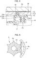
- FIG. 4 shows an enlarged view around the touch pad 7 in Fig. 2 .
- an upper elastic body holding portion 21e is formed in a projection shape and holds a support elastic body 23 formed by a coil spring.
- the support body 21 supports the touch pad 7 through the support elastic body 23 so as to press the touch pad 7 against the inner surface of the top surface portion 20c. It should be noted that if a configuration is provided in which the top surface portion 20c is not illuminated by a light emitter 17a, a reflector 30 may not be interposed and the upper elastic body holding portion 21e may be pressed directly against the touch pad 7.
- a film substrate 7b in which a drive electrode and a detection electrode, which are not shown, are arranged on one surface is attached to a circuit board 7c to be formed in a plate shape, and the ring-shaped reflector 30 formed from a synthetic resin is mounted on the lower surface side.
- a contact portion 30b is formed in contact with the lower surface of the touch pad 7
- an engagement projection 30a is formed on the contact portion 30b so as to project toward the top surface portion 20c
- a cylindrical projection 30c is formed on the contact portion 30b so as to project in the downward direction in the drawing
- a reflecting layer (not shown) is formed on a side facing the touch pad 7.
- the engagement projection 30a is engaged with an engaged hole 7d formed in the lower surface of the touch pad 7, whereby the touch pad 7 and the reflector 30 are integrated.
- the end portion of the upper elastic body holding portion 21e is fitted into a hollow portion of the cylindrical projection 30c, and the support elastic body 23 is supported in a compressed state.
- the light emitter 17a formed by an LED is provided on the lower surface side of the circuit board 7c constituting the touch pad 7, and the reflector 30 can reflect light from the light emitter 17a toward a side wall of the operation knob 20 to output the light to the front surface side of the operation knob 20.
- the top surface portion 20c of the operation knob 20 is configured such that light of a light emitter 17b on the base plate 10 is partially outputted to the outside through the interlocking shaft 32 and a shaft 20g which are formed from translucent resin.
- the light emitters 17a and 17b can emit light as appropriate during an operation of the operation body 6 or upon receipt of a result of an operation.
- the support elastic body 23 held by the support body 21 elastically contacts the reflector 30 integrated with the touch pad 7, thereby supporting the touch pad 7 while elastically urging the touch pad 7 at all times in a direction to be pressed against the top surface portion 20c of the operation knob 20.
- the gap between the touch pad 7 and the top surface portion 20c of the operation knob 20 can be kept uniform, and stable output can be obtained from the touch pad 7 at approach or contact of a finger with respect to the top surface portion 20c.
- output from the touch pad 7 can be stabilized with the simple configuration.
- the operation knob 20 freely rotates relative to the support body 21 and the touch pad 7 is supported by the support body 21, the operation knob 20 slides on the front surface of the touch pad 7 during its rotation.
- a spacer portion 20f is formed on the back surface side of the top surface portion 20c.
- the spacer portion 20f is formed on the back surface of the top surface portion 20c as two ring-shaped projections which extend along the circumferential direction and have different diameters, and is formed with a uniform height over its entire circumference such that the gap between the top surface portion 20c and the touch pad 7 is uniform over the entire circumference. If the spacer portion 20f is not present between the top surface portion 20c and the touch pad 7, a non-uniform minute gap ⁇ d (air layer) is present between the top surface portion 20c and the touch pad 7 due to warpage and waviness of the touch pad 7 and the like.
- ⁇ d air layer
- the capacitance does not greatly vary.
- a protective sheet (not shown) formed from polyethylene or the like and having a surface with less frictional resistance is provided on the front surface of the touch pad 7, in order to reduce friction on the operation knob 20.
- the spacer portion 20f is formed between the top surface portion 20c and the touch pad 7, when the operation knob 20 rotates, the operation knob 20 can smoothly slide on the front surface of the touch pad 7, and the gap between the top surface portion 20c and the touch pad 7 urged by the support elastic body 23 can be ensured stably.
- an input device having excellent controllability can be provided.
- the spacer portion 20f is integrally formed in the top surface portion 20c of the operation knob 20 but may be formed on the touch pad 7 side.
- the spacer portion may be a part independent from the operation knob 20 and the touch pad 7, and may be any part as long as it makes the gap between the top surface portion 20c and the front surface of the touch pad 7 uniform over the entire circumference.
- the operation knob 20 constituting the operation body 6 has the shaft 20g provided vertically so as to project downwardly from the back surface side of the top surface portion 20c.
- the touch pad 7 has a through hole 7a through which the shaft 20g is inserted into the space 21f.
- the space 21f is formed so as to extend from the inside of the base member 5 to the inside of the hollow support body 11.
- the interlocking shaft 32 is connected on an extension line from the end portion (the lower end portion in the drawing) of the shaft 20g.
- the shaft 20g and the interlocking shaft 32 are connected to each other through a cam member 31, move in the axial direction by a pressing operation of the operation body 6, and rotate in the circumferential direction by a rotation operation of the operation body 6.
- the cam member 31 includes an upper shaft insertion portion 31a which fixes the shaft 20g fitted therein and a lower shaft insertion portion 31b which fixes the upper end portion of the interlocking shaft 32 fitted therein, connects both shafts to each other, and a cam surface 31c is provided in a peripheral surface of the cam member 31.
- Fig. 5 shows a schematic cross-sectional view of the cam member 31 and the hollow support body 11.
- a cam surface 31b is formed in the peripheral surface of the cam member 31 and has a plurality of cam projections 31a.
- an elastic portion 13 is provided on the inner surface of the hollow support body 11 and formed by a leaf spring.
- a leaf spring projection 13a is formed in a bent manner at its center so as to project toward the cam member 31.
- the cam projections 31a are provided in the cam member 31 which connects the shaft 20g to the interlocking shaft 32, and the elastic portion 13 is provided on the base member 5 side.
- the cam projections may be provided on the base member 5 side, and the elastic portion may be provided on the shaft 20g side.
- a pressing movement portion 32b is formed in the interlocking shaft 32 so as to extend vertically in the space 21f and has a ring-shaped flat portion at its lower end.
- the pressing movement portion 32b faces the pressing detection portion 9 located on the base plate 10.
- the pressing movement portion 32b presses the pressing detection portion 9.
- the pressing movement portion 32b makes a detection movement for the pressing detection portion 9 with a pressing movement of the operation body 6.
- the pressing detection portion 9 is located on the base plate 10 and in a position facing the space 21f formed by the support body 21.
- a cylindrical code plate 33 is provided to the lower end portion of the interlocking shaft 32 and has a diameter larger than that of the interlocking shaft 32.
- the code plate 33 has a plurality of slits 33a formed on the lower end side of a peripheral surface thereof along the circumferential direction.
- a cable 14 is drawn from the base plate 10 and connected to the touch pad 7.
- the cable 14 extends outward of the outer peripheral surface of the support body 21 and is connected to a lower surface of the touch pad 7.
- the shaft 20g is provided in the operation knob 20 so as to extend through the through hole 7a formed in the touch pad 7 into the space 21f formed in the support body 21 and is liked to the code plate 33 and the pressing movement portion 32b in the space 21f, parts required to detect a rotation operation and a pressing operation of the operation body 6 can be located at a central portion of the input device 2.
- the rotation detection portion 8 and the pressing detection portion 9 can be located so as to face the space 21f, not outside the support body 21, the size of the input device 2 in the radial direction can be reduced and size reduction of the input device 2 can be achieved.
- the click mechanism formed by the cam member 31 and the elastic portion 13 can be located in the space 21f, the click mechanism can be made compact and provide a smooth click feel, and the size of the input device 2 in the radial direction can more effectively be reduced.
- the connection member between the shaft 20g and the interlocking shaft 32 is configured to serve as the click mechanism, specifically, the connection member is formed as the cam member 31, the entire device can be further reduced in size.
- the click mechanism can be provided at a position different from the bearing portion 22 which is a rotation support portion for the operation knob 20, it is unnecessary to receive a rotation load at the shaft 20g, and hence the shaft 20g can be formed with a small diameter and the through hole 7a formed in the touch pad 7 can be made small. Thus, performance deterioration caused by forming a hole in the touch pad 7 can be prevented.
- the bearing portion 22 which allows the inner ring portion 22b fixed to the support body 21 and the outer ring portion 22a fixed to the operation knob 20 to freely rotate relative to each other, allows the operation knob 20 to freely rotate along the peripheral surface of the support body 21, whereby an operation of the operation knob 20 can assuredly and smoothly be performed without backlash.
Landscapes
- Engineering & Computer Science (AREA)
- Theoretical Computer Science (AREA)
- General Engineering & Computer Science (AREA)
- General Physics & Mathematics (AREA)
- Physics & Mathematics (AREA)
- Human Computer Interaction (AREA)
- Automation & Control Theory (AREA)
- Chemical & Material Sciences (AREA)
- Combustion & Propulsion (AREA)
- Transportation (AREA)
- Mechanical Engineering (AREA)
- Position Input By Displaying (AREA)
- Switches With Compound Operations (AREA)
- Mechanical Control Devices (AREA)
Abstract
Description
- The present invention relates to an input device having at least an operation body on which a rotation operation is capable of being performed, and specifically relates to an input device including a touch pad which is provided on a back surface side of an operation body and detects approach or contact of a finger.
- As an input device provided in a center console of a vehicle or the like, an input device is known which includes an operation body freely rotated and reciprocated relative to a base member, in which the operation body includes an operation knob formed in a cylindrical shape having a top surface portion, in which a touch pad for detecting approach or contact of a finger with respect to the top surface portion is provided on a back surface side of the top surface portion constituting the operation knob, and in which an input is made by approach or contact of a finger with respect to the top surface portion of the operation knob as well as a rotation operation and a pressing operation of the operation body. Such an input device is, for example, an input device disclosed in International Publication No.
2010/000281 . - In an input device having a touch pad, it is necessary to provide a support body which supports the touch pad. In an existing input device, a support body is provided within a base member, a wire to the touch pad is located therein, and a detection portion for detecting a rotation operation and a pressing operation of an operation body is located on a peripheral portion of the support body. Thus, a space for locating the detection portion needs to be ensured outward in the radial direction of the input device, and this inhibits size reduction of the input device.
- The present invention is made in view of the problem described above and provides an input device which can be reduced in size in a radial direction thereof while including a touch pad and an operation body on which a rotation operation and a pressing operation are capable of being performed.
- In order to solve the problem described above, the present invention provides an input device including: a base member including a hollow support body; and an operation body supported so as to freely rotate relative to the hollow support body and freely reciprocate along a direction of a rotational axis. The operation body includes an operation knob formed in a cylindrical shape and having a top surface portion and a plate-shaped touch pad provided on a back side of the top surface portion for detecting approach or contact of a finger with respect to the top surface portion. The base member has a space formed so as to extend from an inside of the base member to an inside of the hollow support body.
- The operation knob has a shaft provided vertically so as to extend from a back surface of the top surface portion. The touch pad has a through hole through which the shaft is inserted into the space. A rotation detection portion for detecting a rotating movement of the operation body and a pressing detection portion for detecting a reciprocating movement of the operation body are provided. In the space, the shaft is linked to a rotating movement portion which makes a rotation detection movement for the rotation detection portion with a rotating movement of the operation body, and to a pressing movement portion which makes a pressing detection movement for the pressing detection portion with a reciprocating movement of the operation body.
- Further, in the input device according to the present invention, an interlocking shaft is located in the space and connected to the shaft, and the rotating movement portion and the pressing movement portion are provided in the interlocking shaft.
- Further, in the input device according to the present invention, the shaft and the interlocking shaft are connected to each other through a cam portion having a plurality of cam surfaces formed along a peripheral surface thereof, and an elastic portion is provided in the hollow support body and engages with and disengages from the cam surfaces with a rotating movement of the operation body.
- Further, in the input device according to the present invention, the rotation detection portion and the pressing detection portion are located so as to face the space.
- Further, in the input device according to the present invention, the operation body has a support body which rotationally supports the operation knob, and the support body is supported by the hollow support body so as to reciprocate along a direction of a rotational axis of the operation knob.
- Further, in the input device according to the present invention, the support body and the operation knob are allowed to freely rotate along a peripheral surface of the support body by a bearing portion which includes an inner ring portion fixed to the support body and an outer ring portion fixed to the operation knob, and the inner ring portion and the outer ring portion freely rotate relative to each other.
- According to the input device according to the present invention, the operation knob has the shaft provided vertically so as to extend from the back surface of the top surface portion, the touch pad has the through hole through which the shaft is inserted into the space, and in the space, the shaft is linked to the rotating movement portion which makes a rotation detection movement for the rotation detection portion with a rotating movement of the operation body, and to the pressing movement portion which makes a pressing detection movement for the pressing detection portion with a reciprocating movement of the operation body. Thus, parts required to detect a rotation operation and a pressing operation of the operation body can be located in a space below the capacitance type touch pad provided on the back side of the top surface portion of the operation knob, namely, in the space which extends from the inside of the base member to the inside of the support body, and it is unnecessary to locate the parts widely in the radial direction. Thus, size reduction in the radial direction can be achieved.
- In addition, according to the input device according to the present invention, the interlocking shaft is located in the space and connected to the shaft, and the rotating movement portion and the pressing movement portion are provided in the interlocking shaft. Thus, the shaft and the interlocking shaft can be connected to each other with a simple structure, and the shaft can be linked to the rotating movement portion and the pressing movement portion with a simple configuration.
- Further, according to the input device according to the present invention, the shaft and the interlocking shaft are connected to each other through the cam portion having the plurality of cam surfaces formed along the peripheral surface thereof, and the elastic portion is provided in the hollow support body and engages with and disengages from the cam surfaces with a rotating movement of the operation body. Thus, a click mechanism can be made compact and provide a smooth click feel, and a connection member between the shaft and the interlocking shaft is configured to serve as the click mechanism. Thus, the entire device can be further reduced in size.
- Further, according to the input device according to the present invention, the rotation detection portion and the pressing detection portion are located so as to face the space from the outside of the space. Thus, a space for locating parts can be effectively used, and size reduction can be achieved.
- Then, according to the input device according to the present invention, the operation body includes the support body which rotationally supports the operation knob, and the support body is supported by the hollow support body so as to reciprocate along the direction of the rotational axis of the operation knob. Thus, the click mechanism can be provided at a position different from a rotation support portion for the operation knob. Thus, it is unnecessary to receive a rotation load at the shaft, and hence the shaft can be formed with a small diameter and the through hole formed in the touch pad can be made small.
- Further, according to the input device according to the present invention, the support body and the operation knob are allowed to freely rotate along the peripheral surface of the support body by the bearing portion which includes the inner ring portion fixed to the support body and the outer ring portion fixed to the operation knob, and the inner ring portion and the outer ring portion freely rotate relative to each other. Thus, a smooth operation can assuredly be performed without backlash of the operation knob.
-
-
Fig. 1 is a front view of a center console including an input device according to an embodiment; -
Fig. 2 is a cross-sectional view taken along the II-II line inFig. 1 ; -
Fig. 3 is a cross-sectional view taken along the III-III line inFig. 1 ; -
Fig. 4 is an enlarged cross-sectional view of a relevant portion of a capacitance type touch pad inFig. 2 ; -
Fig. 5 is a schematic cross-sectional view of a cam member and a hollow cylindrical body; and -
Fig. 6 is a schematic cross-sectional view of a relevant portion along the VI-VI line inFig. 2 . - An embodiment of the present invention will be described with reference to the drawings.
Fig. 1 shows a front view of a center console 1 including aninput device 2 according to the embodiment. The center console 1 is located between a driver seat and a passenger seat of a vehicle. Theinput device 2 and switches 3 through which various inputs are made are located on a surface of the center console 1. - The
input device 2 of the embodiment includes: anoperation knob 20 which has a cylindrical shape with a bottom, is exposed in the vehicle interior, can be rotated along a circumferential direction thereof, and can be pressed in a direction perpendicular to the surface of the center console 1; and a plate-shaped capacitance type touch pad 7 (hereinafter, referred to merely as touch pad;Fig. 4 ) which is provided on the back side of thetop surface portion 20c and can detect approach or contact of a finger with respect to a surface of atop surface portion 20c of theoperation knob 20. -
Fig. 2 shows an enlarged cross-sectional view taken along the II-II line inFig. 1 around theinput device 2, andFig. 3 shows an enlarged cross-sectional view taken along the III-III line inFig. 1 around theinput device 2. Theinput device 2 of the embodiment is configured such that anoperation body 6 is mounted on ahollow support body 11 provided vertically so as to extend upright from a hollow base member 5 placed on abase plate 10, such that theoperation body 6 freely rotates and freely reciprocates in the vertical direction inFig. 2 (in the direction of the rotational axis) as described above. In a region of thebase plate 10 which faces the inner space of the base member 5, a rotation detection portion 8 (Fig. 3 ) which detects a rotating movement of theoperation body 6 and a pressing detection portion 9 (Fig. 2 ) which detects a reciprocating movement of theoperation body 6 are located. The internal space described above corresponds to aspace 21f described later and extends from the inside of the base member 5 to the inside of thehollow support body 11. Therotation detection portion 8 is configured as a photointerrupter which includes a light-receiving element and a light-emitting element which face each other across a lower end side (a side on which aslit 33a is formed) of acylindrical code plate 33 mounted on an interlockingshaft 32, and thepressing detection portion 9 is configured as a pressing switch. - The
operation body 6 includes theoperation knob 20 formed in a cylindrical shape having thetop surface portion 20c, and a hollowcylindrical support body 21 which rotationally holds theoperation knob 20 through abearing portion 22. Meanwhile, thesupport body 21 freely reciprocates relative to the hollow support body 11 (the base member 5) together with theoperation knob 20 in the vertical direction in the drawing (in the direction of the rotational axis). Thus, since theoperation knob 20 freely rotates relative to thesupport body 21 only along the circumferential direction thereof, theoperation knob 20 freely rotates relative to the base member 5. -
Fig. 6 shows a schematic cross-sectional view of a relevant portion along the VI-VI line inFig. 2 . As shown inFig. 6 , thesupport body 21 has, in an inner peripheral surface (inner wall) thereof, a plurality of grooves (recesses) 21a extending in the vertical direction, and thehollow support body 11 provided vertically on the base member 5 has, in an outer peripheral surface (outer wall) thereof, a guide rail (projection) 11a which engages with eachgroove 21a so as to be guided by thegroove 21a. Due to this configuration, thesupport body 21 is assuredly and stably supported so as to freely reciprocate relative to the hollow support body 11 (the base member 5) together with theoperation knob 20 in the vertical direction in the drawing. Thegrooves 21a may be formed in the outer wall of thehollow support body 11 and theguide rails 11a may be formed in the inner wall of thesupport body 21. Thehollow support body 11 serves as an operation body support portion, namely, serves to support theoperation body 6 such that theoperation body 6 freely reciprocates only in the vertical direction, and thus may be formed in a hollow cylindrical shape. Thesupport body 21 may have a space having a polygonal transverse cross section, and thehollow support body 11 may have an outer shape corresponding to the space shape of thesupport body 21. - On the base member 5, the
hollow support body 11 is formed in such a position that theoperation body 6 freely rotates and freely reciprocates in the vertical direction. Thehollow support body 11 is formed so as to have a step in a peripheral surface thereof, and thesupport body 21 is provided outside thehollow support body 11 so as to cover its peripheral surface. Thesupport body 21 has a hollow cylindrical shape, and thus has thespace 21f formed therein. - As shown in
Fig. 2 , anaccommodation portion 12 is formed outside a base end portion of thehollow support body 11 on the base member 5 so as to have a recess shape and so as to extend in the circumferential direction over 180 degrees. Alower end projection 21c is formed in a lower end portion of thesupport body 21 and accommodated in theaccommodation portion 12. Thelower end projection 21c is moveable vertically within theaccommodation portion 12. In addition, a lower elasticbody holding portion 21d is formed in a lower end portion of thelower end projection 21c and holds a pressingelastic body 24 which is formed by a coil spring as an elastic body in the present invention. When thesupport body 21 moves downwardly, the pressingelastic body 24 generates a repelling force against the movement. - As described above, the
support body 21 is allowed to freely move vertically relative to the base member 5 due to theaccommodation portion 12 and is supported by the base member 5 through the pressingelastic body 24. Thus, thesupport body 21 can make a reciprocating movement in which thesupport body 21 moves downwardly relative to the base member 5 by a pressing theoperation body 6 and when the pressing is released, thesupport body 21 returns to the original position by the repelling force of the pressingelastic body 24. - The
operation knob 20 is composed of anupper member 20a having thetop surface portion 20c, and alower member 20b which is fixed to a lower portion of theupper member 20a and inserted in the base member 5. - The
lower member 20b of theoperation knob 20 has a diameter larger than the outer diameter of thesupport body 21 and faces the outer peripheral surface of thesupport body 21. The bearingportion 22, which allows theoperation knob 20 to freely rotate relative to thesupport body 21, is formed from a ring-shaped bearing member and is configured such that anouter ring portion 22a and aninner ring portion 22b freely rotate relative to each other. Specifically, a rolling bearing, a plain bearing, a magnetic bearing, a fluid dynamic bearing, or the like can be used. - The
outer ring portion 22a of the bearingportion 22 is fixed at its outer peripheral surface to the inner surface side of the operation knob 20 (thelower member 20b), and theinner ring portion 22b of the bearingportion 22 is fixed at its inner peripheral surface to the outer surface side of thesupport body 21. Thus, theoperation knob 20 is supported so as to freely rotate relative to thesupport body 21 in the circumferential direction thereof. - As described above, the
operation body 6 is composed of thesupport body 21 and theoperation knob 20, thesupport body 21 is configured to be supported by the base member 5 through the pressingelastic body 24 and to freely reciprocate vertically along thehollow support body 11, and theoperation knob 20 is configured to freely rotate relative to thesupport body 21 through the bearingportion 22, thereby providing a structure in which theoperation knob 20 is mounted on thesupport body 21 so as to freely rotate relative to thesupport body 21 which reciprocates relative to the base member 5. Thus, in the input device of the present embodiment, the reciprocating movement and the rotation operation of theoperation knob 20 can assuredly be performed in different configurations, respectively, unlike the case where these operations are performed through the gap between a hollow cylindrical bearing portion and a cylindrical operation body (operation shaft) provided around the bearing portion as in the related art, and hence a smooth operation is possible without backlash. - Next, a structure to support the
touch pad 7 will be described.Fig. 4 shows an enlarged view around thetouch pad 7 inFig. 2 . In an upper end portion of thesupport body 21, an upper elasticbody holding portion 21e is formed in a projection shape and holds a supportelastic body 23 formed by a coil spring. As described in detail later, thesupport body 21 supports thetouch pad 7 through the supportelastic body 23 so as to press thetouch pad 7 against the inner surface of thetop surface portion 20c. It should be noted that if a configuration is provided in which thetop surface portion 20c is not illuminated by alight emitter 17a, areflector 30 may not be interposed and the upper elasticbody holding portion 21e may be pressed directly against thetouch pad 7. - In the
touch pad 7, afilm substrate 7b in which a drive electrode and a detection electrode, which are not shown, are arranged on one surface is attached to acircuit board 7c to be formed in a plate shape, and the ring-shapedreflector 30 formed from a synthetic resin is mounted on the lower surface side. In thereflector 30, a contact portion 30b is formed in contact with the lower surface of thetouch pad 7, anengagement projection 30a is formed on the contact portion 30b so as to project toward thetop surface portion 20c, acylindrical projection 30c is formed on the contact portion 30b so as to project in the downward direction in the drawing, and a reflecting layer (not shown) is formed on a side facing thetouch pad 7. Theengagement projection 30a is engaged with an engagedhole 7d formed in the lower surface of thetouch pad 7, whereby thetouch pad 7 and thereflector 30 are integrated. As shown inFig. 4 , the end portion of the upper elasticbody holding portion 21e is fitted into a hollow portion of thecylindrical projection 30c, and the supportelastic body 23 is supported in a compressed state. As shown inFig. 3 , thelight emitter 17a formed by an LED is provided on the lower surface side of thecircuit board 7c constituting thetouch pad 7, and thereflector 30 can reflect light from thelight emitter 17a toward a side wall of theoperation knob 20 to output the light to the front surface side of theoperation knob 20. In addition, thetop surface portion 20c of theoperation knob 20 is configured such that light of alight emitter 17b on thebase plate 10 is partially outputted to the outside through the interlockingshaft 32 and ashaft 20g which are formed from translucent resin. Thelight emitters operation body 6 or upon receipt of a result of an operation. - As described above, the support
elastic body 23 held by thesupport body 21 elastically contacts thereflector 30 integrated with thetouch pad 7, thereby supporting thetouch pad 7 while elastically urging thetouch pad 7 at all times in a direction to be pressed against thetop surface portion 20c of theoperation knob 20. Thus, if theoperation knob 20 is tilted relative to the base member 5 (the hollow support body 11), the gap between thetouch pad 7 and thetop surface portion 20c of theoperation knob 20 can be kept uniform, and stable output can be obtained from thetouch pad 7 at approach or contact of a finger with respect to thetop surface portion 20c. Thus, output from thetouch pad 7 can be stabilized with the simple configuration. - Further, since the
operation knob 20 freely rotates relative to thesupport body 21 and thetouch pad 7 is supported by thesupport body 21, theoperation knob 20 slides on the front surface of thetouch pad 7 during its rotation. In order to enable smooth slide, aspacer portion 20f is formed on the back surface side of thetop surface portion 20c. - For example, the
spacer portion 20f is formed on the back surface of thetop surface portion 20c as two ring-shaped projections which extend along the circumferential direction and have different diameters, and is formed with a uniform height over its entire circumference such that the gap between thetop surface portion 20c and thetouch pad 7 is uniform over the entire circumference. If thespacer portion 20f is not present between thetop surface portion 20c and thetouch pad 7, a non-uniform minute gap Δd (air layer) is present between thetop surface portion 20c and thetouch pad 7 due to warpage and waviness of thetouch pad 7 and the like. Thus, for example, when the gap Δd varies due to tilt of the operation knob 20 (thetop surface portion 20c) during a rotation operation, an erroneous operation may occur as if a finger input was performed. In addition, when the gap Δd varies at finger input, output corresponding to the finger position may be unstable. On the other hand, in the configuration having thespacer portion 20f (height d = 0.2 mm >> Δd), even when a gap Δd is present due to warpage and waviness of thetouch pad 7 and the like, a capacitance corresponding to 1/(d+Δd) occurs between thetop surface portion 20c and thetouch pad 7. Thus, even when the gap Δd varies depending on an operation position of a finger, the capacitance does not greatly vary. As a result, even when thetop surface portion 20c is tilted during a rotation operation, there is no possibility that an erroneous operation will occur, and output corresponding to the position of the finger can be more stabilized, which is preferable. Moreover, a protective sheet (not shown) formed from polyethylene or the like and having a surface with less frictional resistance is provided on the front surface of thetouch pad 7, in order to reduce friction on theoperation knob 20. - As described above, since the
spacer portion 20f is formed between thetop surface portion 20c and thetouch pad 7, when theoperation knob 20 rotates, theoperation knob 20 can smoothly slide on the front surface of thetouch pad 7, and the gap between thetop surface portion 20c and thetouch pad 7 urged by the supportelastic body 23 can be ensured stably. Thus, an input device having excellent controllability can be provided. - In the present embodiment, the
spacer portion 20f is integrally formed in thetop surface portion 20c of theoperation knob 20 but may be formed on thetouch pad 7 side. In addition, the spacer portion may be a part independent from theoperation knob 20 and thetouch pad 7, and may be any part as long as it makes the gap between thetop surface portion 20c and the front surface of thetouch pad 7 uniform over the entire circumference. - Next, the
operation body 6, therotation detection portion 8, and thepressing detection portion 9 will be described. As shown inFigs. 2 and3 , theoperation knob 20 constituting theoperation body 6 has theshaft 20g provided vertically so as to project downwardly from the back surface side of thetop surface portion 20c. Thetouch pad 7 has a throughhole 7a through which theshaft 20g is inserted into thespace 21f. Thespace 21f is formed so as to extend from the inside of the base member 5 to the inside of thehollow support body 11. - In the
space 21f, the interlockingshaft 32 is connected on an extension line from the end portion (the lower end portion in the drawing) of theshaft 20g. Theshaft 20g and the interlockingshaft 32 are connected to each other through acam member 31, move in the axial direction by a pressing operation of theoperation body 6, and rotate in the circumferential direction by a rotation operation of theoperation body 6. Thecam member 31 includes an uppershaft insertion portion 31a which fixes theshaft 20g fitted therein and a lowershaft insertion portion 31b which fixes the upper end portion of the interlockingshaft 32 fitted therein, connects both shafts to each other, and acam surface 31c is provided in a peripheral surface of thecam member 31. -
Fig. 5 shows a schematic cross-sectional view of thecam member 31 and thehollow support body 11. As shown inFig. 5 , acam surface 31b is formed in the peripheral surface of thecam member 31 and has a plurality ofcam projections 31a. Meanwhile, anelastic portion 13 is provided on the inner surface of thehollow support body 11 and formed by a leaf spring. In theelastic portion 13, aleaf spring projection 13a is formed in a bent manner at its center so as to project toward thecam member 31. When theoperation knob 20 is rotated and thecam member 31 rotates, the end portion of thecam projection 31a engages with and disengages from theleaf spring projection 13a at each predetermined angle, thereby providing a click feel for the rotation operation of theoperation knob 20. - As described above, in the present embodiment, the
cam projections 31a are provided in thecam member 31 which connects theshaft 20g to the interlockingshaft 32, and theelastic portion 13 is provided on the base member 5 side. However, the cam projections may be provided on the base member 5 side, and the elastic portion may be provided on theshaft 20g side. - As shown in
Fig. 2 , apressing movement portion 32b is formed in the interlockingshaft 32 so as to extend vertically in thespace 21f and has a ring-shaped flat portion at its lower end. Thepressing movement portion 32b faces thepressing detection portion 9 located on thebase plate 10. When theoperation body 6 is pressed and theshaft 20g and the interlockingshaft 32 move downwardly along the axial direction, thepressing movement portion 32b presses thepressing detection portion 9. In other words, thepressing movement portion 32b makes a detection movement for thepressing detection portion 9 with a pressing movement of theoperation body 6. Thus, the pressing operation of theoperation body 6 can be detected. In order to face thepressing movement portion 32b provided in the interlockingshaft 32, thepressing detection portion 9 is located on thebase plate 10 and in a position facing thespace 21f formed by thesupport body 21. - Further, as shown in
Fig. 3 , acylindrical code plate 33 is provided to the lower end portion of the interlockingshaft 32 and has a diameter larger than that of the interlockingshaft 32. Thecode plate 33 has a plurality ofslits 33a formed on the lower end side of a peripheral surface thereof along the circumferential direction. When theoperation body 6 is rotated and theshaft 20g and the interlockingshaft 32 rotate in the circumferential direction, its rotation position is detected by therotation detection portion 8, and the rotation operation of theoperation body 6 can be detected. - As shown in
Fig. 3 , for power supply and output of data, acable 14 is drawn from thebase plate 10 and connected to thetouch pad 7. Thecable 14 extends outward of the outer peripheral surface of thesupport body 21 and is connected to a lower surface of thetouch pad 7. - As described above, since the
shaft 20g is provided in theoperation knob 20 so as to extend through the throughhole 7a formed in thetouch pad 7 into thespace 21f formed in thesupport body 21 and is liked to thecode plate 33 and thepressing movement portion 32b in thespace 21f, parts required to detect a rotation operation and a pressing operation of theoperation body 6 can be located at a central portion of theinput device 2. In particular, since therotation detection portion 8 and thepressing detection portion 9 can be located so as to face thespace 21f, not outside thesupport body 21, the size of theinput device 2 in the radial direction can be reduced and size reduction of theinput device 2 can be achieved. - Further, since the click mechanism formed by the
cam member 31 and theelastic portion 13 can be located in thespace 21f, the click mechanism can be made compact and provide a smooth click feel, and the size of theinput device 2 in the radial direction can more effectively be reduced. In addition, since the connection member between theshaft 20g and the interlockingshaft 32 is configured to serve as the click mechanism, specifically, the connection member is formed as thecam member 31, the entire device can be further reduced in size. Moreover, since the click mechanism can be provided at a position different from the bearingportion 22 which is a rotation support portion for theoperation knob 20, it is unnecessary to receive a rotation load at theshaft 20g, and hence theshaft 20g can be formed with a small diameter and the throughhole 7a formed in thetouch pad 7 can be made small. Thus, performance deterioration caused by forming a hole in thetouch pad 7 can be prevented. - Further, regarding the
support body 21 and theoperation knob 20 constituting theoperation body 6, the bearingportion 22, which allows theinner ring portion 22b fixed to thesupport body 21 and theouter ring portion 22a fixed to theoperation knob 20 to freely rotate relative to each other, allows theoperation knob 20 to freely rotate along the peripheral surface of thesupport body 21, whereby an operation of theoperation knob 20 can assuredly and smoothly be performed without backlash. - Although the embodiment of the present invention has been described above, the application of the present invention is not limited to the embodiment and may be variously applied within the scope of the technical idea thereof.
Claims (6)
- An input device comprising:a base member (5) including a hollow support body (11); andan operation body (6) supported so as to freely rotate relative to the hollow support body and freely reciprocate along a direction of a rotational axis, the operation body including an operation knob (20) formed in a cylindrical shape and having a top surface portion (20c) and a plate-shaped touch pad (7) provided on a back side of the top surface portion for detecting approach or contact of a finger with respect to the top surface portion, whereinthe base member has a space (21f) formed so as to extend from an inside of the base member to an inside of the hollow support body,the operation knob has a shaft (20g) provided vertically so as to extend from a back surface of the top surface portion,the touch pad has a through hole (7a) through which the shaft is inserted into the space,a rotation detection portion (8) for detecting a rotating movement of the operation body and a pressing detection portion (9) for detecting a reciprocating movement of the operation body are provided, andin the space, the shaft is linked to a rotating movement portion which makes a rotation detection movement for the rotation detection portion with a rotating movement of the operation body, and to a pressing movement portion (32b) which makes a pressing detection movement for the pressing detection portion with a reciprocating movement of the operation body.
- The input device according to Claim 1, wherein
an interlocking shaft (32) is located in the space and connected to the shaft, and
the rotating movement portion and the pressing movement portion are provided in the interlocking shaft. - The input device according to Claim 2, wherein
the shaft and the interlocking shaft are connected to each other through a cam portion (31c) having a plurality of cam surfaces (31d) formed along a peripheral surface thereof, and
an elastic portion (13) is provided in the hollow support body and engages with and disengages from the cam surfaces with a rotating movement of the operation body. - The input device according to any of the preceding Claims, wherein the rotation detection portion and the pressing detection portion are located so as to face the space.
- The input device according to any of the preceding Claims, wherein
the operation body includes a support body (21) which rotationally supports the operation knob, and
the support body is supported by the hollow support body so as to reciprocate along a direction of a rotational axis of the operation knob. - The input device according to Claim 5, wherein the support body and the operation knob are allowed to freely rotate along a peripheral surface of the support body by a bearing portion (22) which includes an inner ring portion (22a) fixed to the support body and an outer ring portion (22b) fixed to the operation knob, the inner ring portion and the outer ring portion freely rotating relative to each other.
Applications Claiming Priority (1)
| Application Number | Priority Date | Filing Date | Title |
|---|---|---|---|
| JP2011089776A JP5626591B2 (en) | 2011-04-14 | 2011-04-14 | Input device |
Publications (3)
| Publication Number | Publication Date |
|---|---|
| EP2511796A2 true EP2511796A2 (en) | 2012-10-17 |
| EP2511796A3 EP2511796A3 (en) | 2015-07-22 |
| EP2511796B1 EP2511796B1 (en) | 2017-10-25 |
Family
ID=45874694
Family Applications (1)
| Application Number | Title | Priority Date | Filing Date |
|---|---|---|---|
| EP12159725.6A Active EP2511796B1 (en) | 2011-04-14 | 2012-03-15 | Input apparatus comprising a touch sensitive input device and a rotatable input device |
Country Status (4)
| Country | Link |
|---|---|
| US (1) | US8884933B2 (en) |
| EP (1) | EP2511796B1 (en) |
| JP (1) | JP5626591B2 (en) |
| CN (1) | CN102737898B (en) |
Cited By (1)
| Publication number | Priority date | Publication date | Assignee | Title |
|---|---|---|---|---|
| EP3014400B1 (en) * | 2013-08-09 | 2020-06-03 | Apple Inc. | Tactile switch for an electronic device |
Families Citing this family (24)
| Publication number | Priority date | Publication date | Assignee | Title |
|---|---|---|---|---|
| JP2554964Y2 (en) | 1993-07-28 | 1997-11-19 | 富士ロビン株式会社 | Driven wheel direction switching device for trucks |
| DE102013101339A1 (en) * | 2013-02-12 | 2014-08-14 | Dr. Ing. H.C. F. Porsche Aktiengesellschaft | operating element |
| JP2016153926A (en) * | 2013-06-25 | 2016-08-25 | パナソニックIpマネジメント株式会社 | Input device |
| CN104154571A (en) * | 2013-09-02 | 2014-11-19 | 李秋达 | Multifunctional extension and application of gas plug valve assembly and knob |
| KR101510013B1 (en) * | 2013-12-18 | 2015-04-07 | 현대자동차주식회사 | Multi handling system and method using touch pad |
| ES2539417B1 (en) * | 2015-03-03 | 2016-01-25 | Seat, S.A. | Actuator device for control unit and fixing procedure of an actuator device for control unit |
| CN107533381B (en) * | 2015-04-23 | 2020-10-30 | 阿尔卑斯阿尔派株式会社 | Input assisting device and input system |
| EP3242307B1 (en) * | 2016-05-03 | 2020-10-28 | Electrolux Appliances Aktiebolag | Switching element for a control device |
| TW201743074A (en) | 2016-06-01 | 2017-12-16 | 原相科技股份有限公司 | Measuring device and its operating method |
| CN110986917B (en) * | 2016-06-13 | 2021-10-01 | 原相科技股份有限公司 | Track sensing system and track sensing method therefor |
| JP2018034675A (en) * | 2016-08-31 | 2018-03-08 | 株式会社デンソー | Operation device |
| US11106291B2 (en) * | 2017-10-11 | 2021-08-31 | Mitsubishi Electric Corporation | Knob and input device |
| JP6857778B2 (en) * | 2018-03-26 | 2021-04-14 | アルプスアルパイン株式会社 | Switch device |
| JP7064934B2 (en) * | 2018-04-19 | 2022-05-11 | スタンレー電気株式会社 | Input device |
| JP7077924B2 (en) * | 2018-11-29 | 2022-05-31 | 株式会社デンソー | Switch device |
| CN111452583B (en) * | 2019-01-21 | 2023-09-12 | 宁波福尔达智能科技股份有限公司 | Air conditioner controller for vehicle |
| TWI704444B (en) * | 2019-07-09 | 2020-09-11 | 宏碁股份有限公司 | Touch pad structure |
| CN112241209B (en) * | 2019-07-17 | 2023-08-01 | 宏碁股份有限公司 | Touch panel structure |
| KR102730517B1 (en) | 2019-11-14 | 2024-11-13 | 현대자동차주식회사 | Rattle reducing device for dial type shift control apparatus |
| KR102676723B1 (en) * | 2019-11-14 | 2024-06-18 | 현대자동차주식회사 | Dial type shift control apparatus for electronic shift system |
| KR102812073B1 (en) | 2019-11-14 | 2025-05-22 | 현대자동차주식회사 | Ambient light device for dial type shift control apparatus |
| CN111243884A (en) * | 2020-02-17 | 2020-06-05 | 山东临工工程机械有限公司 | Bus KEYPAD for engineering machinery |
| WO2022202301A1 (en) * | 2021-03-25 | 2022-09-29 | アルプスアルパイン株式会社 | Rotary shifter |
| IT202200007877A1 (en) | 2022-04-21 | 2023-10-21 | Ferrari Spa | CONTROL KNOB FOR A MOTOR VEHICLE |
Citations (1)
| Publication number | Priority date | Publication date | Assignee | Title |
|---|---|---|---|---|
| WO2010000281A1 (en) | 2008-06-30 | 2010-01-07 | Alps Electric Europe Gmbh | Input apparatus comprising a touch sensitive input device and a rotatable input device |
Family Cites Families (12)
| Publication number | Priority date | Publication date | Assignee | Title |
|---|---|---|---|---|
| JP3222714B2 (en) * | 1995-01-24 | 2001-10-29 | 松下電器産業株式会社 | Pressing and rotating electronic parts |
| US7038667B1 (en) * | 1998-10-26 | 2006-05-02 | Immersion Corporation | Mechanisms for control knobs and other interface devices |
| JP2004146090A (en) * | 2002-10-22 | 2004-05-20 | Pioneer Electronic Corp | Multifunction operation unit |
| JP4184821B2 (en) * | 2003-02-07 | 2008-11-19 | アルプス電気株式会社 | Rotary push switch device |
| JP2007004254A (en) * | 2005-06-21 | 2007-01-11 | Alps Electric Co Ltd | Kinesthetic sense giving type input device |
| EP1961025B1 (en) * | 2005-07-19 | 2016-03-30 | Preh GmbH | Control button comprising integrated functionality |
| JP4700432B2 (en) * | 2005-07-29 | 2011-06-15 | 本田技研工業株式会社 | Vehicle control device |
| DE602006014066D1 (en) * | 2005-08-05 | 2010-06-17 | Niles Co Ltd | Multidirectional input device |
| JP4551915B2 (en) * | 2007-07-03 | 2010-09-29 | ホシデン株式会社 | Combined operation type input device |
| JP2009092543A (en) * | 2007-10-10 | 2009-04-30 | Ishida Co Ltd | Weighing device |
| US8436814B2 (en) * | 2008-09-25 | 2013-05-07 | Denso Corporation | In-vehicle manipulation apparatus and in-vehicle input apparatus |
| JP2010287351A (en) * | 2009-06-09 | 2010-12-24 | Toto Ltd | Operation input device, and water cock device |
-
2011
- 2011-04-14 JP JP2011089776A patent/JP5626591B2/en active Active
-
2012
- 2012-02-22 CN CN201210042248.5A patent/CN102737898B/en active Active
- 2012-03-15 EP EP12159725.6A patent/EP2511796B1/en active Active
- 2012-04-04 US US13/439,408 patent/US8884933B2/en active Active
Patent Citations (1)
| Publication number | Priority date | Publication date | Assignee | Title |
|---|---|---|---|---|
| WO2010000281A1 (en) | 2008-06-30 | 2010-01-07 | Alps Electric Europe Gmbh | Input apparatus comprising a touch sensitive input device and a rotatable input device |
Cited By (1)
| Publication number | Priority date | Publication date | Assignee | Title |
|---|---|---|---|---|
| EP3014400B1 (en) * | 2013-08-09 | 2020-06-03 | Apple Inc. | Tactile switch for an electronic device |
Also Published As
| Publication number | Publication date |
|---|---|
| JP5626591B2 (en) | 2014-11-19 |
| JP2012221439A (en) | 2012-11-12 |
| CN102737898A (en) | 2012-10-17 |
| US8884933B2 (en) | 2014-11-11 |
| EP2511796A3 (en) | 2015-07-22 |
| CN102737898B (en) | 2014-10-15 |
| EP2511796B1 (en) | 2017-10-25 |
| US20120262393A1 (en) | 2012-10-18 |
Similar Documents
| Publication | Publication Date | Title |
|---|---|---|
| EP2511796B1 (en) | Input apparatus comprising a touch sensitive input device and a rotatable input device | |
| EP2511795A2 (en) | Input Device | |
| JP5593569B2 (en) | Input device | |
| US7745749B2 (en) | Dial controller | |
| US20120038495A1 (en) | Operation feeling imparting type trackball device | |
| JP5219988B2 (en) | Combined operation type input device | |
| CN103282850B (en) | Rotary/push operating device for a man-machine interface | |
| JP5797444B2 (en) | Joystick device | |
| US11364435B2 (en) | Operation device | |
| US10133296B2 (en) | Multidirectional operating device | |
| JP2019029358A (en) | Touchpad guided by linear bearing | |
| US20120286978A1 (en) | Operation input device | |
| US20120286977A1 (en) | Operation input device | |
| EP3915813B1 (en) | Controller for vehicle air conditioner | |
| US7382557B1 (en) | Fine adjustment mechanism for zoom lens assembly | |
| US9003913B2 (en) | Operation input device | |
| JP2014175194A (en) | Input device | |
| JP2016091981A (en) | Switch device | |
| JP2012204198A (en) | Wiring board and input device with the same | |
| JP4476562B2 (en) | Operating device | |
| JP2009283311A (en) | Inputting device and electronic equipment having this inputting device | |
| JP2024093688A (en) | pointing device | |
| JP2017147174A (en) | Rotary electronic component with click mechanism | |
| JP2020095844A (en) | Operating device | |
| JP2021165918A (en) | Operating device |
Legal Events
| Date | Code | Title | Description |
|---|---|---|---|
| PUAI | Public reference made under article 153(3) epc to a published international application that has entered the european phase |
Free format text: ORIGINAL CODE: 0009012 |
|
| AK | Designated contracting states |
Kind code of ref document: A2 Designated state(s): AL AT BE BG CH CY CZ DE DK EE ES FI FR GB GR HR HU IE IS IT LI LT LU LV MC MK MT NL NO PL PT RO RS SE SI SK SM TR |
|
| AX | Request for extension of the european patent |
Extension state: BA ME |
|
| REG | Reference to a national code |
Ref country code: DE Ref legal event code: R079 Ref document number: 602012038844 Country of ref document: DE Free format text: PREVIOUS MAIN CLASS: G06F0003033000 Ipc: B60K0037060000 |
|
| PUAL | Search report despatched |
Free format text: ORIGINAL CODE: 0009013 |
|
| AK | Designated contracting states |
Kind code of ref document: A3 Designated state(s): AL AT BE BG CH CY CZ DE DK EE ES FI FR GB GR HR HU IE IS IT LI LT LU LV MC MK MT NL NO PL PT RO RS SE SI SK SM TR |
|
| AX | Request for extension of the european patent |
Extension state: BA ME |
|
| RIC1 | Information provided on ipc code assigned before grant |
Ipc: H01H 25/00 20060101ALI20150616BHEP Ipc: G06F 3/033 20130101ALI20150616BHEP Ipc: G05G 1/02 20060101ALI20150616BHEP Ipc: G05G 1/04 20060101ALI20150616BHEP Ipc: G05G 1/08 20060101ALI20150616BHEP Ipc: H03K 17/96 20060101ALI20150616BHEP Ipc: B60K 37/06 20060101AFI20150616BHEP Ipc: G06F 3/041 20060101ALI20150616BHEP |
|
| 17P | Request for examination filed |
Effective date: 20160121 |
|
| RBV | Designated contracting states (corrected) |
Designated state(s): AL AT BE BG CH CY CZ DE DK EE ES FI FR GB GR HR HU IE IS IT LI LT LU LV MC MK MT NL NO PL PT RO RS SE SI SK SM TR |
|
| GRAP | Despatch of communication of intention to grant a patent |
Free format text: ORIGINAL CODE: EPIDOSNIGR1 |
|
| INTG | Intention to grant announced |
Effective date: 20170612 |
|
| GRAS | Grant fee paid |
Free format text: ORIGINAL CODE: EPIDOSNIGR3 |
|
| GRAA | (expected) grant |
Free format text: ORIGINAL CODE: 0009210 |
|
| AK | Designated contracting states |
Kind code of ref document: B1 Designated state(s): AL AT BE BG CH CY CZ DE DK EE ES FI FR GB GR HR HU IE IS IT LI LT LU LV MC MK MT NL NO PL PT RO RS SE SI SK SM TR |
|
| REG | Reference to a national code |
Ref country code: GB Ref legal event code: FG4D |
|
| REG | Reference to a national code |
Ref country code: CH Ref legal event code: EP |
|
| REG | Reference to a national code |
Ref country code: AT Ref legal event code: REF Ref document number: 939590 Country of ref document: AT Kind code of ref document: T Effective date: 20171115 |
|
| REG | Reference to a national code |
Ref country code: IE Ref legal event code: FG4D |
|
| REG | Reference to a national code |
Ref country code: DE Ref legal event code: R096 Ref document number: 602012038844 Country of ref document: DE |
|
| REG | Reference to a national code |
Ref country code: NL Ref legal event code: MP Effective date: 20171025 |
|
| REG | Reference to a national code |
Ref country code: LT Ref legal event code: MG4D |
|
| REG | Reference to a national code |
Ref country code: AT Ref legal event code: MK05 Ref document number: 939590 Country of ref document: AT Kind code of ref document: T Effective date: 20171025 |
|
| PG25 | Lapsed in a contracting state [announced via postgrant information from national office to epo] |
Ref country code: NL Free format text: LAPSE BECAUSE OF FAILURE TO SUBMIT A TRANSLATION OF THE DESCRIPTION OR TO PAY THE FEE WITHIN THE PRESCRIBED TIME-LIMIT Effective date: 20171025 |
|
| PG25 | Lapsed in a contracting state [announced via postgrant information from national office to epo] |
Ref country code: FI Free format text: LAPSE BECAUSE OF FAILURE TO SUBMIT A TRANSLATION OF THE DESCRIPTION OR TO PAY THE FEE WITHIN THE PRESCRIBED TIME-LIMIT Effective date: 20171025 Ref country code: NO Free format text: LAPSE BECAUSE OF FAILURE TO SUBMIT A TRANSLATION OF THE DESCRIPTION OR TO PAY THE FEE WITHIN THE PRESCRIBED TIME-LIMIT Effective date: 20180125 Ref country code: SE Free format text: LAPSE BECAUSE OF FAILURE TO SUBMIT A TRANSLATION OF THE DESCRIPTION OR TO PAY THE FEE WITHIN THE PRESCRIBED TIME-LIMIT Effective date: 20171025 Ref country code: LT Free format text: LAPSE BECAUSE OF FAILURE TO SUBMIT A TRANSLATION OF THE DESCRIPTION OR TO PAY THE FEE WITHIN THE PRESCRIBED TIME-LIMIT Effective date: 20171025 Ref country code: ES Free format text: LAPSE BECAUSE OF FAILURE TO SUBMIT A TRANSLATION OF THE DESCRIPTION OR TO PAY THE FEE WITHIN THE PRESCRIBED TIME-LIMIT Effective date: 20171025 |
|
| PG25 | Lapsed in a contracting state [announced via postgrant information from national office to epo] |
Ref country code: RS Free format text: LAPSE BECAUSE OF FAILURE TO SUBMIT A TRANSLATION OF THE DESCRIPTION OR TO PAY THE FEE WITHIN THE PRESCRIBED TIME-LIMIT Effective date: 20171025 Ref country code: IS Free format text: LAPSE BECAUSE OF FAILURE TO SUBMIT A TRANSLATION OF THE DESCRIPTION OR TO PAY THE FEE WITHIN THE PRESCRIBED TIME-LIMIT Effective date: 20180225 Ref country code: BG Free format text: LAPSE BECAUSE OF FAILURE TO SUBMIT A TRANSLATION OF THE DESCRIPTION OR TO PAY THE FEE WITHIN THE PRESCRIBED TIME-LIMIT Effective date: 20180125 Ref country code: GR Free format text: LAPSE BECAUSE OF FAILURE TO SUBMIT A TRANSLATION OF THE DESCRIPTION OR TO PAY THE FEE WITHIN THE PRESCRIBED TIME-LIMIT Effective date: 20180126 Ref country code: LV Free format text: LAPSE BECAUSE OF FAILURE TO SUBMIT A TRANSLATION OF THE DESCRIPTION OR TO PAY THE FEE WITHIN THE PRESCRIBED TIME-LIMIT Effective date: 20171025 Ref country code: HR Free format text: LAPSE BECAUSE OF FAILURE TO SUBMIT A TRANSLATION OF THE DESCRIPTION OR TO PAY THE FEE WITHIN THE PRESCRIBED TIME-LIMIT Effective date: 20171025 Ref country code: AT Free format text: LAPSE BECAUSE OF FAILURE TO SUBMIT A TRANSLATION OF THE DESCRIPTION OR TO PAY THE FEE WITHIN THE PRESCRIBED TIME-LIMIT Effective date: 20171025 |
|
| REG | Reference to a national code |
Ref country code: DE Ref legal event code: R097 Ref document number: 602012038844 Country of ref document: DE |
|
| PG25 | Lapsed in a contracting state [announced via postgrant information from national office to epo] |
Ref country code: CZ Free format text: LAPSE BECAUSE OF FAILURE TO SUBMIT A TRANSLATION OF THE DESCRIPTION OR TO PAY THE FEE WITHIN THE PRESCRIBED TIME-LIMIT Effective date: 20171025 Ref country code: SK Free format text: LAPSE BECAUSE OF FAILURE TO SUBMIT A TRANSLATION OF THE DESCRIPTION OR TO PAY THE FEE WITHIN THE PRESCRIBED TIME-LIMIT Effective date: 20171025 Ref country code: DK Free format text: LAPSE BECAUSE OF FAILURE TO SUBMIT A TRANSLATION OF THE DESCRIPTION OR TO PAY THE FEE WITHIN THE PRESCRIBED TIME-LIMIT Effective date: 20171025 Ref country code: CY Free format text: LAPSE BECAUSE OF FAILURE TO SUBMIT A TRANSLATION OF THE DESCRIPTION OR TO PAY THE FEE WITHIN THE PRESCRIBED TIME-LIMIT Effective date: 20171025 Ref country code: EE Free format text: LAPSE BECAUSE OF FAILURE TO SUBMIT A TRANSLATION OF THE DESCRIPTION OR TO PAY THE FEE WITHIN THE PRESCRIBED TIME-LIMIT Effective date: 20171025 |
|
| PG25 | Lapsed in a contracting state [announced via postgrant information from national office to epo] |
Ref country code: IT Free format text: LAPSE BECAUSE OF FAILURE TO SUBMIT A TRANSLATION OF THE DESCRIPTION OR TO PAY THE FEE WITHIN THE PRESCRIBED TIME-LIMIT Effective date: 20171025 Ref country code: RO Free format text: LAPSE BECAUSE OF FAILURE TO SUBMIT A TRANSLATION OF THE DESCRIPTION OR TO PAY THE FEE WITHIN THE PRESCRIBED TIME-LIMIT Effective date: 20171025 Ref country code: PL Free format text: LAPSE BECAUSE OF FAILURE TO SUBMIT A TRANSLATION OF THE DESCRIPTION OR TO PAY THE FEE WITHIN THE PRESCRIBED TIME-LIMIT Effective date: 20171025 Ref country code: SM Free format text: LAPSE BECAUSE OF FAILURE TO SUBMIT A TRANSLATION OF THE DESCRIPTION OR TO PAY THE FEE WITHIN THE PRESCRIBED TIME-LIMIT Effective date: 20171025 |
|
| PLBE | No opposition filed within time limit |
Free format text: ORIGINAL CODE: 0009261 |
|
| STAA | Information on the status of an ep patent application or granted ep patent |
Free format text: STATUS: NO OPPOSITION FILED WITHIN TIME LIMIT |
|
| 26N | No opposition filed |
Effective date: 20180726 |
|
| REG | Reference to a national code |
Ref country code: CH Ref legal event code: PL |
|
| GBPC | Gb: european patent ceased through non-payment of renewal fee |
Effective date: 20180315 |
|
| PG25 | Lapsed in a contracting state [announced via postgrant information from national office to epo] |
Ref country code: MC Free format text: LAPSE BECAUSE OF FAILURE TO SUBMIT A TRANSLATION OF THE DESCRIPTION OR TO PAY THE FEE WITHIN THE PRESCRIBED TIME-LIMIT Effective date: 20171025 Ref country code: SI Free format text: LAPSE BECAUSE OF FAILURE TO SUBMIT A TRANSLATION OF THE DESCRIPTION OR TO PAY THE FEE WITHIN THE PRESCRIBED TIME-LIMIT Effective date: 20171025 |
|
| REG | Reference to a national code |
Ref country code: BE Ref legal event code: MM Effective date: 20180331 |
|
| REG | Reference to a national code |
Ref country code: IE Ref legal event code: MM4A |
|
| PG25 | Lapsed in a contracting state [announced via postgrant information from national office to epo] |
Ref country code: LU Free format text: LAPSE BECAUSE OF NON-PAYMENT OF DUE FEES Effective date: 20180315 |
|
| PG25 | Lapsed in a contracting state [announced via postgrant information from national office to epo] |
Ref country code: IE Free format text: LAPSE BECAUSE OF NON-PAYMENT OF DUE FEES Effective date: 20180315 |
|
| REG | Reference to a national code |
Ref country code: DE Ref legal event code: R082 Ref document number: 602012038844 Country of ref document: DE Representative=s name: SCHMITT-NILSON SCHRAUD WAIBEL WOHLFROM PATENTA, DE Ref country code: DE Ref legal event code: R081 Ref document number: 602012038844 Country of ref document: DE Owner name: ALPS ALPINE CO., LTD., JP Free format text: FORMER OWNER: ALPS ELECTRIC CO., LTD, TOKYO, JP |
|
| PG25 | Lapsed in a contracting state [announced via postgrant information from national office to epo] |
Ref country code: CH Free format text: LAPSE BECAUSE OF NON-PAYMENT OF DUE FEES Effective date: 20180331 Ref country code: GB Free format text: LAPSE BECAUSE OF NON-PAYMENT OF DUE FEES Effective date: 20180315 Ref country code: LI Free format text: LAPSE BECAUSE OF NON-PAYMENT OF DUE FEES Effective date: 20180331 Ref country code: BE Free format text: LAPSE BECAUSE OF NON-PAYMENT OF DUE FEES Effective date: 20180331 |
|
| PG25 | Lapsed in a contracting state [announced via postgrant information from national office to epo] |
Ref country code: FR Free format text: LAPSE BECAUSE OF NON-PAYMENT OF DUE FEES Effective date: 20180331 |
|
| PG25 | Lapsed in a contracting state [announced via postgrant information from national office to epo] |
Ref country code: MT Free format text: LAPSE BECAUSE OF NON-PAYMENT OF DUE FEES Effective date: 20180315 |
|
| PG25 | Lapsed in a contracting state [announced via postgrant information from national office to epo] |
Ref country code: TR Free format text: LAPSE BECAUSE OF FAILURE TO SUBMIT A TRANSLATION OF THE DESCRIPTION OR TO PAY THE FEE WITHIN THE PRESCRIBED TIME-LIMIT Effective date: 20171025 |
|
| PG25 | Lapsed in a contracting state [announced via postgrant information from national office to epo] |
Ref country code: PT Free format text: LAPSE BECAUSE OF FAILURE TO SUBMIT A TRANSLATION OF THE DESCRIPTION OR TO PAY THE FEE WITHIN THE PRESCRIBED TIME-LIMIT Effective date: 20171025 Ref country code: HU Free format text: LAPSE BECAUSE OF FAILURE TO SUBMIT A TRANSLATION OF THE DESCRIPTION OR TO PAY THE FEE WITHIN THE PRESCRIBED TIME-LIMIT; INVALID AB INITIO Effective date: 20120315 |
|
| PG25 | Lapsed in a contracting state [announced via postgrant information from national office to epo] |
Ref country code: MK Free format text: LAPSE BECAUSE OF NON-PAYMENT OF DUE FEES Effective date: 20171025 |
|
| PG25 | Lapsed in a contracting state [announced via postgrant information from national office to epo] |
Ref country code: AL Free format text: LAPSE BECAUSE OF FAILURE TO SUBMIT A TRANSLATION OF THE DESCRIPTION OR TO PAY THE FEE WITHIN THE PRESCRIBED TIME-LIMIT Effective date: 20171025 |
|
| REG | Reference to a national code |
Ref country code: DE Ref legal event code: R079 Ref document number: 602012038844 Country of ref document: DE Free format text: PREVIOUS MAIN CLASS: B60K0037060000 Ipc: B60K0035100000 |
|
| PGFP | Annual fee paid to national office [announced via postgrant information from national office to epo] |
Ref country code: DE Payment date: 20260319 Year of fee payment: 15 |