EP2511784A2 - Heating circuit and method for entering operation mode in low-temperature environment - Google Patents
Heating circuit and method for entering operation mode in low-temperature environment Download PDFInfo
- Publication number
- EP2511784A2 EP2511784A2 EP11188048A EP11188048A EP2511784A2 EP 2511784 A2 EP2511784 A2 EP 2511784A2 EP 11188048 A EP11188048 A EP 11188048A EP 11188048 A EP11188048 A EP 11188048A EP 2511784 A2 EP2511784 A2 EP 2511784A2
- Authority
- EP
- European Patent Office
- Prior art keywords
- electronic devices
- temperatures
- threshold value
- enable signals
- heating circuit
- Prior art date
- Legal status (The legal status is an assumption and is not a legal conclusion. Google has not performed a legal analysis and makes no representation as to the accuracy of the status listed.)
- Granted
Links
Images


Classifications
-
- G—PHYSICS
- G05—CONTROLLING; REGULATING
- G05D—SYSTEMS FOR CONTROLLING OR REGULATING NON-ELECTRIC VARIABLES
- G05D23/00—Control of temperature
- G05D23/19—Control of temperature characterised by the use of electric means
- G05D23/1927—Control of temperature characterised by the use of electric means using a plurality of sensors
- G05D23/193—Control of temperature characterised by the use of electric means using a plurality of sensors sensing the temperaure in different places in thermal relationship with one or more spaces
- G05D23/1932—Control of temperature characterised by the use of electric means using a plurality of sensors sensing the temperaure in different places in thermal relationship with one or more spaces to control the temperature of a plurality of spaces
-
- G—PHYSICS
- G11—INFORMATION STORAGE
- G11B—INFORMATION STORAGE BASED ON RELATIVE MOVEMENT BETWEEN RECORD CARRIER AND TRANSDUCER
- G11B33/00—Constructional parts, details or accessories not provided for in the other groups of this subclass
- G11B33/14—Reducing influence of physical parameters, e.g. temperature change, moisture, dust
- G11B33/1406—Reducing the influence of the temperature
- G11B33/144—Reducing the influence of the temperature by detection, control, regulation of the temperature
Definitions
- the present invention relates to operate an electronic device in a low-temperature environment, and more particularly, to a heating circuit and a method for entering an operation mode in a low-temperature environment.
- a part of electronic components in an electronic apparatus cannot operate normally, and even be damaged in operation.
- a viscous liquid film in the fluid dynamic bearing is likely to be solidified.
- the viscous liquid film in the fluid dynamic bearings is solidified, if the disk of the hard disk driver rotates, the disk may be damaged, and data stored in the hard disk driver is damaged.
- a rugged electronic apparatus such as a rugged laptop computer, has one or more built-in heaters for heating the hard disk driver or the battery in the rugged electronic apparatus.
- the purpose of heating the hard disk driver or the battery is to maintain the viscous liquid film or the electrolyte in the fluid dynamic bearing in a liquid state without being solidified.
- Such an electronic apparatus allows the user to turn on the heaters manually, so as to heat the aforementioned electronic components and then switch the electronic apparatus to boot up after a period of heating.
- the electronic apparatus can boot up as soon as possible.
- the average electric power obtained by each heater from the power supplier is reduced when the number of the heaters is increased; therefore, a heating efficiency of each hard disk driver is reduced.
- the present invention is directed to a heating circuit for hard disk drivers, an electronic apparatus, and a method for entering an operation mode in a low-temperature environment, to solve the problems mentioned above.
- the present invention provides a heating circuit, applicable in a situation that plural electronic devices are not activated.
- the heating circuit includes a plurality of thermal sensors, a controller, and a plurality of heaters.
- the thermal sensors are provided for respectively detecting a temperature of each electronic device.
- the controller is provided for obtaining the temperatures of all the electronic devices through the thermal sensors, determining whether the temperatures of all the electronic devices reach a threshold value, and generating a plurality of enable signals when the temperatures of at least two electronic devices are lower than the threshold value.
- the waveforms of the enable signals vary alternately.
- the heaters are provided for respectively receiving one of the enable signals, and heating at least one of the electronic devices according to the received enable signal.
- the present invention further provides a method for entering an operation mode in a low-temperature environment, applicable in a situation that plural electronic devices in an electronic apparatus are not activated.
- an electronic apparatus obtains a temperature of each electronic device after receiving a request of a user, wherein the request includes an event of requiring the electronic apparatus to enter the operation mode. Then, the electronic apparatus determines whether the temperatures of all the electronic devices reach a threshold value. If the temperatures of at least two electronic devices do not reach the threshold value, the electronic apparatus generates a plurality of enable signals corresponding to the electronic devices having the temperature lower than the threshold value, wherein waveforms of the enable signals vary alternately. Then the electronic apparatus transfers the enable signals to the corresponding heaters, in which each enable signal is transferred to at least one of the heaters, so as to heat one of the electronic devices by each heater according to the received enable signal.
- the heating circuit is applicable in a situation that plural electronic devices are not activated.
- the heating circuit obtains a power from a power supplier 110 to heat the plurality of electronic devices.
- the electronic devices include two hard disk drivers 900a, 900b, in which each hard disk driver 900a, 900b has a fluid dynamic bearing (not illustrated in the drawings).
- the heating circuit includes two heaters 120a, 120b, two thermal sensors 130a, 130b, and a controller 140.
- the power supplier 110 is for converting the voltage output of a source to a specific voltage and then output the specific voltage.
- the power provided by the power supplier 110 is a direct current (DC), and a voltage of the DC is usually continuous DC of 12 V and 5 V.
- the two heaters 120a, 120b are respectively disposed on the hard disk drivers 900a, 900b for respectively heating the hard disk drivers 900a, 900b, such that each hard disk driver 900a, 900b can be heated by at least one of the heaters 120a/120b.
- only one heater 120a/120b is disposed on each hard disk driver 900a/900b.
- plural heaters may be disposed on one single hard disk driver 900a/900b, to improve a heating effect of the single hard disk driver 900a/900b.
- the thermal sensors 130a, 130b are respectively disposed on the hard disk drivers 900a, 900b for respectively detect temperatures of the hard disk drivers 900a, 900b, so to obtain the temperatures Td1, Td2 of the hard disk drivers 900a, 900b. Furthermore, the thermal sensors 130a, 130b and the hard disk drivers 900a, 900b are respectively supplied with the power, such that when the thermal sensors 130a, 130b are activated, the hard disk drivers 900a, 900b need not to be activated simultaneously.
- an example of the controller 140 is an embedded controller (EC) or a keyboard controller of a computer, and the controller 140 executes a program code, such that the controller 140 can receive the temperatures Td1, Td2 detected by the thermal sensors 130a, 130b, and a threshold value Tth is set in the controller 140.
- EC embedded controller
- Tth a threshold value
- the controller 140 obtains the temperatures Td1, Td2 of the hard disk drivers through the thermal sensors 130a, 130b, and determines whether both the temperatures Td1, Td2 of the hard disk drivers reach a threshold value Tth.
- the controller 140 When both the temperatures Td1, Td2 of the hard disk drivers 900a, 900b are lower than the threshold value Tth, the controller 140 respectively transfers a first enable signal PWM1 and a second enable signal PWM2 to the corresponding first heater 120a and the corresponding second heater 120b. Then, the first heater 120a and the second heater 120b respectively heat the hard disk driver 900a, 900b according to the first enable signal PWM1 and the second enable signal PWM2.
- the first heater 120a heats the hard disk driver 900a when the first enable signal PWM1 is at a high-voltage level, and stops heating the hard disk driver 900a when the first enable signal PWM1 is at a low-voltage level. Similar to the heating mode of the first heater 120a, the second heater 120b heats the hard disk driver 900b when the second enable signal PWM2 is at the high-voltage level, and stops heating the hard disk driver 900b when the second enable signal PWM2 is at the low-voltage level.
- the first enable signal PWM1 and the second enable signal PWM2 can be pulse width modulation (PWM) signals, and the waveforms of the enable signals vary alternately. As illustrated in FIG. 2A , the waveforms of the first enable signal PWM1 and the second enable signal PWM2 are totally non-overlapped. As illustrated in FIG. 2B , the waveforms of the first enable signal PWM1 and the second enable signal PWM2 are alternately switched. As illustrated in FIG. 2C , the waveforms of the first enable signal PWM1 and the second enable signal PWM2 are partially overlapped.
- PWM pulse width modulation
- the first heater 120a at least includes a thermoelectric element 121 and a switch 122.
- the first heater 120a turns on the switch 122, to enable the thermoelectric element 121 to heat the hard disk driver 900a.
- the first heater 120a turns off the switch 122, to enable the thermoelectric element 121 to stop heating the hard disk driver 900a.
- the second heater 120b can also control whether to heat the hard disk driver 900b according to whether the second enable signal PWM2 is at the high-voltage level or low-voltage level.
- the heating circuit is applicable in a situation that plural electronic devices are not activated.
- the heating circuit is utilized to heat more than two electronic devices.
- the electronic devices includes plural hard disk drivers (900a, 900b...900N), and each hard disk driver (900a, 900b...900N) has a fluid dynamic bearing (not illustrated in the drawing).
- the heating circuit includes a plurality of heaters (120a, 120b..., 120N), a plurality of thermal sensors (130a, 130b... 130N), and a controller 140.
- Each thermal sensor (130a, 130b... 130N) is provided for respectively detecting the temperature of one single hard disk driver (900a, 900b...900N), to obtain the temperatures (Td1, Td2... TdN) corresponding to the hard disk drivers (900a, 900b...900N).
- the controller 140 is an EC or a keyboard controller.
- the structures and the heating modes of the heaters (120a, 120b... 120N) are the same as those of the first heater 120a in the first embodiment.
- the controller 140 obtains the temperatures (Td1, Td2,..., TdN) of all the hard disk drivers (900a, 900b,..., 900N) through the thermal sensors (130a, 130b,..., 130N), and determines whether the temperatures (Td1, Td2...TdN) of the hard disk drivers reach a threshold value Tth.
- the controller 140 When at least two of the temperatures (Td1, Td2,..., TdN) of the hard disk drivers are lower than the threshold value Tth, for example, Td1 and Td2 among the temperatures (Td1, Td2,..., TdN) are lower than the threshold value Tth, the controller 140 generates corresponding enable signals (PWM1, PWM2) according to the temperatures (Td1, Td2) lower than the threshold value Tth.
- the waveforms of the enable signals PWM1, PWM2 vary alternately.
- the enable signals PWM1, PWM2 are transferred to the corresponding heaters 120a, 120b, so as to heat the hard disk drivers 900a, 900b having the temperatures Td1, Td2 lower than the threshold value Tth.
- the enable signal (PWM1/PWM2.../PWM N) is a PWM signal, and the waveforms of the enable signals are totally non-overlapped, alternately switched, or partially overlapped.
- the controller 140 only generates the plurality of enable signals (PWM1, PWM2,..., PWM N) for heating the electronic devices having the temperatures (Td1, Td2,..., TdN) lower than the threshold value Tth, when the temperatures (Td1, Td2,..., TdN) of at least two electronic devices are lower than the threshold value Tth.
- the controller 140 can also generate other enable signals (PWM1, PWM2,..., PMW N) for heating the other electronic devices having the temperatures (Td1, Td2,..., TdN) higher than or equal to the threshold value Tth.
- each enable signal is transferred to at least one heater (130a/130b/.../130N).
- each enable signals is transferred to one single heater (130a/130b/.../130N). If plural heaters (130a, 130b... 130N) are disposed on one hard disk driver, one single enable signal (PWM1/PWM2/.../PMW N) is transferred to all the heaters (130a, 130b... 130N) on the same hard disk driver (900a/900b/.../900N).
- the present invention provides an electronic apparatus 800, which can be a laptop computer, a personal digital assistant (PDA), a portable navigation device (PND), or a tablet computer.
- the electronic apparatus 800 in this embodiment is a laptop computer.
- the heating circuit of embodiments of the present invention is quipped within the electronic apparatus 800, and is applicable in a situation that plural electronic devices of the electronic apparatus 800are not activated.
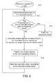
- FIG. 6 illustrates a booting method in a low-temperature environment, which is executed in the electronic apparatus 800 in FIG. 5 .
- each electronic device includes a hard disk driver 900a, 900b...900N, and each hard disk driver 900a/900b/.../900N has a fluid dynamic bearing.
- a controller 140 can be a keyboard controller or an EC.
- the architecture of this embodiment is substantially the same as that of the second embodiment, and is characterized by combining the heating circuit into the electronic apparatus 800.
- the electronic apparatus 800 includes a heating circuit, a power supplier 110, a controller 140, a central processing unit (CPU) 810, a bridge chip 820, a system memory 840, a plurality of hard disk drivers 900a, 900b...900N, a display interface 860, a display module 870, and a read only memory (ROM) 880.
- the heating circuit includes a plurality of heaters (120a, 120b..., 120N), and a plurality of thermal sensors (130a, 130b... 130N).
- the controller 140 is an EC or a keyboard controller. As the elements are substantially the same as those in a common laptop computer, only different elements are described hereafter.
- the electronic apparatus is in a shutdown mode (S5), a dormant mode (S4), or a sleep mode (S3) of an Advanced Configuration and Power Interface (ACPI).
- S5 a shutdown mode
- S4 a dormant mode
- S3 a sleep mode of an Advanced Configuration and Power Interface
- the controller 140 obtains the temperatures (Td1, Td2,..., TdN) of the hard disk drivers (900a, 900b,..., 900N) through the thermal sensors (130a, 130b,..., 130N) (S11).
- the request of the user includes an event of requiring the electronic apparatus 800 to enter an operation mode (for example, an operation mode (S0/G0) of the ACPI).
- the event of the present invention may be an event generated by software or firmware or a signal generated by hardware.
- the controller 140 After obtaining the temperatures (Td1, Td2,..., TdN) of all the hard disk drivers (900a, 900b,..., 900N) through the thermal sensors (130a, 130b,..., 130N), the controller 140 determines whether the temperatures of all the hard disk drivers reach a threshold value (S12).
- the controller 140 determines that the temperatures (Td1, Td2... TdN) of all the hard disk drivers 900a, 900b..., and 900N reach the threshold value Tth, the controller 140 enables the electronic apparatus 800 to enter the operation mode (S13). After the electronic apparatus 800 enters the operation mode, the hard disk drivers (900a, 900b... 900N) operate normally.
- the controller 140 determines that the temperatures (Td1, Td2,..., TdN) of at least two hard disk drivers (900a, 900b,..., 900N) do not reach the threshold value Tth, the controller 140 generates enable signals PWM1/PWM2/.../PWM N corresponding to the hard disk drivers 900a/900b/ .../900N having the temperatures (Td1, Td2,..., TdN) lower than the threshold value Tth (S14).
- the waveforms of the generated enable signals PWM1/PWM2/.../PWM N vary alternately.
- the controller 140 only generates the enable signals PWM1/PWM2/.../PWM N corresponding to the hard disk drivers 900a/900b/.../900N having the temperatures lower than the threshold value Tth.
- the controller 140 can also generate the enable signals PWM1/PWM2/.../PWM N corresponding to the hard disk drivers 900a/900b/.../900N having the temperatures Td1, Td2... TdN higher than or equal to the threshold value Tth.
- the alternately varying waveforms described in this embodiment may be totally non-overlapped waveforms, alternately switched waveforms, or partially overlapped waveforms of the enable signals PWM1/PWM2/.../PWM N.
- the controller 140 when only Td1, Td2, TdN among the temperatures of all the hard disk drivers obtained by the controller 140 are lower than the threshold value Tth, the controller 140 only generates the enable signals PWM1, PWM2, PWM N.
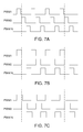
- the waveforms of the enable signals PWM1, PWM2, PWM N are totally non-overlapped, as illustrated in FIG. 7A .
- the waveforms of the enable signals PWM1, PWM2, PWM N are alternately switched, as illustrated in FIG. 7B .
- the waveforms of the enable signals PWM1, PWM2, PWM N are partially overlapped, as illustrated in FIG. 7C .
- the controller 140 transfers the enable signals to the corresponding heaters (S15), in which each enable signal PWM1/PWM2/.../PWM N is transferred to at least one heater 120a/120b/.../120N. For example, if the controller 140 only generates the enable signals PWM1, PWM2, PWM N, the controller 140 respectively transfers the enable signals PWM1, PWM2, PWM N to the corresponding heaters 120a, 120b, 120N.
- each heater 120a/120b/.../120N After the heater 120a/120b/.../120N receives the enable signal PWM1/PWM2/.../PWM N generated by the controller 140, each heater 120a/120b/.../120N heats the hard disk driver 900a/900b/.../900N according to the received enable signal PWM1/PWM2/.../PWM N (S16). For example, if only the enable signals PWM1, PWM2, PWM N are transferred to the corresponding heaters 120a, 120b, 120N, the heaters 120a, 120b, 120N heat the hard disk drivers 900a, 900b, 900N according to the enable signals PWM1, PWM2, PWM N.
- each enable signal PWM1/PWM2/.../PWM N is transferred to at least one heater 120a/120b/.../120N.
- each enable signal PWM1/PWM2/.../PWM N is transferred to all the heaters 120a/120b/.../120N on the same hard disk driver 900a/900b/.../900N.
- Steps S11-S16 are repeated. Till the controller 140 determines that the temperatures (Td1, Td2... TdN) of all the hard disk drivers 900a, 900b..., 900N reach the threshold value Tth, the controller 140 enables the electronic apparatus 800 to enter the operation modeS0/G0 of the ACPI (S13).
- the temperatures of the hard disk drivers 900a/900b/.../900N are first confirmed, and after it is confirmed that the temperatures of the hard disk drivers 900a/900b/.../900N exceed the threshold value, the electronic apparatus 800 is enabled to enter the operation mode.
- the hard disk drivers 900a/900b/.../900N are prevented from operating in a low-temperature state.
- the hard disk drivers 900a/900b/.../900N are heated simultaneously, such that at least one enable signal and other enable signals are at least partially non-overlapped, and thus the heaters can achieve an optimal heating efficiency, and an instantaneous total electric power of the heater will not be excessively high.
Landscapes
- Engineering & Computer Science (AREA)
- Remote Sensing (AREA)
- Physics & Mathematics (AREA)
- General Physics & Mathematics (AREA)
- Automation & Control Theory (AREA)
- Control Of Temperature (AREA)
- Control Of Resistance Heating (AREA)
- Electronic Switches (AREA)
Abstract
Description
- The present invention relates to operate an electronic device in a low-temperature environment, and more particularly, to a heating circuit and a method for entering an operation mode in a low-temperature environment.
- In a low-temperature environment, for example, an environment at a temperature lower than -20°C, a part of electronic components in an electronic apparatus cannot operate normally, and even be damaged in operation. Especially for a fluid dynamic bearing in a common hard disk driver, in the low-temperature environment, a viscous liquid film in the fluid dynamic bearing is likely to be solidified. When the viscous liquid film in the fluid dynamic bearings is solidified, if the disk of the hard disk driver rotates, the disk may be damaged, and data stored in the hard disk driver is damaged.
- A rugged electronic apparatus, such as a rugged laptop computer, has one or more built-in heaters for heating the hard disk driver or the battery in the rugged electronic apparatus. The purpose of heating the hard disk driver or the battery is to maintain the viscous liquid film or the electrolyte in the fluid dynamic bearing in a liquid state without being solidified. Before booting up, such an electronic apparatus allows the user to turn on the heaters manually, so as to heat the aforementioned electronic components and then switch the electronic apparatus to boot up after a period of heating.
- Theoretically speaking, heating the hard disk drivers by multiple heaters simultaneously, the electronic apparatus can boot up as soon as possible. In fact, the average electric power obtained by each heater from the power supplier is reduced when the number of the heaters is increased; therefore, a heating efficiency of each hard disk driver is reduced.
- The present invention is directed to a heating circuit for hard disk drivers, an electronic apparatus, and a method for entering an operation mode in a low-temperature environment, to solve the problems mentioned above.
- The present invention provides a heating circuit, applicable in a situation that plural electronic devices are not activated. The heating circuit includes a plurality of thermal sensors, a controller, and a plurality of heaters. The thermal sensors are provided for respectively detecting a temperature of each electronic device. The controller is provided for obtaining the temperatures of all the electronic devices through the thermal sensors, determining whether the temperatures of all the electronic devices reach a threshold value, and generating a plurality of enable signals when the temperatures of at least two electronic devices are lower than the threshold value. The waveforms of the enable signals vary alternately. The heaters are provided for respectively receiving one of the enable signals, and heating at least one of the electronic devices according to the received enable signal.
- The present invention further provides a method for entering an operation mode in a low-temperature environment, applicable in a situation that plural electronic devices in an electronic apparatus are not activated. By performing the method, an electronic apparatus obtains a temperature of each electronic device after receiving a request of a user, wherein the request includes an event of requiring the electronic apparatus to enter the operation mode. Then, the electronic apparatus determines whether the temperatures of all the electronic devices reach a threshold value. If the temperatures of at least two electronic devices do not reach the threshold value, the electronic apparatus generates a plurality of enable signals corresponding to the electronic devices having the temperature lower than the threshold value, wherein waveforms of the enable signals vary alternately. Then the electronic apparatus transfers the enable signals to the corresponding heaters, in which each enable signal is transferred to at least one of the heaters, so as to heat one of the electronic devices by each heater according to the received enable signal.
- The present invention will become more fully understood from the detailed description given herein below for illustration only, and thus are not limitative of the present invention, and wherein:
-
FIG. 1 is a block diagram of a heating circuit according to a first embodiment of the present invention; -
FIGs. 2A, 2B, and 2C are waveform charts I, II, and III of enable signals according to the first embodiment of the present invention; -
FIG. 3 is a circuit diagram of the heater according to the first embodiment of the present invention; -
FIG. 4 is a circuit diagram of the heating circuit according to a second embodiment of the present invention; -
FIG. 5 is a circuit diagram of an electronic apparatus according to a third embodiment of the present invention; -
FIG. 6 is a flow chart of a third embodiment of the present invention; and -
FIGs. 7A, 7B, 7C are waveform charts I, II, and III of enable signals according to the third embodiment of the present invention. - Referring to
FIG. 1 , a heating circuit according to a first embodiment of the present invention illustrated. The heating circuit is applicable in a situation that plural electronic devices are not activated. The heating circuit obtains a power from apower supplier 110 to heat the plurality of electronic devices. In this embodiment, the electronic devices include twohard disk drivers hard disk driver heaters thermal sensors controller 140. - As illustrated in
FIG. 1 , thepower supplier 110 is for converting the voltage output of a source to a specific voltage and then output the specific voltage. Taking an IBM PC compatible computer as an example, the power provided by thepower supplier 110 is a direct current (DC), and a voltage of the DC is usually continuous DC of 12 V and 5 V. - As illustrated in
FIG. 1 , the twoheaters hard disk drivers hard disk drivers hard disk driver heaters 120a/120b. In this embodiment, only oneheater 120a/120b is disposed on eachhard disk driver 900a/900b. In fact, plural heaters may be disposed on one singlehard disk driver 900a/900b, to improve a heating effect of the singlehard disk driver 900a/900b. - As illustrated in
FIG. 1 , thethermal sensors hard disk drivers hard disk drivers hard disk drivers thermal sensors hard disk drivers thermal sensors hard disk drivers - As illustrated in
FIG. 1 , an example of thecontroller 140 is an embedded controller (EC) or a keyboard controller of a computer, and thecontroller 140 executes a program code, such that thecontroller 140 can receive the temperatures Td1, Td2 detected by thethermal sensors controller 140. - The
controller 140 obtains the temperatures Td1, Td2 of the hard disk drivers through thethermal sensors - When both the temperatures Td1, Td2 of the
hard disk drivers controller 140 respectively transfers a first enable signal PWM1 and a second enable signal PWM2 to the correspondingfirst heater 120a and the correspondingsecond heater 120b. Then, thefirst heater 120a and thesecond heater 120b respectively heat thehard disk driver - The
first heater 120a heats thehard disk driver 900a when the first enable signal PWM1 is at a high-voltage level, and stops heating thehard disk driver 900a when the first enable signal PWM1 is at a low-voltage level. Similar to the heating mode of thefirst heater 120a, thesecond heater 120b heats thehard disk driver 900b when the second enable signal PWM2 is at the high-voltage level, and stops heating thehard disk driver 900b when the second enable signal PWM2 is at the low-voltage level. - The first enable signal PWM1 and the second enable signal PWM2 can be pulse width modulation (PWM) signals, and the waveforms of the enable signals vary alternately. As illustrated in
FIG. 2A , the waveforms of the first enable signal PWM1 and the second enable signal PWM2 are totally non-overlapped. As illustrated inFIG. 2B , the waveforms of the first enable signal PWM1 and the second enable signal PWM2 are alternately switched. As illustrated inFIG. 2C , the waveforms of the first enable signal PWM1 and the second enable signal PWM2 are partially overlapped. - In this manner, an overload situation of the
power supplier 110 caused by heating thehard disk drivers heaters heaters power supplier 110 is close to, but does not exceeds, a maximal load of thepower supplier 110. - Referring to
FIG. 3 , a structure of thefirst heater 120a is illustrated. Thefirst heater 120a at least includes athermoelectric element 121 and aswitch 122. When the first enable signal PWM1 is at the high-voltage level, thefirst heater 120a turns on theswitch 122, to enable thethermoelectric element 121 to heat thehard disk driver 900a. When the first enable signal PWM1 is at the low-voltage level, thefirst heater 120a turns off theswitch 122, to enable thethermoelectric element 121 to stop heating thehard disk driver 900a. In the same manner of thefirst heater 120a, thesecond heater 120b can also control whether to heat thehard disk driver 900b according to whether the second enable signal PWM2 is at the high-voltage level or low-voltage level. - Referring to
FIG. 4 , a heating circuit according to a second embodiment of the present invention is illustrated. The heating circuit is applicable in a situation that plural electronic devices are not activated. In this embodiment, the heating circuit is utilized to heat more than two electronic devices. An example is that the electronic devices includes plural hard disk drivers (900a, 900b...900N), and each hard disk driver (900a, 900b...900N) has a fluid dynamic bearing (not illustrated in the drawing). - In this embodiment, the heating circuit includes a plurality of heaters (120a, 120b..., 120N), a plurality of thermal sensors (130a, 130b... 130N), and a
controller 140. Each thermal sensor (130a, 130b... 130N) is provided for respectively detecting the temperature of one single hard disk driver (900a, 900b...900N), to obtain the temperatures (Td1, Td2... TdN) corresponding to the hard disk drivers (900a, 900b...900N). Thecontroller 140 is an EC or a keyboard controller. In this embodiment, the structures and the heating modes of the heaters (120a, 120b... 120N) are the same as those of thefirst heater 120a in the first embodiment. - The
controller 140 obtains the temperatures (Td1, Td2,..., TdN) of all the hard disk drivers (900a, 900b,..., 900N) through the thermal sensors (130a, 130b,..., 130N), and determines whether the temperatures (Td1, Td2...TdN) of the hard disk drivers reach a threshold value Tth. - When at least two of the temperatures (Td1, Td2,..., TdN) of the hard disk drivers are lower than the threshold value Tth, for example, Td1 and Td2 among the temperatures (Td1, Td2,..., TdN) are lower than the threshold value Tth, the
controller 140 generates corresponding enable signals (PWM1, PWM2) according to the temperatures (Td1, Td2) lower than the threshold value Tth. The waveforms of the enable signals PWM1, PWM2 vary alternately. Then, the enable signals PWM1, PWM2 are transferred to the correspondingheaters hard disk drivers - In this embodiment, the
controller 140 only generates the plurality of enable signals (PWM1, PWM2,..., PWM N) for heating the electronic devices having the temperatures (Td1, Td2,..., TdN) lower than the threshold value Tth, when the temperatures (Td1, Td2,..., TdN) of at least two electronic devices are lower than the threshold value Tth. In practice, thecontroller 140 can also generate other enable signals (PWM1, PWM2,..., PMW N) for heating the other electronic devices having the temperatures (Td1, Td2,..., TdN) higher than or equal to the threshold value Tth. - Furthermore, each enable signal (PWM1/PWM2/.../PMW N) is transferred to at least one heater (130a/130b/.../130N). For example, when only a signal heater (130a/130b/.../130N) is disposed on each hard disk driver (900a/900b/.../900N), each enable signals (PWM1/PWM2/.../PMW N) is transferred to one single heater (130a/130b/.../130N). If plural heaters (130a, 130b... 130N) are disposed on one hard disk driver, one single enable signal (PWM1/PWM2/.../PMW N) is transferred to all the heaters (130a, 130b... 130N) on the same hard disk driver (900a/900b/.../900N).
- Furthermore, the present invention provides an
electronic apparatus 800, which can be a laptop computer, a personal digital assistant (PDA), a portable navigation device (PND), or a tablet computer. As illustrated inFIG. 5 , theelectronic apparatus 800 in this embodiment is a laptop computer. The heating circuit of embodiments of the present invention is quipped within theelectronic apparatus 800, and is applicable in a situation that plural electronic devices of the electronic apparatus 800are not activated. Referring toFIG. 6 in combination,FIG. 6 illustrates a booting method in a low-temperature environment, which is executed in theelectronic apparatus 800 inFIG. 5 . In this embodiment, each electronic device includes ahard disk driver hard disk driver 900a/900b/.../900N has a fluid dynamic bearing. Acontroller 140 can be a keyboard controller or an EC. The architecture of this embodiment is substantially the same as that of the second embodiment, and is characterized by combining the heating circuit into theelectronic apparatus 800. - The
electronic apparatus 800 includes a heating circuit, apower supplier 110, acontroller 140, a central processing unit (CPU) 810, abridge chip 820, asystem memory 840, a plurality ofhard disk drivers display interface 860, adisplay module 870, and a read only memory (ROM) 880. The heating circuit includes a plurality of heaters (120a, 120b..., 120N), and a plurality of thermal sensors (130a, 130b... 130N). Thecontroller 140 is an EC or a keyboard controller. As the elements are substantially the same as those in a common laptop computer, only different elements are described hereafter. - First, in the situation that the electronic devices are not activated, the electronic apparatus is in a shutdown mode (S5), a dormant mode (S4), or a sleep mode (S3) of an Advanced Configuration and Power Interface (ACPI).
- After the
electronic apparatus 800 receives a request of a user, thecontroller 140 obtains the temperatures (Td1, Td2,..., TdN) of the hard disk drivers (900a, 900b,..., 900N) through the thermal sensors (130a, 130b,..., 130N) (S11). The request of the user includes an event of requiring theelectronic apparatus 800 to enter an operation mode (for example, an operation mode (S0/G0) of the ACPI). The event of the present invention may be an event generated by software or firmware or a signal generated by hardware. - After obtaining the temperatures (Td1, Td2,..., TdN) of all the hard disk drivers (900a, 900b,..., 900N) through the thermal sensors (130a, 130b,..., 130N), the
controller 140 determines whether the temperatures of all the hard disk drivers reach a threshold value (S12). - If the
controller 140 determines that the temperatures (Td1, Td2... TdN) of all thehard disk drivers controller 140 enables theelectronic apparatus 800 to enter the operation mode (S13). After theelectronic apparatus 800 enters the operation mode, the hard disk drivers (900a, 900b... 900N) operate normally. - If the
controller 140 determines that the temperatures (Td1, Td2,..., TdN) of at least two hard disk drivers (900a, 900b,..., 900N) do not reach the threshold value Tth, thecontroller 140 generates enable signals PWM1/PWM2/.../PWM N corresponding to thehard disk drivers 900a/900b/ .../900N having the temperatures (Td1, Td2,..., TdN) lower than the threshold value Tth (S14). The waveforms of the generated enable signals PWM1/PWM2/.../PWM N vary alternately. - In this embodiment, the
controller 140 only generates the enable signals PWM1/PWM2/.../PWM N corresponding to thehard disk drivers 900a/900b/.../900N having the temperatures lower than the threshold value Tth. In practice, thecontroller 140 can also generate the enable signals PWM1/PWM2/.../PWM N corresponding to thehard disk drivers 900a/900b/.../900N having the temperatures Td1, Td2... TdN higher than or equal to the threshold value Tth. - The alternately varying waveforms described in this embodiment may be totally non-overlapped waveforms, alternately switched waveforms, or partially overlapped waveforms of the enable signals PWM1/PWM2/.../PWM N.
- For example, when only Td1, Td2, TdN among the temperatures of all the hard disk drivers obtained by the
controller 140 are lower than the threshold value Tth, thecontroller 140 only generates the enable signals PWM1, PWM2, PWM N. The waveforms of the enable signals PWM1, PWM2, PWM N are totally non-overlapped, as illustrated inFIG. 7A . The waveforms of the enable signals PWM1, PWM2, PWM N are alternately switched, as illustrated inFIG. 7B . The waveforms of the enable signals PWM1, PWM2, PWM N are partially overlapped, as illustrated inFIG. 7C . - Next, the
controller 140 transfers the enable signals to the corresponding heaters (S15), in which each enable signal PWM1/PWM2/.../PWM N is transferred to at least oneheater 120a/120b/.../120N. For example, if thecontroller 140 only generates the enable signals PWM1, PWM2, PWM N, thecontroller 140 respectively transfers the enable signals PWM1, PWM2, PWM N to the correspondingheaters - After the
heater 120a/120b/.../120N receives the enable signal PWM1/PWM2/.../PWM N generated by thecontroller 140, eachheater 120a/120b/.../120N heats thehard disk driver 900a/900b/.../900N according to the received enable signal PWM1/PWM2/.../PWM N (S16). For example, if only the enable signals PWM1, PWM2, PWM N are transferred to the correspondingheaters heaters hard disk drivers - Furthermore, each enable signal PWM1/PWM2/.../PWM N is transferred to at least one
heater 120a/120b/.../120N. For example, when only onesingle heater 120a/120b/.../120N is disposed on eachhard disk driver 900a/900b/.../900N, on single enable signal PWM1/PWM2/.../PWM N is only transferred to thesingle heater 120a/120b/.../120N. Ifplural heaters 120a/120b/.../120N are disposed on onehard disk driver 900a/900b/.../900N, the single enable signal PWM1/PWM2/.../PWM N is transferred to all theheaters 120a/120b/.../120N on the samehard disk driver 900a/900b/.../900N. - After the
heater 120a/120b/.../120N heats thehard disk driver 120a/120b/.../120N for a preset time, Steps S11-S16 are repeated. Till thecontroller 140 determines that the temperatures (Td1, Td2... TdN) of all thehard disk drivers controller 140 enables theelectronic apparatus 800 to enter the operation modeS0/G0 of the ACPI (S13). - According to the embodiments of the present invention, before the
electronic apparatus 800 boots up, the temperatures of thehard disk drivers 900a/900b/.../900N are first confirmed, and after it is confirmed that the temperatures of thehard disk drivers 900a/900b/.../900N exceed the threshold value, theelectronic apparatus 800 is enabled to enter the operation mode. Thus, thehard disk drivers 900a/900b/.../900N are prevented from operating in a low-temperature state. In this embodiment, thehard disk drivers 900a/900b/.../900N are heated simultaneously, such that at least one enable signal and other enable signals are at least partially non-overlapped, and thus the heaters can achieve an optimal heating efficiency, and an instantaneous total electric power of the heater will not be excessively high. - While the present invention has been described by the way of example and in terms of the preferred embodiments, it is to be understood that the invention need not to be limited to the disclosed embodiments. On the contrary, it is intended to cover various modifications and similar arrangements included within the spirit and scope of the appended claims, the scope of which should be accorded the broadest interpretation so as to encompass all such modifications and similar structures.
Claims (14)
- A heating circuit, applicable in a situation that plural electronic devices are not activated, the heating circuit comprising:a plurality of thermal sensors, for respectively detecting a temperature of each electronic device;a controller, for obtaining the temperatures of all the electronic devices through the thermal sensors, determining whether the temperatures of all the electronic devices reach a threshold value, and generating a plurality of enable signals when the temperatures of at least two electronic devices are lower than the threshold value, wherein waveforms of the enable signals vary alternately; anda plurality of heaters, for respectively receiving one of the enable signals, and heating at least one of the electronic devices according to the received enable signal.
- The heating circuit as claimed in claim 1, wherein the controller is an embedded controller or a keyboard controller.
- The heating circuit as claimed in claim 1, wherein each enable signal is a pulse width modulation signal.
- The heating circuit as claimed in claim 1, wherein the waveforms of the enable signals are totally non-overlapped, alternately switched, or partially overlapped.
- The heating circuit as claimed in claim 1, wherein the electronic device comprises a hard disk driver, and the hard disk driver has a fluid dynamic bearing.
- The heating circuit as claimed in claim 1, wherein the controller generates the plurality of enable signals only for the electronic devices having the temperatures lower than the threshold value, when the temperatures of at least two electronic devices are lower than the threshold value.
- The heating circuit as claimed in claim 1, wherein each of the enable signals is transferred to at least one heater.
- The heating circuit as claimed in claim 1, wherein the heating circuit is quipped within an electronic apparatus and the situation that each electronic device is not activated comprises that the electronic apparatus is in a shutdown mode, a dormant mode, or a sleep mode of an Advanced Configuration and Power Interface.
- The heating circuit as claimed in claim 8, wherein after the controller determines that the temperatures of all the electronic devices reach the threshold value, the controller enables the electronic apparatus to enter an operation mode of the ACPI.
- A method for entering an operation mode in a low-temperature environment, applicable in a situation that plural electronic devices in an electronic apparatus are not activated, the method comprising:after receiving a request, obtaining a temperature of each electronic device, wherein the request comprises an event of requiring the electronic apparatus to enter the operation mode;determining whether the temperatures of all the electronic devices reach a threshold value;if the temperatures of at least two electronic devices do not reach the threshold value, generating a plurality of enable signals corresponding to the electronic devices having the temperature lower than the threshold value, wherein waveforms of the enable signals substantially vary alternately;respectively transferring the enable signals to a plurality of corresponding heaters, wherein each of the enable signals is transferred to at least one of the heaters; andheating at least one of the electronic devices by each heater according to the received enable signal.
- The method for entering an operation mode in a low-temperature environment as claimed in claim 10, wherein in the situation that the electronic devices are not activated, the electronic apparatus is in a shutdown mode, a dormant mode, or a sleep mode of an Advanced Configuration and Power Interface, and the operation mode is a mode of the Advanced Configuration and Power Interface.
- The method for entering an operation mode in a low-temperature environment as claimed in claim 10, wherein if the temperatures of all the electronic devices reach the threshold value, the electronic apparatus is enabled to enter the operation mode.
- The method for entering an operation mode in a low-temperature environment as claimed in claim 10, wherein the enable signal is a pulse width modulation signal.
- The method for entering an operation mode in a low-temperature environment as claimed in claim 10, wherein the waveforms of the enable signals are totally non-overlapped, alternately switched, or partially overlapped.
Applications Claiming Priority (1)
| Application Number | Priority Date | Filing Date | Title |
|---|---|---|---|
| CN201110072145.9A CN102681571B (en) | 2011-03-15 | 2011-03-15 | Heating circuit, electronic device and method for entering working mode in low temperature environment |
Publications (3)
| Publication Number | Publication Date |
|---|---|
| EP2511784A2 true EP2511784A2 (en) | 2012-10-17 |
| EP2511784A3 EP2511784A3 (en) | 2016-06-22 |
| EP2511784B1 EP2511784B1 (en) | 2017-09-06 |
Family
ID=45002646
Family Applications (1)
| Application Number | Title | Priority Date | Filing Date |
|---|---|---|---|
| EP11188048.0A Active EP2511784B1 (en) | 2011-03-15 | 2011-11-07 | Heating circuit and method for entering operation mode in low-temperature environment |
Country Status (3)
| Country | Link |
|---|---|
| US (1) | US9684319B2 (en) |
| EP (1) | EP2511784B1 (en) |
| CN (1) | CN102681571B (en) |
Families Citing this family (8)
| Publication number | Priority date | Publication date | Assignee | Title |
|---|---|---|---|---|
| US9658629B2 (en) | 2012-03-22 | 2017-05-23 | Seagate Technology Llc | Method and apparatus for controlling the temperature of components |
| CN104597942A (en) * | 2013-10-31 | 2015-05-06 | 鸿富锦精密工业(深圳)有限公司 | Temperature control circuit |
| CN106325443A (en) * | 2015-06-26 | 2017-01-11 | 神讯电脑(昆山)有限公司 | Notebook computer heating device |
| CN105573372B (en) * | 2015-12-22 | 2017-09-15 | 广东欧珀移动通信有限公司 | A kind of control method and device of intelligent terminal |
| CN109588783A (en) * | 2018-12-26 | 2019-04-09 | 深圳市太美亚电子科技有限公司 | A kind of the Novel heating method and electronic cigarette of electronic cigarette |
| CN112837715B (en) * | 2019-11-25 | 2023-03-21 | 神讯电脑(昆山)有限公司 | Mechanical hard disk heating device and heating method |
| US11937396B2 (en) * | 2022-01-14 | 2024-03-19 | Dell Products L.P. | Heater apparatus-integrated top cover for a computing device |
| US20250246210A1 (en) * | 2024-01-30 | 2025-07-31 | Dell Products L.P. | Information Handling System Drive System Having an Integrated Heating Solution |
Family Cites Families (46)
| Publication number | Priority date | Publication date | Assignee | Title |
|---|---|---|---|---|
| US3725768A (en) | 1971-06-07 | 1973-04-03 | Westinghouse Electric Corp | Current fed inverter circuit using the time sharing principle |
| US5105067A (en) * | 1989-09-08 | 1992-04-14 | Environwear, Inc. | Electronic control system and method for cold weather garment |
| US6009369A (en) * | 1991-10-31 | 1999-12-28 | Nartron Corporation | Voltage monitoring glow plug controller |
| US5818717A (en) * | 1993-06-02 | 1998-10-06 | Trintec Industries Inc. | Automated small volume production of instrument faces |
| JPH0879800A (en) * | 1994-09-06 | 1996-03-22 | Olympus Optical Co Ltd | Video image display device |
| TW502557B (en) | 1997-01-21 | 2002-09-11 | Lg Electronics Inc | Resonance type induction cooking apparatus for multi-output control |
| US6093916A (en) * | 1997-10-06 | 2000-07-25 | Canon Kabushiki Kaisha | Control device with first and second power control elements to control heater drive apparatus |
| US6169930B1 (en) * | 1998-04-17 | 2001-01-02 | International Business Machines Corporation | Method and apparatus for preventing cold temperature induced damage in a disk drive |
| US6212644B1 (en) * | 1998-09-10 | 2001-04-03 | Intel Corporation | Controlling temperatures in computers |
| US6127660A (en) * | 1998-12-31 | 2000-10-03 | Lucent Technologies, Inc. | Heated microcell base station |
| JP2001023106A (en) * | 1999-07-06 | 2001-01-26 | Fujitsu Ltd | Magnetic disk drive |
| JP3988338B2 (en) * | 1999-10-07 | 2007-10-10 | ウシオ電機株式会社 | Control device for light irradiation type rapid heat treatment equipment |
| EP1291741B1 (en) | 2000-04-14 | 2012-05-09 | Omron Corporation | Controller, temperature regulator, and heat treatment apparatus |
| US6735035B1 (en) * | 2000-11-20 | 2004-05-11 | International Business Machines Corporation | Method and apparatus for enabling cold temperature performance of a disk |
| JP2002245749A (en) * | 2001-02-21 | 2002-08-30 | Fujitsu Ltd | Disk device and information processing device |
| US20030088799A1 (en) * | 2001-11-05 | 2003-05-08 | Bodas Devadatta V. | Method and apparatus for regulation of electrical component temperature and power consumption rate through bus width reconfiguration |
| US7035031B2 (en) * | 2001-11-26 | 2006-04-25 | Samsung Electronics Co., Ltd. | Installation of heater into hard disk drive to improve reliability and performance at low temperature |
| US20070222295A1 (en) | 2002-09-05 | 2007-09-27 | Paul Wareham | System and method for power load management |
| US20050099766A1 (en) * | 2003-03-20 | 2005-05-12 | Fraley Peter D. | Transportable mass data storage system |
| US20040228023A1 (en) * | 2003-05-12 | 2004-11-18 | Keller Lee A. | Method and apparatus for heating a disk drive |
| GB0327453D0 (en) * | 2003-11-26 | 2003-12-31 | Motorola Inc | Apparatus and method of computer component heating |
| US20050216221A1 (en) * | 2004-03-29 | 2005-09-29 | Broyles Paul J Iii | Systems and methods for cooling storage devices |
| KR100621101B1 (en) * | 2004-04-08 | 2006-09-13 | 삼성전자주식회사 | Electronic device and control method |
| US7119978B2 (en) * | 2004-06-02 | 2006-10-10 | Seagate Technology Llc | Condensation compensation in a motion control system |
| JP2006092645A (en) * | 2004-09-24 | 2006-04-06 | Hitachi Global Storage Technologies Netherlands Bv | Disk drive device |
| CN1782945A (en) * | 2004-11-29 | 2006-06-07 | 纬创资通股份有限公司 | Heating device and method for computer system |
| CN1831694B (en) * | 2005-03-11 | 2010-06-23 | 佛山市顺德区顺达电脑厂有限公司 | Temp-control heating device for hydraulic bearing hard disk and its hard disk and control method |
| JP4692117B2 (en) * | 2005-07-15 | 2011-06-01 | 船井電機株式会社 | Information recording / reproducing device |
| EP1938328A4 (en) * | 2005-09-23 | 2008-12-03 | Toronto Microelectronics Inc | A data storage device and method |
| US7523338B2 (en) * | 2005-10-13 | 2009-04-21 | Research In Motion Limited | Apparatus and method to support USB enumeration of a bus powered handheld device |
| US20070165322A1 (en) * | 2005-12-30 | 2007-07-19 | Samsung Electronics Co., Ltd. | Method and apparatus regulating saturation water vapor pressure in a hard disk drive |
| JP2007249660A (en) * | 2006-03-16 | 2007-09-27 | Toshiba Corp | Information processing apparatus and system state control method |
| JP2008041118A (en) * | 2006-08-01 | 2008-02-21 | Denso Corp | Storage device and in-vehicle navigation system |
| JP2008075689A (en) * | 2006-09-19 | 2008-04-03 | Nissan Motor Co Ltd | Transmission control device of continuously variable transmission |
| JP3128149U (en) * | 2006-10-14 | 2006-12-28 | 船井電機株式会社 | Electronic device with built-in hard disk drive |
| CN101311899B (en) * | 2007-05-25 | 2010-10-27 | 佛山市顺德区顺达电脑厂有限公司 | Preheating control system and control method of information processing device |
| WO2009060506A1 (en) * | 2007-11-05 | 2009-05-14 | Fujitsu Limited | Storage medium driving device and method for controlling temperature of ramp member for storage medium driving device |
| TWM341238U (en) | 2008-01-18 | 2008-09-21 | Kumtek Internat Co Ltd | Heating device |
| US7609473B1 (en) * | 2008-05-13 | 2009-10-27 | Hitachi Global Storage Technologies Netherlands, B.V. | Dissipation of liquid droplets in a magnetic disk drive |
| US8095332B2 (en) * | 2008-09-10 | 2012-01-10 | Getac Technology Corporation | Method for pre-heating hard disk drive of computer device |
| US8200993B2 (en) * | 2008-09-18 | 2012-06-12 | Mitac Technology Corp. | Method for activating a computer system in a low temperature environment |
| US8176308B2 (en) * | 2008-09-18 | 2012-05-08 | Getac Technology Corporation | Method for activating a computer system in a low temperature environment |
| US8251580B2 (en) * | 2008-11-06 | 2012-08-28 | Mitac Technology Corp. | Apparatus and method for protecting overheated hard drive |
| DE102008043866B4 (en) | 2008-11-19 | 2016-01-14 | Getac Technology Corp. | A method of preheating the hard disk drive of a computer device |
| GB2466273B (en) * | 2008-12-18 | 2013-01-09 | Gm Global Tech Operations Inc | A method for controlling glow plugs in a diesel engine particularly for motor-vehicles |
| EP2224124A1 (en) * | 2009-02-27 | 2010-09-01 | Robert Bosch GmbH | A glow plug controller for vehicles |
-
2011
- 2011-03-15 CN CN201110072145.9A patent/CN102681571B/en active Active
- 2011-11-04 US US13/290,013 patent/US9684319B2/en active Active
- 2011-11-07 EP EP11188048.0A patent/EP2511784B1/en active Active
Non-Patent Citations (1)
| Title |
|---|
| None |
Also Published As
| Publication number | Publication date |
|---|---|
| CN102681571B (en) | 2015-02-04 |
| EP2511784B1 (en) | 2017-09-06 |
| CN102681571A (en) | 2012-09-19 |
| US9684319B2 (en) | 2017-06-20 |
| EP2511784A3 (en) | 2016-06-22 |
| US20120168417A1 (en) | 2012-07-05 |
Similar Documents
| Publication | Publication Date | Title |
|---|---|---|
| EP2511784B1 (en) | Heating circuit and method for entering operation mode in low-temperature environment | |
| US9952645B2 (en) | Firmware update and power system thereof | |
| US8462499B2 (en) | Information processing apparatus | |
| US7791301B2 (en) | Apparatus and method for fan auto-detection | |
| US7904734B1 (en) | Increasing mean time between failures for power supplies | |
| US10164457B2 (en) | Charging method and apparatus | |
| US9086862B2 (en) | Apparatus and method of protecting electronic apparatus using a temperature-power table for an electronic component under different system and environmental temperatures | |
| US8564248B2 (en) | Computer system mounted with battery pack for performing system control based on characteristics of the battery pack and system main body thereof | |
| US10651734B2 (en) | System and method for robust body braking control to suppress transient voltage overshoot | |
| US9923368B2 (en) | Electronic apparatus and driving control method thereof | |
| CN103064493B (en) | Electronic installation and preheat method and preheating apparatus | |
| CN106415984A (en) | Power supply device and image forming apparatus including such power supply device | |
| US10871813B2 (en) | Temperature increasing device and temperature increasing method | |
| US9134775B2 (en) | Controlling a current drawn from an adapter by a computer system | |
| CN116404307A (en) | Battery pack heating circuit control method and device, storage medium and computer equipment | |
| US8640968B2 (en) | Temperature gain control device and method thereof | |
| JP4876135B2 (en) | Electronics | |
| US10409344B2 (en) | Electronic device having temperature management function | |
| JP5787620B2 (en) | Electronic device, control method therefor, and program | |
| JP2018196295A (en) | Controller, power storage system and program | |
| US20140089695A1 (en) | Energy-saving device | |
| JP7765548B2 (en) | Power supply circuit, electronic device and control method | |
| US20260118932A1 (en) | Information processing apparatus and control method | |
| CN102681639A (en) | Power supply system and method for central processing unit | |
| CN116878683A (en) | Method for detecting internal temperature of battery and battery temperature detection circuit |
Legal Events
| Date | Code | Title | Description |
|---|---|---|---|
| PUAI | Public reference made under article 153(3) epc to a published international application that has entered the european phase |
Free format text: ORIGINAL CODE: 0009012 |
|
| AK | Designated contracting states |
Kind code of ref document: A2 Designated state(s): AL AT BE BG CH CY CZ DE DK EE ES FI FR GB GR HR HU IE IS IT LI LT LU LV MC MK MT NL NO PL PT RO RS SE SI SK SM TR |
|
| AX | Request for extension of the european patent |
Extension state: BA ME |
|
| PUAL | Search report despatched |
Free format text: ORIGINAL CODE: 0009013 |
|
| AK | Designated contracting states |
Kind code of ref document: A3 Designated state(s): AL AT BE BG CH CY CZ DE DK EE ES FI FR GB GR HR HU IE IS IT LI LT LU LV MC MK MT NL NO PL PT RO RS SE SI SK SM TR |
|
| AX | Request for extension of the european patent |
Extension state: BA ME |
|
| RIC1 | Information provided on ipc code assigned before grant |
Ipc: G11B 33/14 20060101ALI20160517BHEP Ipc: G05D 23/19 20060101AFI20160517BHEP |
|
| STAA | Information on the status of an ep patent application or granted ep patent |
Free format text: STATUS: REQUEST FOR EXAMINATION WAS MADE |
|
| 17P | Request for examination filed |
Effective date: 20161221 |
|
| RBV | Designated contracting states (corrected) |
Designated state(s): AL AT BE BG CH CY CZ DE DK EE ES FI FR GB GR HR HU IE IS IT LI LT LU LV MC MK MT NL NO PL PT RO RS SE SI SK SM TR |
|
| GRAP | Despatch of communication of intention to grant a patent |
Free format text: ORIGINAL CODE: EPIDOSNIGR1 |
|
| STAA | Information on the status of an ep patent application or granted ep patent |
Free format text: STATUS: GRANT OF PATENT IS INTENDED |
|
| RIC1 | Information provided on ipc code assigned before grant |
Ipc: G05D 23/19 20060101AFI20170214BHEP Ipc: G11B 33/14 20060101ALI20170214BHEP |
|
| INTG | Intention to grant announced |
Effective date: 20170321 |
|
| GRAS | Grant fee paid |
Free format text: ORIGINAL CODE: EPIDOSNIGR3 |
|
| GRAA | (expected) grant |
Free format text: ORIGINAL CODE: 0009210 |
|
| STAA | Information on the status of an ep patent application or granted ep patent |
Free format text: STATUS: THE PATENT HAS BEEN GRANTED |
|
| AK | Designated contracting states |
Kind code of ref document: B1 Designated state(s): AL AT BE BG CH CY CZ DE DK EE ES FI FR GB GR HR HU IE IS IT LI LT LU LV MC MK MT NL NO PL PT RO RS SE SI SK SM TR |
|
| REG | Reference to a national code |
Ref country code: GB Ref legal event code: FG4D |
|
| REG | Reference to a national code |
Ref country code: CH Ref legal event code: EP Ref country code: AT Ref legal event code: REF Ref document number: 926527 Country of ref document: AT Kind code of ref document: T Effective date: 20170915 |
|
| REG | Reference to a national code |
Ref country code: IE Ref legal event code: FG4D |
|
| REG | Reference to a national code |
Ref country code: DE Ref legal event code: R096 Ref document number: 602011041253 Country of ref document: DE |
|
| REG | Reference to a national code |
Ref country code: FR Ref legal event code: PLFP Year of fee payment: 7 |
|
| REG | Reference to a national code |
Ref country code: NL Ref legal event code: MP Effective date: 20170906 |
|
| REG | Reference to a national code |
Ref country code: LT Ref legal event code: MG4D |
|
| PG25 | Lapsed in a contracting state [announced via postgrant information from national office to epo] |
Ref country code: SE Free format text: LAPSE BECAUSE OF FAILURE TO SUBMIT A TRANSLATION OF THE DESCRIPTION OR TO PAY THE FEE WITHIN THE PRESCRIBED TIME-LIMIT Effective date: 20170906 Ref country code: LT Free format text: LAPSE BECAUSE OF FAILURE TO SUBMIT A TRANSLATION OF THE DESCRIPTION OR TO PAY THE FEE WITHIN THE PRESCRIBED TIME-LIMIT Effective date: 20170906 Ref country code: NO Free format text: LAPSE BECAUSE OF FAILURE TO SUBMIT A TRANSLATION OF THE DESCRIPTION OR TO PAY THE FEE WITHIN THE PRESCRIBED TIME-LIMIT Effective date: 20171206 Ref country code: FI Free format text: LAPSE BECAUSE OF FAILURE TO SUBMIT A TRANSLATION OF THE DESCRIPTION OR TO PAY THE FEE WITHIN THE PRESCRIBED TIME-LIMIT Effective date: 20170906 Ref country code: HR Free format text: LAPSE BECAUSE OF FAILURE TO SUBMIT A TRANSLATION OF THE DESCRIPTION OR TO PAY THE FEE WITHIN THE PRESCRIBED TIME-LIMIT Effective date: 20170906 |
|
| PGFP | Annual fee paid to national office [announced via postgrant information from national office to epo] |
Ref country code: FR Payment date: 20171124 Year of fee payment: 7 |
|
| REG | Reference to a national code |
Ref country code: AT Ref legal event code: MK05 Ref document number: 926527 Country of ref document: AT Kind code of ref document: T Effective date: 20170906 |
|
| PG25 | Lapsed in a contracting state [announced via postgrant information from national office to epo] |
Ref country code: LV Free format text: LAPSE BECAUSE OF FAILURE TO SUBMIT A TRANSLATION OF THE DESCRIPTION OR TO PAY THE FEE WITHIN THE PRESCRIBED TIME-LIMIT Effective date: 20170906 Ref country code: RS Free format text: LAPSE BECAUSE OF FAILURE TO SUBMIT A TRANSLATION OF THE DESCRIPTION OR TO PAY THE FEE WITHIN THE PRESCRIBED TIME-LIMIT Effective date: 20170906 Ref country code: ES Free format text: LAPSE BECAUSE OF FAILURE TO SUBMIT A TRANSLATION OF THE DESCRIPTION OR TO PAY THE FEE WITHIN THE PRESCRIBED TIME-LIMIT Effective date: 20170906 Ref country code: GR Free format text: LAPSE BECAUSE OF FAILURE TO SUBMIT A TRANSLATION OF THE DESCRIPTION OR TO PAY THE FEE WITHIN THE PRESCRIBED TIME-LIMIT Effective date: 20171207 Ref country code: BG Free format text: LAPSE BECAUSE OF FAILURE TO SUBMIT A TRANSLATION OF THE DESCRIPTION OR TO PAY THE FEE WITHIN THE PRESCRIBED TIME-LIMIT Effective date: 20171206 |
|
| PG25 | Lapsed in a contracting state [announced via postgrant information from national office to epo] |
Ref country code: NL Free format text: LAPSE BECAUSE OF FAILURE TO SUBMIT A TRANSLATION OF THE DESCRIPTION OR TO PAY THE FEE WITHIN THE PRESCRIBED TIME-LIMIT Effective date: 20170906 |
|
| PG25 | Lapsed in a contracting state [announced via postgrant information from national office to epo] |
Ref country code: RO Free format text: LAPSE BECAUSE OF FAILURE TO SUBMIT A TRANSLATION OF THE DESCRIPTION OR TO PAY THE FEE WITHIN THE PRESCRIBED TIME-LIMIT Effective date: 20170906 Ref country code: PL Free format text: LAPSE BECAUSE OF FAILURE TO SUBMIT A TRANSLATION OF THE DESCRIPTION OR TO PAY THE FEE WITHIN THE PRESCRIBED TIME-LIMIT Effective date: 20170906 Ref country code: CZ Free format text: LAPSE BECAUSE OF FAILURE TO SUBMIT A TRANSLATION OF THE DESCRIPTION OR TO PAY THE FEE WITHIN THE PRESCRIBED TIME-LIMIT Effective date: 20170906 |
|
| PG25 | Lapsed in a contracting state [announced via postgrant information from national office to epo] |
Ref country code: SK Free format text: LAPSE BECAUSE OF FAILURE TO SUBMIT A TRANSLATION OF THE DESCRIPTION OR TO PAY THE FEE WITHIN THE PRESCRIBED TIME-LIMIT Effective date: 20170906 Ref country code: SM Free format text: LAPSE BECAUSE OF FAILURE TO SUBMIT A TRANSLATION OF THE DESCRIPTION OR TO PAY THE FEE WITHIN THE PRESCRIBED TIME-LIMIT Effective date: 20170906 Ref country code: IS Free format text: LAPSE BECAUSE OF FAILURE TO SUBMIT A TRANSLATION OF THE DESCRIPTION OR TO PAY THE FEE WITHIN THE PRESCRIBED TIME-LIMIT Effective date: 20180106 Ref country code: EE Free format text: LAPSE BECAUSE OF FAILURE TO SUBMIT A TRANSLATION OF THE DESCRIPTION OR TO PAY THE FEE WITHIN THE PRESCRIBED TIME-LIMIT Effective date: 20170906 Ref country code: AT Free format text: LAPSE BECAUSE OF FAILURE TO SUBMIT A TRANSLATION OF THE DESCRIPTION OR TO PAY THE FEE WITHIN THE PRESCRIBED TIME-LIMIT Effective date: 20170906 |
|
| PGFP | Annual fee paid to national office [announced via postgrant information from national office to epo] |
Ref country code: IT Payment date: 20171222 Year of fee payment: 7 |
|
| REG | Reference to a national code |
Ref country code: DE Ref legal event code: R097 Ref document number: 602011041253 Country of ref document: DE |
|
| PG25 | Lapsed in a contracting state [announced via postgrant information from national office to epo] |
Ref country code: MC Free format text: LAPSE BECAUSE OF FAILURE TO SUBMIT A TRANSLATION OF THE DESCRIPTION OR TO PAY THE FEE WITHIN THE PRESCRIBED TIME-LIMIT Effective date: 20170906 |
|
| PLBE | No opposition filed within time limit |
Free format text: ORIGINAL CODE: 0009261 |
|
| STAA | Information on the status of an ep patent application or granted ep patent |
Free format text: STATUS: NO OPPOSITION FILED WITHIN TIME LIMIT |
|
| PG25 | Lapsed in a contracting state [announced via postgrant information from national office to epo] |
Ref country code: DK Free format text: LAPSE BECAUSE OF FAILURE TO SUBMIT A TRANSLATION OF THE DESCRIPTION OR TO PAY THE FEE WITHIN THE PRESCRIBED TIME-LIMIT Effective date: 20170906 Ref country code: CH Free format text: LAPSE BECAUSE OF NON-PAYMENT OF DUE FEES Effective date: 20171130 Ref country code: LI Free format text: LAPSE BECAUSE OF NON-PAYMENT OF DUE FEES Effective date: 20171130 |
|
| 26N | No opposition filed |
Effective date: 20180607 |
|
| PG25 | Lapsed in a contracting state [announced via postgrant information from national office to epo] |
Ref country code: LU Free format text: LAPSE BECAUSE OF NON-PAYMENT OF DUE FEES Effective date: 20171107 Ref country code: SI Free format text: LAPSE BECAUSE OF FAILURE TO SUBMIT A TRANSLATION OF THE DESCRIPTION OR TO PAY THE FEE WITHIN THE PRESCRIBED TIME-LIMIT Effective date: 20170906 |
|
| REG | Reference to a national code |
Ref country code: BE Ref legal event code: MM Effective date: 20171130 |
|
| REG | Reference to a national code |
Ref country code: IE Ref legal event code: MM4A |
|
| PG25 | Lapsed in a contracting state [announced via postgrant information from national office to epo] |
Ref country code: MT Free format text: LAPSE BECAUSE OF NON-PAYMENT OF DUE FEES Effective date: 20171107 |
|
| PG25 | Lapsed in a contracting state [announced via postgrant information from national office to epo] |
Ref country code: IE Free format text: LAPSE BECAUSE OF NON-PAYMENT OF DUE FEES Effective date: 20171107 |
|
| PG25 | Lapsed in a contracting state [announced via postgrant information from national office to epo] |
Ref country code: BE Free format text: LAPSE BECAUSE OF NON-PAYMENT OF DUE FEES Effective date: 20171130 |
|
| PG25 | Lapsed in a contracting state [announced via postgrant information from national office to epo] |
Ref country code: HU Free format text: LAPSE BECAUSE OF FAILURE TO SUBMIT A TRANSLATION OF THE DESCRIPTION OR TO PAY THE FEE WITHIN THE PRESCRIBED TIME-LIMIT; INVALID AB INITIO Effective date: 20111107 |
|
| PG25 | Lapsed in a contracting state [announced via postgrant information from national office to epo] |
Ref country code: IT Free format text: LAPSE BECAUSE OF NON-PAYMENT OF DUE FEES Effective date: 20181107 Ref country code: FR Free format text: LAPSE BECAUSE OF NON-PAYMENT OF DUE FEES Effective date: 20181130 Ref country code: CY Free format text: LAPSE BECAUSE OF NON-PAYMENT OF DUE FEES Effective date: 20170906 |
|
| PG25 | Lapsed in a contracting state [announced via postgrant information from national office to epo] |
Ref country code: MK Free format text: LAPSE BECAUSE OF FAILURE TO SUBMIT A TRANSLATION OF THE DESCRIPTION OR TO PAY THE FEE WITHIN THE PRESCRIBED TIME-LIMIT Effective date: 20170906 |
|
| PG25 | Lapsed in a contracting state [announced via postgrant information from national office to epo] |
Ref country code: TR Free format text: LAPSE BECAUSE OF FAILURE TO SUBMIT A TRANSLATION OF THE DESCRIPTION OR TO PAY THE FEE WITHIN THE PRESCRIBED TIME-LIMIT Effective date: 20170906 |
|
| PG25 | Lapsed in a contracting state [announced via postgrant information from national office to epo] |
Ref country code: PT Free format text: LAPSE BECAUSE OF FAILURE TO SUBMIT A TRANSLATION OF THE DESCRIPTION OR TO PAY THE FEE WITHIN THE PRESCRIBED TIME-LIMIT Effective date: 20170906 |
|
| PG25 | Lapsed in a contracting state [announced via postgrant information from national office to epo] |
Ref country code: AL Free format text: LAPSE BECAUSE OF FAILURE TO SUBMIT A TRANSLATION OF THE DESCRIPTION OR TO PAY THE FEE WITHIN THE PRESCRIBED TIME-LIMIT Effective date: 20170906 |
|
| PGFP | Annual fee paid to national office [announced via postgrant information from national office to epo] |
Ref country code: GB Payment date: 20221123 Year of fee payment: 12 |
|
| GBPC | Gb: european patent ceased through non-payment of renewal fee |
Effective date: 20231107 |
|
| PG25 | Lapsed in a contracting state [announced via postgrant information from national office to epo] |
Ref country code: GB Free format text: LAPSE BECAUSE OF NON-PAYMENT OF DUE FEES Effective date: 20231107 |
|
| PG25 | Lapsed in a contracting state [announced via postgrant information from national office to epo] |
Ref country code: GB Free format text: LAPSE BECAUSE OF NON-PAYMENT OF DUE FEES Effective date: 20231107 |
|
| PGFP | Annual fee paid to national office [announced via postgrant information from national office to epo] |
Ref country code: DE Payment date: 20251106 Year of fee payment: 15 |