EP2511616A1 - Repartiteur de cout de chauffage - Google Patents
Repartiteur de cout de chauffage Download PDFInfo
- Publication number
- EP2511616A1 EP2511616A1 EP11305446A EP11305446A EP2511616A1 EP 2511616 A1 EP2511616 A1 EP 2511616A1 EP 11305446 A EP11305446 A EP 11305446A EP 11305446 A EP11305446 A EP 11305446A EP 2511616 A1 EP2511616 A1 EP 2511616A1
- Authority
- EP
- European Patent Office
- Prior art keywords
- temperature
- heating element
- temperature sensor
- measuring
- electronic card
- Prior art date
- Legal status (The legal status is an assumption and is not a legal conclusion. Google has not performed a legal analysis and makes no representation as to the accuracy of the status listed.)
- Granted
Links
Images



Classifications
-
- G—PHYSICS
- G01—MEASURING; TESTING
- G01K—MEASURING TEMPERATURE; MEASURING QUANTITY OF HEAT; THERMALLY-SENSITIVE ELEMENTS NOT OTHERWISE PROVIDED FOR
- G01K17/00—Measuring quantity of heat
- G01K17/06—Measuring quantity of heat conveyed by flowing media, e.g. in heating systems e.g. the quantity of heat in a transporting medium, delivered to or consumed in an expenditure device
- G01K17/08—Measuring quantity of heat conveyed by flowing media, e.g. in heating systems e.g. the quantity of heat in a transporting medium, delivered to or consumed in an expenditure device based upon measurement of temperature difference or of a temperature
-
- G—PHYSICS
- G01—MEASURING; TESTING
- G01K—MEASURING TEMPERATURE; MEASURING QUANTITY OF HEAT; THERMALLY-SENSITIVE ELEMENTS NOT OTHERWISE PROVIDED FOR
- G01K17/00—Measuring quantity of heat
- G01K17/06—Measuring quantity of heat conveyed by flowing media, e.g. in heating systems e.g. the quantity of heat in a transporting medium, delivered to or consumed in an expenditure device
-
- F—MECHANICAL ENGINEERING; LIGHTING; HEATING; WEAPONS; BLASTING
- F24—HEATING; RANGES; VENTILATING
- F24D—DOMESTIC- OR SPACE-HEATING SYSTEMS, e.g. CENTRAL HEATING SYSTEMS; DOMESTIC HOT-WATER SUPPLY SYSTEMS; ELEMENTS OR COMPONENTS THEREFOR
- F24D19/00—Details
- F24D19/10—Arrangement or mounting of control or safety devices
-
- G—PHYSICS
- G01—MEASURING; TESTING
- G01K—MEASURING TEMPERATURE; MEASURING QUANTITY OF HEAT; THERMALLY-SENSITIVE ELEMENTS NOT OTHERWISE PROVIDED FOR
- G01K1/00—Details of thermometers not specially adapted for particular types of thermometer
- G01K1/14—Supports; Fastening devices; Arrangements for mounting thermometers in particular locations
-
- G—PHYSICS
- G06—COMPUTING OR CALCULATING; COUNTING
- G06Q—INFORMATION AND COMMUNICATION TECHNOLOGY [ICT] SPECIALLY ADAPTED FOR ADMINISTRATIVE, COMMERCIAL, FINANCIAL, MANAGERIAL OR SUPERVISORY PURPOSES; SYSTEMS OR METHODS SPECIALLY ADAPTED FOR ADMINISTRATIVE, COMMERCIAL, FINANCIAL, MANAGERIAL OR SUPERVISORY PURPOSES, NOT OTHERWISE PROVIDED FOR
- G06Q50/00—Information and communication technology [ICT] specially adapted for implementation of business processes of specific business sectors, e.g. utilities or tourism
- G06Q50/06—Energy or water supply
Definitions
- the invention relates to a heating cost splitter.
- a heating cost splitter intended to be fixed on a heating element, for example a radiator, and comprising in a housing an electronic card connected to a first temperature sensor for measuring the external temperature of the room. and a second temperature sensor for measuring the temperature of the heating element.
- the second temperature sensor for measuring the temperature of the heating element is attached to the end of a flexible arm made in one piece with the electronic card.
- This document does not specify any layout of the first temperature sensor for measuring the external temperature of the room and the electronic card, according to this document, is arranged parallel to the rear part of the housing intended to be applied to the element. heating. This arrangement of the electronic card is dependent on the layout arrangements of the two sensors.
- the object of the invention is to achieve the coupling of the first temperature sensor for measuring the external temperature of the room, technically and simply and economically and so as to allow a great freedom of positioning of the card electronics within the housing that can be parallel to the rear portion of the housing to be applied to the heating element or not, while allowing to position the first sensor and achieve the thermal couplings optimally.
- the invention proposes a heating cost distributor intended to be fixed on a heating element and comprising in a housing an electronic card connected to a first temperature sensor for measuring the external temperature and to a second sensor. temperature sensor for measuring the temperature of said heating element, characterized in that said electronic card comprises at least one flexible arm made in one piece with this card and carrying said first sensor.
- said first temperature sensor for measuring the external temperature is disposed at the end of said flexible arm.
- Said electronic card may be arranged inclined with respect to a plane perpendicular to a longitudinal axis of the distributor and said second sensor for measuring the temperature of said heating element to be carried by one end of this electronic card to come close to said element heating.
- Said electronic card may comprise a second flexible arm made in one piece with this card and carrying said second temperature sensor for measuring the temperature of said heating element.
- said second temperature sensor for measuring the temperature of said heating element is disposed at the end of said second flexible arm.
- the splitter may include a piston-like arrangement passing through said electronic card and urging said second sensor against said adapter.
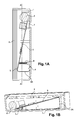
- FIGS. 1A to 1D are views in longitudinal section of a first embodiment of a splitter according to the invention, as well as the corresponding electronic card.
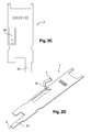
- FIGS. 2A to 2D are views in longitudinal section of a second embodiment of a splitter according to the invention, and the corresponding electronic card.
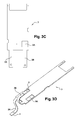
- FIGS. 3A to 3D are views in longitudinal section of a third embodiment of a splitter according to the invention, and the corresponding electronic card.
- a heating cost splitter for attachment to a heating element comprises a housing 1 disposed on a rear adapter 2 for attachment to the heating element, for example a heater.
- This housing 1 contains an electronic card 3 connected to a battery 6 and connected to a screen 7, to a first temperature sensor 4 for measuring the external temperature of the workpiece and disposed near or against the housing 1 and at a second temperature sensor 5 for measuring the temperature of the heating element and disposed near or against the adapter 2.
- the electronic card 3 comprises at least one flexible arm 3A made in one piece with this card and carrying the first temperature sensor 4 for the measurement of the external temperature.
- This first temperature sensor 4 intended for measuring the external temperature is preferably arranged at the end of the flexible arm 3A.
- the electronic card 3 is arranged inclined with respect to the longitudinal plane AA of the distributor and the second temperature sensor 5 for measuring the temperature of the heating element is carried by one end of the electronic card 3 to come against the adapter 2 or near the adapter 2, this electronic card being pushed by a spring element 8 towards the this adapter 2.
- the flexible arm 3A is shaped near the same end of the electronic card 3 and is bent over the width of the distributor to come place the first temperature sensor 4 against the housing 1 or near the housing 1.
- the electronic card 3 is then shaped as illustrated on the Figures 1C and 1D .
- the flexible arm 3A has at its lower end the flexible arm 3A and advantageously another non-flexible arm 3D.
- the end of the flexible arm 3A is equipped with the first temperature sensor 4 intended for measuring the external temperature and the end of the non-flexible arm 3D is equipped with the second temperature sensor 5 intended for measuring the temperature of the heating element.
- the flexible arm 3A is then bent as illustrated on the figure 1D for arranging the electronic card 3 and the sensors in the housing 1 as illustrated on the Figures 1A and 1B .
- the flexible arm 3A is shaped on the surface of the electronic card 3 at a distance from the end of the electronic card 3 carrying the second sensor 5 for measuring the temperature of the heating element and is bent over a lower width to place the first temperature sensor 4 against the housing 1 or near the housing 1.
- the electronic card 3 is then shaped as illustrated on the Figures 2C and 2D .
- the flexible arm 3A is formed by a cut made in the card 3.
- the end of the flexible arm 3A is equipped with the first sensor of temperature 4 for measuring the external temperature and the end of the non-flexible arm 3D is equipped with the second temperature sensor 5 for measuring the temperature of the heating element.
- the flexible arm 3A is then bent as illustrated on the 2D figure for arranging the electronic card 3 and the sensors in the housing 1 as illustrated on the Figures 2A and 2B .
- the electronic card 3 comprises a second flexible arm 3B made in one piece with this card and carrying the second temperature sensor 5 for measuring the temperature of the heating element.
- This second temperature sensor 5 for measuring the temperature of the heating element is preferably disposed at the end of the second flexible arm 3B.
- the electronic card 3 is arranged in a plane parallel to the longitudinal plane AA of the distributor and the two flexible arms 3A and 3B are shaped close to one end of the electronic card 3 and are curved on both sides. other of the card 3 to place the temperature sensors 4 and 5 against the housing 1 and the adapter 2 or near the housing 1 and the adapter 2.
- a piston-type arrangement 9 biased by a spring element and of fixed axis formed in the housing 1 passes through the electronic card 3 and ensures the pressure of the second sensor 5 against the adapter 2.
- the electronic card 3 is then shaped as illustrated on the Figures 3C and 3D .
- the flexible arm 3A has at its lower end the flexible arm 3A and the other flexible arm 3B.
- the end of the flexible arm 3A is equipped with the first temperature sensor 4 for measuring the external temperature and the end of the other flexible arm 3B is equipped with the second temperature sensor 5 for measuring the temperature of the heating element.
- the card 3 also has an orifice 9A in order to allow the passage of the piston-type arrangement 9.
- the flexible arms 3A, 3B are then bent as shown in FIG. 3D figure for arranging the electronic card 3 and the sensors in the housing 1 as illustrated on the Figures 3A and 3B .
Landscapes
- Engineering & Computer Science (AREA)
- Physics & Mathematics (AREA)
- General Physics & Mathematics (AREA)
- Business, Economics & Management (AREA)
- Chemical & Material Sciences (AREA)
- Combustion & Propulsion (AREA)
- Economics (AREA)
- Health & Medical Sciences (AREA)
- Water Supply & Treatment (AREA)
- Marketing (AREA)
- Mechanical Engineering (AREA)
- Public Health (AREA)
- Thermal Sciences (AREA)
- General Health & Medical Sciences (AREA)
- Human Resources & Organizations (AREA)
- General Engineering & Computer Science (AREA)
- Primary Health Care (AREA)
- Strategic Management (AREA)
- Tourism & Hospitality (AREA)
- General Business, Economics & Management (AREA)
- Theoretical Computer Science (AREA)
- Measuring Temperature Or Quantity Of Heat (AREA)
- Testing Or Calibration Of Command Recording Devices (AREA)
- Distribution Board (AREA)
Abstract
Description
- L'invention concerne un répartiteur de coût de chauffage.
- Elle concerne plus précisément un répartiteur de coût de chauffage destiné à être fixé sur un élément chauffant, par exemple un radiateur, et comportant dans un boîtier une carte électronique connectée à un premier capteur de température destiné à la mesure de la température externe de la pièce et à un second capteur de température destiné à la mesure de la température de l'élément chauffant.
- Le document de brevet
DE 10 2009 005 490 décrit un tel répartiteur de coût de chauffage. - Selon ce document, le second capteur de température destiné à la mesure de la température de l'élément chauffant est fixé à l'extrémité d'un bras flexible réalisé d'une pièce avec la carte électronique.
- Ce document ne précise aucune constitution de disposition du premier capteur de température destiné à la mesure de la température externe de la pièce et la carte électronique, selon ce document, est disposée parallèlement à la partie arrière du boîtier destiné à être appliqué à l'élément chauffant. Cette disposition de la carte électronique est dépendante des agencements de disposition des deux capteurs.
- Le but de l'invention est de réaliser le couplage du premier capteur de température destiné à la mesure de la température externe de la pièce, de façon simple techniquement et de façon économique et de façon à permettre une très grande liberté de positionnement de la carte électronique au sein du boîtier qui peut être parallèle à la partie arrière du boîtier destiné à être appliqué à l'élément chauffant ou non, tout en permettant de positionner ce premier capteur et de réaliser les couplages thermiques de façon optimale.
- Pour ce faire, l'invention propose un répartiteur de coût de chauffage destiné à être fixé sur un élément chauffant et comportant dans un boîtier une carte électronique connectée à un premier capteur de température destiné à la mesure de la température externe et à un second capteur de température destiné à la mesure de la température dudit élément chauffant, caractérisé en ce que ladite carte électronique comporte au moins un bras flexible réalisé d'une seule pièce avec cette carte et portant ledit premier capteur.
- Selon un mode de réalisation préféré de l'invention, ledit premier capteur de température destiné à la mesure de la température externe est disposé à l'extrémité dudit bras flexible.
- Ladite carte électronique peut être disposée de façon inclinée par rapport à un plan perpendiculaire à un axe longitudinal du répartiteur et ledit second capteur destiné à la mesure de la température dudit élément chauffant être porté par une extrémité de cette carte électronique pour venir à proximité dudit élément chauffant.
- Ladite carte électronique peut comporter un second bras flexible réalisé d'une seule pièce avec cette carte et portant ledit second capteur de température destiné à la mesure de la température dudit élément chauffant.
- Dans ce cas, de préférence, ledit second capteur de température destiné à la mesure de la température dudit élément chauffant est disposé à l'extrémité dudit second bras flexible.
- Le répartiteur peut comporter un agencement de type piston traversant ladite carte électronique et poussant ledit second capteur contre ledit adaptateur.
- L'invention est décrite ci-après plus en détail à l'aide de figures représentant des modes de réalisation préférés de l'invention.
- Les
figures 1A à 1D sont des vues en coupe longitudinale d'un premier mode de réalisation d'un répartiteur conforme à l'invention, ainsi que de la carte électronique correspondante. - Les
figures 2A à 2D sont des vues en coupe longitudinale d'un deuxième mode de réalisation d'un répartiteur conforme à l'invention, ainsi que de la carte électronique correspondante. - Les
figures 3A à 3D sont des vues en coupe longitudinale d'un troisième mode de réalisation d'un répartiteur conforme à l'invention, ainsi que de la carte électronique correspondante. - Comme représenté sur les figures, un répartiteur de coût de chauffage destiné à être fixé sur un élément chauffant comporte un boîtier 1 disposé sur un adaptateur arrière 2 destiné à être fixé sur l'élément chauffant, par exemple un radiateur.
- Ce boîtier 1 contient une carte électronique 3 reliée une batterie 6 et connectée à un écran 7, à un premier capteur de température 4 destiné à la mesure de la température externe de la pièce et disposé à proximité du ou contre le boîtier 1 et à un second capteur de température 5 destiné à la mesure de la température de l'élément chauffant et disposé à proximité de ou contre l'adaptateur 2.
- Selon l'invention, la carte électronique 3 comporte au moins un bras flexible 3A réalisé d'une seule pièce avec cette carte et portant le premier capteur de température 4 destiné à la mesure de la température externe. Ce premier capteur de température 4 destiné à la mesure de la température externe est de préférence disposé à l'extrémité du bras flexible 3A.
- Selon un premier mode de réalisation représenté sur les
figures 1A, 1B ,2A et 2B , la carte électronique 3 est disposée de façon inclinée par rapport au plan longitudinal A-A du répartiteur et le second capteur de température 5 destiné à la mesure de la température de l'élément chauffant est porté par une extrémité de cette carte électronique 3 pour venir contre l'adaptateur 2 ou à proximité de l'adaptateur 2, cette carte électronique étant poussé par un élément de ressort 8 en direction de cet adaptateur 2. - Selon une première variante représentée sur la
figure 1A et 1B , le bras flexible 3A est conformé à proximité de cette même extrémité de la carte électronique 3 et est recourbé sur la largeur du répartiteur pour venir placer le premier capteur de température 4 contre le boîtier 1 ou à proximité du boîtier 1. - La carte électronique 3 est alors conformée comme illustrée sur les
figures 1C et 1D . - Vue selon les figures, elle comporte à son extrémité inférieure le bras flexible 3A et avantageusement un autre bras non flexible 3D. L'extrémité du bras flexible 3A est équipée du premier capteur de température 4 destiné à la mesure de la température externe et l'extrémité du bras non flexible 3D est équipée du second capteur de température 5 destiné à la mesure de la température de l'élément chauffant. Le bras flexible 3A est ensuite recourbé comme illustré sur la
figure 1D pour disposer la carte électronique 3 et les capteurs dans le boîtier 1 comme illustré sur lesfigures 1A et 1B . - Selon une seconde variante représentée sur la
figure 2A et 2B , le bras flexible 3A est conformé sur la surface de la carte électronique 3 à une distance de l'extrémité de la carte électronique 3 portant le second capteur 5 destiné à la mesure de la température de l'élément chauffant et il est recourbé sur une largeur inférieure pour venir placer le premier capteur de température 4 contre le boîtier 1 ou à proximité du boîtier 1. - La carte électronique 3 est alors conformée comme illustrée sur les
figures 2C et 2D . - Vue selon les figures, elle comporte à son extrémité inférieure un bras non flexible 3D, comme selon la première variante. Le bras flexible 3A est quant à lui formé par une découpe réalisé dans la carte 3. L'extrémité du bras flexible 3A est équipée du premier capteur de température 4 destiné à la mesure de la température externe et l'extrémité du bras non flexible 3D est équipée du second capteur de température 5 destiné à la mesure de la température de l'élément chauffant. Le bras flexible 3A est ensuite recourbé comme illustré sur la
figure 2D pour disposer la carte électronique 3 et les capteurs dans le boîtier 1 comme illustré sur lesfigures 2A et 2B . - Selon un second mode de réalisation représenté sur la
figure 3A et 3B , la carte électronique 3 comporte un second bras flexible 3B réalisé d'une seule pièce avec cette carte et portant le second capteur de température 5 destiné à la mesure de la température de l'élément chauffant. Ce second capteur de température 5 destiné à la mesure de la température de l'élément chauffant est de préférence disposé à l'extrémité de ce second bras flexible 3B. - Dans ce cas, avantageusement, la carte électronique 3 est disposé dans un plan parallèle au plan longitudinal A-A du répartiteur et les deux bras flexibles 3A et 3B sont conformés à proximité d'une extrémité de la carte électronique 3 et sont recourbés de part et d'autre de la carte 3 pour venir placer les capteurs de température 4 et 5 contre le boîtier 1 et l'adaptateur 2 ou à proximité du boîtier 1 et de l'adaptateur 2.
- Avantageusement, un agencement de type piston 9 sollicité par un élément de ressort et d'axe fixe conformé dans le boîtier 1 traverse la carte électronique 3 et assure la pression du second capteur 5 contre l'adaptateur 2.
- La carte électronique 3 est alors conformée comme illustrée sur les
figures 3C et 3D . - Vue selon les figures, elle comporte à son extrémité inférieure le bras flexible 3A et l'autre bras flexible 3B. L'extrémité du bras flexible 3A est équipée du premier capteur de température 4 destiné à la mesure de la température externe et l'extrémité de l'autre bras flexible 3B est équipée du second capteur de température 5 destiné à la mesure de la température de l'élément chauffant.
- La carte 3 présente également un orifice 9A afin de permettre le passage de l'agencement de type piston 9.
- Les bras flexibles 3A, 3B sont ensuite recourbés comme illustré sur la
figure 3D pour disposer la carte électronique 3 et les capteurs dans le boîtier 1 comme illustré sur lesfigures 3A et 3B .
Claims (6)
- Répartiteur de coût de chauffage destiné à être fixé sur un élément chauffant et comportant dans un boîtier (1) une carte électronique (3) connectée à un premier capteur de température (4) destiné à la mesure de la température externe et disposé à proximité dudit boîtier et à un second capteur de température (5) destiné à la mesure de la température dudit élément chauffant et disposé à proximité dudit élément chauffant, caractérisé en ce que ladite carte électronique (3) comporte au moins un bras flexible (3A) réalisé d'une seule pièce avec cette carte et portant ledit premier capteur de température (4) destiné à la mesure de la température externe.
- Répartiteur selon la revendication précédente, caractérisé en ce que ledit premier capteur de température (4) destiné à la mesure de la température externe est disposé à l'extrémité dudit bras flexible (3A).
- Répartiteur selon l'une des revendications précédentes, caractérisé en ce que ladite carte électronique (3) est disposée de façon inclinée par rapport à un plan longitudinal (A-A) du répartiteur et en ce que ledit second capteur (5) destiné à la mesure de la température dudit élément chauffant est porté par une extrémité de cette carte électronique (3) pour venir à proximité dudit élément chauffant.
- Répartiteur selon la revendication 1 ou 2, caractérisé en ce que ladite carte électronique (3) comporte un second bras flexible (3B) réalisé d'une seule pièce avec cette carte et portant ledit second capteur de température (5) destiné à la mesure de la température dudit élément chauffant.
- Répartiteur selon la revendication précédente, caractérisé en ce que ledit second capteur de température (5) destiné à la mesure de la température dudit élément chauffant est disposé à l'extrémité dudit second bras flexible (3B).
- Répartiteur selon la revendication 4 ou 5, caractérisé en ce qu'il comporte un agencement de type piston (9) traversant ladite carte électronique (3) et poussant ledit second capteur (5) contre ledit adaptateur (2).
Priority Applications (5)
| Application Number | Priority Date | Filing Date | Title |
|---|---|---|---|
| DK11305446.4T DK2511616T3 (en) | 2011-04-14 | 2011-04-14 | Heating cost distributor. |
| EP11305446.4A EP2511616B1 (fr) | 2011-04-14 | 2011-04-14 | Repartiteur de cout de chauffage |
| RU2012101987/12A RU2012101987A (ru) | 2011-04-14 | 2012-01-20 | Устройство распределения стоимости отопления |
| CN2012100345313A CN102734861A (zh) | 2011-04-14 | 2012-02-16 | 用于分配加热成本的分配器 |
| KR1020120016594A KR101891100B1 (ko) | 2011-04-14 | 2012-02-17 | 난방 비용을 분배하기 위한 분배기 |
Applications Claiming Priority (1)
| Application Number | Priority Date | Filing Date | Title |
|---|---|---|---|
| EP11305446.4A EP2511616B1 (fr) | 2011-04-14 | 2011-04-14 | Repartiteur de cout de chauffage |
Publications (2)
| Publication Number | Publication Date |
|---|---|
| EP2511616A1 true EP2511616A1 (fr) | 2012-10-17 |
| EP2511616B1 EP2511616B1 (fr) | 2016-07-06 |
Family
ID=44544077
Family Applications (1)
| Application Number | Title | Priority Date | Filing Date |
|---|---|---|---|
| EP11305446.4A Not-in-force EP2511616B1 (fr) | 2011-04-14 | 2011-04-14 | Repartiteur de cout de chauffage |
Country Status (5)
| Country | Link |
|---|---|
| EP (1) | EP2511616B1 (fr) |
| KR (1) | KR101891100B1 (fr) |
| CN (1) | CN102734861A (fr) |
| DK (1) | DK2511616T3 (fr) |
| RU (1) | RU2012101987A (fr) |
Cited By (2)
| Publication number | Priority date | Publication date | Assignee | Title |
|---|---|---|---|---|
| DE102020122803A1 (de) | 2020-09-01 | 2022-03-03 | Endress+Hauser Flowtec Ag | Messgerät |
| DE102021120159A1 (de) | 2021-08-03 | 2023-02-09 | HELLA GmbH & Co. KGaA | Sensorvorrichtung zur Erfassung der Temperatur an einem flächigen Bauteil, insbesondere an einer Scheibe eines Fahrzeuges |
Families Citing this family (1)
| Publication number | Priority date | Publication date | Assignee | Title |
|---|---|---|---|---|
| FR3108719B1 (fr) * | 2020-03-24 | 2022-04-08 | A Raymond Et Cie | Procédé de fabrication d’un dispositif de mesure de température destiné à être connecté à un raccord de connexion fluidique, et ensemble intermédiaire associé |
Citations (7)
| Publication number | Priority date | Publication date | Assignee | Title |
|---|---|---|---|---|
| EP1077366A2 (fr) * | 1999-08-19 | 2001-02-21 | Diehl Controls Nürnberg GmbH & Co. KG | Distributeur électronique de frais de chauffage |
| DE202004007802U1 (de) * | 2004-05-14 | 2005-09-22 | Diehl Ako Stiftung & Co. Kg | Elektronischer Heizkostenverteiler |
| EP1605238A1 (fr) * | 2004-05-14 | 2005-12-14 | Diehl AKO Stiftung & Co. KG | Distributeur électronique de frais de chauffage |
| EP1925924A1 (fr) * | 2006-11-21 | 2008-05-28 | Siemens Building Technologies electronic GmbH | Répartiteur de frais de chauffage à bas coût |
| DE202008009279U1 (de) * | 2008-07-10 | 2009-11-12 | Meßtechnik Gesellschaft m.b.H. & Co. KG Energieverrechnung-Contracting-Facility Management | Vorrichtung zum Erfassen der Wärmeabgabe eines Heizkörpers |
| DE102009005490B3 (de) | 2009-01-21 | 2010-07-08 | Qundis Gmbh | Elektronischer Heizkostenverteiler |
| DE102010003967B3 (de) * | 2010-01-02 | 2011-02-10 | Qundis Gmbh | Heizkostenverteiler |
Family Cites Families (1)
| Publication number | Priority date | Publication date | Assignee | Title |
|---|---|---|---|---|
| CN101122530A (zh) * | 2006-08-09 | 2008-02-13 | 天津市津南区凯达电子有限公司 | 可帖附安装在暖气片上的新型热量表 |
-
2011
- 2011-04-14 DK DK11305446.4T patent/DK2511616T3/en active
- 2011-04-14 EP EP11305446.4A patent/EP2511616B1/fr not_active Not-in-force
-
2012
- 2012-01-20 RU RU2012101987/12A patent/RU2012101987A/ru not_active Application Discontinuation
- 2012-02-16 CN CN2012100345313A patent/CN102734861A/zh active Pending
- 2012-02-17 KR KR1020120016594A patent/KR101891100B1/ko not_active Expired - Fee Related
Patent Citations (7)
| Publication number | Priority date | Publication date | Assignee | Title |
|---|---|---|---|---|
| EP1077366A2 (fr) * | 1999-08-19 | 2001-02-21 | Diehl Controls Nürnberg GmbH & Co. KG | Distributeur électronique de frais de chauffage |
| DE202004007802U1 (de) * | 2004-05-14 | 2005-09-22 | Diehl Ako Stiftung & Co. Kg | Elektronischer Heizkostenverteiler |
| EP1605238A1 (fr) * | 2004-05-14 | 2005-12-14 | Diehl AKO Stiftung & Co. KG | Distributeur électronique de frais de chauffage |
| EP1925924A1 (fr) * | 2006-11-21 | 2008-05-28 | Siemens Building Technologies electronic GmbH | Répartiteur de frais de chauffage à bas coût |
| DE202008009279U1 (de) * | 2008-07-10 | 2009-11-12 | Meßtechnik Gesellschaft m.b.H. & Co. KG Energieverrechnung-Contracting-Facility Management | Vorrichtung zum Erfassen der Wärmeabgabe eines Heizkörpers |
| DE102009005490B3 (de) | 2009-01-21 | 2010-07-08 | Qundis Gmbh | Elektronischer Heizkostenverteiler |
| DE102010003967B3 (de) * | 2010-01-02 | 2011-02-10 | Qundis Gmbh | Heizkostenverteiler |
Cited By (3)
| Publication number | Priority date | Publication date | Assignee | Title |
|---|---|---|---|---|
| DE102020122803A1 (de) | 2020-09-01 | 2022-03-03 | Endress+Hauser Flowtec Ag | Messgerät |
| US12578234B2 (en) | 2020-09-01 | 2026-03-17 | Endress+Hauser Flowtec Ag | Measuring device |
| DE102021120159A1 (de) | 2021-08-03 | 2023-02-09 | HELLA GmbH & Co. KGaA | Sensorvorrichtung zur Erfassung der Temperatur an einem flächigen Bauteil, insbesondere an einer Scheibe eines Fahrzeuges |
Also Published As
| Publication number | Publication date |
|---|---|
| KR20120117631A (ko) | 2012-10-24 |
| CN102734861A (zh) | 2012-10-17 |
| EP2511616B1 (fr) | 2016-07-06 |
| RU2012101987A (ru) | 2013-07-27 |
| DK2511616T3 (en) | 2016-10-03 |
| KR101891100B1 (ko) | 2018-08-23 |
Similar Documents
| Publication | Publication Date | Title |
|---|---|---|
| BE1004553A5 (fr) | Procede d'assemblage d'un dispositif palpeur de temperature et dispositif palpeur ainsi obtenu. | |
| EP2511616B1 (fr) | Repartiteur de cout de chauffage | |
| MX2009013051A (es) | Base de conexion que interactua con un adaptador para formar con el mismo un conector mecanico para la hoja del limpiaparabrisas para un automovil. | |
| EP2861472B1 (fr) | Balai d'essuyage a connecteur hydraulique | |
| EP2112713B1 (fr) | Borne de raccordement et appareil électrique basse tension | |
| WO2005050078A3 (fr) | Dispositif d'actionnement pour couplage a raccordement rapide | |
| EP2812214B1 (fr) | Element de fixation d'un organe fonctionnel pour vehicule automobile | |
| EP2191752B1 (fr) | Fontaine à eau chaude | |
| EP1600653B1 (fr) | Ressort de maintien et de guidage d'un moyen de friction et frein à disque muni d'au moins un tel ressort | |
| EP1936255A1 (fr) | Robinet pour réservoir de gaz sous pression et réservoir comportant un tel robinet | |
| EP2388042A3 (fr) | Connecteur pour un circuit de liquide | |
| FR3032561B1 (fr) | Dispositif de connexion d’une source lumineuse a un dispositif d’alimentation electrique | |
| FR2984262A1 (fr) | Interface hydraulique d'un dispositif d'essuyage d'une vitre d'un vehicule automobile | |
| EP2228879B1 (fr) | Compteur équipé d'un agencement de fixation d'un câble électrique | |
| FR2979602B1 (fr) | Dispositif d'emballage et emballage pour balai d'essuie-glace a lame courbe et structure flexible integree | |
| FR2947620A1 (fr) | Pied pour sonde de geothermie | |
| FR3056675A1 (fr) | Robinet pour fluide sous pression | |
| EP2696122B1 (fr) | Dispositif de détection de position de tiroir de distributeur pneumatique | |
| EP1987335B1 (fr) | Compteur d'energie thermique | |
| FR3044761A1 (fr) | Capteur de pression et appareil de fluide sous pression comprenant un tel capteur. | |
| EP2851917B1 (fr) | Interrupteur de position | |
| EP2618121B1 (fr) | Répartiteur de coût de chauffage et câble de liaison pour montage déporté | |
| EP2549251A1 (fr) | Repartiteur de cout de chauffage | |
| FR2978523A3 (fr) | Dispositif de fixation d'un element sensible a la chaleur sur une piece chaude d'un vehicule. | |
| FR3003031A1 (fr) | Dispositif de controle de surpression pour un transmetteur de pression |
Legal Events
| Date | Code | Title | Description |
|---|---|---|---|
| PUAI | Public reference made under article 153(3) epc to a published international application that has entered the european phase |
Free format text: ORIGINAL CODE: 0009012 |
|
| 17P | Request for examination filed |
Effective date: 20120118 |
|
| AK | Designated contracting states |
Kind code of ref document: A1 Designated state(s): AL AT BE BG CH CY CZ DE DK EE ES FI FR GB GR HR HU IE IS IT LI LT LU LV MC MK MT NL NO PL PT RO RS SE SI SK SM TR |
|
| AX | Request for extension of the european patent |
Extension state: BA ME |
|
| 17Q | First examination report despatched |
Effective date: 20130703 |
|
| GRAP | Despatch of communication of intention to grant a patent |
Free format text: ORIGINAL CODE: EPIDOSNIGR1 |
|
| INTG | Intention to grant announced |
Effective date: 20160127 |
|
| RIN1 | Information on inventor provided before grant (corrected) |
Inventor name: ARNAUD-GODET, BRICE Inventor name: ABELARD, TRISTAN Inventor name: GUILLOT-JEROME, DENIS Inventor name: GIRAUD, OLIVIER |
|
| GRAS | Grant fee paid |
Free format text: ORIGINAL CODE: EPIDOSNIGR3 |
|
| GRAA | (expected) grant |
Free format text: ORIGINAL CODE: 0009210 |
|
| AK | Designated contracting states |
Kind code of ref document: B1 Designated state(s): AL AT BE BG CH CY CZ DE DK EE ES FI FR GB GR HR HU IE IS IT LI LT LU LV MC MK MT NL NO PL PT RO RS SE SI SK SM TR |
|
| REG | Reference to a national code |
Ref country code: GB Ref legal event code: FG4D Free format text: NOT ENGLISH |
|
| REG | Reference to a national code |
Ref country code: AT Ref legal event code: REF Ref document number: 811002 Country of ref document: AT Kind code of ref document: T Effective date: 20160715 Ref country code: CH Ref legal event code: EP |
|
| REG | Reference to a national code |
Ref country code: IE Ref legal event code: FG4D Free format text: LANGUAGE OF EP DOCUMENT: FRENCH |
|
| REG | Reference to a national code |
Ref country code: DE Ref legal event code: R096 Ref document number: 602011027907 Country of ref document: DE |
|
| REG | Reference to a national code |
Ref country code: DK Ref legal event code: T3 Effective date: 20160929 |
|
| REG | Reference to a national code |
Ref country code: NL Ref legal event code: MP Effective date: 20160706 |
|
| REG | Reference to a national code |
Ref country code: LT Ref legal event code: MG4D |
|
| REG | Reference to a national code |
Ref country code: AT Ref legal event code: MK05 Ref document number: 811002 Country of ref document: AT Kind code of ref document: T Effective date: 20160706 |
|
| REG | Reference to a national code |
Ref country code: DE Ref legal event code: R081 Ref document number: 602011027907 Country of ref document: DE Owner name: ITRON GLOBAL SARL, LIBERTY LAKE, US Free format text: FORMER OWNER: ITRON FRANCE, BOULOGNE-BILLANCOURT, FR Ref country code: DE Ref legal event code: R082 Ref document number: 602011027907 Country of ref document: DE Representative=s name: KILBURN & STRODE LLP, GB |
|
| PG25 | Lapsed in a contracting state [announced via postgrant information from national office to epo] |
Ref country code: IS Free format text: LAPSE BECAUSE OF FAILURE TO SUBMIT A TRANSLATION OF THE DESCRIPTION OR TO PAY THE FEE WITHIN THE PRESCRIBED TIME-LIMIT Effective date: 20161106 Ref country code: NL Free format text: LAPSE BECAUSE OF FAILURE TO SUBMIT A TRANSLATION OF THE DESCRIPTION OR TO PAY THE FEE WITHIN THE PRESCRIBED TIME-LIMIT Effective date: 20160706 Ref country code: LT Free format text: LAPSE BECAUSE OF FAILURE TO SUBMIT A TRANSLATION OF THE DESCRIPTION OR TO PAY THE FEE WITHIN THE PRESCRIBED TIME-LIMIT Effective date: 20160706 Ref country code: NO Free format text: LAPSE BECAUSE OF FAILURE TO SUBMIT A TRANSLATION OF THE DESCRIPTION OR TO PAY THE FEE WITHIN THE PRESCRIBED TIME-LIMIT Effective date: 20161006 Ref country code: HR Free format text: LAPSE BECAUSE OF FAILURE TO SUBMIT A TRANSLATION OF THE DESCRIPTION OR TO PAY THE FEE WITHIN THE PRESCRIBED TIME-LIMIT Effective date: 20160706 Ref country code: FI Free format text: LAPSE BECAUSE OF FAILURE TO SUBMIT A TRANSLATION OF THE DESCRIPTION OR TO PAY THE FEE WITHIN THE PRESCRIBED TIME-LIMIT Effective date: 20160706 Ref country code: RS Free format text: LAPSE BECAUSE OF FAILURE TO SUBMIT A TRANSLATION OF THE DESCRIPTION OR TO PAY THE FEE WITHIN THE PRESCRIBED TIME-LIMIT Effective date: 20160706 |
|
| PG25 | Lapsed in a contracting state [announced via postgrant information from national office to epo] |
Ref country code: ES Free format text: LAPSE BECAUSE OF FAILURE TO SUBMIT A TRANSLATION OF THE DESCRIPTION OR TO PAY THE FEE WITHIN THE PRESCRIBED TIME-LIMIT Effective date: 20160706 Ref country code: PT Free format text: LAPSE BECAUSE OF FAILURE TO SUBMIT A TRANSLATION OF THE DESCRIPTION OR TO PAY THE FEE WITHIN THE PRESCRIBED TIME-LIMIT Effective date: 20161107 Ref country code: PL Free format text: LAPSE BECAUSE OF FAILURE TO SUBMIT A TRANSLATION OF THE DESCRIPTION OR TO PAY THE FEE WITHIN THE PRESCRIBED TIME-LIMIT Effective date: 20160706 Ref country code: AT Free format text: LAPSE BECAUSE OF FAILURE TO SUBMIT A TRANSLATION OF THE DESCRIPTION OR TO PAY THE FEE WITHIN THE PRESCRIBED TIME-LIMIT Effective date: 20160706 Ref country code: LV Free format text: LAPSE BECAUSE OF FAILURE TO SUBMIT A TRANSLATION OF THE DESCRIPTION OR TO PAY THE FEE WITHIN THE PRESCRIBED TIME-LIMIT Effective date: 20160706 Ref country code: GR Free format text: LAPSE BECAUSE OF FAILURE TO SUBMIT A TRANSLATION OF THE DESCRIPTION OR TO PAY THE FEE WITHIN THE PRESCRIBED TIME-LIMIT Effective date: 20161007 Ref country code: SE Free format text: LAPSE BECAUSE OF FAILURE TO SUBMIT A TRANSLATION OF THE DESCRIPTION OR TO PAY THE FEE WITHIN THE PRESCRIBED TIME-LIMIT Effective date: 20160706 |
|
| REG | Reference to a national code |
Ref country code: FR Ref legal event code: PLFP Year of fee payment: 7 |
|
| REG | Reference to a national code |
Ref country code: DE Ref legal event code: R097 Ref document number: 602011027907 Country of ref document: DE |
|
| PG25 | Lapsed in a contracting state [announced via postgrant information from national office to epo] |
Ref country code: EE Free format text: LAPSE BECAUSE OF FAILURE TO SUBMIT A TRANSLATION OF THE DESCRIPTION OR TO PAY THE FEE WITHIN THE PRESCRIBED TIME-LIMIT Effective date: 20160706 Ref country code: RO Free format text: LAPSE BECAUSE OF FAILURE TO SUBMIT A TRANSLATION OF THE DESCRIPTION OR TO PAY THE FEE WITHIN THE PRESCRIBED TIME-LIMIT Effective date: 20160706 |
|
| PLBE | No opposition filed within time limit |
Free format text: ORIGINAL CODE: 0009261 |
|
| STAA | Information on the status of an ep patent application or granted ep patent |
Free format text: STATUS: NO OPPOSITION FILED WITHIN TIME LIMIT |
|
| PG25 | Lapsed in a contracting state [announced via postgrant information from national office to epo] |
Ref country code: CZ Free format text: LAPSE BECAUSE OF FAILURE TO SUBMIT A TRANSLATION OF THE DESCRIPTION OR TO PAY THE FEE WITHIN THE PRESCRIBED TIME-LIMIT Effective date: 20160706 Ref country code: BG Free format text: LAPSE BECAUSE OF FAILURE TO SUBMIT A TRANSLATION OF THE DESCRIPTION OR TO PAY THE FEE WITHIN THE PRESCRIBED TIME-LIMIT Effective date: 20161006 Ref country code: SK Free format text: LAPSE BECAUSE OF FAILURE TO SUBMIT A TRANSLATION OF THE DESCRIPTION OR TO PAY THE FEE WITHIN THE PRESCRIBED TIME-LIMIT Effective date: 20160706 Ref country code: SM Free format text: LAPSE BECAUSE OF FAILURE TO SUBMIT A TRANSLATION OF THE DESCRIPTION OR TO PAY THE FEE WITHIN THE PRESCRIBED TIME-LIMIT Effective date: 20160706 |
|
| 26N | No opposition filed |
Effective date: 20170407 |
|
| REG | Reference to a national code |
Ref country code: FR Ref legal event code: CA Effective date: 20170601 Ref country code: FR Ref legal event code: TP Owner name: ITRON GLOBAL SARL, US Effective date: 20170601 |
|
| PG25 | Lapsed in a contracting state [announced via postgrant information from national office to epo] |
Ref country code: SI Free format text: LAPSE BECAUSE OF FAILURE TO SUBMIT A TRANSLATION OF THE DESCRIPTION OR TO PAY THE FEE WITHIN THE PRESCRIBED TIME-LIMIT Effective date: 20160706 |
|
| REG | Reference to a national code |
Ref country code: CH Ref legal event code: PL |
|
| REG | Reference to a national code |
Ref country code: GB Ref legal event code: 732E Free format text: REGISTERED BETWEEN 20171116 AND 20171122 |
|
| REG | Reference to a national code |
Ref country code: IE Ref legal event code: MM4A |
|
| PG25 | Lapsed in a contracting state [announced via postgrant information from national office to epo] |
Ref country code: MC Free format text: LAPSE BECAUSE OF FAILURE TO SUBMIT A TRANSLATION OF THE DESCRIPTION OR TO PAY THE FEE WITHIN THE PRESCRIBED TIME-LIMIT Effective date: 20160706 |
|
| PG25 | Lapsed in a contracting state [announced via postgrant information from national office to epo] |
Ref country code: LI Free format text: LAPSE BECAUSE OF NON-PAYMENT OF DUE FEES Effective date: 20170430 Ref country code: CH Free format text: LAPSE BECAUSE OF NON-PAYMENT OF DUE FEES Effective date: 20170430 Ref country code: LU Free format text: LAPSE BECAUSE OF NON-PAYMENT OF DUE FEES Effective date: 20170414 |
|
| REG | Reference to a national code |
Ref country code: FR Ref legal event code: PLFP Year of fee payment: 8 |
|
| REG | Reference to a national code |
Ref country code: BE Ref legal event code: MM Effective date: 20170430 |
|
| PG25 | Lapsed in a contracting state [announced via postgrant information from national office to epo] |
Ref country code: IE Free format text: LAPSE BECAUSE OF NON-PAYMENT OF DUE FEES Effective date: 20170414 |
|
| PGFP | Annual fee paid to national office [announced via postgrant information from national office to epo] |
Ref country code: GB Payment date: 20180329 Year of fee payment: 8 |
|
| PG25 | Lapsed in a contracting state [announced via postgrant information from national office to epo] |
Ref country code: BE Free format text: LAPSE BECAUSE OF NON-PAYMENT OF DUE FEES Effective date: 20170430 |
|
| PGFP | Annual fee paid to national office [announced via postgrant information from national office to epo] |
Ref country code: FR Payment date: 20180315 Year of fee payment: 8 |
|
| PGFP | Annual fee paid to national office [announced via postgrant information from national office to epo] |
Ref country code: DE Payment date: 20180404 Year of fee payment: 8 Ref country code: DK Payment date: 20180410 Year of fee payment: 8 |
|
| PGFP | Annual fee paid to national office [announced via postgrant information from national office to epo] |
Ref country code: IT Payment date: 20180420 Year of fee payment: 8 |
|
| PG25 | Lapsed in a contracting state [announced via postgrant information from national office to epo] |
Ref country code: MT Free format text: LAPSE BECAUSE OF FAILURE TO SUBMIT A TRANSLATION OF THE DESCRIPTION OR TO PAY THE FEE WITHIN THE PRESCRIBED TIME-LIMIT Effective date: 20160706 |
|
| PG25 | Lapsed in a contracting state [announced via postgrant information from national office to epo] |
Ref country code: AL Free format text: LAPSE BECAUSE OF FAILURE TO SUBMIT A TRANSLATION OF THE DESCRIPTION OR TO PAY THE FEE WITHIN THE PRESCRIBED TIME-LIMIT Effective date: 20160706 |
|
| PG25 | Lapsed in a contracting state [announced via postgrant information from national office to epo] |
Ref country code: HU Free format text: LAPSE BECAUSE OF FAILURE TO SUBMIT A TRANSLATION OF THE DESCRIPTION OR TO PAY THE FEE WITHIN THE PRESCRIBED TIME-LIMIT; INVALID AB INITIO Effective date: 20110414 |
|
| PG25 | Lapsed in a contracting state [announced via postgrant information from national office to epo] |
Ref country code: CY Free format text: LAPSE BECAUSE OF NON-PAYMENT OF DUE FEES Effective date: 20160706 |
|
| REG | Reference to a national code |
Ref country code: DE Ref legal event code: R119 Ref document number: 602011027907 Country of ref document: DE |
|
| PG25 | Lapsed in a contracting state [announced via postgrant information from national office to epo] |
Ref country code: MK Free format text: LAPSE BECAUSE OF FAILURE TO SUBMIT A TRANSLATION OF THE DESCRIPTION OR TO PAY THE FEE WITHIN THE PRESCRIBED TIME-LIMIT Effective date: 20160706 |
|
| REG | Reference to a national code |
Ref country code: DK Ref legal event code: EBP Effective date: 20190430 |
|
| GBPC | Gb: european patent ceased through non-payment of renewal fee |
Effective date: 20190414 |
|
| PG25 | Lapsed in a contracting state [announced via postgrant information from national office to epo] |
Ref country code: DE Free format text: LAPSE BECAUSE OF NON-PAYMENT OF DUE FEES Effective date: 20191101 Ref country code: GB Free format text: LAPSE BECAUSE OF NON-PAYMENT OF DUE FEES Effective date: 20190414 |
|
| PG25 | Lapsed in a contracting state [announced via postgrant information from national office to epo] |
Ref country code: FR Free format text: LAPSE BECAUSE OF NON-PAYMENT OF DUE FEES Effective date: 20190430 |
|
| PG25 | Lapsed in a contracting state [announced via postgrant information from national office to epo] |
Ref country code: TR Free format text: LAPSE BECAUSE OF FAILURE TO SUBMIT A TRANSLATION OF THE DESCRIPTION OR TO PAY THE FEE WITHIN THE PRESCRIBED TIME-LIMIT Effective date: 20160706 |
|
| PG25 | Lapsed in a contracting state [announced via postgrant information from national office to epo] |
Ref country code: IT Free format text: LAPSE BECAUSE OF NON-PAYMENT OF DUE FEES Effective date: 20190414 Ref country code: DK Free format text: LAPSE BECAUSE OF NON-PAYMENT OF DUE FEES Effective date: 20190430 |