EP2511607A2 - Combustor Nozzle And Method For Supplying Fuel To A Combustor - Google Patents
Combustor Nozzle And Method For Supplying Fuel To A Combustor Download PDFInfo
- Publication number
- EP2511607A2 EP2511607A2 EP12163134A EP12163134A EP2511607A2 EP 2511607 A2 EP2511607 A2 EP 2511607A2 EP 12163134 A EP12163134 A EP 12163134A EP 12163134 A EP12163134 A EP 12163134A EP 2511607 A2 EP2511607 A2 EP 2511607A2
- Authority
- EP
- European Patent Office
- Prior art keywords
- nozzle
- center body
- guide
- combustor
- fuel
- Prior art date
- Legal status (The legal status is an assumption and is not a legal conclusion. Google has not performed a legal analysis and makes no representation as to the accuracy of the status listed.)
- Withdrawn
Links
Images




Classifications
-
- F—MECHANICAL ENGINEERING; LIGHTING; HEATING; WEAPONS; BLASTING
- F23—COMBUSTION APPARATUS; COMBUSTION PROCESSES
- F23C—METHODS OR APPARATUS FOR COMBUSTION USING FLUID FUEL OR SOLID FUEL SUSPENDED IN A CARRIER GAS OR AIR
- F23C7/00—Combustion apparatus characterised by arrangements for air supply
- F23C7/002—Combustion apparatus characterised by arrangements for air supply the air being submitted to a rotary or spinning motion
- F23C7/004—Combustion apparatus characterised by arrangements for air supply the air being submitted to a rotary or spinning motion using vanes
- F23C7/006—Combustion apparatus characterised by arrangements for air supply the air being submitted to a rotary or spinning motion using vanes adjustable
-
- F—MECHANICAL ENGINEERING; LIGHTING; HEATING; WEAPONS; BLASTING
- F23—COMBUSTION APPARATUS; COMBUSTION PROCESSES
- F23D—BURNERS
- F23D14/00—Burners for combustion of a gas, e.g. of a gas stored under pressure as a liquid
- F23D14/46—Details
- F23D14/70—Baffles or like flow-disturbing devices
-
- F—MECHANICAL ENGINEERING; LIGHTING; HEATING; WEAPONS; BLASTING
- F23—COMBUSTION APPARATUS; COMBUSTION PROCESSES
- F23R—GENERATING COMBUSTION PRODUCTS OF HIGH PRESSURE OR HIGH VELOCITY, e.g. GAS-TURBINE COMBUSTION CHAMBERS
- F23R3/00—Continuous combustion chambers using liquid or gaseous fuel
- F23R3/02—Continuous combustion chambers using liquid or gaseous fuel characterised by the air-flow or gas-flow configuration
- F23R3/04—Air inlet arrangements
- F23R3/10—Air inlet arrangements for primary air
- F23R3/12—Air inlet arrangements for primary air inducing a vortex
- F23R3/14—Air inlet arrangements for primary air inducing a vortex by using swirl vanes
-
- F—MECHANICAL ENGINEERING; LIGHTING; HEATING; WEAPONS; BLASTING
- F23—COMBUSTION APPARATUS; COMBUSTION PROCESSES
- F23R—GENERATING COMBUSTION PRODUCTS OF HIGH PRESSURE OR HIGH VELOCITY, e.g. GAS-TURBINE COMBUSTION CHAMBERS
- F23R3/00—Continuous combustion chambers using liquid or gaseous fuel
- F23R3/28—Continuous combustion chambers using liquid or gaseous fuel characterised by the fuel supply
- F23R3/286—Continuous combustion chambers using liquid or gaseous fuel characterised by the fuel supply having fuel-air premixing devices
-
- F—MECHANICAL ENGINEERING; LIGHTING; HEATING; WEAPONS; BLASTING
- F23—COMBUSTION APPARATUS; COMBUSTION PROCESSES
- F23D—BURNERS
- F23D2208/00—Control devices associated with burners
- F23D2208/10—Sensing devices
-
- F—MECHANICAL ENGINEERING; LIGHTING; HEATING; WEAPONS; BLASTING
- F23—COMBUSTION APPARATUS; COMBUSTION PROCESSES
- F23D—BURNERS
- F23D2209/00—Safety arrangements
- F23D2209/20—Flame lift-off / stability
-
- F—MECHANICAL ENGINEERING; LIGHTING; HEATING; WEAPONS; BLASTING
- F23—COMBUSTION APPARATUS; COMBUSTION PROCESSES
- F23D—BURNERS
- F23D2900/00—Special features of, or arrangements for burners using fluid fuels or solid fuels suspended in a carrier gas
- F23D2900/00003—Fuel or fuel-air mixtures flow distribution devices upstream of the outlet
-
- F—MECHANICAL ENGINEERING; LIGHTING; HEATING; WEAPONS; BLASTING
- F23—COMBUSTION APPARATUS; COMBUSTION PROCESSES
- F23D—BURNERS
- F23D2900/00—Special features of, or arrangements for burners using fluid fuels or solid fuels suspended in a carrier gas
- F23D2900/11402—Airflow diaphragms at burner nozzle
Definitions
- the present invention generally involves a combustor nozzle.
- the present invention describes and enables a nozzle for a combustor and a method for responding to a flame holding event in the combustor nozzle.
- Combustors are commonly used in many forms of commercial equipment.
- gas turbines typically include one or more combustors that mix fuel with a working fluid to generate combustion gases having a high temperature and pressure.
- Many combustors include nozzles that premix the fuel with the working fluid prior to combustion. Premixing the fuel with the working fluid prior to combustion allows for leaner fuel mixtures, reduces undesirable emissions, and/or improves the overall thermodynamic efficiency of the gas turbine.
- a combustion flame exists downstream from the nozzles, typically in a combustion chamber at the exit of the nozzles.
- flame holding occurs in which a combustion flame exists upstream of the combustion chamber inside one or more nozzles.
- conditions may exist in which a combustion flame exists near a fuel port in the nozzles or near an area of low flow in the nozzles.
- Nozzles are typically not designed to withstand the high temperatures created by a flame holding event, and flame holding may therefore cause severe damage to a nozzle in a relatively short amount of time.
- Various methods are known in the art for preventing or reducing the occurrence of flame holding. For example, flame holding is more likely to occur during the use of higher reactivity fuels or during the use of higher fuel-to-working-fluid ratios. Flame holding is also more likely to occur during operations in which the fuel-working fluid mixture flows through the nozzles at lower velocities. Combustors may therefore be designed with specific safety margins for fuel reactivity, fuel-to-working-fluid ratios, and/or fuel-working fluid mixture velocity to prevent or reduce the occurrence of flame holding. While the safety margins are effective at preventing or reducing the occurrence of flame holding, they may also result in reduced operating limits, additional maintenance, reduced operating lifetimes, and/or reduced overall thermodynamic efficiency. Therefore, a combustor nozzle and/or method for supplying fuel to the combustor in response to a flame holding event would be desirable.
- the present invention resides in a combustor nozzle that includes a center body and a shroud circumferentially surrounding at least a portion of the center body to define a passage between the center body and the shroud.
- a guide between the center body and the shroud can pivot with respect to the center body.
- the present invention also includes a method for supplying fuel to a combustor.
- the method includes flowing a working fluid through a nozzle at a mass flow rate and flowing a fuel through the nozzle.
- the method further includes sensing a flame holding event inside the nozzle and pivoting a guide inside the nozzle to increase the mass flow rate of the working fluid flowing through the nozzle.
- Various embodiments of the present invention include an active device that minimizes or prevents damage to a nozzle or combustor caused by flame holding.
- the active device reduces the swirling of fuel and working fluid flowing through the nozzle.
- the reduced swirling of fuel and working fluid in the nozzle in which flame holding is occurring allows that nozzle to "borrow" additional working fluid from adjacent nozzles, thus increasing the axial velocity and/or mass flow rate of the fuel and working fluid mixture to effectively push the combustion flame out of the nozzle.
- the increased mass flow rate of the working fluid reduces the ratio of fuel-to-working-fluid in the nozzle.
- the reduced fuel-to-working-fluid ratio further aids to extinguish or remove the combustion flame from the nozzle.
- the active device When flame holding no longer exists, the active device returns to its previous position to impart swirling to or allow swirling of the fuel and working fluid flowing through the nozzle.
- the active device may provide an increase in margins before the onset of flame holding or allow for less restrictive operating limits during normal operations.
- the ability of the active device to respond to flame holding may allow for the use of fuels with higher reactivity, less restrictive design limitations on the location of fuel injection, and fewer forced outages caused by flame holding.
- the active device may allow for reduced nozzle velocities during normal operations, resulting in reduced pressure losses across the nozzle and increased thermodynamic efficiency.
- Figure 1 shows a simplified cross-section view of a combustor 10 according to one embodiment of the present invention.
- a casing 12 may surround the combustor 10 to contain the air or working fluid flowing to the combustor 10.
- the combustor 10 may include one or more nozzles 14 radially arranged in an end cover 16, and a top cap 18 and a liner 20 may generally define or surround a combustion chamber 22 located downstream of the nozzles 14.
- the terms "upstream” and “downstream” refer to the relative location of components in a fluid pathway. For example, component A is upstream of component B if a fluid flows from component A to component B. Conversely, component B is downstream of component A if component B receives a fluid flow from component A.
- a flow sleeve 24 with flow holes 26 may surround the liner 20 to define an annular passage 28 between the flow sleeve 24 and the liner 20.
- the air or working fluid may pass through the flow holes 26 in the flow sleeve 24 to flow along the outside of the liner 20 to provide impingement or convective cooling to the liner 20.
- the air or working fluid then reverses direction to flow through the one or more nozzles 14 where it mixes with fuel before igniting in the combustion chamber 22 to produce combustion gases having a high temperature.
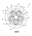
- Figure 2 provides downstream axial view of the combustor 10 shown in Figure 1 taken along line A-A.
- Various embodiments of the combustor 10 may include different numbers and arrangements of nozzles.
- the combustor 10 includes five nozzles 14 radially arranged in the top cap 18. The working fluid flows through the annular passage 28 between the flow sleeve 24 and the liner 20 (out of Figure 2 ) until it reaches the volume between the end cover 16 and top cap 18 where it reverses direction to flow through the nozzles 14 (into Figure 2 ) and into the combustion chamber 22.
- FIG. 3 shows a side perspective view of the nozzle 14 according to one embodiment of the present invention during normal operations in which a combustion flame 30 exists downstream of the nozzle 14 in the combustion chamber 22.
- the nozzle 14 generally includes a center body 32 and a shroud 34, although alternate embodiments within the scope of the present invention may include a center body 32 without a shroud 34.
- the center body 32 may connect at one end to a nozzle flange 36 so that fuel may be supplied through the flange 36 to the center body 32.
- the center body 32 generally extends along an axial centerline 38 of the nozzle 14, and the shroud 34, if present, circumferentially surrounds at least a portion of the center body 32 to define a passage 40 between the center body 32 and the shroud 34.
- the shroud 34 may include a bellmouth opening 42 or other inlet guide to evenly distribute the working fluid entering the nozzle 14 and flowing through the passage 40.
- Fuel may be injected into the passage 40 directly from the center body 32 or from swirler vanes 44 extending radially between the center body 32 and the shroud 34. In this manner, the swirler vanes 44 may impart a tangential velocity to the fuel and working fluid to evenly mix the fuel and working fluid flowing through the passage 40 before the mixture reaches the combustion chamber 22.
- the nozzle 14 further includes one or more guides 46 between the center body 32 and the shroud 34 and connected to the center body 32 downstream from the swirler vanes 44 .
- the guides 46 rotate or pivot with respect to the center body 32 and/or the shroud 34 in response to a flame holding event.
- the guides 46 may be disposed or aligned in the passage 40 at an angle acute to the axial centerline 38 of the nozzle 14. In this alignment, the guides 46 may be generally aligned with the angle of the swirler vanes 44 so as to not disturb the tangential velocity of the fuel and working fluid mixture during normal operations.
- the guides 46 rotate or pivot with respect to the center body 32 and/or shroud 34 so that the guides 46 may be generally aligned with the axial centerline 38 of the nozzle 14.
- Figures 4-9 provide various partial perspective views and diagrams of the nozzle 14 shown in Figure 3 to illustrate the structure and operation of the guides 46 in more detail.
- Figure 4 shows a partial perspective view of the nozzle 14 shown in Figure 3 with the shroud 34, guides 46, and a portion of the center body 32 removed.
- the nozzle 14 may include a plate 48 and a first set of one or more pins, rods 50, or other suitable structures that extend radially from the plate 48.
- the plate 48 may comprise any suitable material capable of continuous exposure to the anticipated temperatures inside the nozzle 14.
- the plate 48 may comprise a cylinder or a plurality of strips that extend axially inside at least a portion of the center body 32 adjacent to or proximate to an inner surface of the center body 32.
- the plate 48 may have a lower thermal coefficient of expansion than the center body 32.
- the plate 48 may be forged, rolled, or machined from nickel steel alloys such as iron and nickel that have a lower thermal coefficient of expansion than the center body 32.
- the first set of rods 50 may be fixedly or rotatably connected to the plate 48 and extend radially from the plate 48 to connect the plate 48 to the guides 46.
- Figure 5 shows another partial perspective view of the nozzle 14 shown in Figure 3 with the center body 32 again covering the plate 48.
- the first set of rods 50 extend radially from the plate 48 through slots 52 in the center body 32.
- the slots 52 thus allow the center body 32 to move axially with respect to the plate 48 and the first set of rods 50.
- the combustion flame 30 may exist inside the nozzle 14 in the passage 40 proximate to the swirler vanes 44 and/or the center body 32.
- the increased temperature associated with the combustion flame 30 proximate to the swirler vanes 44 and/or the center body 32 will increase the temperature of the center body 32 faster than and/or more than the underlying plate 48.
- the larger thermal coefficient of expansion of the center body 32 compared to that of the plate 48 will also cause the center body to expand or extend axially more than the underlying plate 48.
- the slots 52 in the center body 32 will allow the center body 32 to extend axially with respect to the plate 48 and the first set of rods 50.
- a second set of one or more pins, rods 54, or other suitable structures may extend radially from the center body 32.
- the second set of rods 54 may be fixedly or rotatably connected to the center body 32 and extend radially from the center body 32 to connect the center body 32 to the guides 46.
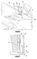
- Figures 6 and 7 show another partial perspective view and side view, respectively, of the nozzle 14 shown in Figure 3 with the center body 32 again covering the plate 48 and the guides 46 again installed over the first and second set of rods 50, 54.
- the guides 46 include a pair of recesses or hollow passages that allow the first and second rods 50, 54 to fit inside each guide 46.
- the recesses or hollow passages may extend radially through some or all of each guide 46.
- the first set of rods 50 extend radially into a guide slot 56 that provides a sliding connection between the guide 46 and the plate 48 and/or the first set of rods 50.
- the second set of rods 54 extend radially into a guide hole 58 that provides a pivotal connection between the guide 46 and the center body 32 and/or the second set of rods 54.
- the center body 32 may include a substantially flat portion 60 proximate to each guide 46.
- the substantially flat portion 60 allows each guide 46 to rotate or pivot with respect to the center body 32 without binding or creating an excessive gap between the center body 32 and the guides 46 which might create an attachment point for the combustion flame 30.
- Figure 8 provides a diagram of the guide 46 shown in Figure 3 responding to a flame holding event (shown in dashed lines).
- the guides 46 may be disposed or aligned in the passage 40 at an angle acute to the axial centerline 38 of the nozzle 14. In this alignment, the guides 46 may be generally aligned with the angle of the swirler vanes 44 so as to not disturb the tangential velocity of the fuel and working fluid mixture during normal operations.
- the combustion flame 30 increases the temperature of the center body 32 faster and/or more than the underlying plate 48.
- the larger thermal coefficient of expansion of the center body 32 compared to that of the plate 48 will also cause the center body 32 to expand or extend axially more than the underlying plate 48, causing the second set of rods 54 to move axially away from the first set of rods 50.
- the sliding connection between the guide 46 and the plate 48 or first set of rods 50 and the pivotal connection between the guide 46 and the center body 32 or second set of rods 54 causes the guide 46 to rotate or pivot with respect to the center body 32 and/or shroud 34.
- the guide 46 becomes aligned with or more closely aligned with the axial centerline 38 of the nozzle 14, thus increasing the axial velocity and/or mass flow rate of the fuel and working fluid mixture to effectively push the combustion flame 30 out of the nozzle 14.
- the increased mass flow rate of the working fluid reduces the ratio of fuel-to-working-fluid in the nozzle 14.
- the reduced fuel-to-working-fluid ratio further aids to extinguish or remove the combustion flame 30 from the nozzle 14.
- the center body 32 cools and retracts to return the guide 46 to the initial position at an angle acute to the axial centerline 38 of the nozzle 14.
- Figure 9 provides a diagram of an alternate embodiment of the guide 46 shown in Figure 3 responding to a flame holding event (shown in dashed lines).
- the first set of rods 50 extend radially into the guide hole 58
- the second set of rods 54 extend radially into the guide slot 56.
- the guide hole 58 provides a pivotal connection between the guide 46 and the plate 48 and/or the first set of rods 50
- the guide slot 56 provides a sliding connection between the guide 46 and center body 32 and/or the second set of rods 50.
- the combustion flame 30 increases the temperature of the center body 32 faster and/or more than the underlying plate 48.
- the larger thermal coefficient of expansion of the center body 32 compared to that of the plate 48 will also cause the center body 32 to expand or extend axially more than the underlying plate 48, causing the second set of rods 54 to move axially away from the first set of rods 50.
- the sliding connection between the guide 46 and the second set of rods 54 and the pivotal connection between the guide 46 and the first set of rods 50 causes the guide 46 to rotate or pivot with respect to the center body 32 and/or shroud 34.
- the guide 46 becomes aligned with or more closely aligned with the axial centerline 38 of the nozzle 14, thus increasing the axial velocity and/or mass flow rate of the fuel and working fluid mixture to effectively push the combustion flame 30 out of the nozzle 14.
- the increased mass flow rate of the working fluid reduces the ratio of fuel-to-working-fluid in the nozzle 14.
- the reduced fuel-to-working-fluid ratio further aids to extinguish or remove the combustion flame 30 from the nozzle 14.
- the center body 32 cools and retracts to return the guide 46 to the initial position at an angle acute to the axial centerline 38 of the nozzle 14.
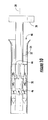
- Figure 10 provides a side perspective view of the nozzle 14 shown in Figure 3 responding to a flame holding event.
- the combustion flame 30 inside the nozzle 14 increases the temperature proximate to the guides 46.
- the combustion flame 30 increases the temperature of the center body 32, causing the center body 32 to expand more than the underlying plate 48 and rotate or pivot the guides 46 with respect to the center body 32 as previously described with respect to either Figure 8 or 9 .
- the guides 46 reduce the swirl and/or the tangential velocity of the fuel-working fluid mixture flowing through the passage 40.
- the guides 46 increase the axial velocity and/or mass flow rate of the working fluid flowing through the passage 40.
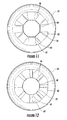
- Figure 11 provides an upstream axial view of the nozzle shown in Figure 3 during normal operations
- Figure 12 provides an upstream axial view of the nozzle shown in Figure 10 responding to a flame holding event.
- the center body 32 and/or shroud 34 are substantially flat proximate to each guide 46.
- the center body 32 includes a substantially flat portion 60 proximate to each guide 46, as previously described with respect to Figures 5 and 6 .
- the shroud 34 includes a substantially flat portion 62 proximate to each guide 46.
- the substantially flat portions 60, 62 allow each guide 46 to rotate or pivot with respect to the center body 32 and/or shroud 34 without binding or creating an excessive gap between the center body 32 and the guides 46 or between the guides 46 and the shroud 34 which might create an attachment point for the combustion flame 30.
- the nozzle 14 described and illustrated with respect to Figures 2-12 may provide a method for supplying fuel to the combustor 10.
- the method may include flowing fuel and a working fluid through the nozzle 14 at a predetermined mass flow rate and sensing a flame holding event inside the nozzle 14.
- a flame holding event inside the nozzle 14.
- the method may further include pivoting one or more guides 46 inside the nozzle 14 to increase the mass flow rate of the working fluid flowing through the nozzle 14.
- the method may further include swirling the working fluid and fuel upstream of the one or more guides 46 and/or decreasing a tangential velocity of the fuel and working fluid flowing through the nozzle 14 in response to the flame holding event.
Landscapes
- Engineering & Computer Science (AREA)
- Chemical & Material Sciences (AREA)
- Combustion & Propulsion (AREA)
- Mechanical Engineering (AREA)
- General Engineering & Computer Science (AREA)
- Pre-Mixing And Non-Premixing Gas Burner (AREA)
Abstract
Description
- The present invention generally involves a combustor nozzle. In particular, the present invention describes and enables a nozzle for a combustor and a method for responding to a flame holding event in the combustor nozzle.
- Combustors are commonly used in many forms of commercial equipment. For example, gas turbines typically include one or more combustors that mix fuel with a working fluid to generate combustion gases having a high temperature and pressure. Many combustors include nozzles that premix the fuel with the working fluid prior to combustion. Premixing the fuel with the working fluid prior to combustion allows for leaner fuel mixtures, reduces undesirable emissions, and/or improves the overall thermodynamic efficiency of the gas turbine.
- During normal combustor operations, a combustion flame exists downstream from the nozzles, typically in a combustion chamber at the exit of the nozzles. Occasionally, however, an event referred to as "flame holding" occurs in which a combustion flame exists upstream of the combustion chamber inside one or more nozzles. For example, conditions may exist in which a combustion flame exists near a fuel port in the nozzles or near an area of low flow in the nozzles. Nozzles are typically not designed to withstand the high temperatures created by a flame holding event, and flame holding may therefore cause severe damage to a nozzle in a relatively short amount of time.
- Various methods are known in the art for preventing or reducing the occurrence of flame holding. For example, flame holding is more likely to occur during the use of higher reactivity fuels or during the use of higher fuel-to-working-fluid ratios. Flame holding is also more likely to occur during operations in which the fuel-working fluid mixture flows through the nozzles at lower velocities. Combustors may therefore be designed with specific safety margins for fuel reactivity, fuel-to-working-fluid ratios, and/or fuel-working fluid mixture velocity to prevent or reduce the occurrence of flame holding. While the safety margins are effective at preventing or reducing the occurrence of flame holding, they may also result in reduced operating limits, additional maintenance, reduced operating lifetimes, and/or reduced overall thermodynamic efficiency. Therefore, a combustor nozzle and/or method for supplying fuel to the combustor in response to a flame holding event would be desirable.
- Aspects and advantages of the invention are set forth below in the following description, or may be obvious from the description, or may be learned through practice of the invention.
- In one aspect, the present invention resides in a combustor nozzle that includes a center body and a shroud circumferentially surrounding at least a portion of the center body to define a passage between the center body and the shroud. A guide between the center body and the shroud can pivot with respect to the center body.
- The present invention also includes a method for supplying fuel to a combustor. The method includes flowing a working fluid through a nozzle at a mass flow rate and flowing a fuel through the nozzle. The method further includes sensing a flame holding event inside the nozzle and pivoting a guide inside the nozzle to increase the mass flow rate of the working fluid flowing through the nozzle.
- Those of ordinary skill in the art will better appreciate the features and aspects of such embodiments, and others, upon review of the specification.
- Embodiments of the present invention will now be described, by way of example only, with reference to the accompanying drawings in which:
-
Figure 1 is a simplified cross-section of a combustor according to one embodiment of the present invention; -
Figure 2 is a downstream axial view of the combustor shown inFigure 1 taken along line A-A; -
Figure 3 is a side perspective view of a nozzle according to one embodiment of the present invention during normal operations; -
Figure 4 is a partial perspective view of the nozzle shown inFigure 3 ; -
Figure 5 is another partial perspective view of the nozzle shown inFigure 3 ; -
Figure 6 is another partial perspective view of the nozzle shown inFigure 3 ; -
Figure 7 is a side view of a guide shown inFigure 3 ; -
Figure 8 is a diagram of the guide shown inFigure 3 responding to a flame holding event; -
Figure 9 is a diagram of an alternate embodiment of the guide shown inFigure 3 responding to a flame holding event; -
Figure 10 is a side perspective view of the nozzle shown inFigure 3 responding to a flame holding event; -
Figure 11 is an upstream axial view of the nozzle shown inFigure 3 during normal operations; and -
Figure 12 is an upstream axial view of the nozzle shown inFigure 10 responding to a flame holding event. - Reference will now be made in detail to present embodiments of the invention, one or more examples of which are illustrated in the accompanying drawings. The detailed description uses numerical and letter designations to refer to features in the drawings. Like or similar designations in the drawings and description have been used to refer to like or similar parts of the invention.
- Each example is provided by way of explanation of the invention, not limitation of the invention. In fact, it will be apparent to those skilled in the art that modifications and variations can be made in the present invention without departing from the scope or spirit thereof. For instance, features illustrated or described as part of one embodiment may be used on another embodiment to yield a still further embodiment. Thus, it is intended that the present invention covers such modifications and variations as come within the scope of the appended claims and their equivalents.
- Various embodiments of the present invention include an active device that minimizes or prevents damage to a nozzle or combustor caused by flame holding. When flame holding occurs, the active device reduces the swirling of fuel and working fluid flowing through the nozzle. The reduced swirling of fuel and working fluid in the nozzle in which flame holding is occurring allows that nozzle to "borrow" additional working fluid from adjacent nozzles, thus increasing the axial velocity and/or mass flow rate of the fuel and working fluid mixture to effectively push the combustion flame out of the nozzle. In addition, assuming a constant fuel mass flow rate, the increased mass flow rate of the working fluid reduces the ratio of fuel-to-working-fluid in the nozzle. The reduced fuel-to-working-fluid ratio further aids to extinguish or remove the combustion flame from the nozzle. When flame holding no longer exists, the active device returns to its previous position to impart swirling to or allow swirling of the fuel and working fluid flowing through the nozzle.
- By responding to flame holding, the active device may provide an increase in margins before the onset of flame holding or allow for less restrictive operating limits during normal operations. For example, the ability of the active device to respond to flame holding may allow for the use of fuels with higher reactivity, less restrictive design limitations on the location of fuel injection, and fewer forced outages caused by flame holding. As a further example, the active device may allow for reduced nozzle velocities during normal operations, resulting in reduced pressure losses across the nozzle and increased thermodynamic efficiency.
-
Figure 1 shows a simplified cross-section view of acombustor 10 according to one embodiment of the present invention. Acasing 12 may surround thecombustor 10 to contain the air or working fluid flowing to thecombustor 10. As shown, thecombustor 10 may include one ormore nozzles 14 radially arranged in anend cover 16, and atop cap 18 and aliner 20 may generally define or surround acombustion chamber 22 located downstream of thenozzles 14. As used herein, the terms "upstream" and "downstream" refer to the relative location of components in a fluid pathway. For example, component A is upstream of component B if a fluid flows from component A to component B. Conversely, component B is downstream of component A if component B receives a fluid flow from component A. Aflow sleeve 24 withflow holes 26 may surround theliner 20 to define anannular passage 28 between theflow sleeve 24 and theliner 20. The air or working fluid may pass through theflow holes 26 in theflow sleeve 24 to flow along the outside of theliner 20 to provide impingement or convective cooling to theliner 20. The air or working fluid then reverses direction to flow through the one ormore nozzles 14 where it mixes with fuel before igniting in thecombustion chamber 22 to produce combustion gases having a high temperature. -
Figure 2 provides downstream axial view of thecombustor 10 shown inFigure 1 taken along line A-A. Various embodiments of thecombustor 10 may include different numbers and arrangements of nozzles. For example, in the embodiment shown inFigure 2 , thecombustor 10 includes fivenozzles 14 radially arranged in thetop cap 18. The working fluid flows through theannular passage 28 between theflow sleeve 24 and the liner 20 (out ofFigure 2 ) until it reaches the volume between theend cover 16 andtop cap 18 where it reverses direction to flow through the nozzles 14 (intoFigure 2 ) and into thecombustion chamber 22. -
Figure 3 shows a side perspective view of thenozzle 14 according to one embodiment of the present invention during normal operations in which acombustion flame 30 exists downstream of thenozzle 14 in thecombustion chamber 22. Thenozzle 14 generally includes acenter body 32 and ashroud 34, although alternate embodiments within the scope of the present invention may include acenter body 32 without ashroud 34. Thecenter body 32 may connect at one end to anozzle flange 36 so that fuel may be supplied through theflange 36 to thecenter body 32. Thecenter body 32 generally extends along anaxial centerline 38 of thenozzle 14, and theshroud 34, if present, circumferentially surrounds at least a portion of thecenter body 32 to define apassage 40 between thecenter body 32 and theshroud 34. Theshroud 34 may include abellmouth opening 42 or other inlet guide to evenly distribute the working fluid entering thenozzle 14 and flowing through thepassage 40. Fuel may be injected into thepassage 40 directly from thecenter body 32 or fromswirler vanes 44 extending radially between thecenter body 32 and theshroud 34. In this manner, theswirler vanes 44 may impart a tangential velocity to the fuel and working fluid to evenly mix the fuel and working fluid flowing through thepassage 40 before the mixture reaches thecombustion chamber 22. - As shown in
Figure 3 , thenozzle 14 further includes one ormore guides 46 between thecenter body 32 and theshroud 34 and connected to thecenter body 32 downstream from theswirler vanes 44 . Theguides 46 rotate or pivot with respect to thecenter body 32 and/or theshroud 34 in response to a flame holding event. Specifically, during normal operations when thecombustion flame 30 exists downstream of thenozzle 14 in thecombustion chamber 22, theguides 46 may be disposed or aligned in thepassage 40 at an angle acute to theaxial centerline 38 of thenozzle 14. In this alignment, theguides 46 may be generally aligned with the angle of theswirler vanes 44 so as to not disturb the tangential velocity of the fuel and working fluid mixture during normal operations. In contrast, during a flame holding event, theguides 46 rotate or pivot with respect to thecenter body 32 and/orshroud 34 so that theguides 46 may be generally aligned with theaxial centerline 38 of thenozzle 14. -
Figures 4-9 provide various partial perspective views and diagrams of thenozzle 14 shown inFigure 3 to illustrate the structure and operation of theguides 46 in more detail. Specifically,Figure 4 shows a partial perspective view of thenozzle 14 shown inFigure 3 with theshroud 34, guides 46, and a portion of thecenter body 32 removed. As shown, thenozzle 14 may include aplate 48 and a first set of one or more pins,rods 50, or other suitable structures that extend radially from theplate 48. Theplate 48 may comprise any suitable material capable of continuous exposure to the anticipated temperatures inside thenozzle 14. For example, theplate 48 may comprise a cylinder or a plurality of strips that extend axially inside at least a portion of thecenter body 32 adjacent to or proximate to an inner surface of thecenter body 32. In particular embodiments, theplate 48 may have a lower thermal coefficient of expansion than thecenter body 32. For example, theplate 48 may be forged, rolled, or machined from nickel steel alloys such as iron and nickel that have a lower thermal coefficient of expansion than thecenter body 32. The first set ofrods 50 may be fixedly or rotatably connected to theplate 48 and extend radially from theplate 48 to connect theplate 48 to theguides 46. -
Figure 5 shows another partial perspective view of thenozzle 14 shown inFigure 3 with thecenter body 32 again covering theplate 48. As shown, the first set ofrods 50 extend radially from theplate 48 throughslots 52 in thecenter body 32. Theslots 52 thus allow thecenter body 32 to move axially with respect to theplate 48 and the first set ofrods 50. For example, during a flame holding event, thecombustion flame 30 may exist inside thenozzle 14 in thepassage 40 proximate to theswirler vanes 44 and/or thecenter body 32. The increased temperature associated with thecombustion flame 30 proximate to theswirler vanes 44 and/or thecenter body 32 will increase the temperature of thecenter body 32 faster than and/or more than theunderlying plate 48. If applicable, the larger thermal coefficient of expansion of thecenter body 32 compared to that of theplate 48 will also cause the center body to expand or extend axially more than theunderlying plate 48. As a result, theslots 52 in thecenter body 32 will allow thecenter body 32 to extend axially with respect to theplate 48 and the first set ofrods 50. As further shown inFigure 5 , a second set of one or more pins,rods 54, or other suitable structures may extend radially from thecenter body 32. The second set ofrods 54 may be fixedly or rotatably connected to thecenter body 32 and extend radially from thecenter body 32 to connect thecenter body 32 to theguides 46. -
Figures 6 and 7 show another partial perspective view and side view, respectively, of thenozzle 14 shown inFigure 3 with thecenter body 32 again covering theplate 48 and theguides 46 again installed over the first and second set ofrods guides 46 include a pair of recesses or hollow passages that allow the first andsecond rods guide 46. The recesses or hollow passages may extend radially through some or all of eachguide 46. In this particular embodiment, the first set ofrods 50 extend radially into aguide slot 56 that provides a sliding connection between theguide 46 and theplate 48 and/or the first set ofrods 50. Similarly, the second set ofrods 54 extend radially into aguide hole 58 that provides a pivotal connection between theguide 46 and thecenter body 32 and/or the second set ofrods 54. Notably, as shown most clearly inFigures 5 and6 , and as will be explained in more detail with respect toFigures 11 and 12 , thecenter body 32 may include a substantiallyflat portion 60 proximate to eachguide 46. The substantiallyflat portion 60, if present, allows eachguide 46 to rotate or pivot with respect to thecenter body 32 without binding or creating an excessive gap between thecenter body 32 and theguides 46 which might create an attachment point for thecombustion flame 30. -
Figure 8 provides a diagram of theguide 46 shown inFigure 3 responding to a flame holding event (shown in dashed lines). During normal operations in which thecombustion flame 30 exists downstream of thenozzle 14 in thecombustion chamber 22, theguides 46 may be disposed or aligned in thepassage 40 at an angle acute to theaxial centerline 38 of thenozzle 14. In this alignment, theguides 46 may be generally aligned with the angle of theswirler vanes 44 so as to not disturb the tangential velocity of the fuel and working fluid mixture during normal operations. During a flame holding event, thecombustion flame 30 increases the temperature of thecenter body 32 faster and/or more than theunderlying plate 48. If applicable, the larger thermal coefficient of expansion of thecenter body 32 compared to that of theplate 48 will also cause thecenter body 32 to expand or extend axially more than theunderlying plate 48, causing the second set ofrods 54 to move axially away from the first set ofrods 50. The sliding connection between theguide 46 and theplate 48 or first set ofrods 50 and the pivotal connection between theguide 46 and thecenter body 32 or second set ofrods 54 causes theguide 46 to rotate or pivot with respect to thecenter body 32 and/orshroud 34. As a result of the rotation, theguide 46 becomes aligned with or more closely aligned with theaxial centerline 38 of thenozzle 14, thus increasing the axial velocity and/or mass flow rate of the fuel and working fluid mixture to effectively push thecombustion flame 30 out of thenozzle 14. In addition, assuming a constant fuel mass flow rate, the increased mass flow rate of the working fluid reduces the ratio of fuel-to-working-fluid in thenozzle 14. The reduced fuel-to-working-fluid ratio further aids to extinguish or remove thecombustion flame 30 from thenozzle 14. When the flame holding event no longer exists, thecenter body 32 cools and retracts to return theguide 46 to the initial position at an angle acute to theaxial centerline 38 of thenozzle 14. -
Figure 9 provides a diagram of an alternate embodiment of theguide 46 shown inFigure 3 responding to a flame holding event (shown in dashed lines). In this particular embodiment, the first set ofrods 50 extend radially into theguide hole 58, and the second set ofrods 54 extend radially into theguide slot 56. As a result, theguide hole 58 provides a pivotal connection between theguide 46 and theplate 48 and/or the first set ofrods 50, and theguide slot 56 provides a sliding connection between theguide 46 andcenter body 32 and/or the second set ofrods 50. During a flame holding event, thecombustion flame 30 increases the temperature of thecenter body 32 faster and/or more than theunderlying plate 48. If applicable, the larger thermal coefficient of expansion of thecenter body 32 compared to that of theplate 48 will also cause thecenter body 32 to expand or extend axially more than theunderlying plate 48, causing the second set ofrods 54 to move axially away from the first set ofrods 50. The sliding connection between theguide 46 and the second set ofrods 54 and the pivotal connection between theguide 46 and the first set ofrods 50 causes theguide 46 to rotate or pivot with respect to thecenter body 32 and/orshroud 34. As a result of the rotation, theguide 46 becomes aligned with or more closely aligned with theaxial centerline 38 of thenozzle 14, thus increasing the axial velocity and/or mass flow rate of the fuel and working fluid mixture to effectively push thecombustion flame 30 out of thenozzle 14. In addition, assuming a constant fuel mass flow rate, the increased mass flow rate of the working fluid reduces the ratio of fuel-to-working-fluid in thenozzle 14. The reduced fuel-to-working-fluid ratio further aids to extinguish or remove thecombustion flame 30 from thenozzle 14. When the flame holding event no longer exists, thecenter body 32 cools and retracts to return theguide 46 to the initial position at an angle acute to theaxial centerline 38 of thenozzle 14. -
Figure 10 provides a side perspective view of thenozzle 14 shown inFigure 3 responding to a flame holding event. As shown, thecombustion flame 30 inside thenozzle 14 increases the temperature proximate to theguides 46. Specifically, thecombustion flame 30 increases the temperature of thecenter body 32, causing thecenter body 32 to expand more than theunderlying plate 48 and rotate or pivot theguides 46 with respect to thecenter body 32 as previously described with respect to eitherFigure 8 or 9 . As theguides 46 become more aligned with theaxial centerline 38 of thenozzle 14, theguides 46 reduce the swirl and/or the tangential velocity of the fuel-working fluid mixture flowing through thepassage 40. Alternately, or in addition, theguides 46 increase the axial velocity and/or mass flow rate of the working fluid flowing through thepassage 40. Since the swirl angle induced by theswirler vanes 44 will remain approximately the same upstream of theguides 46 and the mass flow increases, the combined velocity magnitude (axial and tangential) of the working fluid increases. Assuming a constant fuel flow, the fuel-to-working-fluid ratio thus decreases. It is believed that any or all of these effects contribute to blowing thecombustion flame 30 out of thenozzle 14 and back into thecombustion chamber 22. When the flame holding no longer exists inside thenozzle 14, the temperature of thecenter body 32 decreases, causing theguides 46 to rotate or pivot with respect to thecenter body 32 and therefore again becoming aligned with the swirling fuel and working fluid mixture. -
Figure 11 provides an upstream axial view of the nozzle shown inFigure 3 during normal operations, andFigure 12 provides an upstream axial view of the nozzle shown inFigure 10 responding to a flame holding event. As shown in each figure, thecenter body 32 and/orshroud 34 are substantially flat proximate to eachguide 46. Specifically, thecenter body 32 includes a substantiallyflat portion 60 proximate to eachguide 46, as previously described with respect toFigures 5 and6 . Similarly, theshroud 34 includes a substantiallyflat portion 62 proximate to eachguide 46. The substantiallyflat portions guide 46 to rotate or pivot with respect to thecenter body 32 and/orshroud 34 without binding or creating an excessive gap between thecenter body 32 and theguides 46 or between theguides 46 and theshroud 34 which might create an attachment point for thecombustion flame 30. - The
nozzle 14 described and illustrated with respect toFigures 2-12 may provide a method for supplying fuel to thecombustor 10. The method may include flowing fuel and a working fluid through thenozzle 14 at a predetermined mass flow rate and sensing a flame holding event inside thenozzle 14. For example, an increase in the temperature in thepassage 40 or proximate to theguides 46,swirler vanes 44, and/orcenter body 32 may provide a reliable indication of the presence of a flame holding event inside thenozzle 14. The method may further include pivoting one ormore guides 46 inside thenozzle 14 to increase the mass flow rate of the working fluid flowing through thenozzle 14. In particular embodiments, the method may further include swirling the working fluid and fuel upstream of the one ormore guides 46 and/or decreasing a tangential velocity of the fuel and working fluid flowing through thenozzle 14 in response to the flame holding event. - This written description uses examples to disclose the invention, including the best mode, and also to enable any person skilled in the art to practice the invention, including making and using any devices or systems and performing any incorporated methods. The patentable scope of the invention is defined by the claims, and may include other examples that occur to those skilled in the art. Such other examples are intended to be within the scope of the claims if they include structural elements that do not differ from the literal language of the claims, or if they include equivalent structural elements with insubstantial differences from the literal languages of the claims.
Claims (13)
- A combustor nozzle (14), comprising:a. a center body (32);b. a shroud (34) circumferentially surrounding at least a portion of the center body (32) to define a passage (40) between the center body (32) and the shroud (34); andc. a guide (46) between the center body (32) and the shroud (34), wherein the guide (46) can pivot with respect to the center body (32).
- The combustor nozzle (14) as in claim 1, wherein the center body (32) is substantially flat proximate to the guide (46).
- The combustor nozzle (14) as in claim 1 or 2, wherein the shroud (34) is substantially flat proximate to the guide (46).
- The combustor nozzle (14) as in any of claims 1 to 3, further comprising a plate (48) extending inside at least a portion of the center body (32).
- The combustor nozzle (14) as in claim 4, further comprising a pivotal connection between the guide (46) and at least one of the plate (48) or the center body (32).
- The combustor nozzle (14) as in claim 4 or 5, further comprising a sliding connection between the guide (46) and at least one of the plate (48) or the center body (32).
- The combustor nozzle (14) as in any preceding claim, wherein the guide (46) is aligned at an acute angle to a longitudinal axis of the center body (32).
- The combustor nozzle (14) as in any preceding claim, further comprising a swirler vane (44) upstream of the guide (46).
- The combustor nozzle as in any of claims 4 to 8, wherein the plate has a thermal coefficient of expansion that is less than the thermal coefficient of expansion of the center body.
- A method for supplying fuel to a combustor (10), comprising:a. flowing a working fluid through a nozzle (14) at a mass flow rate;b. flowing a fuel through the nozzle (14);c. sensing a flame holding event inside the nozzle (14); andd. pivoting a guide (46) inside the nozzle (14) to increase the mass flow rate of the working fluid flowing through the nozzle (14).
- The method as in claim 10, further comprising swirling the working fluid and fuel upstream of the guide (46).
- The method as in claim 10 or 11, further comprising decreasing a tangential velocity of the fuel and working fluid flowing through the nozzle (14).
- The method as in any of claims 10 to 12, further comprising increasing an axial velocity of the fuel and working fluid flowing through the nozzle (14).
Applications Claiming Priority (1)
| Application Number | Priority Date | Filing Date | Title |
|---|---|---|---|
| US13/083,769 US8307660B2 (en) | 2011-04-11 | 2011-04-11 | Combustor nozzle and method for supplying fuel to a combustor |
Publications (2)
| Publication Number | Publication Date |
|---|---|
| EP2511607A2 true EP2511607A2 (en) | 2012-10-17 |
| EP2511607A3 EP2511607A3 (en) | 2013-12-04 |
Family
ID=45954478
Family Applications (1)
| Application Number | Title | Priority Date | Filing Date |
|---|---|---|---|
| EP12163134.5A Withdrawn EP2511607A3 (en) | 2011-04-11 | 2012-04-04 | Combustor Nozzle And Method For Supplying Fuel To A Combustor |
Country Status (3)
| Country | Link |
|---|---|
| US (1) | US8307660B2 (en) |
| EP (1) | EP2511607A3 (en) |
| CN (1) | CN102798151A (en) |
Cited By (1)
| Publication number | Priority date | Publication date | Assignee | Title |
|---|---|---|---|---|
| EP2933560A1 (en) * | 2014-04-17 | 2015-10-21 | Alstom Technology Ltd | Method for premixing air with a gaseous fuel and burner arrangement for conducting said method |
Families Citing this family (9)
| Publication number | Priority date | Publication date | Assignee | Title |
|---|---|---|---|---|
| DE102009045950A1 (en) * | 2009-10-23 | 2011-04-28 | Man Diesel & Turbo Se | swirl generator |
| US9395084B2 (en) * | 2012-06-06 | 2016-07-19 | General Electric Company | Fuel pre-mixer with planar and swirler vanes |
| KR102129052B1 (en) * | 2013-11-12 | 2020-07-02 | 한화에어로스페이스 주식회사 | Swirler assembly |
| US9528702B2 (en) * | 2014-02-21 | 2016-12-27 | General Electric Company | System having a combustor cap |
| US9528704B2 (en) | 2014-02-21 | 2016-12-27 | General Electric Company | Combustor cap having non-round outlets for mixing tubes |
| CN106524159B (en) * | 2016-12-28 | 2018-11-30 | 安徽诚铭热能技术有限公司 | Spinning disk, turbulent burner and its manufacturing method |
| US11530617B2 (en) | 2020-10-26 | 2022-12-20 | Antheon Research, Inc. | Gas turbine propulsion system |
| US11002146B1 (en) | 2020-10-26 | 2021-05-11 | Antheon Research, Inc. | Power generation system |
| US12281795B1 (en) * | 2024-03-11 | 2025-04-22 | Rtx Corporation | Cluster of swirled mini-mixers for fuel-staged, axially staged combustion |
Family Cites Families (10)
| Publication number | Priority date | Publication date | Assignee | Title |
|---|---|---|---|---|
| GB1410923A (en) * | 1971-12-15 | 1975-10-22 | Hotwork Ltd | Fluid fuel burners |
| JPS577951Y2 (en) * | 1976-09-22 | 1982-02-16 | ||
| IT1248305B (en) * | 1990-05-29 | 1995-01-05 | Gen Electric | AUTOMATIC VARIABLE GEOMETRY VORTIC FORMER |
| US5207558A (en) | 1991-10-30 | 1993-05-04 | The United States Of America As Represented By The Secretary Of The Air Force | Thermally actuated vane flow control |
| US5603906A (en) * | 1991-11-01 | 1997-02-18 | Holman Boiler Works, Inc. | Low NOx burner |
| DE50205914D1 (en) | 2002-08-26 | 2006-04-27 | Borgwarner Inc | Adjustable guide grid for a turbine unit |
| AU2003206001A1 (en) | 2003-02-19 | 2004-09-09 | Honeywell International Inc. | Nozzle device for a turbocharger and associated control method |
| US6993916B2 (en) * | 2004-06-08 | 2006-02-07 | General Electric Company | Burner tube and method for mixing air and gas in a gas turbine engine |
| US20110005189A1 (en) * | 2009-07-08 | 2011-01-13 | General Electric Company | Active Control of Flame Holding and Flashback in Turbine Combustor Fuel Nozzle |
| US8024932B1 (en) * | 2010-04-07 | 2011-09-27 | General Electric Company | System and method for a combustor nozzle |
-
2011
- 2011-04-11 US US13/083,769 patent/US8307660B2/en not_active Expired - Fee Related
-
2012
- 2012-04-04 EP EP12163134.5A patent/EP2511607A3/en not_active Withdrawn
- 2012-04-11 CN CN201210115421XA patent/CN102798151A/en active Pending
Non-Patent Citations (1)
| Title |
|---|
| None |
Cited By (2)
| Publication number | Priority date | Publication date | Assignee | Title |
|---|---|---|---|---|
| EP2933560A1 (en) * | 2014-04-17 | 2015-10-21 | Alstom Technology Ltd | Method for premixing air with a gaseous fuel and burner arrangement for conducting said method |
| US9810432B2 (en) | 2014-04-17 | 2017-11-07 | Ansaldo Energia Switzerland AG | Method for premixing air with a gaseous fuel and burner arrangement for conducting said method |
Also Published As
| Publication number | Publication date |
|---|---|
| CN102798151A (en) | 2012-11-28 |
| EP2511607A3 (en) | 2013-12-04 |
| US20120255310A1 (en) | 2012-10-11 |
| US8307660B2 (en) | 2012-11-13 |
Similar Documents
| Publication | Publication Date | Title |
|---|---|---|
| US8307660B2 (en) | Combustor nozzle and method for supplying fuel to a combustor | |
| US8024932B1 (en) | System and method for a combustor nozzle | |
| EP2559946B1 (en) | System and method for reducing combustion dynamics in a combustor | |
| EP2728262B1 (en) | A combustor cap assembly | |
| JP5530131B2 (en) | Flame-resistant fuel / air premixer for gas turbine combustors | |
| EP2220437B1 (en) | Impingement cooled can combustor | |
| EP2728263B1 (en) | A combustor | |
| EP2584266B1 (en) | Combustor and method for conditioning flow through a combustor | |
| JP6118024B2 (en) | Combustor nozzle and method of manufacturing combustor nozzle | |
| JP6037338B2 (en) | Gas turbine combustor | |
| JP2010223577A (en) | Swirl, method for preventing backfire in burner equipped with at least one swirler, and burner | |
| JP2010223577A6 (en) | Swirl, method for preventing backfire in burner equipped with at least one swirler, and burner | |
| US8579211B2 (en) | System and method for enhancing flow in a nozzle | |
| JP2012057930A (en) | Apparatus and method for mixing fuel in gas turbine nozzle | |
| EP3187783A1 (en) | Fuel nozzle assembly having a premix flame stabilizer | |
| JP2010223577A5 (en) | ||
| EP3211318A2 (en) | Gas-only cartridge for a premix fuel nozzle | |
| EP2613089B1 (en) | Combustor and method for distributing fuel in the combustor | |
| EP2868972B1 (en) | Gas turbine combustor | |
| EP3220049B1 (en) | Gas turbine combustor having liner cooling guide vanes | |
| JP4477039B2 (en) | Combustion device for gas turbine engine | |
| EP2532964A2 (en) | System for conditioning flow through a combustor | |
| US12385641B1 (en) | Combustor for a gas turbine engine | |
| US20260022836A1 (en) | Combustor for a gas turbine engine | |
| US20120305677A1 (en) | System for conditioning flow through a nozzle |
Legal Events
| Date | Code | Title | Description |
|---|---|---|---|
| PUAI | Public reference made under article 153(3) epc to a published international application that has entered the european phase |
Free format text: ORIGINAL CODE: 0009012 |
|
| AK | Designated contracting states |
Kind code of ref document: A2 Designated state(s): AL AT BE BG CH CY CZ DE DK EE ES FI FR GB GR HR HU IE IS IT LI LT LU LV MC MK MT NL NO PL PT RO RS SE SI SK SM TR |
|
| AX | Request for extension of the european patent |
Extension state: BA ME |
|
| PUAL | Search report despatched |
Free format text: ORIGINAL CODE: 0009013 |
|
| AK | Designated contracting states |
Kind code of ref document: A3 Designated state(s): AL AT BE BG CH CY CZ DE DK EE ES FI FR GB GR HR HU IE IS IT LI LT LU LV MC MK MT NL NO PL PT RO RS SE SI SK SM TR |
|
| AX | Request for extension of the european patent |
Extension state: BA ME |
|
| RIC1 | Information provided on ipc code assigned before grant |
Ipc: F23R 3/28 20060101ALI20131028BHEP Ipc: F23C 7/00 20060101AFI20131028BHEP Ipc: F23D 14/70 20060101ALI20131028BHEP Ipc: F23R 3/14 20060101ALI20131028BHEP |
|
| STAA | Information on the status of an ep patent application or granted ep patent |
Free format text: STATUS: THE APPLICATION IS DEEMED TO BE WITHDRAWN |
|
| 18D | Application deemed to be withdrawn |
Effective date: 20140605 |