EP2511479A2 - Annulus filler system - Google Patents
Annulus filler system Download PDFInfo
- Publication number
- EP2511479A2 EP2511479A2 EP12160837A EP12160837A EP2511479A2 EP 2511479 A2 EP2511479 A2 EP 2511479A2 EP 12160837 A EP12160837 A EP 12160837A EP 12160837 A EP12160837 A EP 12160837A EP 2511479 A2 EP2511479 A2 EP 2511479A2
- Authority
- EP
- European Patent Office
- Prior art keywords
- sleeve
- foot
- disc
- annulus filler
- annulus
- Prior art date
- Legal status (The legal status is an assumption and is not a legal conclusion. Google has not performed a legal analysis and makes no representation as to the accuracy of the status listed.)
- Granted
Links
Images


Classifications
-
- F—MECHANICAL ENGINEERING; LIGHTING; HEATING; WEAPONS; BLASTING
- F01—MACHINES OR ENGINES IN GENERAL; ENGINE PLANTS IN GENERAL; STEAM ENGINES
- F01D—NON-POSITIVE DISPLACEMENT MACHINES OR ENGINES, e.g. STEAM TURBINES
- F01D5/00—Blades; Blade-carrying members; Heating, heat-insulating, cooling or antivibration means on the blades or the members
- F01D5/30—Fixing blades to rotors; Blade roots ; Blade spacers
-
- F—MECHANICAL ENGINEERING; LIGHTING; HEATING; WEAPONS; BLASTING
- F01—MACHINES OR ENGINES IN GENERAL; ENGINE PLANTS IN GENERAL; STEAM ENGINES
- F01D—NON-POSITIVE DISPLACEMENT MACHINES OR ENGINES, e.g. STEAM TURBINES
- F01D11/00—Preventing or minimising internal leakage of working-fluid, e.g. between stages
- F01D11/005—Sealing means between non relatively rotating elements
- F01D11/006—Sealing the gap between rotor blades or blades and rotor
- F01D11/008—Sealing the gap between rotor blades or blades and rotor by spacer elements between the blades, e.g. independent interblade platforms
-
- F—MECHANICAL ENGINEERING; LIGHTING; HEATING; WEAPONS; BLASTING
- F01—MACHINES OR ENGINES IN GENERAL; ENGINE PLANTS IN GENERAL; STEAM ENGINES
- F01D—NON-POSITIVE DISPLACEMENT MACHINES OR ENGINES, e.g. STEAM TURBINES
- F01D5/00—Blades; Blade-carrying members; Heating, heat-insulating, cooling or antivibration means on the blades or the members
- F01D5/12—Blades
- F01D5/28—Selecting particular materials; Particular measures relating thereto; Measures against erosion or corrosion
-
- F—MECHANICAL ENGINEERING; LIGHTING; HEATING; WEAPONS; BLASTING
- F01—MACHINES OR ENGINES IN GENERAL; ENGINE PLANTS IN GENERAL; STEAM ENGINES
- F01D—NON-POSITIVE DISPLACEMENT MACHINES OR ENGINES, e.g. STEAM TURBINES
- F01D5/00—Blades; Blade-carrying members; Heating, heat-insulating, cooling or antivibration means on the blades or the members
- F01D5/30—Fixing blades to rotors; Blade roots ; Blade spacers
- F01D5/3092—Protective layers between blade root and rotor disc surfaces, e.g. anti-friction layers
-
- F—MECHANICAL ENGINEERING; LIGHTING; HEATING; WEAPONS; BLASTING
- F05—INDEXING SCHEMES RELATING TO ENGINES OR PUMPS IN VARIOUS SUBCLASSES OF CLASSES F01-F04
- F05D—INDEXING SCHEME FOR ASPECTS RELATING TO NON-POSITIVE-DISPLACEMENT MACHINES OR ENGINES, GAS-TURBINES OR JET-PROPULSION PLANTS
- F05D2300/00—Materials; Properties thereof
- F05D2300/60—Properties or characteristics given to material by treatment or manufacturing
- F05D2300/603—Composites; e.g. fibre-reinforced
Definitions
- the present invention relates to an annulus filler system for bridging the gap between adjacent blades of a gas turbine engine stage.
- a ducted fan gas turbine engine generally indicated at 10 has a principal and rotational axis X-X.
- the engine comprises, in axial flow series, an air intake 11, a propulsive fan 12, an intermediate pressure compressor 13, a high-pressure compressor 14, combustion equipment 15, a high-pressure turbine 16, and intermediate pressure turbine 17, a low-pressure turbine 18 and a core engine exhaust nozzle 19.
- a nacelle 21 generally surrounds the engine 10 and defines the intake 11, a bypass duct 22 and a bypass exhaust nozzle 23.
- the gas turbine engine 10 works in a conventional manner so that air entering the intake 11 is accelerated by the fan 12 to produce two air flows: a first air flow A into the intermediate pressure compressor 13 and a second air flow B which passes through the bypass duct 22 to provide propulsive thrust.
- the intermediate pressure compressor 13 compresses the air flow A directed into it before delivering that air to the high pressure compressor 14 where further compression takes place.
- the compressed air exhausted from the high-pressure compressor 14 is directed into the combustion equipment 15 where it is mixed with fuel and the mixture combusted.
- the resultant hot combustion products then expand through, and thereby drive the high, intermediate and low-pressure turbines 16, 17, 18 before being exhausted through the nozzle 19 to provide additional propulsive thrust.
- the high, intermediate and low-pressure turbines respectively drive the high and intermediate pressure compressors 14, 13 and the fan 12 by suitable interconnecting shafts.
- a compressor rotor stage comprises a plurality of radially extending blades mounted on a disc.
- the blades are mounted on the disc by inserting a root portion of the blade in a complementary retention groove in the outer face of the disc periphery.
- annulus fillers can be used to bridge the spaces between adjacent blades.
- a seal between the annulus fillers and the adjacent fan blades is also provided by resilient strips bonded to the annulus fillers adjacent the fan blades.
- Annulus fillers of this type are commonly used in the fan stage.
- the fillers may be manufactured from relatively lightweight materials and, in the event of damage, may be replaced independently of the blades
- annulus fillers with features for removably attaching them to the rotor disc.
- An annulus filler may be provided with a hook member at its axially rear end, the hook member sliding into engagement with part of the rotor disc and/or a component located axially behind the rotor assembly, for example a rear fan air seal.
- a front attachment disc which is fastened over the fronts of all the annulus fillers located around the rotor disc.
- US 4655687 proposes an annulus filler that can be fitted to the rotor disc in a radial direction of the disc.
- the annulus filler that has a salient foot that is shaped similarly to re-entrant grooves formed in the disc rim between pairs of adjacent blades. The foot is proportioned so as to pass radially of the disc through the neck of a respective groove. Wedges positioned between opposing walls of the grooves and respective feet then prevent withdrawal of the feet in a direction radially outwardly of the disc.
- US6132175 proposes a compliant sleeve for ceramic turbine blades that addresses irregularities between the ceramic blade dovetail and the disc.
- the sleeve also acts as a compliant member to reduce frettage.
- An aim of the present invention is to provide annulus fillers that are suitable for use with composite blades, and in particular carbon fibre reinforced plastic (CFRP) blades.
- CFRP carbon fibre reinforced plastic
- a first aspect of the present invention provides an annulus filler system for bridging the gap between two adjacent blades attached to a rim of the rotor disc of a gas turbine engine, the system including:
- the composite material foot (and typically other composite material parts) of the filler can reduce the filler mass.
- the sleeve enables a filler having at least a composite material foot to be used with, for example, a metal disc by preventing galvanic corrosion between the foot and the disc.
- the sleeve can also provide a suitable interface between a relatively soft filler foot and a relatively hard disc.
- the annulus filler system may have any one or, to the extent that they are compatible, any combination of the following optional features.
- the disc is a metal disc.
- the foot is formed of fibre-reinforced plastic, e.g. carbon-fibre reinforced plastic. Galvanic corrosion can be a particular problem between carbon fibres and metals.
- the foot may be proportioned to pass through the neck of the groove in a radial direction on installation of the filler.
- the sleeve can then be proportioned to prevent withdrawal of the foot through the neck, after installation of the filler, in a radially outward direction of the disc.
- the groove extends in substantially an axial direction of the engine, i.e. substantially aligned with retention slots in the disc rim for retaining the blades.
- the groove may follow a straight or a curved path from the front to the rear of the disc.
- the walls of the groove may be parallel, or the groove may taper from one end to another.
- the sleeve may have a stop which engages with the rim to prevent the sleeve from sliding beyond its intended location position.
- the sleeve wraps around the foot to extend from one side of the neck to the other.
- the sleeve may be configured to protrude past the neck of the groove and to flare outwardly away from the support body. In this way, free edges of the sleeve outside the groove can be kept away from the support body of the annulus filler, avoiding damage to the support body from those edges.
- the annulus filler may further have sealing strips along the edges of the lid to seal to the adjacent blades.
- the sleeve may have a layer of ballotinis within the galvanic isolation layer.
- the ballotinis can ensure a minimum thickness for the galvanic isolation layer.
- the layer of ballotinis may be at the inner surface of the sleeve and contact, in use, the foot.
- the ballotinis which can be formed e.g. of glass or resin, are generally effective galvanic isolators and can reliably space the foot from other parts of the sleeve which offer less galvanic corrosion protection.
- the ballotinis may be completely or partially embedded in a matrix such as a layer of resin or an adhesive. For example, with partial embedding, a portion of each ballotini may be proud of the matrix such that only the ballotinis and not the matrix contact the foot. This can help to improve the galvanic isolation of the foot by reducing the foot surface area in contact with the sleeve.
- a galvanic isolation layer can be provided by: a layer of glass fibre in a non-conductive matrix; a glass layer formed or fused onto the surface of the sleeve; or a paint layer or coating. Whichever type of layer is adopted, it should be resilient to direct loading, for example from forced rocking of the annulus filler by the blades, or from foreign objects impacting the airflow surface of the lid of the filler.
- the sleeve may be bonded to the foot after the sleeve is located in the gap, e.g. by a resin or adhesive.
- a resin or adhesive For example, a cyno-acrylic adhesive may be applied to the inner surface of the sleeve before location of the sleeve. The adhesive then cures after location of the sleeve in the presence of water to bond the sleeve to the foot.
- Such adhesives are relatively strong in tension, helping the sleeve to remain in location in use, but relatively weak in shear, allowing the sleeve to be removed for servicing, inspection or maintenance.
- the ballotinis may be embedded in the resin or adhesive, such as a paste adhesive.
- a paste adhesive e.g.
- a nitrile phenolic adhesive or a two part catalytic set epoxy adhesive such as 3M Scotch-Weld 2216 TM or a thermoset epoxy adhesive such as 3M Scotch-Weld AF500 TM
- 3M Scotch-Weld AF500 TM can advantageously act as a damper between the foot and the sleeve. It can also act as a filler to accommodate manufacturing tolerances between the foot and the sleeve, and can help to exclude moisture from the interface between the foot and the sleeve.
- the foot may have an outer layer of glass fibre, e.g. woven or braided glass fibre. Such a layer can also improve the galvanic isolation of the foot.
- the sleeve may have an anti-frettage coating at its outer surface, the anti-frettage coating contacting, in use, the disc.
- the anti-frettage coating may be formed of molybdenum disulphide, tungsten disulphide or polytetrafluoroethylene.
- the anti-frettage coating may be selectively located at positions on the outer surface most susceptible to fretting.
- the anti-frettage coating may be applied e.g. by thermal spraying, PVD or ebPVD, as appropriate.
- the sleeve may have a main body, for example with the galvanic isolation layer on an inner surface of the body and/or an anti-frettage coating on its outer surface.
- the main body can be metallic.For example, it can be formed from a conventional titanium alloy, or a high damping alloy such as a titanium-niobium alloy or a titanium-hafnium alloy of the type known as gum metal. A damping alloy can help to resist shear motion at the sleeve-disc interface and hence to reduce fretting. Other metallic or non-metallic materials can be used to form the main body of the sleeve depending on, loading, and filler foot interaction required.
- the foot has a dovetail-shaped cross-section.
- the groove can be correspondingly dovetail-shaped in cross-section.
- the foot may have a circular cross-section, e.g. on a stalk extending from the support body.
- the lid is formed from fibre-reinforced plastic, e.g. CFRP.
- the support body may have a pair of side walls, each side wall joining a respective edge of the lid to the foot to give the support body a V-shaped cross-section. As the V-shaped cross-section supports the lid at its edges, the edges of the lid are less likely to disintegrate during an extreme event.
- the side walls are formed from fibre-reinforced plastic, e.g. CFRP.
- a cavity formed by the lid and the two side walls contains a foam core, e.g. formed from a plastic material such as a foamed resin or syntactic foam.
- the foam core can provide a stiffer filler structure, more able to retain its shape.
- the cavity may contain a chopped fibre composite, e.g. a chopped carbon fibre in a resin such as epoxy.
- An annulus filler in which the lid, support body and foot are all formed of composite or plastic material can be made very lightweight, helping to increase the efficiency of the engine.
- a second aspect of the present invention provides a sleeve of the annulus filler system according to the first aspect.
- a third aspect of the present invention provides a rotor assembly according to the first aspect.
- a fourth aspect of the present invention provides a rotor assembly for a gas turbine engine including:
- the rotor disc is a fan disc.
- the blades may be formed of composite material.
- FIGS 2 and 3 show schematically perspective views of respectively an annulus filler 30 and a retention sleeve 35 of an annulus filler system according to an embodiment of the present invention.
- the filler has a lid 31 which, in use, extends between two adjacent composite fan blades, and a support body 32 extending beneath the lid and terminating in an elongate foot 33.
- the support body is formed by two side walls 34 which join to the lid along respective edges of the lid and meet at the foot to give the body a V-shaped cross-section.
- the foot has a dovetail cross-section, e.g. with about 55° flank angles.
- the retention sleeve 35 is shaped to wrap around the foot 33.
- Figure 4 shows schematically an end on view of the annulus filler 30 and the retention sleeve 35 when fitted to a groove 36 of a metal rotor disc
- Figure 5 shows schematically a side view on the engine axial line of the fitted filler and sleeve.
- the groove is dovetail-shaped in cross-section, like the foot 33, and is located on the disc rim in the outside face of post 38 formed between slots 39 which hold the fan blades 40 to the disc.
- An alternative arrangement has a circular foot cross-section and a correspondingly circular groove cross-section.
- the groove may follow a straight or a curved path from the front to the rear of the disc, and the sleeve is correspondingly straight or curved.
- the annulus filler is positioned outwardly of the groove and then moved radially inwardly.
- the widest part of the foot is proportioned to pass through the neck 41 of the groove so that the foot can be located completely in the groove. This enables fitting annulus fillers between blades that are shaped such that the fillers cannot be slid into position along the groove in a generally rearward direction of the engine.
- the retention sleeve 35 is slidingly located into the gap formed between the groove and the foot.
- the sleeve wraps around the foot and protrudes past the neck of the groove to flare outwardly away from the support body so that the free edges 42 of the sleeve are kept away from the support body 32. This helps to prevent the free edges from damaging the support body or posts 38 if there is relative movement between the sleeve and the body.
- a stop 43 at the end of the sleeve 35 prevents the sleeve from sliding in one direction out of the groove 36. Sliding of the sleeve in the other direction can be prevented by a support ring 44 fitted to the face of the disc 37 after location of the sleeve.
- the stop and support ring can ensure repeatable axial positioning and retention of the sleeve.
- the lid 31 of the annulus filler 30 When fitted, the lid 31 of the annulus filler 30 forms a continuous airflow surface along with a nose cone 45 at the front of the lid and a seal ring 46 at the rear of the lid. Sealing strips 47 extending along the edges of the lid seal the lid to the sides of the adjacent blades 40.
- the foot 33 and groove 36 retention system can distribute loads over the entire axial length of the filler 30.
- the weight of the filler can be reduced, for example, by forming the lid 31, the side walls 34 and the foot 33 from carbon fibre reinforced plastic.
- the lid may be secured to the side walls by stitching through laminate layers, which can help to stiffen the edges of the lid, thereby providing a secure base for the sealing strips 47.
- the cavity formed by the lid and side walls can be filled with a foam core 48 or have an internal lattice structure, which can provide a lightweight resilient support to the lid and side walls. Such support can absorb impact energy and help the lid and side walls to retain their shape after impact deformation.
- the filler may be produced by foaming the material of the core within a pre-preg envelope of the lid, side walls and foot, and then completing the lid, side walls and foot by resin transfer moulding.
- the basic filler structure can be formed as a pre-preg tube by 3D Braiding or 3D weaving carbon fibres.
- An outer layer of glass fibre, e.g. woven or braided glass fibre can be applied to the foot to improve the galvanic isolation of the foot.
- a former can be placed inside the preform, which is then resin transfer moulded.
- the foam core is foamed in situ in the cavity and the surfaces sealed.
- the lid may have a coating, such as an elastomer (e.g. polyurethane), applied to resist sand, debris, and tool drops. Typically the coating would be applied as a sheet or sprayed on.
- a more sophisticated 3D braided or woven structure can be made to provide internal struts or lattice within the cavity, in which case more than one former may be required during moulding.
- FIG. 6 shows schematically a transverse cross-section through the sleeve 35.
- the inner surface of the sleeve is covered with a layer of ballotinis 48.
- the ballontinis are partially or fully embedded in a layer of resin or adhesive 49 such that the ballotinis ensure a minimum thickness for the galvanic isolation layer formed by the ballotinis and the resin.
- the galvanic isolation layer isolates the carbon fibres in the foot from the rest of the sleeve and the metal disc 37. If the ballotinis are partially embedded in the resin, only the proud portions of the ballotinis may make contact, in use, with the foot 33. This can reduce the contact area of the foot with the sleeve.
- a paste adhesive may be used to fill the gaps between the ballotinis and provide a loose bond to the filler foot. Such a paste adhesive is preferably chosen to provide damping to the filler foot.
- Two sizes of ballotinis may be used: the larger size being only partially embedded and having proud portions penetrating to an extent into the surface of the foot and thereby improving the locking between the foot and the sleeve, and the smaller size being fully embedded with the resin or paste adhesive to ensure a minimum thickness for the galvanic isolation layer.
- the sleeve has a main body 50 which carries the layer of ballotinis 48 on its inner surface.
- the main body can be formed, for example, of a conventional titanium alloy, or a high damping alloy such as a titanium-niobium-oxygen alloy or a titanium-hafnium-oxygen alloy.
- a damping alloy can help to resist shear motion at the sleeve-disc interface and hence to reduce fretting.
- the outer surface of the main body 50 may be treated with an anti-frettage coating 51, such as molybdenum disulphide, tungsten disulphide or polytetrafluoroethylene.
- an anti-frettage coating 51 such as molybdenum disulphide, tungsten disulphide or polytetrafluoroethylene.
- the coating may be applied only where needed rather than over the entire outer surface.
- the coating may be a sprayed on or applied by PVD/ebPVD.
- Figure 7 shows schematically a transverse cross-section through another embodiment of the sleeve 35.
- the sleeve is formed with various layers.
- the main body 52 is preferably metallic and may, for example, be an alloy of titanium, or a high damping titanium alloy such as Ti 3 (Ta, Nb, V)+(Zr, Hf, O) (known as gum metal).
- the outer surface of the main body carries an anti-fretting coating 53.
- the inner surface of the main body carries a galvanic isolation layer 54 formed, for example, by a layer of glass fibre in a non-conductive matrix.
- the filler may be slid into position along the groove in a generally rearward direction of the engine, i.e. the sleeve may not need to prevent withdrawal of the annulus filler in a radially outward direction.
- the exemplary embodiments of the invention set forth above are considered to be illustrative and not limiting.
Landscapes
- Engineering & Computer Science (AREA)
- Mechanical Engineering (AREA)
- General Engineering & Computer Science (AREA)
- Chemical & Material Sciences (AREA)
- Materials Engineering (AREA)
- Structures Of Non-Positive Displacement Pumps (AREA)
- Turbine Rotor Nozzle Sealing (AREA)
Abstract
Description
- The present invention relates to an annulus filler system for bridging the gap between adjacent blades of a gas turbine engine stage.
- With reference to
Figure 1 , a ducted fan gas turbine engine generally indicated at 10 has a principal and rotational axis X-X. The engine comprises, in axial flow series, an air intake 11, apropulsive fan 12, anintermediate pressure compressor 13, a high-pressure compressor 14,combustion equipment 15, a high-pressure turbine 16, andintermediate pressure turbine 17, a low-pressure turbine 18 and a coreengine exhaust nozzle 19. Anacelle 21 generally surrounds theengine 10 and defines the intake 11, abypass duct 22 and abypass exhaust nozzle 23. - The
gas turbine engine 10 works in a conventional manner so that air entering the intake 11 is accelerated by thefan 12 to produce two air flows: a first air flow A into theintermediate pressure compressor 13 and a second air flow B which passes through thebypass duct 22 to provide propulsive thrust. Theintermediate pressure compressor 13 compresses the air flow A directed into it before delivering that air to thehigh pressure compressor 14 where further compression takes place. - The compressed air exhausted from the high-
pressure compressor 14 is directed into thecombustion equipment 15 where it is mixed with fuel and the mixture combusted. The resultant hot combustion products then expand through, and thereby drive the high, intermediate and low-pressure turbines nozzle 19 to provide additional propulsive thrust. The high, intermediate and low-pressure turbines respectively drive the high andintermediate pressure compressors fan 12 by suitable interconnecting shafts. - Conventionally, a compressor rotor stage comprises a plurality of radially extending blades mounted on a disc. The blades are mounted on the disc by inserting a root portion of the blade in a complementary retention groove in the outer face of the disc periphery. To ensure a radially smooth inner surface for air to flow over as it passes through the stage, annulus fillers can be used to bridge the spaces between adjacent blades. Typically, a seal between the annulus fillers and the adjacent fan blades is also provided by resilient strips bonded to the annulus fillers adjacent the fan blades.
- Annulus fillers of this type are commonly used in the fan stage. The fillers may be manufactured from relatively lightweight materials and, in the event of damage, may be replaced independently of the blades
- It is known to provide annulus fillers with features for removably attaching them to the rotor disc. An annulus filler may be provided with a hook member at its axially rear end, the hook member sliding into engagement with part of the rotor disc and/or a component located axially behind the rotor assembly, for example a rear fan air seal. Typically, such an annulus filler is slid axially backwards over the rotor disc following an arc which matches the chord-wise curvatures of the aerofoil surfaces of the adjacent blades until the hook member engages, and is then retained in place by a front attachment disc which is fastened over the fronts of all the annulus fillers located around the rotor disc.
-
US 4655687 proposes an annulus filler that can be fitted to the rotor disc in a radial direction of the disc. The annulus filler that has a salient foot that is shaped similarly to re-entrant grooves formed in the disc rim between pairs of adjacent blades. The foot is proportioned so as to pass radially of the disc through the neck of a respective groove. Wedges positioned between opposing walls of the grooves and respective feet then prevent withdrawal of the feet in a direction radially outwardly of the disc. -
US6132175 proposes a compliant sleeve for ceramic turbine blades that addresses irregularities between the ceramic blade dovetail and the disc. The sleeve also acts as a compliant member to reduce frettage. - An aim of the present invention is to provide annulus fillers that are suitable for use with composite blades, and in particular carbon fibre reinforced plastic (CFRP) blades. As such blades are lighter than metal blades and as the casing containment system for the blades in the event of a blade off event also tends to be lighter, it is desirable that the filler is lightweight to increase engine efficiency and to reduce the energy of impact on the containment system and blades if parts of the annulus filler should be released.
- Accordingly, a first aspect of the present invention provides an annulus filler system for bridging the gap between two adjacent blades attached to a rim of the rotor disc of a gas turbine engine, the system including:
- an annulus filler having a lid which extends between the adjacent blades and defines an airflow surface for air being drawn through the engine, and a support body extending beneath the lid and terminating in an elongate foot which, in use, extends along a groove provided in the rim of the disc, the groove having a neck which prevents withdrawal of the foot through the neck in a radially outward direction of the disc, and
- a sleeve which, after installation of the filler, is slidably locatable into a gap between the foot and sides of the groove;
- wherein the foot is formed of composite material and the sleeve provides a galvanic isolation layer preventing galvanic corrosion between the foot and the disc.
- Thus the composite material foot (and typically other composite material parts) of the filler can reduce the filler mass. However, as galvanic corrosion can be a problem between composite materials, particularly those containing carbon fibres, and metals, the sleeve enables a filler having at least a composite material foot to be used with, for example, a metal disc by preventing galvanic corrosion between the foot and the disc. The sleeve can also provide a suitable interface between a relatively soft filler foot and a relatively hard disc.
- The annulus filler system may have any one or, to the extent that they are compatible, any combination of the following optional features.
- Typically, the disc is a metal disc.
- Typically, the foot is formed of fibre-reinforced plastic, e.g. carbon-fibre reinforced plastic. Galvanic corrosion can be a particular problem between carbon fibres and metals.
- Conveniently, the foot may be proportioned to pass through the neck of the groove in a radial direction on installation of the filler. The sleeve can then be proportioned to prevent withdrawal of the foot through the neck, after installation of the filler, in a radially outward direction of the disc.
- Typically, the groove extends in substantially an axial direction of the engine, i.e. substantially aligned with retention slots in the disc rim for retaining the blades. The groove may follow a straight or a curved path from the front to the rear of the disc. The walls of the groove may be parallel, or the groove may taper from one end to another.
- The sleeve may have a stop which engages with the rim to prevent the sleeve from sliding beyond its intended location position.
- Typically, the sleeve wraps around the foot to extend from one side of the neck to the other. Indeed, the sleeve may be configured to protrude past the neck of the groove and to flare outwardly away from the support body. In this way, free edges of the sleeve outside the groove can be kept away from the support body of the annulus filler, avoiding damage to the support body from those edges.
- The annulus filler may further have sealing strips along the edges of the lid to seal to the adjacent blades.
- The sleeve may have a layer of ballotinis within the galvanic isolation layer. The ballotinis can ensure a minimum thickness for the galvanic isolation layer. For example, the layer of ballotinis may be at the inner surface of the sleeve and contact, in use, the foot. The ballotinis, which can be formed e.g. of glass or resin, are generally effective galvanic isolators and can reliably space the foot from other parts of the sleeve which offer less galvanic corrosion protection. The ballotinis may be completely or partially embedded in a matrix such as a layer of resin or an adhesive. For example, with partial embedding, a portion of each ballotini may be proud of the matrix such that only the ballotinis and not the matrix contact the foot. This can help to improve the galvanic isolation of the foot by reducing the foot surface area in contact with the sleeve.
- Alternatively a galvanic isolation layer can be provided by: a layer of glass fibre in a non-conductive matrix; a glass layer formed or fused onto the surface of the sleeve; or a paint layer or coating. Whichever type of layer is adopted, it should be resilient to direct loading, for example from forced rocking of the annulus filler by the blades, or from foreign objects impacting the airflow surface of the lid of the filler.
- The sleeve may be bonded to the foot after the sleeve is located in the gap, e.g. by a resin or adhesive. For example, a cyno-acrylic adhesive may be applied to the inner surface of the sleeve before location of the sleeve. The adhesive then cures after location of the sleeve in the presence of water to bond the sleeve to the foot. Such adhesives are relatively strong in tension, helping the sleeve to remain in location in use, but relatively weak in shear, allowing the sleeve to be removed for servicing, inspection or maintenance. Conveniently, the ballotinis may be embedded in the resin or adhesive, such as a paste adhesive. A paste adhesive (e.g. a nitrile phenolic adhesive, or a two part catalytic set epoxy adhesive such as 3M Scotch-Weld 2216™ or a thermoset epoxy adhesive such as 3M Scotch-Weld AF500™), whether used with or without ballotinis, can advantageously act as a damper between the foot and the sleeve. It can also act as a filler to accommodate manufacturing tolerances between the foot and the sleeve, and can help to exclude moisture from the interface between the foot and the sleeve.
- The foot may have an outer layer of glass fibre, e.g. woven or braided glass fibre. Such a layer can also improve the galvanic isolation of the foot.
- The sleeve may have an anti-frettage coating at its outer surface, the anti-frettage coating contacting, in use, the disc. For example, the anti-frettage coating may be formed of molybdenum disulphide, tungsten disulphide or polytetrafluoroethylene. The anti-frettage coating may be selectively located at positions on the outer surface most susceptible to fretting. The anti-frettage coating may be applied e.g. by thermal spraying, PVD or ebPVD, as appropriate.
- The sleeve may have a main body, for example with the galvanic isolation layer on an inner surface of the body and/or an anti-frettage coating on its outer surface. The main body can be metallic.For example, it can be formed from a conventional titanium alloy, or a high damping alloy such as a titanium-niobium alloy or a titanium-hafnium alloy of the type known as gum metal. A damping alloy can help to resist shear motion at the sleeve-disc interface and hence to reduce fretting. Other metallic or non-metallic materials can be used to form the main body of the sleeve depending on, loading, and filler foot interaction required.
- Typically, the foot has a dovetail-shaped cross-section. The groove can be correspondingly dovetail-shaped in cross-section. Alternatively, however, the foot may have a circular cross-section, e.g. on a stalk extending from the support body.
- Preferably, the lid is formed from fibre-reinforced plastic, e.g. CFRP.
- The support body may have a pair of side walls, each side wall joining a respective edge of the lid to the foot to give the support body a V-shaped cross-section. As the V-shaped cross-section supports the lid at its edges, the edges of the lid are less likely to disintegrate during an extreme event. Preferably, the side walls are formed from fibre-reinforced plastic, e.g. CFRP. Preferably a cavity formed by the lid and the two side walls contains a foam core, e.g. formed from a plastic material such as a foamed resin or syntactic foam. The foam core can provide a stiffer filler structure, more able to retain its shape. Alternatively, however, the cavity may contain a chopped fibre composite, e.g. a chopped carbon fibre in a resin such as epoxy.
- An annulus filler in which the lid, support body and foot are all formed of composite or plastic material can be made very lightweight, helping to increase the efficiency of the engine.
- A second aspect of the present invention provides a sleeve of the annulus filler system according to the first aspect.
- A third aspect of the present invention provides a rotor assembly according to the first aspect.
- A fourth aspect of the present invention provides a rotor assembly for a gas turbine engine including:
- a rotor disc,
- a plurality of blades attached to a rim of the disc of a gas turbine engine, and
- annulus filler systems according to the first aspect bridging the gaps between adjacent blades;
- wherein respective grooves are provided in the rim, the feet of the annulus fillers extending along the grooves, and the sleeves being located in the gaps between the feet and the sides of the grooves.
- Preferably, the rotor disc is a fan disc. The blades may be formed of composite material.
- Embodiments of the invention will now be described by way of example with reference to the accompanying drawings in which:
-
Figure 1 shows a longitudinal section through a ducted fan gas turbine engine; -
Figure 2 shows schematically a perspective view of an annulus filler of an embodiment of the present invention; -
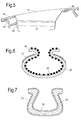
Figure 3 shows schematically a perspective view of a retention sleeve of the embodiment; -
Figure 4 shows schematically an end on view of the annulus filler and the retention sleeve of the embodiment when fitted to a groove of a rotor disc; -
Figure 5 shows schematically a side view of the fitted annulus filler and retention sleeve; -
Figure 6 shows schematically a transverse cross-section through the retention sleeve of -
Figures 3 to 5 ; and -
Figure 7 shows schematically a transverse cross-section through another embodiment of a retention sleeve. -
Figures 2 and3 show schematically perspective views of respectively anannulus filler 30 and aretention sleeve 35 of an annulus filler system according to an embodiment of the present invention. The filler has alid 31 which, in use, extends between two adjacent composite fan blades, and asupport body 32 extending beneath the lid and terminating in anelongate foot 33. The support body is formed by twoside walls 34 which join to the lid along respective edges of the lid and meet at the foot to give the body a V-shaped cross-section. The foot has a dovetail cross-section, e.g. with about 55° flank angles. Theretention sleeve 35 is shaped to wrap around thefoot 33. -
Figure 4 shows schematically an end on view of theannulus filler 30 and theretention sleeve 35 when fitted to agroove 36 of a metal rotor disc, andFigure 5 shows schematically a side view on the engine axial line of the fitted filler and sleeve. The groove is dovetail-shaped in cross-section, like thefoot 33, and is located on the disc rim in the outside face ofpost 38 formed betweenslots 39 which hold thefan blades 40 to the disc. An alternative arrangement has a circular foot cross-section and a correspondingly circular groove cross-section. The groove may follow a straight or a curved path from the front to the rear of the disc, and the sleeve is correspondingly straight or curved. To install the annulus filler system into the groove, the annulus filler is positioned outwardly of the groove and then moved radially inwardly. The widest part of the foot is proportioned to pass through theneck 41 of the groove so that the foot can be located completely in the groove. This enables fitting annulus fillers between blades that are shaped such that the fillers cannot be slid into position along the groove in a generally rearward direction of the engine. To prevent withdrawal of the annulus filler in a radially outward direction, theretention sleeve 35 is slidingly located into the gap formed between the groove and the foot. The sleeve wraps around the foot and protrudes past the neck of the groove to flare outwardly away from the support body so that thefree edges 42 of the sleeve are kept away from thesupport body 32. This helps to prevent the free edges from damaging the support body or posts 38 if there is relative movement between the sleeve and the body. - A
stop 43 at the end of thesleeve 35 prevents the sleeve from sliding in one direction out of thegroove 36. Sliding of the sleeve in the other direction can be prevented by asupport ring 44 fitted to the face of thedisc 37 after location of the sleeve. Thus together the stop and support ring can ensure repeatable axial positioning and retention of the sleeve. - When fitted, the
lid 31 of theannulus filler 30 forms a continuous airflow surface along with anose cone 45 at the front of the lid and aseal ring 46 at the rear of the lid. Sealing strips 47 extending along the edges of the lid seal the lid to the sides of theadjacent blades 40. - Advantageously, the
foot 33 andgroove 36 retention system can distribute loads over the entire axial length of thefiller 30. This allows the use of a lightweight filler which can improve engine efficiency. The weight of the filler can be reduced, for example, by forming thelid 31, theside walls 34 and thefoot 33 from carbon fibre reinforced plastic. The lid may be secured to the side walls by stitching through laminate layers, which can help to stiffen the edges of the lid, thereby providing a secure base for the sealing strips 47. The cavity formed by the lid and side walls can be filled with afoam core 48 or have an internal lattice structure, which can provide a lightweight resilient support to the lid and side walls. Such support can absorb impact energy and help the lid and side walls to retain their shape after impact deformation. The filler may be produced by foaming the material of the core within a pre-preg envelope of the lid, side walls and foot, and then completing the lid, side walls and foot by resin transfer moulding. - More specifically, the basic filler structure can be formed as a pre-preg tube by 3D Braiding or 3D weaving carbon fibres. An outer layer of glass fibre, e.g. woven or braided glass fibre can be applied to the foot to improve the galvanic isolation of the foot. A former can be placed inside the preform, which is then resin transfer moulded. The foam core is foamed in situ in the cavity and the surfaces sealed. The lid may have a coating, such as an elastomer (e.g. polyurethane), applied to resist sand, debris, and tool drops. Typically the coating would be applied as a sheet or sprayed on. A more sophisticated 3D braided or woven structure can be made to provide internal struts or lattice within the cavity, in which case more than one former may be required during moulding.
-
Figure 6 shows schematically a transverse cross-section through thesleeve 35. The inner surface of the sleeve is covered with a layer ofballotinis 48. The ballontinis are partially or fully embedded in a layer of resin or adhesive 49 such that the ballotinis ensure a minimum thickness for the galvanic isolation layer formed by the ballotinis and the resin. The galvanic isolation layer isolates the carbon fibres in the foot from the rest of the sleeve and themetal disc 37. If the ballotinis are partially embedded in the resin, only the proud portions of the ballotinis may make contact, in use, with thefoot 33. This can reduce the contact area of the foot with the sleeve. However, a paste adhesive may be used to fill the gaps between the ballotinis and provide a loose bond to the filler foot. Such a paste adhesive is preferably chosen to provide damping to the filler foot. - Two sizes of ballotinis may be used: the larger size being only partially embedded and having proud portions penetrating to an extent into the surface of the foot and thereby improving the locking between the foot and the sleeve, and the smaller size being fully embedded with the resin or paste adhesive to ensure a minimum thickness for the galvanic isolation layer.
- The sleeve has a
main body 50 which carries the layer ofballotinis 48 on its inner surface. The main body can be formed, for example, of a conventional titanium alloy, or a high damping alloy such as a titanium-niobium-oxygen alloy or a titanium-hafnium-oxygen alloy. Advantageously, a damping alloy can help to resist shear motion at the sleeve-disc interface and hence to reduce fretting. - The outer surface of the
main body 50 may be treated with ananti-frettage coating 51, such as molybdenum disulphide, tungsten disulphide or polytetrafluoroethylene. The coating may be applied only where needed rather than over the entire outer surface. The coating may be a sprayed on or applied by PVD/ebPVD. -
Figure 7 shows schematically a transverse cross-section through another embodiment of thesleeve 35. The sleeve is formed with various layers. Themain body 52 is preferably metallic and may, for example, be an alloy of titanium, or a high damping titanium alloy such as Ti3(Ta, Nb, V)+(Zr, Hf, O) (known as gum metal). The outer surface of the main body carries ananti-fretting coating 53. The inner surface of the main body carries agalvanic isolation layer 54 formed, for example, by a layer of glass fibre in a non-conductive matrix. - While the invention has been described in conjunction with the exemplary embodiments described above, many equivalent modifications and variations will be apparent to those skilled in the art when given this disclosure. For example, the filler may be slid into position along the groove in a generally rearward direction of the engine, i.e. the sleeve may not need to prevent withdrawal of the annulus filler in a radially outward direction. Accordingly, the exemplary embodiments of the invention set forth above are considered to be illustrative and not limiting.
- All references referred to above are hereby incorporated by reference.
Claims (11)
- An annulus filler system bridging the gap between two adjacent blades (40) attached to a rim of the rotor disc of a gas turbine engine, the system including:an annulus filler (30) having a lid (31) which extends between the adjacent blades and defines an airflow surface for air being drawn through the engine, and a support body (32) extending beneath the lid and terminating in an elongate foot (33) which, in use, extends along a groove (36) provided in the rim of the disc, the groove having a neck (41) which prevents withdrawal of the foot through the neck in a radially outward direction of the disc, anda sleeve (35) which, after installation of the filler, is slidably locatable into a gap between the foot and sides of the groove;wherein the foot is formed of composite material and characterised in that the sleeve provides a galvanic isolation layer (54) preventing galvanic corrosion between the foot and the disc.
- An annulus filler system according to claim 1, wherein the composite material comprises carbon fibres.
- An annulus filler system according to claim 1 or claim 2, wherein the galvanic isolation layer is selected from the group comprising: a layer of glass fibre in a non-conductive matrix; a glass layer formed or fused onto the surface of the sleeve; or a paint layer or coating.
- An annulus filler system according to claim 1, wherein the sleeve has a layer of ballotinis (48) within the galvanic isolation layer.
- An annulus filler according to claim 3, wherein the sleeve has a layer of ballotinis (48) within the galvanic isolation layer.
- An annulus filler system according to claim 4 or claim 5, wherein the layer of ballotinis are at the inner surface of the sleeve and contact, in use, the foot.
- An annulus filler system according to claim 4 or 5, wherein the ballotinis are embedded in an adhesive or resin (49).
- An annulus filler system according to any one of the previous claims, wherein the sleeve has an anti-frettage coating (51, 53) at its outer surface, the anti-frettage coating contacting, in use, the disc.
- An annulus filler system according to any one of the previous claims, wherein the sleeve has a metallic main body (50, 52) with the galvanic isolation layer on the inner surface of the sleeve.
- An annulus filler system according to any one of the previous claims, wherein the lid is formed from fibre-reinforced plastic.
- A rotor assembly for a gas turbine engine including:a rotor disc,a plurality of blades attached to a rim of the disc of a gas turbine engine, andannulus filler systems according to any one of claims 1 to 8 bridging the gaps between adjacent blades;wherein respective grooves are provided in the rim, the feet of the annulus fillers extending along the grooves, and the sleeves being located in the gaps between the feet and the sides of the grooves.
Applications Claiming Priority (1)
| Application Number | Priority Date | Filing Date | Title |
|---|---|---|---|
| GBGB1106276.7A GB201106276D0 (en) | 2011-04-14 | 2011-04-14 | Annulus filler system |
Publications (3)
| Publication Number | Publication Date |
|---|---|
| EP2511479A2 true EP2511479A2 (en) | 2012-10-17 |
| EP2511479A3 EP2511479A3 (en) | 2017-04-19 |
| EP2511479B1 EP2511479B1 (en) | 2018-01-24 |
Family
ID=44123053
Family Applications (1)
| Application Number | Title | Priority Date | Filing Date |
|---|---|---|---|
| EP12160837.6A Active EP2511479B1 (en) | 2011-04-14 | 2012-03-22 | Annulus filler system |
Country Status (3)
| Country | Link |
|---|---|
| US (1) | US20120263596A1 (en) |
| EP (1) | EP2511479B1 (en) |
| GB (1) | GB201106276D0 (en) |
Cited By (3)
| Publication number | Priority date | Publication date | Assignee | Title |
|---|---|---|---|---|
| EP2837773A1 (en) * | 2013-08-14 | 2015-02-18 | Rolls-Royce plc | Annulus filler and corresponding stage and gas turbine engine |
| EP4223980A3 (en) * | 2018-10-18 | 2024-01-17 | RTX Corporation | Rotor assembly with structural platforms for gas turbine engines |
| FR3159627A1 (en) * | 2024-02-27 | 2025-08-29 | Safran Aircraft Engines | INTER-BLADE PLATFORM FOR AN AIRCRAFT TURBOMACHINE PROPELLER |
Families Citing this family (15)
| Publication number | Priority date | Publication date | Assignee | Title |
|---|---|---|---|---|
| WO2015034612A1 (en) * | 2013-09-09 | 2015-03-12 | United Technologies Corporation | Fan blades and manufacture methods |
| WO2015069335A2 (en) * | 2013-09-09 | 2015-05-14 | United Technologies Corporation | Fan blades and manufacture methods |
| EP3080417B1 (en) * | 2013-12-13 | 2023-03-15 | Raytheon Technologies Corporation | Fan blade platform spacer mounting |
| US10156151B2 (en) | 2014-10-23 | 2018-12-18 | Rolls-Royce North American Technologies Inc. | Composite annulus filler |
| US20170101878A1 (en) * | 2015-10-08 | 2017-04-13 | General Electric Company | Low modulus insert for a component of a gas turbine engine |
| US10605117B2 (en) * | 2015-10-08 | 2020-03-31 | General Electric Company | Fan platform for a gas turbine engine |
| US10557350B2 (en) * | 2017-03-30 | 2020-02-11 | General Electric Company | I beam blade platform |
| US10746031B2 (en) | 2017-07-18 | 2020-08-18 | Rolls-Royce Corporation | Annulus filler |
| US11078839B2 (en) | 2018-01-22 | 2021-08-03 | Rolls-Royce Corporation | Composite nosecone |
| US11209084B2 (en) * | 2019-05-30 | 2021-12-28 | The Boeing Company | Seal, aircraft including the seal, and methods therefor |
| US11421538B2 (en) | 2020-05-12 | 2022-08-23 | Rolls-Royce Corporation | Composite aerofoils |
| US11506083B2 (en) | 2020-06-03 | 2022-11-22 | Rolls-Royce Corporalion | Composite liners for turbofan engines |
| CN113833691A (en) * | 2020-06-08 | 2021-12-24 | 中国航发商用航空发动机有限责任公司 | Fan assembly and turbofan engine |
| US12012857B2 (en) | 2022-10-14 | 2024-06-18 | Rtx Corporation | Platform for an airfoil of a gas turbine engine |
| US12049833B1 (en) * | 2023-05-26 | 2024-07-30 | General Electric Company | Rotor disks with disk post inserts and methods of assembling the same |
Citations (2)
| Publication number | Priority date | Publication date | Assignee | Title |
|---|---|---|---|---|
| US4655687A (en) | 1985-02-20 | 1987-04-07 | Rolls-Royce | Rotors for gas turbine engines |
| US6132175A (en) | 1997-05-29 | 2000-10-17 | Alliedsignal, Inc. | Compliant sleeve for ceramic turbine blades |
Family Cites Families (28)
| Publication number | Priority date | Publication date | Assignee | Title |
|---|---|---|---|---|
| US3114045A (en) * | 1956-08-20 | 1963-12-10 | Thorn Electrical Ind Ltd | Photo-conductive translucent electroluminescent device and method of manufacture |
| DE1251338B (en) * | 1962-12-14 | 1967-10-05 | Aktiengesellschaft Brown, Boveri &. Cie , Baden (Schweiz) | Method for attaching blades in turbine rotors |
| US3647316A (en) * | 1970-04-28 | 1972-03-07 | Curtiss Wright Corp | Variable permeability and oxidation-resistant airfoil |
| DE2108176A1 (en) * | 1971-02-20 | 1972-08-31 | Motoren Turbinen Union | Fastening of ceramic turbine blades |
| US4169694A (en) * | 1977-07-20 | 1979-10-02 | Electric Power Research Institute, Inc. | Ceramic rotor blade having root with double curvature |
| US4207029A (en) * | 1978-06-12 | 1980-06-10 | Avco Corporation | Turbine rotor assembly of ceramic blades to metallic disc |
| US4820126A (en) * | 1988-02-22 | 1989-04-11 | Westinghouse Electric Corp. | Turbomachine rotor assembly having reduced stress concentrations |
| US5118257A (en) * | 1990-05-25 | 1992-06-02 | Sundstrand Corporation | Boot attachment for composite turbine blade, turbine blade and method of making turbine blade |
| US5314309A (en) * | 1990-05-25 | 1994-05-24 | Anthony Blakeley | Turbine blade with metallic attachment and method of making the same |
| FI88935C (en) * | 1990-09-04 | 1993-07-26 | Tampella Telatek Oy | Process for coating a steam turbine and associated steel surfaces |
| US5160243A (en) * | 1991-01-15 | 1992-11-03 | General Electric Company | Turbine blade wear protection system with multilayer shim |
| US5240375A (en) * | 1992-01-10 | 1993-08-31 | General Electric Company | Wear protection system for turbine engine rotor and blade |
| AU734375B2 (en) * | 1997-08-21 | 2001-06-14 | Toray Industries, Inc. | Light metal/CFRP-made structural members |
| DE19859477B4 (en) * | 1998-12-22 | 2005-06-23 | Mtu Aero Engines Gmbh | Wear protection layer |
| US6290466B1 (en) * | 1999-09-17 | 2001-09-18 | General Electric Company | Composite blade root attachment |
| US6431835B1 (en) * | 2000-10-17 | 2002-08-13 | Honeywell International, Inc. | Fan blade compliant shim |
| US7094033B2 (en) * | 2004-01-21 | 2006-08-22 | General Electric Company | Methods and apparatus for assembling gas turbine engines |
| US7329101B2 (en) * | 2004-12-29 | 2008-02-12 | General Electric Company | Ceramic composite with integrated compliance/wear layer |
| FR2890126B1 (en) * | 2005-08-26 | 2010-10-29 | Snecma | ASSEMBLY AND METHOD FOR THE FOOT ASSEMBLY OF A TURBOMACHINE, BLOWER, COMPRESSOR AND TURBOMACHINE BLADE COMPRISING SUCH AN ASSEMBLY |
| US7435056B2 (en) * | 2006-02-28 | 2008-10-14 | Honeywell International Inc. | Leading edge erosion protection for composite stator vanes |
| US7429165B2 (en) * | 2006-06-14 | 2008-09-30 | General Electric Company | Hybrid blade for a steam turbine |
| FR2918702B1 (en) * | 2007-07-13 | 2009-10-16 | Snecma Sa | CLINKING FOR TURBOMACHINE BLADE |
| FR2918703B1 (en) * | 2007-07-13 | 2009-10-16 | Snecma Sa | ROTOR ASSEMBLY OF TURBOMACHINE |
| US20090176110A1 (en) * | 2008-01-08 | 2009-07-09 | General Electric Company | Erosion and corrosion-resistant coating system and process therefor |
| GB0814718D0 (en) * | 2008-08-13 | 2008-09-17 | Rolls Royce Plc | Annulus filler |
| US20100226783A1 (en) * | 2009-03-06 | 2010-09-09 | General Electric Company | Erosion and Corrosion Resistant Turbine Compressor Airfoil and Method of Making the Same |
| US8282356B2 (en) * | 2009-11-03 | 2012-10-09 | General Electric Company | Apparatus and method for reducing wear in disk lugs |
| US8834126B2 (en) * | 2011-06-30 | 2014-09-16 | United Technologies Corporation | Fan blade protection system |
-
2011
- 2011-04-14 GB GBGB1106276.7A patent/GB201106276D0/en not_active Ceased
-
2012
- 2012-03-22 US US13/427,427 patent/US20120263596A1/en not_active Abandoned
- 2012-03-22 EP EP12160837.6A patent/EP2511479B1/en active Active
Patent Citations (2)
| Publication number | Priority date | Publication date | Assignee | Title |
|---|---|---|---|---|
| US4655687A (en) | 1985-02-20 | 1987-04-07 | Rolls-Royce | Rotors for gas turbine engines |
| US6132175A (en) | 1997-05-29 | 2000-10-17 | Alliedsignal, Inc. | Compliant sleeve for ceramic turbine blades |
Cited By (3)
| Publication number | Priority date | Publication date | Assignee | Title |
|---|---|---|---|---|
| EP2837773A1 (en) * | 2013-08-14 | 2015-02-18 | Rolls-Royce plc | Annulus filler and corresponding stage and gas turbine engine |
| EP4223980A3 (en) * | 2018-10-18 | 2024-01-17 | RTX Corporation | Rotor assembly with structural platforms for gas turbine engines |
| FR3159627A1 (en) * | 2024-02-27 | 2025-08-29 | Safran Aircraft Engines | INTER-BLADE PLATFORM FOR AN AIRCRAFT TURBOMACHINE PROPELLER |
Also Published As
| Publication number | Publication date |
|---|---|
| US20120263596A1 (en) | 2012-10-18 |
| EP2511479B1 (en) | 2018-01-24 |
| GB201106276D0 (en) | 2011-05-25 |
| EP2511479A3 (en) | 2017-04-19 |
Similar Documents
| Publication | Publication Date | Title |
|---|---|---|
| EP2511479B1 (en) | Annulus filler system | |
| US9145784B2 (en) | Annulus filler system | |
| US9689269B2 (en) | Leading edge protector | |
| US8029231B2 (en) | Fan track liner assembly | |
| EP3044415B1 (en) | Airfoil with an integrally stiffened composite cover | |
| US8535013B2 (en) | Aeroengine fan assembly | |
| EP3447306B1 (en) | Fan containment case for gas turbine engine | |
| US20140086751A1 (en) | Annulus filler for axial flow machine | |
| EP2706241B1 (en) | Rotor blade stage | |
| EP2837772B1 (en) | Annulus filler and corresponding stage and gas turbine engine | |
| EP2353830A2 (en) | Method of manufacturing a composite fan blade with co-cured sheath, and corresponding fan blade | |
| EP2253803B1 (en) | Composite aerofoil blade with wear-resistant tip and corresponding method | |
| US9957835B2 (en) | Fan track liner assembly | |
| EP2447476A2 (en) | Annulus filler for a rotor disk of a gas turbine | |
| US11905839B2 (en) | Attachment of an acoustic shroud to a housing shell for an aircraft turbine engine | |
| US10247014B2 (en) | Composite compressor blade and method of assembling | |
| EP3012092B1 (en) | Composite annulus filler and method for its manufacture | |
| EP2837773A1 (en) | Annulus filler and corresponding stage and gas turbine engine | |
| GB2498194A (en) | Ice impact panel for a gas turbine engine | |
| GB2484988A (en) | Annulus filler for gas turbine engine rotor disc |
Legal Events
| Date | Code | Title | Description |
|---|---|---|---|
| PUAI | Public reference made under article 153(3) epc to a published international application that has entered the european phase |
Free format text: ORIGINAL CODE: 0009012 |
|
| AK | Designated contracting states |
Kind code of ref document: A2 Designated state(s): AL AT BE BG CH CY CZ DE DK EE ES FI FR GB GR HR HU IE IS IT LI LT LU LV MC MK MT NL NO PL PT RO RS SE SI SK SM TR |
|
| AX | Request for extension of the european patent |
Extension state: BA ME |
|
| RAP1 | Party data changed (applicant data changed or rights of an application transferred) |
Owner name: ROLLS-ROYCE PLC |
|
| PUAL | Search report despatched |
Free format text: ORIGINAL CODE: 0009013 |
|
| AK | Designated contracting states |
Kind code of ref document: A3 Designated state(s): AL AT BE BG CH CY CZ DE DK EE ES FI FR GB GR HR HU IE IS IT LI LT LU LV MC MK MT NL NO PL PT RO RS SE SI SK SM TR |
|
| AX | Request for extension of the european patent |
Extension state: BA ME |
|
| RIC1 | Information provided on ipc code assigned before grant |
Ipc: F01D 5/28 20060101AFI20170311BHEP Ipc: F01D 11/00 20060101ALI20170311BHEP Ipc: F01D 5/30 20060101ALI20170311BHEP |
|
| STAA | Information on the status of an ep patent application or granted ep patent |
Free format text: STATUS: REQUEST FOR EXAMINATION WAS MADE |
|
| 17P | Request for examination filed |
Effective date: 20170816 |
|
| RBV | Designated contracting states (corrected) |
Designated state(s): AL AT BE BG CH CY CZ DE DK EE ES FI FR GB GR HR HU IE IS IT LI LT LU LV MC MK MT NL NO PL PT RO RS SE SI SK SM TR |
|
| RIC1 | Information provided on ipc code assigned before grant |
Ipc: F01D 5/28 20060101AFI20170907BHEP Ipc: F01D 11/00 20060101ALI20170907BHEP Ipc: F01D 5/30 20060101ALI20170907BHEP |
|
| GRAP | Despatch of communication of intention to grant a patent |
Free format text: ORIGINAL CODE: EPIDOSNIGR1 |
|
| STAA | Information on the status of an ep patent application or granted ep patent |
Free format text: STATUS: GRANT OF PATENT IS INTENDED |
|
| GRAS | Grant fee paid |
Free format text: ORIGINAL CODE: EPIDOSNIGR3 |
|
| INTG | Intention to grant announced |
Effective date: 20171102 |
|
| GRAA | (expected) grant |
Free format text: ORIGINAL CODE: 0009210 |
|
| STAA | Information on the status of an ep patent application or granted ep patent |
Free format text: STATUS: THE PATENT HAS BEEN GRANTED |
|
| AK | Designated contracting states |
Kind code of ref document: B1 Designated state(s): AL AT BE BG CH CY CZ DE DK EE ES FI FR GB GR HR HU IE IS IT LI LT LU LV MC MK MT NL NO PL PT RO RS SE SI SK SM TR |
|
| REG | Reference to a national code |
Ref country code: GB Ref legal event code: FG4D |
|
| REG | Reference to a national code |
Ref country code: CH Ref legal event code: EP |
|
| REG | Reference to a national code |
Ref country code: AT Ref legal event code: REF Ref document number: 965909 Country of ref document: AT Kind code of ref document: T Effective date: 20180215 |
|
| REG | Reference to a national code |
Ref country code: IE Ref legal event code: FG4D |
|
| REG | Reference to a national code |
Ref country code: DE Ref legal event code: R096 Ref document number: 602012042257 Country of ref document: DE |
|
| REG | Reference to a national code |
Ref country code: FR Ref legal event code: PLFP Year of fee payment: 7 |
|
| REG | Reference to a national code |
Ref country code: NL Ref legal event code: MP Effective date: 20180124 |
|
| REG | Reference to a national code |
Ref country code: LT Ref legal event code: MG4D |
|
| REG | Reference to a national code |
Ref country code: AT Ref legal event code: MK05 Ref document number: 965909 Country of ref document: AT Kind code of ref document: T Effective date: 20180124 |
|
| PG25 | Lapsed in a contracting state [announced via postgrant information from national office to epo] |
Ref country code: NL Free format text: LAPSE BECAUSE OF FAILURE TO SUBMIT A TRANSLATION OF THE DESCRIPTION OR TO PAY THE FEE WITHIN THE PRESCRIBED TIME-LIMIT Effective date: 20180124 |
|
| PG25 | Lapsed in a contracting state [announced via postgrant information from national office to epo] |
Ref country code: ES Free format text: LAPSE BECAUSE OF FAILURE TO SUBMIT A TRANSLATION OF THE DESCRIPTION OR TO PAY THE FEE WITHIN THE PRESCRIBED TIME-LIMIT Effective date: 20180124 Ref country code: FI Free format text: LAPSE BECAUSE OF FAILURE TO SUBMIT A TRANSLATION OF THE DESCRIPTION OR TO PAY THE FEE WITHIN THE PRESCRIBED TIME-LIMIT Effective date: 20180124 Ref country code: NO Free format text: LAPSE BECAUSE OF FAILURE TO SUBMIT A TRANSLATION OF THE DESCRIPTION OR TO PAY THE FEE WITHIN THE PRESCRIBED TIME-LIMIT Effective date: 20180424 Ref country code: HR Free format text: LAPSE BECAUSE OF FAILURE TO SUBMIT A TRANSLATION OF THE DESCRIPTION OR TO PAY THE FEE WITHIN THE PRESCRIBED TIME-LIMIT Effective date: 20180124 Ref country code: LT Free format text: LAPSE BECAUSE OF FAILURE TO SUBMIT A TRANSLATION OF THE DESCRIPTION OR TO PAY THE FEE WITHIN THE PRESCRIBED TIME-LIMIT Effective date: 20180124 Ref country code: CY Free format text: LAPSE BECAUSE OF FAILURE TO SUBMIT A TRANSLATION OF THE DESCRIPTION OR TO PAY THE FEE WITHIN THE PRESCRIBED TIME-LIMIT Effective date: 20180124 |
|
| PG25 | Lapsed in a contracting state [announced via postgrant information from national office to epo] |
Ref country code: IS Free format text: LAPSE BECAUSE OF FAILURE TO SUBMIT A TRANSLATION OF THE DESCRIPTION OR TO PAY THE FEE WITHIN THE PRESCRIBED TIME-LIMIT Effective date: 20180524 Ref country code: BG Free format text: LAPSE BECAUSE OF FAILURE TO SUBMIT A TRANSLATION OF THE DESCRIPTION OR TO PAY THE FEE WITHIN THE PRESCRIBED TIME-LIMIT Effective date: 20180424 Ref country code: GR Free format text: LAPSE BECAUSE OF FAILURE TO SUBMIT A TRANSLATION OF THE DESCRIPTION OR TO PAY THE FEE WITHIN THE PRESCRIBED TIME-LIMIT Effective date: 20180425 Ref country code: LV Free format text: LAPSE BECAUSE OF FAILURE TO SUBMIT A TRANSLATION OF THE DESCRIPTION OR TO PAY THE FEE WITHIN THE PRESCRIBED TIME-LIMIT Effective date: 20180124 Ref country code: AT Free format text: LAPSE BECAUSE OF FAILURE TO SUBMIT A TRANSLATION OF THE DESCRIPTION OR TO PAY THE FEE WITHIN THE PRESCRIBED TIME-LIMIT Effective date: 20180124 Ref country code: SE Free format text: LAPSE BECAUSE OF FAILURE TO SUBMIT A TRANSLATION OF THE DESCRIPTION OR TO PAY THE FEE WITHIN THE PRESCRIBED TIME-LIMIT Effective date: 20180124 Ref country code: PL Free format text: LAPSE BECAUSE OF FAILURE TO SUBMIT A TRANSLATION OF THE DESCRIPTION OR TO PAY THE FEE WITHIN THE PRESCRIBED TIME-LIMIT Effective date: 20180124 Ref country code: RS Free format text: LAPSE BECAUSE OF FAILURE TO SUBMIT A TRANSLATION OF THE DESCRIPTION OR TO PAY THE FEE WITHIN THE PRESCRIBED TIME-LIMIT Effective date: 20180124 |
|
| REG | Reference to a national code |
Ref country code: DE Ref legal event code: R097 Ref document number: 602012042257 Country of ref document: DE |
|
| PG25 | Lapsed in a contracting state [announced via postgrant information from national office to epo] |
Ref country code: EE Free format text: LAPSE BECAUSE OF FAILURE TO SUBMIT A TRANSLATION OF THE DESCRIPTION OR TO PAY THE FEE WITHIN THE PRESCRIBED TIME-LIMIT Effective date: 20180124 Ref country code: IT Free format text: LAPSE BECAUSE OF FAILURE TO SUBMIT A TRANSLATION OF THE DESCRIPTION OR TO PAY THE FEE WITHIN THE PRESCRIBED TIME-LIMIT Effective date: 20180124 Ref country code: AL Free format text: LAPSE BECAUSE OF FAILURE TO SUBMIT A TRANSLATION OF THE DESCRIPTION OR TO PAY THE FEE WITHIN THE PRESCRIBED TIME-LIMIT Effective date: 20180124 Ref country code: RO Free format text: LAPSE BECAUSE OF FAILURE TO SUBMIT A TRANSLATION OF THE DESCRIPTION OR TO PAY THE FEE WITHIN THE PRESCRIBED TIME-LIMIT Effective date: 20180124 |
|
| REG | Reference to a national code |
Ref country code: CH Ref legal event code: PL |
|
| PG25 | Lapsed in a contracting state [announced via postgrant information from national office to epo] |
Ref country code: MC Free format text: LAPSE BECAUSE OF FAILURE TO SUBMIT A TRANSLATION OF THE DESCRIPTION OR TO PAY THE FEE WITHIN THE PRESCRIBED TIME-LIMIT Effective date: 20180124 Ref country code: CZ Free format text: LAPSE BECAUSE OF FAILURE TO SUBMIT A TRANSLATION OF THE DESCRIPTION OR TO PAY THE FEE WITHIN THE PRESCRIBED TIME-LIMIT Effective date: 20180124 Ref country code: SK Free format text: LAPSE BECAUSE OF FAILURE TO SUBMIT A TRANSLATION OF THE DESCRIPTION OR TO PAY THE FEE WITHIN THE PRESCRIBED TIME-LIMIT Effective date: 20180124 Ref country code: SM Free format text: LAPSE BECAUSE OF FAILURE TO SUBMIT A TRANSLATION OF THE DESCRIPTION OR TO PAY THE FEE WITHIN THE PRESCRIBED TIME-LIMIT Effective date: 20180124 Ref country code: DK Free format text: LAPSE BECAUSE OF FAILURE TO SUBMIT A TRANSLATION OF THE DESCRIPTION OR TO PAY THE FEE WITHIN THE PRESCRIBED TIME-LIMIT Effective date: 20180124 |
|
| PLBE | No opposition filed within time limit |
Free format text: ORIGINAL CODE: 0009261 |
|
| STAA | Information on the status of an ep patent application or granted ep patent |
Free format text: STATUS: NO OPPOSITION FILED WITHIN TIME LIMIT |
|
| REG | Reference to a national code |
Ref country code: BE Ref legal event code: MM Effective date: 20180331 |
|
| REG | Reference to a national code |
Ref country code: IE Ref legal event code: MM4A |
|
| PG25 | Lapsed in a contracting state [announced via postgrant information from national office to epo] |
Ref country code: LU Free format text: LAPSE BECAUSE OF NON-PAYMENT OF DUE FEES Effective date: 20180322 |
|
| 26N | No opposition filed |
Effective date: 20181025 |
|
| PG25 | Lapsed in a contracting state [announced via postgrant information from national office to epo] |
Ref country code: IE Free format text: LAPSE BECAUSE OF NON-PAYMENT OF DUE FEES Effective date: 20180322 |
|
| PG25 | Lapsed in a contracting state [announced via postgrant information from national office to epo] |
Ref country code: BE Free format text: LAPSE BECAUSE OF NON-PAYMENT OF DUE FEES Effective date: 20180331 Ref country code: LI Free format text: LAPSE BECAUSE OF NON-PAYMENT OF DUE FEES Effective date: 20180331 Ref country code: SI Free format text: LAPSE BECAUSE OF FAILURE TO SUBMIT A TRANSLATION OF THE DESCRIPTION OR TO PAY THE FEE WITHIN THE PRESCRIBED TIME-LIMIT Effective date: 20180124 Ref country code: CH Free format text: LAPSE BECAUSE OF NON-PAYMENT OF DUE FEES Effective date: 20180331 |
|
| PG25 | Lapsed in a contracting state [announced via postgrant information from national office to epo] |
Ref country code: MT Free format text: LAPSE BECAUSE OF NON-PAYMENT OF DUE FEES Effective date: 20180322 |
|
| PG25 | Lapsed in a contracting state [announced via postgrant information from national office to epo] |
Ref country code: TR Free format text: LAPSE BECAUSE OF FAILURE TO SUBMIT A TRANSLATION OF THE DESCRIPTION OR TO PAY THE FEE WITHIN THE PRESCRIBED TIME-LIMIT Effective date: 20180124 |
|
| PG25 | Lapsed in a contracting state [announced via postgrant information from national office to epo] |
Ref country code: PT Free format text: LAPSE BECAUSE OF FAILURE TO SUBMIT A TRANSLATION OF THE DESCRIPTION OR TO PAY THE FEE WITHIN THE PRESCRIBED TIME-LIMIT Effective date: 20180124 Ref country code: HU Free format text: LAPSE BECAUSE OF FAILURE TO SUBMIT A TRANSLATION OF THE DESCRIPTION OR TO PAY THE FEE WITHIN THE PRESCRIBED TIME-LIMIT; INVALID AB INITIO Effective date: 20120322 |
|
| PG25 | Lapsed in a contracting state [announced via postgrant information from national office to epo] |
Ref country code: MK Free format text: LAPSE BECAUSE OF NON-PAYMENT OF DUE FEES Effective date: 20180124 |
|
| P01 | Opt-out of the competence of the unified patent court (upc) registered |
Effective date: 20230528 |
|
| PGFP | Annual fee paid to national office [announced via postgrant information from national office to epo] |
Ref country code: GB Payment date: 20260323 Year of fee payment: 15 |
|
| PGFP | Annual fee paid to national office [announced via postgrant information from national office to epo] |
Ref country code: DE Payment date: 20260320 Year of fee payment: 15 |
|
| PGFP | Annual fee paid to national office [announced via postgrant information from national office to epo] |
Ref country code: FR Payment date: 20260323 Year of fee payment: 15 |