EP2511158A1 - Angle sensor - Google Patents
Angle sensor Download PDFInfo
- Publication number
- EP2511158A1 EP2511158A1 EP20120164118 EP12164118A EP2511158A1 EP 2511158 A1 EP2511158 A1 EP 2511158A1 EP 20120164118 EP20120164118 EP 20120164118 EP 12164118 A EP12164118 A EP 12164118A EP 2511158 A1 EP2511158 A1 EP 2511158A1
- Authority
- EP
- European Patent Office
- Prior art keywords
- coupling member
- main gear
- angle sensor
- gear
- rotating shaft
- Prior art date
- Legal status (The legal status is an assumption and is not a legal conclusion. Google has not performed a legal analysis and makes no representation as to the accuracy of the status listed.)
- Withdrawn
Links
Images

Classifications
-
- G—PHYSICS
- G01—MEASURING; TESTING
- G01B—MEASURING LENGTH, THICKNESS OR SIMILAR LINEAR DIMENSIONS; MEASURING ANGLES; MEASURING AREAS; MEASURING IRREGULARITIES OF SURFACES OR CONTOURS
- G01B7/00—Measuring arrangements characterised by the use of electric or magnetic techniques
- G01B7/30—Measuring arrangements characterised by the use of electric or magnetic techniques for measuring angles or tapers; for testing the alignment of axes
-
- B—PERFORMING OPERATIONS; TRANSPORTING
- B62—LAND VEHICLES FOR TRAVELLING OTHERWISE THAN ON RAILS
- B62D—MOTOR VEHICLES; TRAILERS
- B62D15/00—Steering not otherwise provided for
- B62D15/02—Steering position indicators ; Steering position determination; Steering aids
- B62D15/021—Determination of steering angle
- B62D15/0215—Determination of steering angle by measuring on the steering column
-
- B—PERFORMING OPERATIONS; TRANSPORTING
- B60—VEHICLES IN GENERAL
- B60R—VEHICLES, VEHICLE FITTINGS, OR VEHICLE PARTS, NOT OTHERWISE PROVIDED FOR
- B60R16/00—Electric or fluid circuits specially adapted for vehicles and not otherwise provided for; Arrangement of elements of electric or fluid circuits specially adapted for vehicles and not otherwise provided for
- B60R16/02—Electric or fluid circuits specially adapted for vehicles and not otherwise provided for; Arrangement of elements of electric or fluid circuits specially adapted for vehicles and not otherwise provided for electric constitutive elements
-
- G—PHYSICS
- G01—MEASURING; TESTING
- G01D—MEASURING NOT SPECIALLY ADAPTED FOR A SPECIFIC VARIABLE; ARRANGEMENTS FOR MEASURING TWO OR MORE VARIABLES NOT COVERED IN A SINGLE OTHER SUBCLASS; TARIFF METERING APPARATUS; MEASURING OR TESTING NOT OTHERWISE PROVIDED FOR
- G01D5/00—Mechanical means for transferring the output of a sensing member; Means for converting the output of a sensing member to another variable where the form or nature of the sensing member does not constrain the means for converting; Transducers not specially adapted for a specific variable
- G01D5/12—Mechanical means for transferring the output of a sensing member; Means for converting the output of a sensing member to another variable where the form or nature of the sensing member does not constrain the means for converting; Transducers not specially adapted for a specific variable using electric or magnetic means
Definitions
- the present invention relates generally to angle sensors and, more particularly, to an angle sensor, configured to compensate eccentricity of a main gear rotated by a rotating shaft, thus preventing abrasion of a gear and reduction in tooth strength and thereby improving operational reliability and durability.
- an auxiliary steering system supported by additional power is used as a device for ensuring steering stability of a vehicle.
- the auxiliary steering system uses a hydraulic pressure.
- an electronic power steering system which consumes less power and is excellent in accuracy, has been recently used.
- Such an electronic power steering system drives a motor by an electronic control unit depending on driving conditions detected by a vehicle speed sensor, an angle sensor and a torque sensor, thus ensuring turning stability and providing a rapid restoring force, and thereby allowing a driver to safely drive a vehicle.
- EPS electronic power steering system
- the angle sensor is a device that outputs an electric signal in proportion to a rotation angle of a steering shaft. Recently, the angle sensor is frequently combined with the torque sensor measuring steering torque to form an assembly.
- FIG. 1 is a plan view illustrating an example of the angle sensor.
- a main gear 20 attached to a steering shaft rotates in conjunction with the steering wheel, and there occurs a difference in rotation angle between input and output shafts of the steering shaft.
- a magnetic device detects magnetic fields and rotating directions of magnets 31 and 32 attached to subsidiary gears 21 and 22 engaging with the main gear 20, and thereafter sends a detected signal to an electronic control unit.
- the main gear 20 and the subsidiary gears 21 and 22 are coupled to an interior of a housing 10.
- the main gear 20 is integrally formed with a coupling member by injection molding, or is coupled to the coupling member by bonding.
- the coupling member is provided on a portion of the housing 10 through which a rotating shaft passes.
- an object of the present invention is to provide an angle sensor, which improves a main-gear coupling structure of the angle sensor, thus enabling rotation to be precisely transmitted even if vibration and eccentricity occur, and guaranteeing durability.
- an angle sensor comprising: a housing formed with a space for allowing a rotating shaft to pass, a coupling member disposed in the housing and coupled with the rotating shaft to rotate along with the rotating shaft, a ring-shaped main gear coupled to an outer circumference of the coupling member and rotated along with the coupling member, a subsidiary gear meshed with the main gear, an inner protrusion protruding inwards from an inner circumference of the main gear, and a groove formed in the coupling member, the inner protrusion being inserted into the groove to transmit a rotating force from the coupling member to the main gear.
- the angle sensor is advantageous in that it can precisely transmit the rotating force from the coupling member to the main gear by the inner protrusion, and can more efficiently compensate for undesirable movement of the coupling member in comparison with a coupling structure using press-fitting or injection molding.
- the inner circumference of the main gear is spaced apart from the outer circumference of the coupling member to allow a central axis of the main gear to be eccentric from a central axis of the coupling member.
- a fine gap between the main gear and the coupling member can compensates for the eccentricity of the main gear, thus improving the durability of the gear.
- the angle sensor is advantageous in that it can smoothly compensate for the eccentricity.
- the groove is formed in an axial direction of the coupling member, and the main gear is coupled to the coupling member by sliding in a direction from an upper position to a lower position thereof.
- the angle sensor is advantageous in that it facilitates a coupling process and minimizes damage and defective coupling during assembly.
- two or more inner protrusions are disposed on the inner circumference of the main gear each at regular interval to a circumferential direction. Thus, it is possible to precisely transmit a rotating force.
- the angle sensor according to the present invention is configured so that the coupling member is interposed between the main gear and the rotating shaft to compensate for the eccentricity of the main gear rotated by the rotating shaft, the rotating force is transmitted from the coupling member to the main gear by means of the inner protrusion and the groove, and the coupling member and the main gear are spaced apart from each other to allow the central axis of the coupling member to be eccentric from that of the main gear.
- Such a configuration prevents the gear from being worn out and prevents tooth strength from being reduced, thus improving operational reliability and durability.
- the angle sensor can minimize a fatigue degree of a member and prevent a defective assembly in comparison with a coupling structure using press-fitting or injection molding, thus increasing productivity.
- FIG. 2 is a plan view showing a main-gear coupling portion of an angle sensor in accordance with an exemplary embodiment of the present invention
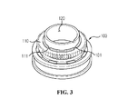
- FIG. 3 is a perspective view showing the main-gear coupling portion of the angle sensor in accordance with the exemplary embodiment of the present invention.
- the angle sensor is provided with main and subsidiary gears in housing. Further, the angle sensor includes magnetic members connected to the gears, a Hall IC detecting magnetic variation, and a printed circuit board (PCB).
- PCB printed circuit board
- the housing may be mounted on a rotating shaft of a steering wheel, and is fixedly disposed regardless of rotation of the rotating shaft without hindering the rotating shaft from rotating.
- the main gear 110 has a plurality of teeth on a ring-shaped outer circumference thereof, and is connected at a central portion thereof to the rotating shaft to be rotated along with the steering wheel when it rotates.
- angle sensor of the steering wheel
- angle sensor may be used to measure angles of various rotating shafts or rotary members.
- a first subsidiary gear 21 (see FIG. 1 ) engaging with the main gear 110 is rotated by rotation of the main gear 110, that is, rotation of the rotating shaft.
- a rotation ratio of the main gear 110 to the first subsidiary gear 21 is in reverse proportion to a ratio of teeth between the main gear 110 and the first subsidiary gear 21.
- a second subsidiary gear 22 engages with the first subsidiary gear 21 to be rotated by the rotation of the first subsidiary gear 21.
- the subsidiary gears 21 and 22 are provided with magnets 31 and 32 to change magnetic fields by rotation.
- a change in magnetic field is detected by the Hall IC accommodated in the housing 10 and used as a parameter for detecting a rotating angle or a rotating angular velocity.
- the first subsidiary gear and the second subsidiary gear may be omitted, the second subsidiary gear may engage with the main gear, and three or more subsidiary gears may be provided if necessary.
- a coupling member 100 is interposed between the main gear 110 and the rotating shaft.
- both the coupling member 100 and the main gear 110 are mechanically rotated together, but the coupling member 100 and the main gear 110 are coupled to each other to have a gap therebetween.
- the coupling member 100 approximately takes a shape of a cylinder. A lower portion of the coupling member 100 is coupled to the housing 10, while the main gear 110 is coupled to an outer circumference of an upper portion of the coupling member 100.
- a central portion of the coupling member 100 is hollow, and has a shaft insertion hole 120 to be coupled to the rotating shaft. Since the coupling member 10 rotates along with the rotating shaft, it is preferable that a central axis of the rotating shaft be aligned with a central axis of the coupling member 100.
- gear teeth may be worn out or reduced in strength.
- the main gear 110 can precisely maintain engagement with the subsidiary gear. This results in improvement on operational reliability and durability.
- inner protrusions 111 are provided on the inner circumference of the main gear 110 in such a way as to protrude inwards therefrom.
- Grooves 101 are formed at predetermined positions of the coupling member 100 to correspond to the inner protrusions 111 of the main gear 110.
- the inner protrusions 111 are caught by the grooves 101, thus transmitting a rotating force from the coupling member 100 to the main gear 110.
- the main gear 110 may be coupled to the coupling member 100 by sliding in a direction from an upper position to a lower position of the coupling member 100.
- each groove 101 is formed to be parallel to an axial direction of the coupling member 100, and each inner protrusion 111 of the main gear 110 is inserted into the groove 101 in a direction from an upper position to a lower position thereof.
- FIG. 2 shows an example wherein four inner protrusions 111 are formed on the inner circumference of the main gear 110 at regular intervals. However, a single inner protrusion 111 may be formed, or two or more inner protrusions 111 may be selectively formed along the inner circumference of the main gear 110.
- a fine gap exists between a side wall of the inner protrusion 111 and an inner wall of the groove 101. Such a gap is advantageous in that it allows the central axis of the main gear 110 to be eccentric from the central axis of the coupling member 100.
- the angle sensor according to the present invention is configured so that the coupling member 100 is interposed between the main gear 110 and the rotating shaft to compensate for the eccentricity of the main gear 110 rotated by the rotating shaft, the rotating force is transmitted from the coupling member 100 to the main gear 110 by means of the inner protrusion 111 and the groove 101, and the coupling member 100 and the main gear 110 are spaced apart from each other to allow the central axis of the coupling member 100 to be eccentric from that of the main gear 110.
- Such a configuration prevents the gear from being worn out and prevents tooth strength from being reduced, thus improving operational reliability and durability.
- the angle sensor of the present invention embraces a device for measuring the rotation of the rotating shaft of the steering wheel, the rotating angle or angular velocity of a rotary member or device.
- the structure of coupling the main gear with the coupling member may be naturally applied to the subsidiary gear.
Landscapes
- Engineering & Computer Science (AREA)
- Mechanical Engineering (AREA)
- Chemical & Material Sciences (AREA)
- Combustion & Propulsion (AREA)
- Transportation (AREA)
- Physics & Mathematics (AREA)
- General Physics & Mathematics (AREA)
- Power Steering Mechanism (AREA)
- Transmission And Conversion Of Sensor Element Output (AREA)
- Measurement Of Length, Angles, Or The Like Using Electric Or Magnetic Means (AREA)
- Gear Transmission (AREA)
- Retarders (AREA)
Abstract
Disclosed is an angle sensor configured to compensate eccentricity of a main gear rotated by a rotating shaft, thus preventing abrasion of a gear and reduction in tooth strength and thereby improving operational reliability and durability, the angle sensor including a housing formed with a space for allowing a rotating shaft to pass, a coupling member disposed in the housing and coupled with the rotating shaft to rotate along with the rotating shaft, a ring-shaped main gear coupled to an outer circumference of the coupling member and rotated along with the coupling member, a subsidiary gear meshed with the main gear, an inner protrusion protruding inwards from an inner circumference of the main gear, and a groove formed in the coupling member, the inner protrusion being inserted into the groove to transmit a rotating force from the coupling member to the main gear.
Description
- The present invention relates generally to angle sensors and, more particularly, to an angle sensor, configured to compensate eccentricity of a main gear rotated by a rotating shaft, thus preventing abrasion of a gear and reduction in tooth strength and thereby improving operational reliability and durability.
- Generally, an auxiliary steering system supported by additional power is used as a device for ensuring steering stability of a vehicle. Conventionally, the auxiliary steering system uses a hydraulic pressure. However, an electronic power steering system, which consumes less power and is excellent in accuracy, has been recently used.
- Such an electronic power steering system (EPS) drives a motor by an electronic control unit depending on driving conditions detected by a vehicle speed sensor, an angle sensor and a torque sensor, thus ensuring turning stability and providing a rapid restoring force, and thereby allowing a driver to safely drive a vehicle.
- The angle sensor is a device that outputs an electric signal in proportion to a rotation angle of a steering shaft. Recently, the angle sensor is frequently combined with the torque sensor measuring steering torque to form an assembly.
-
FIG. 1 is a plan view illustrating an example of the angle sensor. - In the case of the angle sensor, as a driver rotates a steering wheel, a
main gear 20 attached to a steering shaft rotates in conjunction with the steering wheel, and there occurs a difference in rotation angle between input and output shafts of the steering shaft. At this time, a magnetic device detects magnetic fields and rotating directions ofmagnets 31 and 32 attached tosubsidiary gears 21 and 22 engaging with themain gear 20, and thereafter sends a detected signal to an electronic control unit. - The
main gear 20 and thesubsidiary gears 21 and 22 are coupled to an interior of ahousing 10. Themain gear 20 is integrally formed with a coupling member by injection molding, or is coupled to the coupling member by bonding. Here, the coupling member is provided on a portion of thehousing 10 through which a rotating shaft passes. - However, such a coupling structure is problematic in that, when vibration is transmitted to the housing or the coupling member, it leads to vibration of the main gear. Further, when eccentricity occurs with respect to the rotating shaft, gears may be worn out and strength may be lowered. Consequently, the vibration and eccentricity may cause the malfunction or damage of the entire angle sensor.
- Accordingly, the present invention has been made keeping in mind the above problems occurring in the prior art, and an object of the present invention is to provide an angle sensor, which improves a main-gear coupling structure of the angle sensor, thus enabling rotation to be precisely transmitted even if vibration and eccentricity occur, and guaranteeing durability.
- According to one aspect of this invention, there is provided an angle sensor, the angle sensor comprising: a housing formed with a space for allowing a rotating shaft to pass, a coupling member disposed in the housing and coupled with the rotating shaft to rotate along with the rotating shaft, a ring-shaped main gear coupled to an outer circumference of the coupling member and rotated along with the coupling member, a subsidiary gear meshed with the main gear, an inner protrusion protruding inwards from an inner circumference of the main gear, and a groove formed in the coupling member, the inner protrusion being inserted into the groove to transmit a rotating force from the coupling member to the main gear. Thus, the angle sensor is advantageous in that it can precisely transmit the rotating force from the coupling member to the main gear by the inner protrusion, and can more efficiently compensate for undesirable movement of the coupling member in comparison with a coupling structure using press-fitting or injection molding.
- Further, the inner circumference of the main gear is spaced apart from the outer circumference of the coupling member to allow a central axis of the main gear to be eccentric from a central axis of the coupling member. Thus, a fine gap between the main gear and the coupling member can compensates for the eccentricity of the main gear, thus improving the durability of the gear.
- Further, a sidewall of the inner protrusion is spaced apart from an inner wall of the groove. Thus, the angle sensor is advantageous in that it can smoothly compensate for the eccentricity.
- Further, the groove is formed in an axial direction of the coupling member, and the main gear is coupled to the coupling member by sliding in a direction from an upper position to a lower position thereof. Thus, the angle sensor is advantageous in that it facilitates a coupling process and minimizes damage and defective coupling during assembly.
- Further, two or more inner protrusions are disposed on the inner circumference of the main gear each at regular interval to a circumferential direction. Thus, it is possible to precisely transmit a rotating force.
- As apparent from the above description, the angle sensor according to the present invention is configured so that the coupling member is interposed between the main gear and the rotating shaft to compensate for the eccentricity of the main gear rotated by the rotating shaft, the rotating force is transmitted from the coupling member to the main gear by means of the inner protrusion and the groove, and the coupling member and the main gear are spaced apart from each other to allow the central axis of the coupling member to be eccentric from that of the main gear. Such a configuration prevents the gear from being worn out and prevents tooth strength from being reduced, thus improving operational reliability and durability.
- Further, the angle sensor can minimize a fatigue degree of a member and prevent a defective assembly in comparison with a coupling structure using press-fitting or injection molding, thus increasing productivity.
-
-
FIG. 1 is a plan view showing a conventional angle sensor; -
FIG. 2 is a plan view showing a main-gear coupling portion of an angle sensor in accordance with an exemplary embodiment of the present invention; and -
FIG. 3 is a perspective view showing the main-gear coupling portion of the angle sensor in accordance with the exemplary embodiment of the present invention. - Hereinafter, an angle sensor according to a preferred embodiment of the present invention will be described in detail with reference to the accompanying drawings.
-
FIG. 2 is a plan view showing a main-gear coupling portion of an angle sensor in accordance with an exemplary embodiment of the present invention, andFIG. 3 is a perspective view showing the main-gear coupling portion of the angle sensor in accordance with the exemplary embodiment of the present invention. - The angle sensor is provided with main and subsidiary gears in housing. Further, the angle sensor includes magnetic members connected to the gears, a Hall IC detecting magnetic variation, and a printed circuit board (PCB).
- The housing may be mounted on a rotating shaft of a steering wheel, and is fixedly disposed regardless of rotation of the rotating shaft without hindering the rotating shaft from rotating.
- The
main gear 110 has a plurality of teeth on a ring-shaped outer circumference thereof, and is connected at a central portion thereof to the rotating shaft to be rotated along with the steering wheel when it rotates. - This invention will be described herein with reference to the angle sensor of the steering wheel, as an example. However, it is noted that the angle sensor according to the concept of the present invention may be used to measure angles of various rotating shafts or rotary members.
- A first subsidiary gear 21 (see
FIG. 1 ) engaging with themain gear 110 is rotated by rotation of themain gear 110, that is, rotation of the rotating shaft. A rotation ratio of themain gear 110 to the firstsubsidiary gear 21 is in reverse proportion to a ratio of teeth between themain gear 110 and the firstsubsidiary gear 21. - A second subsidiary gear 22 (see
FIG. 1 ) engages with the firstsubsidiary gear 21 to be rotated by the rotation of thefirst subsidiary gear 21. Thesubsidiary gears 21 and 22 are provided withmagnets 31 and 32 to change magnetic fields by rotation. - A change in magnetic field is detected by the Hall IC accommodated in the
housing 10 and used as a parameter for detecting a rotating angle or a rotating angular velocity. - Meanwhile, in consideration of performance of the angle sensor and a signal processing algorithm of the angle sensor, the first subsidiary gear and the second subsidiary gear may be omitted, the second subsidiary gear may engage with the main gear, and three or more subsidiary gears may be provided if necessary.
- A
coupling member 100 is interposed between themain gear 110 and the rotating shaft. - According to the concept of the present invention, both the
coupling member 100 and themain gear 110 are mechanically rotated together, but thecoupling member 100 and themain gear 110 are coupled to each other to have a gap therebetween. - To be more specific, the
coupling member 100 approximately takes a shape of a cylinder. A lower portion of thecoupling member 100 is coupled to thehousing 10, while themain gear 110 is coupled to an outer circumference of an upper portion of thecoupling member 100. - A central portion of the
coupling member 100 is hollow, and has ashaft insertion hole 120 to be coupled to the rotating shaft. Since thecoupling member 10 rotates along with the rotating shaft, it is preferable that a central axis of the rotating shaft be aligned with a central axis of thecoupling member 100. - As described above, when the rotating shaft is eccentric from the central axis of the
coupling member 100 or vibration occurs, gear teeth may be worn out or reduced in strength. - A fine gap exists between an inner circumference of the
main gear 110 and the outer circumference of the upper portion of thecoupling member 100 coupled to themain gear 110. Thus, even if thecoupling member 100 itself vibrates or is eccentric, themain gear 110 can precisely maintain engagement with the subsidiary gear. This results in improvement on operational reliability and durability. - In order to maintain a coupling force between the
coupling member 100 and themain gear 110 in a rotating direction,inner protrusions 111 are provided on the inner circumference of themain gear 110 in such a way as to protrude inwards therefrom. -
Grooves 101 are formed at predetermined positions of thecoupling member 100 to correspond to theinner protrusions 111 of themain gear 110. Theinner protrusions 111 are caught by thegrooves 101, thus transmitting a rotating force from thecoupling member 100 to themain gear 110. - The
main gear 110 may be coupled to thecoupling member 100 by sliding in a direction from an upper position to a lower position of thecoupling member 100. In this case, eachgroove 101 is formed to be parallel to an axial direction of thecoupling member 100, and eachinner protrusion 111 of themain gear 110 is inserted into thegroove 101 in a direction from an upper position to a lower position thereof. -
FIG. 2 shows an example wherein fourinner protrusions 111 are formed on the inner circumference of themain gear 110 at regular intervals. However, a singleinner protrusion 111 may be formed, or two or moreinner protrusions 111 may be selectively formed along the inner circumference of themain gear 110. - According to the present invention, there is the fine gap between the inner circumference of the
main gear 110 and the outer circumference of thecoupling member 100 to compensate for vibration and eccentricity of thecoupling member 100 with respect to the rotating shaft. In order to smoothly compensate for the eccentricity, there may be a gap between theinner protrusion 111 and thegroove 101, and theinner protrusion 111 may have a conical or hemispherical shape. - In a detailed description, a fine gap exists between a side wall of the
inner protrusion 111 and an inner wall of thegroove 101. Such a gap is advantageous in that it allows the central axis of themain gear 110 to be eccentric from the central axis of thecoupling member 100. - The angle sensor according to the present invention is configured so that the
coupling member 100 is interposed between themain gear 110 and the rotating shaft to compensate for the eccentricity of themain gear 110 rotated by the rotating shaft, the rotating force is transmitted from thecoupling member 100 to themain gear 110 by means of theinner protrusion 111 and thegroove 101, and thecoupling member 100 and themain gear 110 are spaced apart from each other to allow the central axis of thecoupling member 100 to be eccentric from that of themain gear 110. Such a configuration prevents the gear from being worn out and prevents tooth strength from being reduced, thus improving operational reliability and durability. - As described above, it should be understood that the angle sensor of the present invention embraces a device for measuring the rotation of the rotating shaft of the steering wheel, the rotating angle or angular velocity of a rotary member or device. The structure of coupling the main gear with the coupling member may be naturally applied to the subsidiary gear.
- The present invention has been described with reference to embodiments and the accompanying drawings. However, it is to be understood that the scope of the invention is not limited by the specific embodiments and drawings except as defined in the appended claims.
Claims (7)
- An angle sensor, comprising:a housing formed with a space for allowing a rotating shaft to pass;a coupling member disposed in the housing, and coupled with the rotating shaft to rotate along with the rotating shaft;a ring-shaped main gear coupled to an outer circumference of the coupling member, and rotated by rotation of the coupling member;a subsidiary gear meshed with the main gear;an inner protrusion protruding inwards from an inner circumference of the main gear; anda groove formed in the coupling member, the inner protrusion being inserted into the groove to transmit a rotating force from the coupling member to the main gear.
- The angle sensor as set forth in claim 1, wherein the inner circumference of the main gear is spaced apart from the outer circumference of the coupling member to allow a central axis of the main gear to be eccentric from a central axis of the coupling member.
- The angle sensor as set forth in claim 1, wherein a sidewall of the inner protrusion is spaced apart from an inner wall of the groove.
- The angle sensor as set forth in claim 1, wherein the groove is formed in an axial direction of the coupling member, and the main gear is coupled to the coupling member by sliding in a direction from an upper position to a lower position thereof.
- The angle sensor as set forth in claim 2, wherein the groove is formed in an axial direction of the coupling member, and the main gear is coupled to the coupling member by sliding in a direction from an upper position to a lower position thereof.
- The angle sensor as set forth in claim 3, wherein the groove is formed in an axial direction of the coupling member, and the main gear is coupled to the coupling member by sliding in a direction from an upper position to a lower position thereof.
- The angle sensor as set forth in claim 1, wherein two or more inner protrusions are disposed on the inner circumference of the main gear each at regular interval to a circumferential direction.
Applications Claiming Priority (1)
| Application Number | Priority Date | Filing Date | Title |
|---|---|---|---|
| KR1020110034960A KR101789820B1 (en) | 2011-04-15 | 2011-04-15 | Angle sensor |
Publications (1)
| Publication Number | Publication Date |
|---|---|
| EP2511158A1 true EP2511158A1 (en) | 2012-10-17 |
Family
ID=46022083
Family Applications (1)
| Application Number | Title | Priority Date | Filing Date |
|---|---|---|---|
| EP20120164118 Withdrawn EP2511158A1 (en) | 2011-04-15 | 2012-04-13 | Angle sensor |
Country Status (5)
| Country | Link |
|---|---|
| US (1) | US8510962B2 (en) |
| EP (1) | EP2511158A1 (en) |
| JP (1) | JP6054625B2 (en) |
| KR (1) | KR101789820B1 (en) |
| CN (1) | CN102735162B (en) |
Families Citing this family (8)
| Publication number | Priority date | Publication date | Assignee | Title |
|---|---|---|---|---|
| KR101789820B1 (en) * | 2011-04-15 | 2017-10-25 | 엘지이노텍 주식회사 | Angle sensor |
| JP2016172519A (en) * | 2015-03-18 | 2016-09-29 | 日立オートモティブシステムズ株式会社 | Steering angle sensor |
| DE102017206025A1 (en) | 2017-04-07 | 2018-10-11 | Deutsches Zentrum für Luft- und Raumfahrt e.V. | Magnetic arrangement for detecting relative movements or relative positions |
| CN111164371B (en) * | 2017-10-19 | 2021-08-24 | 赫斯基注塑系统有限公司 | Injection molding apparatus and method for detecting misalignment in injection molding apparatus |
| DE102018202318B4 (en) * | 2018-02-15 | 2023-01-05 | Robert Bosch Gmbh | Steering sensor device with plug-in rotating connection |
| WO2019224587A1 (en) * | 2018-05-24 | 2019-11-28 | Bosch Car Multimedia Portugal, S.A. | Chain-driven steering angle sensor |
| CN112539726A (en) * | 2020-12-25 | 2021-03-23 | 深圳市测友科技有限公司 | Irregular object length measuring instrument |
| CN113289201A (en) * | 2021-05-06 | 2021-08-24 | 深圳高性能医疗器械国家研究院有限公司 | Auxiliary execution device for vascular intervention operation |
Citations (5)
| Publication number | Priority date | Publication date | Assignee | Title |
|---|---|---|---|---|
| DE19712523A1 (en) * | 1996-03-25 | 1997-11-06 | Tokai Rika Co Ltd | Precision orientation sensor for steering wheel |
| US6272912B1 (en) * | 1999-02-22 | 2001-08-14 | Alps Electric Co., Ltd. | Steering angle sensor unit |
| EP1732181A1 (en) * | 2005-06-06 | 2006-12-13 | Alps Electric Co., Ltd. | Connecting structure of rotary connector and steering angle sensor |
| WO2008013372A1 (en) * | 2006-07-25 | 2008-01-31 | Lg Innotek Co., Ltd | Steering angle sensing apparatus and method thereof |
| US20090309583A1 (en) * | 2005-11-12 | 2009-12-17 | Christian Ruetz | Rotation Angle Sensor and Rotation Angle Sensor System |
Family Cites Families (19)
| Publication number | Priority date | Publication date | Assignee | Title |
|---|---|---|---|---|
| JPH0711424Y2 (en) * | 1990-10-05 | 1995-03-15 | 古河電気工業株式会社 | Rotating connector |
| JPH0858602A (en) * | 1994-08-26 | 1996-03-05 | Yazaki Corp | Electrical connection device between steering wheel and steering column |
| DE19506938A1 (en) * | 1995-02-28 | 1996-08-29 | Bosch Gmbh Robert | Method and device for measuring the angle of a rotatable body |
| JP2001167858A (en) * | 1999-12-13 | 2001-06-22 | Niles Parts Co Ltd | Rotary connector device |
| DE19962067A1 (en) * | 1999-12-22 | 2001-06-28 | Pwb Ruhlatec Ind Prod Gmbh | Reduction gear for rotating and swiveling movements, in particular for measuring and driving purposes |
| WO2002025217A1 (en) * | 2000-09-25 | 2002-03-28 | Kabushiki Kaisha Tokai Rika Denki Seisakusho | Rotating angle detector |
| JP2002154440A (en) * | 2000-11-17 | 2002-05-28 | Yazaki Corp | Mounting structure of steering angle sensor for steering |
| US6732438B2 (en) * | 2002-04-02 | 2004-05-11 | Delphi Technologies, Inc. | Rotary position sensor |
| KR100528644B1 (en) * | 2003-12-23 | 2005-11-15 | 현대모비스 주식회사 | Method for measuring the absolute steering angle of the steering shaft for a vehicle |
| JP4518833B2 (en) * | 2004-02-03 | 2010-08-04 | 矢崎総業株式会社 | Rotation angle sensor |
| US7095198B1 (en) * | 2005-06-16 | 2006-08-22 | Honeywell International Inc. | Speed sensor for a power sensor module |
| DE102006023286A1 (en) * | 2006-05-18 | 2007-11-22 | Leopold Kostal Gmbh & Co. Kg | angle sensor |
| JP5265362B2 (en) * | 2006-07-25 | 2013-08-14 | エルジー イノテック カンパニー リミテッド | Steering angle sensing device and sensing method |
| KR101272699B1 (en) * | 2006-07-25 | 2013-06-10 | 엘지이노텍 주식회사 | Apparatus for sensing steering angle and sensing method of the same |
| KR100845242B1 (en) * | 2006-10-18 | 2008-07-10 | 엘지이노텍 주식회사 | Steering angle sensing device, steering angle sensing method and steering sensor using same |
| JP4776574B2 (en) * | 2007-03-27 | 2011-09-21 | 古河電気工業株式会社 | Rotation sensor |
| JP4519927B2 (en) * | 2008-05-20 | 2010-08-04 | アルプス電気株式会社 | Rotation angle detector |
| JP5259265B2 (en) * | 2008-06-19 | 2013-08-07 | ナイルス株式会社 | Rotating connector device |
| KR101789820B1 (en) * | 2011-04-15 | 2017-10-25 | 엘지이노텍 주식회사 | Angle sensor |
-
2011
- 2011-04-15 KR KR1020110034960A patent/KR101789820B1/en active Active
- 2011-09-23 US US13/242,032 patent/US8510962B2/en active Active
-
2012
- 2012-04-13 JP JP2012092290A patent/JP6054625B2/en active Active
- 2012-04-13 EP EP20120164118 patent/EP2511158A1/en not_active Withdrawn
- 2012-04-16 CN CN201210111852.9A patent/CN102735162B/en active Active
Patent Citations (5)
| Publication number | Priority date | Publication date | Assignee | Title |
|---|---|---|---|---|
| DE19712523A1 (en) * | 1996-03-25 | 1997-11-06 | Tokai Rika Co Ltd | Precision orientation sensor for steering wheel |
| US6272912B1 (en) * | 1999-02-22 | 2001-08-14 | Alps Electric Co., Ltd. | Steering angle sensor unit |
| EP1732181A1 (en) * | 2005-06-06 | 2006-12-13 | Alps Electric Co., Ltd. | Connecting structure of rotary connector and steering angle sensor |
| US20090309583A1 (en) * | 2005-11-12 | 2009-12-17 | Christian Ruetz | Rotation Angle Sensor and Rotation Angle Sensor System |
| WO2008013372A1 (en) * | 2006-07-25 | 2008-01-31 | Lg Innotek Co., Ltd | Steering angle sensing apparatus and method thereof |
Also Published As
| Publication number | Publication date |
|---|---|
| US20120260510A1 (en) | 2012-10-18 |
| KR20120117292A (en) | 2012-10-24 |
| JP2012225916A (en) | 2012-11-15 |
| US8510962B2 (en) | 2013-08-20 |
| JP6054625B2 (en) | 2016-12-27 |
| CN102735162B (en) | 2016-06-29 |
| CN102735162A (en) | 2012-10-17 |
| KR101789820B1 (en) | 2017-10-25 |
Similar Documents
| Publication | Publication Date | Title |
|---|---|---|
| US8510962B2 (en) | Angle sensor | |
| JP6317027B2 (en) | Power steering device | |
| JP5893498B2 (en) | Power steering device and control device for power steering device | |
| US8963543B2 (en) | Angle sensor for sensing angular position of a rotatable shaft | |
| EP3050778B1 (en) | Torque sensor | |
| CN109249984B (en) | Steering device for steer-by-wire system | |
| KR102288523B1 (en) | Torque angle sensor module and apparatus for sensing steering angle of vehicle using the same | |
| US8570031B2 (en) | Angle sensor | |
| US11002355B2 (en) | Actuator with sensor on output flange | |
| US10081388B2 (en) | Torque sensor | |
| US20160231142A1 (en) | Motor rotational angle detection device and electric power steering device using motor rotational angle detection device | |
| EP3366546A1 (en) | Steering system and steering sensor system | |
| JP2010089690A (en) | Electric power steering device | |
| KR101859768B1 (en) | Torque Index Sub Angle Sensor | |
| JP2010112848A (en) | Rotation angle detection device | |
| KR20150018282A (en) | Torque and angle sensor | |
| JP5634930B2 (en) | Relative angle detection device, electric power steering device | |
| CN117118157A (en) | Motor position sensing system for rotating electric machine | |
| KR102002609B1 (en) | Rear wheel steering system for use in vehicle | |
| US20260097809A1 (en) | Rear wheel steering apparatus | |
| US20260109393A1 (en) | Vehicle steering apparatus and vehicle including the same | |
| US20260109395A1 (en) | Steering apparatus and vehicle having the same | |
| KR102293351B1 (en) | Torque angle sensor module and apparatus for sensing steering angle of vehicle using the same | |
| JP5948656B2 (en) | Rotation angle detector | |
| US20260084742A1 (en) | Vehicle steering apparatus, method of assembling the same, and vehicle |
Legal Events
| Date | Code | Title | Description |
|---|---|---|---|
| PUAI | Public reference made under article 153(3) epc to a published international application that has entered the european phase |
Free format text: ORIGINAL CODE: 0009012 |
|
| AK | Designated contracting states |
Kind code of ref document: A1 Designated state(s): AL AT BE BG CH CY CZ DE DK EE ES FI FR GB GR HR HU IE IS IT LI LT LU LV MC MK MT NL NO PL PT RO RS SE SI SK SM TR |
|
| AX | Request for extension of the european patent |
Extension state: BA ME |
|
| 17P | Request for examination filed |
Effective date: 20130416 |
|
| 17Q | First examination report despatched |
Effective date: 20140502 |
|
| STAA | Information on the status of an ep patent application or granted ep patent |
Free format text: STATUS: THE APPLICATION HAS BEEN WITHDRAWN |
|
| 18W | Application withdrawn |
Effective date: 20150903 |