EP2511109A1 - Trailer coupling with an actuator - Google Patents
Trailer coupling with an actuator Download PDFInfo
- Publication number
- EP2511109A1 EP2511109A1 EP12002477A EP12002477A EP2511109A1 EP 2511109 A1 EP2511109 A1 EP 2511109A1 EP 12002477 A EP12002477 A EP 12002477A EP 12002477 A EP12002477 A EP 12002477A EP 2511109 A1 EP2511109 A1 EP 2511109A1
- Authority
- EP
- European Patent Office
- Prior art keywords
- carrier
- coupling
- driver
- sensor
- receptacle
- Prior art date
- Legal status (The legal status is an assumption and is not a legal conclusion. Google has not performed a legal analysis and makes no representation as to the accuracy of the status listed.)
- Granted
Links
- 238000010168 coupling process Methods 0.000 title claims abstract description 219
- 238000005859 coupling reaction Methods 0.000 title claims abstract description 219
- 230000008878 coupling Effects 0.000 title claims abstract description 218
- 239000000463 material Substances 0.000 claims description 19
- 230000006835 compression Effects 0.000 claims description 15
- 238000007906 compression Methods 0.000 claims description 15
- 239000004814 polyurethane Substances 0.000 claims description 6
- 229920002635 polyurethane Polymers 0.000 claims description 6
- 230000008093 supporting effect Effects 0.000 claims description 4
- 230000013011 mating Effects 0.000 claims description 3
- 239000006096 absorbing agent Substances 0.000 claims description 2
- 125000006413 ring segment Chemical group 0.000 description 59
- 239000010410 layer Substances 0.000 description 26
- 230000003287 optical effect Effects 0.000 description 11
- 230000002093 peripheral effect Effects 0.000 description 10
- 239000004033 plastic Substances 0.000 description 9
- 229920003023 plastic Polymers 0.000 description 9
- 238000011156 evaluation Methods 0.000 description 7
- 238000001514 detection method Methods 0.000 description 5
- 239000002184 metal Substances 0.000 description 5
- 229910052751 metal Inorganic materials 0.000 description 5
- 239000000969 carrier Substances 0.000 description 4
- 230000001976 improved effect Effects 0.000 description 4
- 238000000034 method Methods 0.000 description 4
- 238000005299 abrasion Methods 0.000 description 3
- 238000010276 construction Methods 0.000 description 3
- 238000013461 design Methods 0.000 description 3
- 230000002787 reinforcement Effects 0.000 description 3
- 239000012791 sliding layer Substances 0.000 description 3
- 239000007787 solid Substances 0.000 description 3
- 238000012360 testing method Methods 0.000 description 3
- XEEYBQQBJWHFJM-UHFFFAOYSA-N Iron Chemical compound [Fe] XEEYBQQBJWHFJM-UHFFFAOYSA-N 0.000 description 2
- 239000012790 adhesive layer Substances 0.000 description 2
- 230000000295 complement effect Effects 0.000 description 2
- 230000001939 inductive effect Effects 0.000 description 2
- 238000005304 joining Methods 0.000 description 2
- 230000005415 magnetization Effects 0.000 description 2
- 238000005259 measurement Methods 0.000 description 2
- 230000001681 protective effect Effects 0.000 description 2
- 229910000831 Steel Inorganic materials 0.000 description 1
- 239000004433 Thermoplastic polyurethane Substances 0.000 description 1
- 230000009471 action Effects 0.000 description 1
- 239000000853 adhesive Substances 0.000 description 1
- 238000004026 adhesive bonding Methods 0.000 description 1
- 230000001070 adhesive effect Effects 0.000 description 1
- 229910052782 aluminium Inorganic materials 0.000 description 1
- XAGFODPZIPBFFR-UHFFFAOYSA-N aluminium Chemical compound [Al] XAGFODPZIPBFFR-UHFFFAOYSA-N 0.000 description 1
- 230000003321 amplification Effects 0.000 description 1
- 230000008901 benefit Effects 0.000 description 1
- 230000005540 biological transmission Effects 0.000 description 1
- 230000015572 biosynthetic process Effects 0.000 description 1
- 230000008859 change Effects 0.000 description 1
- 239000011248 coating agent Substances 0.000 description 1
- 238000000576 coating method Methods 0.000 description 1
- 239000000306 component Substances 0.000 description 1
- 238000011109 contamination Methods 0.000 description 1
- 230000000694 effects Effects 0.000 description 1
- 230000002349 favourable effect Effects 0.000 description 1
- 238000001914 filtration Methods 0.000 description 1
- -1 for example Substances 0.000 description 1
- 238000009434 installation Methods 0.000 description 1
- 229910052742 iron Inorganic materials 0.000 description 1
- 239000000696 magnetic material Substances 0.000 description 1
- 239000006249 magnetic particle Substances 0.000 description 1
- 238000003199 nucleic acid amplification method Methods 0.000 description 1
- 239000004576 sand Substances 0.000 description 1
- 238000010008 shearing Methods 0.000 description 1
- 239000011343 solid material Substances 0.000 description 1
- 230000007480 spreading Effects 0.000 description 1
- 238000003892 spreading Methods 0.000 description 1
- 239000010959 steel Substances 0.000 description 1
- 238000003860 storage Methods 0.000 description 1
- 229920002803 thermoplastic polyurethane Polymers 0.000 description 1
- 230000007704 transition Effects 0.000 description 1
- 238000003466 welding Methods 0.000 description 1
Images


Classifications
-
- B—PERFORMING OPERATIONS; TRANSPORTING
- B60—VEHICLES IN GENERAL
- B60D—VEHICLE CONNECTIONS
- B60D1/00—Traction couplings; Hitches; Draw-gear; Towing devices
- B60D1/01—Traction couplings or hitches characterised by their type
- B60D1/06—Ball-and-socket hitches, e.g. constructional details, auxiliary devices, their arrangement on the vehicle
-
- B—PERFORMING OPERATIONS; TRANSPORTING
- B60—VEHICLES IN GENERAL
- B60D—VEHICLE CONNECTIONS
- B60D1/00—Traction couplings; Hitches; Draw-gear; Towing devices
- B60D1/58—Auxiliary devices
- B60D1/62—Auxiliary devices involving supply lines, electric circuits, or the like
Definitions
- the invention relates to a towing hitch for a motor vehicle, in particular a passenger motor vehicle, for attaching a trailer to the motor vehicle, with a coupling body carrier which can be fastened to the motor vehicle and a coupling body arranged on a free end region of the coupling body carrier, in particular on the outside, onto which a pull-coupling receptacle is attached a coupling of the trailer can be placed, wherein the coupling body for the Werkupplungsfact a rotatably superimposed bearing body to the particular multi-axis pivotal pivoting relative to the Kuppel Sciencesriad, wherein the hitch mounted on the coupling body, in particular annular, driver, the entrained by the Switzerlandkupplungsfact and is movable relative to the coupling body and is and forms part of a sensor arrangement for detecting an angular position of the traction coupling relative to the coupling body carrier.
- Such a trailer coupling is eg in DE 10 2010 011 741 described.
- the known trailer coupling has an optical sensor which actively quasi illuminates the Wernerpplungsage, which reflects the light to an arranged in the sensor receptacle optical sensor.
- the sensor generates an angle signal as a function of an angular position of the Buchkupplungsage relative to the coupling body, in this case a coupling ball.
- the detection of an angular position of the trailer relative to the towing vehicle can be used for a variety of purposes, for example, to facilitate pollisserteinparken the team to make measures to increase the driving stability of the team or the like.
- the components required for angle detection should be easy to install on the trailer hitch, if possible also subsequently, so that an existing hitch can be retrofitted with the angle detection system.
- the driver comprises a relative to an outer surface of the coupling body further inside arranged carrier and with respect to the outer surface of the coupling body further outwardly arranged on the carrier driving part for driving through the Switzerlandkupplungs problem.
- the driver according to the invention has a z. B. radially or axially inside with respect to the coupling body arranged carrier and a radially or axially outside relative to the coupling body on the carrier arranged driving part on, for example, a driving ring, wherein the driving part is provided for driving through the Switzerlandkupplungs problem.
- the driving part can be replaced. It is understood that a plurality of driving parts can be provided, ie not just a driving part.
- the entrainment part is expediently located in front of an outer surface, e.g. a spherical surface, the dome body outwards.
- the carrier on the other hand, is expediently not projecting outwards in front of an outer surface of the dome body - although this would be quite possible. It is also possible in principle that the entrainment part is not in front of an outer surface, e.g. a spherical surface, the coupling body protrudes outward. In this case, for example, a projecting into an interior of the Switzerlandkupplungsby projection of the traction coupling of the trailer could engage with the driving part.
- the carrier may also have portions that protrude, for example, to the outer surface of the coupling body, for example, portions between which the driving part is arranged.
- further components to be arranged on the carrier, in particular with respect to the outer surface of the coupling body, so that, for example, the carrier is provided with a sliding ring or another sliding body, with which the carrier is movable, in particular rotationally movable or slide-movable, on the coupling body. is stored.
- the inventive concept is applicable for example in an annular driver.
- the driver is for example rotatably mounted on the coupling body.
- slidable driver can be constructed according to the concept of the invention.
- the driver is for example mounted linearly displaceable on the coupling body and can be moved from the Switzerlandkupplungsing recording, for example, linear.
- the driving part itself is designed as a replaceable component, so that it is removed when worn and the wearer an unworn driving part can be fastened.
- the driving part is advantageously latched to the carrier and / or clamped and / or glued.
- components of the driver e.g. Components of the driving part and / or the carrier, and / or the driving part with the carrier, are welded together, e.g. by ultrasonic welding.
- an adhesive layer is disposed on the driving part, which is advantageously covered by a protective film. After removing the protective film, the adhesive layer is exposed and the driving part can be glued to the carrier.
- mounting codings in particular rotational angle codings, are present on the carrier and / or on the driving part, so that the driving part can be mounted on the carrier only in a predetermined assembly position, for example rotational angle position.
- the mounting codings comprise, for example, mutually matching coding projections and coding receptacles on the carrier and on the driving part or vice versa.
- a Montagekod ist can also be a Poka Yoke or be designated as such.
- the carrier may for example be multi-part, for example in two parts.
- the carrier comprises, for example, interconnected carrier or ring segments.
- the connection of the carrier with each other can also be done by the driving part.
- the carrier or ring segments of the carrier are directly connected to each other, for example by latching projections, hooks or the like. It is understood that the ring segments can also be glued or welded together.
- a locking connection or hook connection between the carrier and driving part is particularly preferred.
- the or the entrainment parts have latching projections or hook projections or both, which can be latched or hooked into corresponding latching receivers or hook receivers on the carrier or a carrier segment.
- latching projections or latching hooks can also be provided on the carrier, which engage in corresponding latching receptacles or hook receptacles on the driving part or the entrainment parts.
- the carrier has, for example, a receptacle for the driving part.
- the receptacle is designed, for example, as an annular groove.
- a preferred embodiment of the invention provides that the carrier is movably mounted in a bearing receptacle of the coupling body and has bearing surfaces for mounting in the bearing receptacle.
- the entrainment part is expediently received between the bearing surfaces, for example side walls, of the carrier, but has no contact with the bearing receptacle of the coupling body.
- a carrier made of a relatively hard, lubricious material may be used, while the driving part or the driving parts, which are designed for a frictional engagement or positive locking rather, have no contact with the bearing support.
- rotary driving means e.g. at least one rotational driving projection on one component (carrier or driving part), which engages in a rotary driving receptacle on the other component (driving part or carrier), are provided.
- the compression layer is or contains an easily compressible material, for example polyurethane.
- the compression layer is at the bottom of the receptacle intended for the driving part.
- the compression layer may form part of the carrier and / or the entrainment part or be separate from the carrier and entrainment part.
- the compression layer is radially yielding, so that the entrainment member is deformable in compression of the compression layer in the direction of the carrier, that gives way.
- the carrier and the driving part can be relatively hard and / or rigid, so wear-resistant.
- the compliance is preferably provided in the interior of the driver, between the carrier and the driving part.
- the driving part consists for example of a relatively abrasion-resistant material, e.g. from a particular 2mm thick PU film in 85 Shore A or up to 95 Shore A with high elongation at break, for example greater than 400-500, in particular greater than 600.
- a relatively abrasion-resistant material e.g. from a particular 2mm thick PU film in 85 Shore A or up to 95 Shore A with high elongation at break, for example greater than 400-500, in particular greater than 600.
- Another position of the driving part may for example consist of Sylomer or comprise such a material.
- the driver in particular the driving part is expediently belt-like or comprises a belt.
- the driver in particular the driving part, to the outside, in particular radially outside, protruding driving projections and / or a Reib gleich phenomenon.
- the driving projections are expediently flexible or elastic or both.
- the driving projections can be deformed by the traction coupling, in particular the Switzerlandkupplungsfact, so that they rest flexibly and elastically on the inner surface.
- the driving projections even in non-elastic design, and / or also advantageous slots on the driving part also have the advantage that contamination, such as sand, dirt or other materials, can get between the driving projections and so no direct force on the inside of the driver located components, such as the magnets described below, can exercise.
- the driver is slotted, thereby driving lugs are formed.
- a self-contained invention in particular in conjunction with the features of the preamble of claim 1, represents the following embodiment.
- the driver does not have to be multi-part, in any case does not have to consist of a carrier and a driving part, but may, for example be in one piece or be partially in one piece, eg radially and / or circumferentially.
- a combination of this embodiment with other measures described above or below is possible.
- the driver in particular the entrainment part, expediently have at least one entrainment projection or at least one entrainment depression, which are provided for the positive engagement in a matching mating contour or with a matching mating contour of the traction coupling, for example in a corresponding driving recess or for a driving projection of the traction coupling. It is preferred, for example, if at least one driving recess for a holding jaw of the traction coupling is present. It is understood that advantageously several such driving recesses are provided at defined angular intervals over an outer circumference of the driver, so that in defined positions a driving coupling between the driver and the traction clutch is possible, in particular a rotational drive.
- the driving recess is provided for example by a region between driving projections, which are provided for frictional and / or positive contact with the traction coupling.
- the entrainment recess or the entrainment projections advantageously have reinforcements, for example reinforced edge regions, so that damage, for example, by the abovementioned holding jaw of the traction coupling is avoided.
- the following statements relate to a preferred driving part, which is particularly easily interchangeable disposed on a support.
- the driving part expediently has an elongated, flexurally flexible body or is formed thereby and can be adapted to the outer contour of the carrier. Thus, it is readily releasably connectable to the already mounted on the dome body carrier.
- the flexurally flexible body therefore preferably has a first longitudinal end and a second longitudinal end.
- the carrier has a receptacle, for example a plug-in receptacle, in which an end region of the entrainment part, in particular of the aforementioned elongate entrainment part, is accommodated.
- the receptacle may, for example, be open radially on the outside of the carrier, so that the end region of the entrainment part can be inserted into the receptacle from radially outward.
- the recording is, for example, a tangent or open at an angle between a tangent and a radial line recording, so that the end portion of the driving part can be inserted, for example, obliquely with respect to a radial line or a tangent.
- at least one wall is provided on the receptacle, which is arranged when the driving part is mounted and the trailer coupling is used between the driving part and the ball coupling or an outer circumference of the driving part.
- the receptacle for the end portion of the driving part expediently has at least one hook recess, latching recesses or the like other hook connecting means or latching connection means, alternatively or additionally also clamping connection means for firmly holding the end portion of the driving part in the receptacle.
- the driver in particular the driving part, is preferably designed in the manner of a toothed belt.
- the toothed belt may be, for example, an annular toothed belt.
- the toothed belt is a flexurally flexible belt which has a longitudinal shape and thus can be adapted to the outer contour of the carrier and can be releasably connected to the carrier already mounted on the dome body.
- the driver and / or a storage area of the coupling body for supporting the driver are expediently provided with a sliding coating or a sliding layer. As a result, the rotation of the driver on the coupling body is facilitated.
- At least one sensor for example an optical sensor, an inductive or magnetic sensor or the like, is arranged fixedly on the coupling body, for example in the sensor receptacle, while one or more sensors are arranged on the driver.
- a sensor is arranged on the driver, of a stationary on the dome body, for example in the
- the transmitter is, for example, a light source, a magnet, or the like.
- the senor comprises one or more sensor components that are magnetically activated.
- the sensor is a magnetoresistive sensor, in particular a GMR or AMR sensor. It is understood that the invention is not limited to magnetic sensors, i. that, for example, optical sensors are possible, which will become clear later.
- the driver expediently has a magnet arrangement with one or more magnets. If several magnets are present, their poles are expediently spaced from each other in the circumferential direction of the driver. For example, a plurality of magnets, in particular two or more magnets, arranged in the circumferential direction one behind the other, wherein the polarity of the magnets are expediently the same orientation, i. that a south pole of the one magnet is arranged adjacent to a north pole of the adjacent magnet. It will be understood, however, that reverse magnetization is also possible, i. that opposite south poles or north poles are provided. Furthermore, it is conceivable to provide an annular magnet.
- the driver expediently comprises at least one sensor part receptacle, advantageously an arrangement of sensor part receptacles which are designed to receive at least one transmitter, for example a magnet, or to receive a sensor.
- This at least one sensor sub-receptacle is expediently arranged on an inner circumference of the driver.
- the at least one sensor part receptacle is designed as a plug-in receptacle or pocket.
- latching means are provided for latching the respective transmitter or sensor in the sensor part receiver of the driver. It is preferred that the encoder or sensor is interchangeable received on the driver.
- a donor or sensor can also be firmly connected to the driver, for example glued or cast in a material of the driver or can be embedded.
- the driver can also consist of a magnetic plastic material or a magnetizable plastic material or comprise such a plastic material.
- the driver an optical encoder, e.g. a reflection mark, a bar code or the like, with which the sensor, in this case an optical sensor, cooperates.
- the magnetization of the driver or a part thereof can be determined, for example, from magnetic material, e.g. Metal splinters, rare earths or the like, take place.
- the driver in particular the carrier, expediently has at least one sensor part receptacle for receiving a sensor transmitter or a sensor element.
- this sensor part receptacle or arrangement of sensor part receptacles can be closed by a cover or a cover arrangement.
- the cover can also form a bearing element or provide a bearing surface for mounting in a bearing receptacle on the coupling body.
- a self-contained invention in particular in conjunction with the features of the preamble of claim 1, represents the following embodiment.
- the driver must of course not be multi-part, must in any case not consist of a carrier and a driving part, but may for example also be a total of one piece or partially in one piece, for example, radially and / or in the circumferential direction.
- a combination of this embodiment with other measures described above or below is possible.
- a preferred embodiment of the invention provides that the driver, in particular the carrier, has a row along a row of juxtaposed sensor component holders for sensor sensors or sensor elements (or both), in which a plug-in body with a plurality of sensor sensors and / or sensor elements is arranged.
- the sensor part receptacle can also have an elongated shape, so that a single, elongated sensor part receptacle is sufficient, in which the male body can be inserted.
- the plug-in body for example, in turn be flexible, so that it is adaptable to an annular shape of the carrier (if this is designed as a ring). In or on the plug-in body, the sensor sensors or sensor elements are arranged along the row line.
- the male body integrally forms the sensor body.
- the male body may be made of a magnetizable plastic, i. from a plastic material containing, for example, iron filings or other magnetizable components. It is preferred if the sensors, for example magnets, are alternately, i. with different polarity, are polarized.
- the dome body advantageously has a sensor receptacle in which a component of a sensor arrangement, in particular at least one sensor, for detecting an angular position of the traction coupling is arranged or can be arranged relative to the dome body carrier.
- At least one sensor for example an optical sensor, an inductive or magnetic sensor or like, fixed to the dome body, for example, in the sensor receptacle, arranged while one or more encoders are arranged on the driver.
- a sensor is arranged on the driver, which is operable by a stationary on the coupling body, for example in the sensor holder, arranged encoder.
- the transmitter is, for example, a light source, a magnet, or the like.
- Segments of the driver i. the carrier and / or the entrainment part, in particular ring segments, may be connected to each other, for example by once-closable connections, e.g. Tannenbaumschrägen, clips or the like.
- a connection of the segments of the driver or carrier in the manner of cable tie connections is possible.
- other joining methods e.g. Riveting, screwing, gluing, clipping together or latching together or the like are readily possible with segments of a driver according to the invention.
- parts of a driver according to the invention are interconnected by means of a hinge and / or a film hinge.
- Mitéesteilsegmente or carrier segments, eg ring segments, a driver according to the invention can be clamped together, for example. Also a screwing or Hooking is possible without further ado. It is also possible that, in a carrier comprising at least two or more radial layers, radial layers are connected to one another by latching connections, clamps, hooks or the like.
- two or more carrier segments or ring segments are held together by a clamp, wherein the clamp comprises, for example, a slot or a recess in the circumferential direction.
- the ring or clip extends over a largest circumference of a carrier ring formed by the ring segments. At least one ring segment expediently has a receptacle into which the clip can engage.
- the driver can also be seen radially, i. from inside to outside or vice versa, comprise several layers or components.
- an inner plane or layer can be configured as a sliding layer or bearing layer or plane
- an outer plane or layer is configured as a driving layer or plane, and therefore as a driving part.
- the outer layer or component or layer is intended to allow the strongest possible hold of the traction coupling on the driver, if possible without slippage. The friction should therefore be correspondingly high.
- a low friction is preferred, so that there, for example, a sliding layer is arranged.
- the driver comprises a roller or roller bearings, with which it is rotatably mounted on the coupling body.
- a structure of the driver in layers or in multiple layers makes it possible to combine different materials, each with optimal properties.
- a component of the driver located in contact with the coupling body may advantageously have the aforementioned good sliding property.
- a layer or component of the driver which is configured for holding or receiving a sensor or an encoder for actuating the sensor, in particular the carrier, is advantageously relatively rigid. This layer or component of the driver can advantageously hold the sensor or encoder well and / or protect.
- the driver can comprise a plurality of components, some of which form ring segments that are in place, i. be connected to each other during assembly, the dome body, i. that the respective ring segments can be relatively rigid and so, for example, without problems in a guide groove on the dome body can be used.
- Other components of the driver such as a toothed belt-like driving part, which is arranged radially outwardly, are expediently in one piece.
- a ring-like entrainment member can be applied as a whole to already mounted on the coupling body components of the driver or, for example, be introduced into these already mounted components.
- a carrier of the driver is formed of two or more ring segments, which are interconnected and mounted on the coupling body. One or more further rings, which however are stretchable, can then be applied to this carrier.
- the outer component i.
- a driver part which is to be taken from the Switzerlandkupplungsmore example positive or frictional, expandable or expandable so that it can be mounted on the already located on the coupling body carrier, for example, in a groove of this carrier is used or attachable to the outer circumference of the carrier, for example, stickable.
- the carrier may, for example, comprise one or more ring segments.
- the multi-part of the driver is particularly useful when components of the driver are relatively rigid. But even if the driver and / or its segments have a certain elasticity, the aforementioned joining of segments is readily appropriate.
- the driver is partially elastically deformable.
- the driver is deformable by the traction coupling itself, in particular the coupling receptacle, a closing jaw or the like of the traction coupling.
- the driver is elastically deformable in the sense of expansion for mounting on the coupling body.
- the driver can virtually be slipped over the dome body.
- the driver or a driving part which is provided for contact with the traction coupling when it is deformed by the traction coupling, has a different geometry than in the undeformed state.
- the driving part without force is substantially annular, but assumes an oval or elliptical shape when it is acted upon by the traction coupling, in particular their closing jaw. Due to the elasticity, it is for example possible that the driver is positively against the traction coupling, in particular the coupling receptacle. But even a non-positive or frictional concern is readily possible.
- a bearing receptacle for the driver is present, so that it is guided and mounted on the coupling body.
- the bearing receptacle is preferably a depression, for example a guide groove. Particularly preferred is an annular groove.
- the bearing receptacle is expediently so deep at at least one area that it can completely accommodate a portion of the catch which is received there by the bearing receptacle.
- this section of the driver is not available before the bearing receiving outwards.
- this section is in the direction of travel front or rear portion of the bearing receiving, in which the driver can be virtually completely displaced by the traction coupling into it.
- the bearing receiver and / or the driver are preferably arranged directly next to the equatorial region or the maximum outer circumference of the coupling body.
- a lower or upper edge of the bearing receiver and / or the driver is directly adjacent to the equatorial region or the maximum outer circumference of the coupling body.
- the sensor receptacle and the bearing receptacle are expediently opposite each other.
- the bearing receptacle cuts the sensor receptacle.
- the driver is passed directly to the sensor holder, so that it can influence the sensor in the sensor holder.
- the bearing receptacle is arranged next to the sensor receptacle and the driver still influences the sensor, so that it can determine a relative position of the driver to the coupling body and thus an angular position of the traction coupling to the trailer coupling.
- the driver preferably has a convex contour on the outside.
- the outer contour is the contour that comes into contact with the Switzerlandkupplungsfact. So if, for example, a Brake pad a Schlingerkupplung is mounted on the trailer coupling according to the invention, this has no or at least only a small attack surface on the driver, so that it can slip vertically over the particular annular driver, without shearing it.
- the driver is adapted with its outer contour to the outer contour of the coupling body, even if driving projections of the driver protrude in front of the coupling body.
- the driving protrusions are rounded or have a skewed course of the type that they are almost aligned with the outer contour of the coupling body, before projecting, however, this for rotational drive through the Switzerlandkupplungs technique.
- the driver or a component of the driver consists entirely or essentially of a thermoplastic polyurethane (PU), in particular with a crosslinked structure (TPUX).
- PU thermoplastic polyurethane
- TPUX crosslinked structure
- an elastic plastic material is advantageous.
- the sensor arrangement expediently comprises at least one light source whose light exit region is directed towards the driver so that it can be reflected by this light.
- a light detection area of the at least one optical sensor is aligned so as to be suitable for detecting the reflected light.
- the sensor arrangement has - regardless of whether it has a magnetic, optical or operating on another measuring principle sensor - expediently signal means for generating an angular position of the driver relative to the dome carrier carrier indicating angle signal based on a measurement signal from the at least one example, optical or Magnetic sensor based signals generated by the driver, for example, reflected light, magnetic field changes or the like, can be generated.
- the signal means are expediently designed for calculating coordinate data, for example angular coordinate data, on the basis of speed data of the at least one sensor.
- the sensor thus measures an angle change of the driver relative to the coupling body, in order to again determine angular coordinate data on the basis of this speed signal.
- the trailer coupling has a bus interface or another electrical interface for coupling to the electrical system of the motor vehicle for transmitting the angle signal.
- the bus interface is for example a CAN interface (Controller Area Network), a LIN interface (Local Interconnect Network) or the like.
- the at least one sensor-it is also possible to provide a plurality of sensors-is preferably arranged in a sensor receptacle of the coupling body.
- a transmitter for actuating one or more sensors arranged in the driver For example, a connection channel and / or a mounting channel leads from the sensor receptacle to an evaluation device for evaluating sensor signals of the at least one sensor.
- a wireless transmission between sensor and evaluation could be provided.
- the sensor it is conceivable for the sensor to have an evaluation device and to communicate it, for example, directly with the on-board network of the motor vehicle, wirelessly, for example by radio, or also by line.
- the dome body is approximately spherical or forms a sphere.
- This ball can be flattened on the upper side, as is common with standard balls.
- the coupling body carrier forms or has a coupling arm.
- the dome body may be in one piece or in several parts.
- the dome body has, for example, a lower part around an upper part, which can be mounted on one another, for example screwed together, welded or the like. If the two parts (or more parts) are not yet connected to each other, it is advantageously possible to mount one or more drivers on the coupling body.
- the coupling body carrier can be detachable, in particular pluggable, or fixedly mounted on the motor vehicle or even on a bearing such that the coupling body carrier is adjustably mounted between a position of use and a non-use position.
- the non-use position of the dome body carrier or the dome body is hidden, for example, under a rear bumper or a rear bumper of the motor vehicle, at least substantially covered in view, so that a visually appealing design is made.
- the dome body protrudes in front of the motor vehicle, for example, in front of a bumper, so that the trailer can be attached.
- the driver is arranged above or below the equatorial region of the coupling body, so that the maximum outer circumference of the coupling body is ready in the equatorial region for holding the Switzerlandkupplungs analysis.
- driver can also be provided 2 or more drivers.
- a driver is arranged above, another driver below the equatorial line of the coupling body.
- the hitch is not weakened by the driver in the region of its largest circumference, for example, a standard ball coupling 50 mm.
- a so-called lift-off test in which the ball coupling to the coupling body is withdrawn with a predetermined force, which can occur, for example when driving the team of towing vehicle and trailer when driving over bumps.
- this force is defined in paragraph 3.2.3.
- a standard-compliant behavior or a standard load capacity of the trailer coupling is already achieved when a horizontal orientation of trailer coupling and trailer is given, i. that the driver is arranged above or below the equatorial plane of the coupling body.
- the equatorial line is the plane that runs horizontally when the vehicle or dome body is horizontal.
- the equatorial region, outside of which the driver is arranged is so wide (one might say that it is high), that, for example, an inclination of the towing coupling to the coupling body or to the towing vehicle (whichever one looks at) 10-15 °, preferably 15-20 ° or even 10-25 ° degrees, the Switzerlandkupplungs technique still in the range of a maximum outer circumference of the coupling body engages the same.
- the driver is arranged above a plane or in the region of a plane which is approximately in the middle between the top of the dome body and the equatorial plane.
- a further advantageous measure may provide that the top of the coupling body, for example the coupling ball, is ready to carry the Switzerlandkupplungsability, i. that there is arranged on the top or on the upper end side or advantageously a flat side of the coupling body no driver.
- an upper side of the coupling body is solid, in any case not weakened by the driver, so that the coupling body has an upper support surface on its upper side.
- the coupling element or the coupling body is expediently a sphere.
- the first and / or the at least one second coupling element part are at least partially spherical on the outside.
- the spherical shape allows the coupling of the trailer on the coupling element in the manner of a ball joint or a ball joint socket can slide in a conventional manner.
- the hitch 10 or 110 is attached to a motor vehicle 12, such as a cross member.
- a motor vehicle 12 such as a cross member.
- bores 14 are provided on a coupling body carrier 13 of the trailer coupling 10, 110, wherein a movable mounting, in particular a rotary and / or sliding mounting, of the coupling body carrier 13 with respect to the motor vehicle 12 is also possible, for example by means of a suitable bearing device.
- the coupling body carrier 13 protrudes in front of a bumper 11 of the motor vehicle 12.
- the dome carrier body 13 carries at its free end a dome body 15, the present one has spherical shape. Accordingly, a traction coupling 16 of a trailer 17 with its Switzerlandkupplungsability 18 can be placed on the spherical dome body 15.
- the traction coupling 16 is arranged at a free end of a drawbar 19 of the trailer 17 and actuated by means of a pivoting lever 20.
- a pivoting lever 20 When the swivel lever 20 pivotally mounted about a pivot axis 24 is moved into the closed position, that is to say in the direction of the drawbar 19, it actuates a holding jaw 21 in the direction of a spherical surface 23 of the coupling body 15 in a manner known per se the Switzerlandkupplungsability 18 on the ball surface 23 at.
- the dome body 15 is suitably fixed with respect to the dome body support 13, at least rotationally fixed, so that the Switzerlandkupplungsability 18 slides on the ball surface 23 in a known manner outside along.
- the present embodiment of the coupling body 15 as a coupling ball allows the coupling of a conventional, standard coupling ball coupling to the hitch 10, 110 according to the invention, in this case the traction coupling 16. This is accordingly a tow ball coupling.
- the dome body 15 has on its upper side a flattening 25.
- the dome body carrier 13 has a neck portion 26 on which the dome body 15 is arranged.
- the neck portion 26 is located at a free end portion of an arm portion 27 of the dome carrier body 13.
- the arm portion 27, the neck portion 26 and the dome body 15 are suitably in one piece, so that overall the hitch 10, 110 has a high load capacity. It can be used typical materials for ball bars, although of course higher quality materials such as C45, 42CrMo4 or the like, although possible, but not necessarily necessary. It is also possible, the coupling body 15 and the coupling body carrier 13 also perform multiple parts, for example, as two separate from each other initially separate, but firmly interconnected components. The respective components of the trailer coupling 10, 110 may be welded, glued or screwed together, for example, with the present one-piece construction is preferred.
- the sensor arrangement 30 comprises a sensor 31, for example a magnetic sensor, which is arranged in a sensor receptacle directly on the coupling body 15.
- the sensor receptacle 32 and thus the sensor 31 are located in an equatorial region of the coupling body 15.
- the sensor 31 is arranged, for example, on a circuit board which may contain further components, for example a filter for filtering implausible peak values, an amplifier for amplification of a sensor signal, that the sensor 31 generates, or the like.
- these functions can also be integrated directly into the sensor 31, in particular if it is designed as an ASIC.
- the sensor 31 is located there where the angle measurement is actually to take place.
- a driver 33, 133 which is rotatably mounted in a bearing receptacle 34 of the coupling body 15.
- the driver 33, 133 is annular, that is, it is configured as a ring.
- Sensor absorber 93 recorded whose magnetic field excites the sensor 31 or acted upon. Now changes the angular position of the magnets 95 relative to the sensor 31, this generates an angle signal representing the angular position of the driver 33, 133 relative to the sensor 31. Since the sensor 31 is stationary with respect to the coupling body 15, the angle signal generated by the sensor 31 simultaneously signals and identifies an angular position of the driver 33, 133 relative to the coupling body 15.
- the magnets 95 are, for example, next to each other, but conveniently with a distance 96 to each other in the driver 33, 133 added.
- the magnets 95 are arranged, for example, in the circumferential direction of the driver 33, 133 next to each other.
- the magnets 95 have e.g. in the row direction an alternating polarity, indicated by "N" and "S".
- the magnets 95 are components of a male body 90 having a plurality of magnets 95 of alternating polarity.
- the plug-in body 90 consists for example of a magnetizable plastic. Individual segments 91 of the male body 90 thus have a different, alternating magnetic polarity. The segments 91 are interconnected by connecting webs 92.
- the driver 33, 133 is in fact taken along by the traction coupling 16 when it is mounted on the trailer coupling 10, 110, that is, the coupling body 15 is arranged in the interior of the Switzerlandkupplungsfact 18.
- the entrainment effect is further improved by the holding jaws 21 exerting pressure on the driver 33, 133, so that it rests positively in the Switzerlandkupplungsfact 18, but with respect to the coupling body 15 is rotatable (arrow D). So if now the trailer 17 its rotational position or angular position changed relative to the motor vehicle 12 and the trailer coupling 10, 110, he takes the driver 33, 133 with.
- a relative position of a magnetic field generated by the magnets 95 changes relative to the sensor 31.
- the sensor 31 can thus determine the angular position of the driver 33, 133 relative to the coupling body 15, correspondingly also the angular position of the trailer 17 relative to the motor vehicle 12.
- the rotational drive of the driver 33, 133 by the traction coupling 16 is further improved by the fact that this is compressible by the traction coupling 16, in particular their holding jaws 21.
- this is compressible by the traction coupling 16, in particular their holding jaws 21.
- the driver 33, 133 when the driver 33, 133 is without force, it has a substantially circular shape, at least on its inner periphery, which comes into contact with the dome body 15.
- the traction coupling 16 in particular their holding jaws 21 and a wall 28 of the Switzerlandkupplungsfact 18 opposite thereto, e.g. at a radially acting pressure load 39, it is slightly deformed so that it assumes at least outside an oval or elliptical shape.
- driving projections 41 On a radial outer circumference 40 of the driver 33, 133 are driving projections 41.
- the driving projections 41 are designed pyramid-shaped. In any case, it is advantageous in driving lugs provided according to the invention if they have at least one inclined surface.
- inclined surfaces 42 are provided in the circumferential direction.
- inclined surfaces 43 are provided, which extend obliquely in the direction of the end faces 44 of the driver 33, 133.
- the Switzerlandkupplungsing 18 is applied to the driving projections 41, which are expediently at least to some extent compressible or elastically deformable, so that they lie flat against the Switzerlandkupplungsfact 18 and its inner surface 22. As a result, the stop or the rotational drive is improved.
- the driver 33, 133 slides with its inner circumference 46 and with its end faces 44 in a guide groove 47 on the dome body 15.
- the guide groove 47 is, for example, an annular groove.
- the arrangement is advantageously such that the end faces 44 are wholly or at least substantially received in the guide groove 47, i. that essentially only the driving projections 41 protrude in front of the spherical surface 23 and thus an outer surface 23 a of the coupling body 15.
- the inclined surfaces 43 which in the present case may have a substantially rectilinear course, but could for example also emboss a convex contour, advantageously insofar as, for example, brake pads or other obstacles which may be present in the traction coupling 16 via the driver 33, 133 can slide away without damaging it.
- the guide groove 47 guides the driver 33, 133 substantially at its end faces 44.
- the inner periphery 46 of the driver 33, 133 does not come into contact or only in sections with the groove bottom of the guide groove 47 in contact. However, this is optional, i. not mandatory. Namely, it is also possible that the inner circumference 46 abuts substantially flat against the groove bottom of the guide groove 47.
- Rows 45 for example annular grooves, are advantageously provided on the end faces 44, so that the contact between the end faces 44 and the surfaces of the guide groove 47 lying opposite them is as small as possible.
- a guide groove essentially has angled inner sides relative to one another, in particular U-shaped inner sides.
- a driver has for example in cross-section U-shaped or V-shaped inner contour or guide contour, in which case the dome body existing bearing receptacle or guide has a corresponding inner contour, ie also a V-shaped or U-shaped contour.
- the driver 33, 133 consists of a plurality of components namely a carrier 60, 160, at least one driving part 80 and advantageously at least one plug-in body 90.
- the carrier 60, 160 preferably comprises 2 or more carrier segments 61, in particular ring segments, or may also be in one piece, what is exemplified by the carrier 160 - which may also include several (at least two) ring segments 161.
- the carrier 60, 160 is rotatable in the bearing receiver 34, e.g. the guide groove 47, the dome body 15 was added.
- the carrier 60, 160 is made of a relatively hard material, such as hard plastic, metal or the like.
- the carrier 60, 160 receives the male body 90.
- a plug-in body 90 with the sensor sensors, namely the magnet 95, is provided for each carrier segment 61.
- the radially outer component of the driver 33, 133 is formed by the driving part 80, which is detachably connected to the carrier 60, 160, so that it can be replaced without problems when worn.
- the carriers 60, 160 each have an inner peripheral wall 62, which lies opposite the groove bottom of the guide groove 47.
- the side legs of the guide groove 47 are assigned annular end walls 63 and 64.
- the lower end wall 63 is fixedly connected to the peripheral wall 62, which can be seen in FIG. 10 at the upper carrier segment 61 can see.
- the front side wall 63 and the peripheral wall 62 form a carrier segment part 65 or a carrier part 165, when the carrier 160 is, for example, in one piece in the circumferential direction, that is to say has no circular ring segments.
- the upper end wall 64 is in particular detachable with the carrier segment part 65 or the support member 165 connectable component and forms expediently a cover 72nd
- the front side walls 63 and 64 and the peripheral wall 62 are expediently bearing walls which are mounted on the bearing receptacle 34 and ensure that the driving part 80 does not come into touching contact with the bearing receptacle 34 and the dome body 15.
- the holding parts 67 are spaced apart in the circumferential direction and each delimit a sensor part receptacle 66 into which a segment 91 of the plug-in body 90 fits.
- the holding parts 67 are, for example, integral with the lower end wall 63.
- webs 68 are advantageously provided between the holding parts 67 and the peripheral wall 62.
- the webs 68 are not as high as the holding parts 67, which extend between the end walls 63 and 64, but have a recess 69 for receiving the connecting webs 92 of the male 90.
- the recess 69 forms a circumferentially extending passageway of the a sensor sub-receptacle 66 to the next sensor sub-receptacle 66th
- the plug-in body 90 can thus be inserted from above into the sensor part receptacle 66 or the depressions 69. Then, the lid 72 configured and serving end face wall 64 is mounted from above, e.g. glued and / or attached.
- Each support segment 61 is associated with a separate cover end wall 64, wherein more cover or a single cover for both end walls 64 would be possible.
- right end wall 64 is indicated by a dashed line.
- the end wall 64 has one or more locking projections 70, such as mushroom-shaped projections, which are inserted into locking receptacles or receptacles 71 on the upper end sides of the holding parts 67 and hold there safe.
- locking projections 70 such as mushroom-shaped projections
- the two support segments 61 are suitably connected at their end faces by further connecting elements, for example a latching projection or hook projection 73, which engages in a corresponding latching receptacle or hook receptacle 74 on the opposite support segment 61 or hooks.
- a latching projection or hook projection 73 which engages in a corresponding latching receptacle or hook receptacle 74 on the opposite support segment 61 or hooks.
- the driving part 80, 180 has at its radial outer periphery of the driving projections 41.
- the driving part 80, 180 is compressible and gives e.g. at a radially acting pressure load 39 after.
- the holding parts 67 have circumferentially extending hook projections 76.
- the holding parts 67 radially outwardly wider than radially inside and limited hook receivers 78.
- Fitting the locking hooks 81 extending in the circumferential direction hook projections 82, which engage behind the hook projections 76 of the carrier 60, 160 are configured.
- a very firm grip of the driving part 80, 180 on the carrier 60, 160 is possible.
- the driving part 80, 180 can be easily removed.
- the entrainment member 80, 180 is an elongated member, which can be formed into a ring quasi and attached to the carrier 60, 160.
- the driving part 80, 180 is suitably attached to the carrier 60, 160 in such a way that it additionally connects the carrier segments 61 to one another, for example, when it extends beyond the mutually facing circumferential ends 77 of the carrier segments 61.
- the driving part 180 has, in contrast to the driving part 80 projecting in rotation angle, for example, of 90 °, driving recesses 100.
- the driving recesses 100 serve to receive the holding jaws 21 of the traction coupling 16, so that a particularly favorable rotary driving is possible. It is understood that a driving recess 100 is sufficient. However, multiple driving recesses 100 increase, as it were, the likelihood that the holding jaw 21, so to speak, finds a suitable driving recess 100 when the traction coupling 16 is attached to the trailer coupling 110.
- the operator may need to rotate the driver 133 slightly before assembly of the traction coupling 16, for example by a maximum of 90 °, so that the holding jaw 21 finds a suitable driving recess 100.
- the driving recesses 100 are preferably reinforced at their transition regions or edge regions to adjacent driving projections 41, so for example, have a material with a harder component or have a reinforcement, for example made of metal or other solid material. This measure is advantageous and prevents the inner flanks of the driving recesses 100 are not damaged by the outer edges of the holding jaw 21.
- driving protrusions 141 are provided which have a harder material than the driving protrusions 41.
- the provision of the driving recesses 100 and / or the embodiment with reinforcements at the edge regions of the driving recesses 100 represent optional measures which, of course, are also expedient for a driver which has no releasable driving part.
- rotary encoder codes 101, 102 are preferably provided on the carrier 160 and on the driving part 180.
- the rotational angle encodings 100 are formed, for example, by a wider holding part 167, which is in any case wider in the circumferential direction than the holding parts 67.
- Matching are provided on the driving part 180 as rotation angle encodings 102 recesses 185 for engagement of the holding parts 167. It is understood that rotational angle encodings can also be realized otherwise, i. that, for example, a latching hook (not shown) is slightly wider than the remaining latching hooks 81, that an alternative coding projection on the driving part is present or the like.
- a further advantageous measure provides that the longitudinal ends 83 and 84 of the driving part 180 in receptacles 103 on the carrier 160 can be inserted, so that the longitudinal ends 83 and 84 are completely received in the receptacles 103.
- a radially outer wall 104 of a respective receptacle 103 covers, so to speak, the longitudinal end 83 or 84. This effectively prevents the driving part 180 from coming off the carrier 160 when the towing hitch 110 is being used.
- a respective receptacle 103 still has a hook receptacle 78 or is adjacent to such a hook receptacle 78 arranged so that the respective longitudinal end 83 or 84 in the receptacle 103 is still verhakbar.
- the wall 104 is offset radially inwards relative to the driving projections 41, so that it forms a further driving recess 100 for the holding jaws 21.
- the sensor 31 can be inserted, for example, from the front, ie from the bearing receptacle 34, into the sensor part receptacle 32.
- the connecting line 55 is then through the connecting channel sections 49, 50 through to the bottom 29th guided. With arrows M1 and M2 possible installation operations are indicated.
- the sensor part receptacle 32 is slightly widened to the outside of the dome body 15, in the present case to the guide groove 47, e.g. funnel-shaped or trumpet-shaped.
- the guide groove 47 e.g. funnel-shaped or trumpet-shaped.
- it has an elongate interior, so that there is a gap between the sensor 31 and an inner wall 56 of the sensor part receptacle 32.
- the connecting line 55 is guided, for example, through a channel 57, which may be open or closed, on the underside 29 of the coupling body carrier 13 in order to connect an evaluation device 58, which is expediently arranged stationarily on the motor vehicle 12 and advantageously forms part of the trailer coupling 10, 110. It is understood that an evaluation device can also be arranged directly on the ball rod.
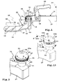
- An example is a module 59 in FIG. 5 drawn, which is mounted or mounted on the bottom 29.
- the evaluation device 58 and / or the module 59 are preferably configured to evaluate signals generated by the sensor 31 and in particular to convert them into relative angle signals, which can then be evaluated by a vehicle electrics of the motor vehicle 12.
- the evaluation device 58 and / or the module 59 have a bus interface, in particular a CAN bus interface, a LIN bus interface or the like.
- Trailer coupling 10b shown substantially corresponds to the trailer coupling 10 or 110, but has a different coupling body 15b and an alternatively configured driver 33b.
- the driver 33b may as in FIG. 13 also illustrated the driver 133 or one of the driver according to the FIGS. 14 to 25 be used.
- the driver 33b is arranged above an equatorial plane 170 of the coupling body 15b.
- the equatorial plane 170 is at the same time the region of the largest outer circumference 175 of the coupling body 15b between its upper side 171 and its underside 172 connected to the coupling body support 13 and the neck section 26 respectively.
- This is essential for a so-called trigger test or lift test, in which it is checked whether the Switzerlandkupplungsability 18 holds on the dome body 15b, when a force acts on the top of the traction coupling 16.
- a guide groove is located farther up, i. further away from the equatorial plane 170 is arranged on a coupling body of a trailer coupling according to the invention.
- a guide groove 47c may be provided which extends in the region of a transverse center plane Q between the upper side 171 and the equatorial plane 170.
- a support surface 173 is provided on the upper side 171.
- the equatorial region 174 ie, the solid part of the dome body 15b is wider.
- an oblique inclination of 10 °, more preferably 15 ° or even 20 °, in particular even 25 ° obliquely to the dome body 15b standing Buchkupplungsability 18 attack on the massive equatorial region 174 of the dome body 15b and finds firm hold, so it can not from the dome body 15b are deducted.
- the dome body 15, 15b may be integral or, of course, may be multi-part, e.g. a bottom 177 and a top 178 (indicated by a dividing line 176, which facilitates, for example, the mounting of the hitch 10b or 110.
- the top 178 is, for example, adhered to the base 177, bolted thereto by means of, for example, a screw 179 or the like.
- guide groove is generally to be understood as a bearing receptacle for supporting a driver.
- the guide groove 47c it is possible for the guide groove 47c to have a section other than a U-shaped cross-section, e.g. having V-shaped cross-section.
- the driver 33b is constructed in several parts. It comprises a carrier 60b, which can be arranged in the guide groove 47b or 47c.
- the carrier 60b forms a ring as a whole, but is composed of a plurality, for example 2, ring segments 81b, 82b. This facilitates in particular the assembly of the carrier 60b in the guide groove 47b, 47c.
- the carrier 60b could also have more segments or be one-piece.
- the carrier 60b has ribs or sliding projections 285 on its sidewalls 283, 284 associated with the sidewalls of the guide groove 47b, which slide along the sidewalls of the guide groove 47b and reduce the friction.
- the ribs or sliding projections 285 are suitably annular.
- a plurality of mutually concentric sliding projections are provided in a driver according to the invention. It is understood that these sliding projections - it can be provided only one - not only on a carrier as the driver 33 b may be provided, but also on another component of an inventively designed driving part.
- a carrier 60b of the carrier 33b has a peripheral wall 86.
- a receptacle 87 serves to hold and receive a compression layer 88 and a driving part 89.
- the compression layer 88 is formed for example by a polyurethane layer or a polyurethane ring, which is arranged at the bottom of the receptacle 87.
- the compression layer 88 is compliant.
- the driving part 89 can be moved radially inward into the receptacle 87, i. that the compression layer 88 then yields.
- the driving part 89 itself can be relatively stiff and / or abrasion resistant. The compliance under the action of a pressure by the Switzerlandkupplungsfact 18 is virtually provided by the compression layer 88.
- the driving part 89 is expediently formed by a toothed belt-like ring, which can be stretched to be fastened to the carrier 60b when the carrier 60b is already fully assembled.
- the entrainment part 89 protrudes radially outward in front of the carrier 60b, so that it is ready for rotational drive through the traction coupling receptacle 18.
- the compression layer 88 is shown relatively thin compared to the driving part 89. It is understood that the compression layer 88 may suitably have a much greater thickness or thickness, so that it is particularly flexible. Precisely because of this, it is possible that the driving part 89 is deformed relatively strong in order to adapt to an inner contour of the Switzerlandkupplungsage 18 and thus can be taken from this as possible without slippage and abrasion.
- a ring segment 81d of a carrier 60d of a driver 33d has, for example, hooks 90d protruding in front of its longitudinal ends, which hooks can be hooked into hook receivers or abutments of a complementary annular segment (not shown in the drawing).
- a donor ring 191 is provided which is, for example, magnet or has individual magnets, not shown.
- the hooks 90d project in front of end faces 192 of the longitudinal ends of the ring segment 81d.
- hooks 90e are provided, which can also engage in receptacles of a complementary, not shown ring segment of the carrier 60e.
- the hooks 90e are not running in the circumferential direction of the ring segment 81e, but protrude in front of upper and / or lower end faces 194 of the ring segment 81e. It is advantageous if one of the hooks 90e on an upper end face 194, the other hooks 90e on a lower end face 194 is arranged so that the hooks 90e engage from opposite sides in recordings on the not shown further ring segment of the driver 33e.
- a clamp 195 which in the present case is designed as a snap ring 196, is used.
- the bracket 195 surrounds both ring segments in any case so far that a largest circumference of the driver 33e is clamped.
- a receptacle 197 for example a depression at the bottom of the receptacle 87, is provided on the ring segments of the carrier 33e.
- a driver 33f its ring segments 81f are made the same, i. It is realized a common part principle.
- locking projections 98f which can engage in corresponding snap-in receptacles 99f on the respective other ring segment 81f.
- the latching projections 98f and the latching receptacles 99f are provided on the respective longitudinal end faces 192.
- the latching projections 98f and the latching receptacles 99f are arranged, for example, on a wall 200 which is located between the peripheral wall 86 and a support wall 201 for supporting the encoder ring 191.
- a respective latching projection 98f comprises, for example, 2 latching arms 202, which are flexible and between which there is a spacing 203, so that they can spring toward each other.
- holding projections 204 can disengage from a corresponding recesses of the locking receptacle 99f.
- a driver 33g substantially corresponds to the driver 33f, wherein at its ring segments 81g slightly modified locking projections 98g are present.
- its locking arms 202 are also spaced apart from each other with a distance 203, but are frontally connected by a connecting element 105 with each other. Nevertheless, the two latching arms 202 spring towards each other to engage in detent receptacles 99g on the other ring segment 81g.
- There are recesses for the retaining projections 204 are present.
- the detent recesses 99g are arranged on a wall 200 which projects radially inwards from the circumferential wall 86.
- a driver 33h substantially corresponds to the driver 33d, but ring segments 81h of the driver 33h follow a common-part principle. Thus, two ring segments 81h can be connected to form an overall ring.
- a hook 90h corresponding to the hook 90d can be hooked into a hook receptacle 106 on the respective other ring segment 81h.
- the hook 90h is so a circumferentially extending hook. Its hook projection protrudes radially inwards, so that it can hook into the hook receptacle 106 arranged, for example, in the bottom area of the receptacle 87 for the snap ring 196 or the receptacle 87 for the entrainment part 89.
- the snap ring 196 or the follower 89, 89p are mounted on the bracket 60h, they press the hook 90h into the hook socket 106 or secure the hook 90h in the hook socket 106.
- a ring segment 81i of a carrier 60i of a driver 33i ( FIG. 19 ) is provided in front of the end faces 192 above, radially inwardly resilient latching projection 98i, which could also be regarded as a hook provided.
- the latching projection 98i springs radially inward to engage in a latching receptacle 99i on the other ring segment 81i.
- the detent recesses 99i are provided on radially inner sides of the peripheral walls 86.
- a respective holding projection 204 protrudes radially outward in front of a latching projection 98i, so that it can engage in a corresponding recess, namely the latching receptacle 99i.
- a driver 33k comprises ring segments 81k, 82k which are hinged together by a hinge 107, for example by a pivot bearing, or as in the embodiment by means of a film hinge.
- a hook 90k which can hook into a hook receptacle 106k on the other ring segment 82k.
- the ring segments 81k and 82k correspond to the ring segment 81h, but are hinged together.
- a positive fit is provided.
- a carrier 60m of a driver 33m substantially corresponds to the carrier 60h, at least as far as the connection of its ring segments 81m by means of hooks 90m, which can be hooked into hook receivers 106.
- an innovative concept for attaching encoders 35m, in the present case, for example, magnets is realized which serve to actuate, for example, the sensor 31.
- the carrier On its inner circumference, the carrier has 60m recordings 110m, for example, pockets or plug-in receptacles, in which the encoder 35m can be inserted.
- the encoders 35m can be locked in the 110m shots.
- the encoders have 35m plug-in projections 111, above which or at which locking recesses 112 are provided.
- the plug-in projections 111 can be inserted through between latching projections 113, which are provided on opposite inner walls of the receptacles 110m, until the latching projections 113 engage in the latching recesses 112.
- a carrier 60o of a driver 33o corresponds approximately to the carrier 60i, at least as far as the concept of hooking or connecting its ring segments 81o is concerned.
- the carrier 60o has receptacles 110o for receiving encoders 35o, for example magnets, or other elements which can generate a field or signal, for example.
- the encoders 35o have on their end faces receptacles 114 which engage in the projections 115 a the respective bottoms of the receptacles 110o and thus provide a firm grip.
- the encoder 35o can be glued into the receptacles 110o. A clamping fit is advantageous.
- An entrainment part 89p is attached to a carrier 60p according to the method of FIG FIG. 22 bolted concept shown.
- the carrier has 60p holes 120, in particular in the micro-thread or the like, which are provided for example at the bottom of the receptacle 87 or other holding contour. Longitudinal ends 83, 84 of the driving part 89 p are penetrated by bolts 122, such as bolts, rivets or the like, in the holes or Recordings 120 penetrate.
- the driving part 89p may be relatively stretchable, for example, include a metal insert. Nevertheless, the driving part 89p is easily mountable on the carrier 60p.
- the carrier 60p may include 2 or more ring segments disposed on and connected to the respective coupling body.
- longitudinal ends 83, 84 of a driving part 89q on a carrier are connected to one another by means of a connecting member 125.
- the connecting member 125 is configured, for example, as a stamped and bent part.
- the connecting member 125 is made of metal, for example, steel sheet, aluminum sheet or the like.
- the link 125 has a base 126 which extends over the respective longitudinal ends 83, 84 of the driving part 89q.
- the base 126 is glued to one longitudinal end 83 or 84. From the base 126 are each at opposite sides of arms 127 from.
- the arms 127 can be bent several times above so that they can engage in recesses between the driving projections 41 or teeth. It is advantageous, the arms 127 and or the base 126, in any case a total of the connecting member 125 form-fitting, for example by means of a grain to connect to the driving part 89q.
Landscapes
- Engineering & Computer Science (AREA)
- Transportation (AREA)
- Mechanical Engineering (AREA)
- Transmission And Conversion Of Sensor Element Output (AREA)
- Mechanical Control Devices (AREA)
Abstract
Description
Die Erfindung betrifft eine Anhängekupplung für ein Kraftfahrzeug, insbesondere ein Personen-Kraftfahrzeug, zum Anhängen eines Anhängers an das Kraftfahrzeug, mit einem an dem Kraftfahrzeug befestigbaren Kuppelkörperträger und einem an einem freien Endbereich des Kuppelkörperträgers angeordneten, insbesondere außenseitig kugelförmigen, Kuppelkörper, auf den eine Zugkupplungsaufnahme einer Zugkupplung des Anhängers aufsetzbar ist, wobei der Kuppelkörper für die Zugkupplungsaufnahme einen diese drehbar lagernden Lagerkörper zum insbesondere mehrachsig drehgelenkigen Schwenken relativ zu dem Kuppelkörperträger bildet, wobei die Anhängekupplung einen an dem Kuppelkörper gelagerten, insbesondere ringförmigen, Mitnehmer aufweist, der von der Zugkupplungsaufnahme mitnehmbar und relativ zu dem Kuppelkörper bewegbar ist und ist und einen Bestandteil einer Sensoranordnung zur Erfassung einer Winkelstellung der Zugkupplung relativ zu dem Kuppelkörperträger bildet.The invention relates to a towing hitch for a motor vehicle, in particular a passenger motor vehicle, for attaching a trailer to the motor vehicle, with a coupling body carrier which can be fastened to the motor vehicle and a coupling body arranged on a free end region of the coupling body carrier, in particular on the outside, onto which a pull-coupling receptacle is attached a coupling of the trailer can be placed, wherein the coupling body for the Zugkupplungsaufnahme a rotatably superimposed bearing body to the particular multi-axis pivotal pivoting relative to the Kuppelkörperträger, wherein the hitch mounted on the coupling body, in particular annular, driver, the entrained by the Zugkupplungsaufnahme and is movable relative to the coupling body and is and forms part of a sensor arrangement for detecting an angular position of the traction coupling relative to the coupling body carrier.
Eine derartige Anhängekupplung ist z.B. in
Die bekannte Anhängekupplung weist einen optischen Sensor auf, der aktiv quasi die Zugkupplungsaufnahme beleuchtet, wobei dieser das Licht zu einem in der Sensoraufnahme angeordneten optischen Sensor reflektiert. Der Sensor erzeugt ein Winkelsignal in Abhängigkeit von einer Winkelstellung der Zugkupplungsaufnahme relativ zum Kuppelkörper, in diesem Fall einer Kupplungskugel.The known trailer coupling has an optical sensor which actively quasi illuminates the Zugkupplungsaufnahme, which reflects the light to an arranged in the sensor receptacle optical sensor. The sensor generates an angle signal as a function of an angular position of the Zugkupplungsaufnahme relative to the coupling body, in this case a coupling ball.
Die Erfassung einer Winkelstellung des Anhängers relativ zum Zugfahrzeug kann für vielfältige Zwecke genutzt werden, beispielsweise um ein Rückwärtseinparken des Gespanns zu erleichtern, um Maßnahmen zur Erhöhung der Fahrstabilität des Gespanns herzustellen oder dergleichen.The detection of an angular position of the trailer relative to the towing vehicle can be used for a variety of purposes, for example, to facilitate Rückwärteinparken the team to make measures to increase the driving stability of the team or the like.
Die zur Winkelerfassung erforderlichen Komponenten sollten an der Anhängekupplung einfach montierbar sein, möglichst auch nachträglich, so dass eine vorhandene Anhängekupplung mit dem Winkelerfassungssystem nachgerüstet werden kann.The components required for angle detection should be easy to install on the trailer hitch, if possible also subsequently, so that an existing hitch can be retrofitted with the angle detection system.
Es ist also die Aufgabe der vorliegenden Erfindung, eine Anhängekupplung mit einem zuverlässigen, insbesondere einfach montierbaren, System zur Winkelerfassung der Zugkupplung relativ zur Anhängekupplung bereitzustellen.It is therefore the object of the present invention to provide a trailer coupling with a reliable, in particular easy to install, system for angle detection of the traction coupling relative to the trailer coupling.
Zur Lösung der Aufgabe ist bei Anhängekupplung der eingangs genannten Art vorgesehen, dass der Mitnehmer einen bezüglich einer Außenoberfläche des Kuppelkörpers weiter innen angeordneten Träger und ein bezüglich der Außenoberfläche des Kuppelkörpers weiter außen an dem Träger angeordnetes Mitnahmeteil zur Mitnahme durch die Zugkupplungsaufnahme umfasst.To solve the problem is provided in trailer coupling of the type mentioned above, that the driver comprises a relative to an outer surface of the coupling body further inside arranged carrier and with respect to the outer surface of the coupling body further outwardly arranged on the carrier driving part for driving through the Zugkupplungsaufnahme.
Der erfindungsgemäße Mitnehmer weist einen z. B. radial oder axial innen bezüglich des Kuppelkörpers angeordneten Träger und ein radial oder axial außen bezüglich des Kuppelkörpers an dem Träger angeordnetes Mitnahmeteil auf, beispielsweise einen Mitnahmering, wobei das Mitnahmeteil zur Mitnahme durch die Zugkupplungsaufnahme vorgesehen ist.The driver according to the invention has a z. B. radially or axially inside with respect to the coupling body arranged carrier and a radially or axially outside relative to the coupling body on the carrier arranged driving part on, for example, a driving ring, wherein the driving part is provided for driving through the Zugkupplungsaufnahme.
Während der Träger zweckmäßigerweise am Kuppelkörper verbleibt, kann das Mitnahmeteil ausgetauscht werden. Es versteht sich, dass mehrere Mitnahmeteile vorgesehen sein können, d.h. nicht nur ein Mitnahmeteil.While the carrier expediently remains on the dome body, the driving part can be replaced. It is understood that a plurality of driving parts can be provided, ie not just a driving part.
Das Mitnahmeteil steht zweckmäßigerweise vor eine Außenoberfläche, z.B. eine Kugeloberfläche, des Kuppelkörpers nach außen vor. Der Träger hingegen steht zweckmäßigerweise nicht vor eine Außenoberfläche des Kuppelkörpers nach außen vor - wobei dies durchaus möglich wäre. Es ist prinzipiell auch möglich, dass das Mitnahmeteil nicht vor eine Außenoberfläche, z.B. eine Kugeloberfläche, des Kuppelkörpers nach außen vorsteht. In diesem Fall könnte beispielsweise ein in einen Innenraum der Zugkupplungsaufnahme vorstehender Vorsprung der Zugkupplung des Anhängers mit dem Mitnahmeteil in Eingriff gelangen.The entrainment part is expediently located in front of an outer surface, e.g. a spherical surface, the dome body outwards. The carrier, on the other hand, is expediently not projecting outwards in front of an outer surface of the dome body - although this would be quite possible. It is also possible in principle that the entrainment part is not in front of an outer surface, e.g. a spherical surface, the coupling body protrudes outward. In this case, for example, a projecting into an interior of the Zugkupplungsaufnahme projection of the traction coupling of the trailer could engage with the driving part.
Es versteht sich, dass der Träger auch Abschnitte aufweisen kann, die beispielsweise zur Außenoberfläche des Kuppelkörpers vorstehen, beispielsweise Abschnitte, zwischen denen das Mitnahmeteil angeordnet ist. Weiterhin ist es auch möglich, dass am Träger insbesondere innen bezüglich der Außenoberfläche des Kuppelkörpers noch weitere Bauteile angeordnet sind, so dass beispielsweise der Träger mit einem Gleitring oder einem sonstigen Gleitkörper versehen ist, mit dem der Träger am Kuppelkörper beweglich, insbesondere drehbeweglich oder schiebebeweglich, gelagert ist.It is understood that the carrier may also have portions that protrude, for example, to the outer surface of the coupling body, for example, portions between which the driving part is arranged. Furthermore, it is also possible for further components to be arranged on the carrier, in particular with respect to the outer surface of the coupling body, so that, for example, the carrier is provided with a sliding ring or another sliding body, with which the carrier is movable, in particular rotationally movable or slide-movable, on the coupling body. is stored.
Das erfindungsgemäße Konzept ist beispielsweise bei einem ringförmigen Mitnehmer anwendbar. Der Mitnehmer ist beispielsweise drehbar an dem Kuppelkörper gelagert. Aber auch verschieblichen Mitnehmer können nach dem erfindungsgemäßen Konzept aufgebaut sein. Der Mitnehmer ist beispielsweise linear verschieblich an dem Kuppelkörper gelagert und kann von der Zugkupplungsaufnahme verschoben werden, beispielsweise linear.The inventive concept is applicable for example in an annular driver. The driver is for example rotatably mounted on the coupling body. But slidable driver can be constructed according to the concept of the invention. The driver is for example mounted linearly displaceable on the coupling body and can be moved from the Zugkupplungsaufnahme recording, for example, linear.
Das Mitnahmeteil selbst ist als ein auswechselbares Bauteil ausgestaltet, so dass es bei Verschleiß entfernt und am Träger ein unverschlissenes Mitnahmeteil befestigbar ist.The driving part itself is designed as a replaceable component, so that it is removed when worn and the wearer an unworn driving part can be fastened.
Das Mitnahmeteil ist vorteilhaft mit dem Träger verrastbar und/oder verklemmbar und/oder verklebt.The driving part is advantageously latched to the carrier and / or clamped and / or glued.
Es ist auch möglich, dass Komponenten des Mitnehmers, z.B. Komponenten des Mitnahmeteils und/oder des Trägers, und/oder das Mitnahmeteil mit dem Träger, miteinander verschweißt sind, z.B. mittels Ultraschallschweißens.It is also possible that components of the driver, e.g. Components of the driving part and / or the carrier, and / or the driving part with the carrier, are welded together, e.g. by ultrasonic welding.
Es ist z.B. möglich, dass an dem Mitnahmeteil eine Klebeschicht angeordnet ist, die vorteilhaft durch eine Schutzfolie abgedeckt ist. Nach Abziehen der Schutzfolie liegt die Klebeschicht frei und das Mitnahmeteil kann auf den Träger aufgeklebt werden.It is e.g. possible that an adhesive layer is disposed on the driving part, which is advantageously covered by a protective film. After removing the protective film, the adhesive layer is exposed and the driving part can be glued to the carrier.
Bevorzugt sind am Träger und/oder am Mitnahmeteil Montagekodierungen, insbesondere Drehwinkelkodierungen vorhanden, so dass das Mitnahmeteil am Träger nur in einer vorbestimmten Montageposition, beispielsweise Drehwinkelposition, montierbar ist. Die Montagekodierungen umfassen beispielsweise zueinander passende Kodier-Vorsprünge und Kodier-Aufnahmen am Träger und am Mitnahmeteil oder umgekehrt. Eine Montagekodierung kann auch eine Poka Yoke sein oder als solche bezeichnet werden.Preferably, mounting codings, in particular rotational angle codings, are present on the carrier and / or on the driving part, so that the driving part can be mounted on the carrier only in a predetermined assembly position, for example rotational angle position. The mounting codings comprise, for example, mutually matching coding projections and coding receptacles on the carrier and on the driving part or vice versa. A Montagekodierung can also be a Poka Yoke or be designated as such.
Der Träger kann beispielsweise mehrteilig sein, beispielsweise zweiteilig. Der Träger umfasst beispielsweise miteinander verbundene Träger- oder Ringsegmente. Die Verbindung des Trägers miteinander kann auch durch das Mitnahmeteil erfolgen.The carrier may for example be multi-part, for example in two parts. The carrier comprises, for example, interconnected carrier or ring segments. The connection of the carrier with each other can also be done by the driving part.
Vorteilhaft ist es, wenn die Träger- oder Ringsegmente des Trägers miteinander direkt verbunden sind, beispielsweise durch Rastvorsprünge, Haken oder dergleichen. Es versteht sich, dass die Ringsegmente auch miteinander verklebt oder verschweißt sein können.It is advantageous if the carrier or ring segments of the carrier are directly connected to each other, for example by latching projections, hooks or the like. It is understood that the ring segments can also be glued or welded together.
Besonders bevorzugt ist eine Rastverbindung oder Hakenverbindung zwischen Träger und Mitnahmeteil. Beispielsweise können das oder die Mitnahmeteile Rastvorsprünge oder Hakenvorsprünge oder beides aufweisen, die in korrespondierende Rastaufnahmen oder Hakenaufnahmen am Träger oder einem Trägersegment einrastbar bzw. einhakbar sind. Es versteht sich, dass auch umgekehrt am Träger Rastvorsprünge oder Rasthaken vorgesehen sein können, die in entsprechende Rastaufnahmen oder Hakenaufnahmen an dem Mitnahmeteil oder den Mitnahmeteilen eingreifen.Particularly preferred is a locking connection or hook connection between the carrier and driving part. For example, the or the entrainment parts have latching projections or hook projections or both, which can be latched or hooked into corresponding latching receivers or hook receivers on the carrier or a carrier segment. It is understood that, conversely, latching projections or latching hooks can also be provided on the carrier, which engage in corresponding latching receptacles or hook receptacles on the driving part or the entrainment parts.
Der Träger weist beispielsweise eine Aufnahme für das Mitnahmeteil auf. Die Aufnahme ist beispielsweise als eine Ringnut ausgestaltet.The carrier has, for example, a receptacle for the driving part. The receptacle is designed, for example, as an annular groove.
Eine bevorzugte Ausführungsform der Erfindung sieht vor, dass der Träger in einer Lageraufnahme des Kuppelkörpers beweglich gelagert ist und Lagerflächen zur Lagerung in der Lageraufnahme aufweist. Das Mitnahmeteil ist zweckmäßigerweise zwischen den Lagerflächen, beispielsweise Seitenwänden, des Trägers aufgenommen, hat jedoch keinen Berührkontakt mit der Lageraufnahme des Kuppelkörpers. Somit kann beispielsweise ein Träger aus einem relativ harten, gleitfähigem Material verwendet werden, während das Mitnahmeteil oder die Mitnahmeteile, die eher für einen Reibschluss oder Formschluss ausgelegt sind, keine Berührung mit der Lageraufnahme haben.A preferred embodiment of the invention provides that the carrier is movably mounted in a bearing receptacle of the coupling body and has bearing surfaces for mounting in the bearing receptacle. The entrainment part is expediently received between the bearing surfaces, for example side walls, of the carrier, but has no contact with the bearing receptacle of the coupling body. Thus, for example, a carrier made of a relatively hard, lubricious material may be used, while the driving part or the driving parts, which are designed for a frictional engagement or positive locking rather, have no contact with the bearing support.
Weiterhin ist es vorteilhaft, wenn am Träger und Mitnahmeteil kooperierende Drehmitnahmemittel, z.B. mindestens ein Drehmitnahmevorsprung am einen Bauteil (Träger oder Mitnahmeteil), der in eine Drehmitnahmeaufnahme am andern Bauteil (Mitnahmeteil oder Träger) eingreift, vorgesehen sind.Furthermore, it is advantageous when cooperating on the carrier and driving part rotary driving means, e.g. at least one rotational driving projection on one component (carrier or driving part), which engages in a rotary driving receptacle on the other component (driving part or carrier), are provided.
Zwischen dem Mitnahmeteil und dem Träger oder am Mitnahmeteil und/oder am Träger ist zweckmäßigerweise eine Kompressionsschicht vorgesehen. Die Kompressionsschicht besteht oder enthält ein leicht komprimierbares Material, zum Beispiel Polyurethan. Beispielsweise ist die Kompressionsschicht am Boden der Aufnahme für das Mitnahmeteil vorgesehen. Die Kompressionsschicht kann einen Bestandteil des Trägers und/oder des Mitnahmeteils bilden oder vom Träger und Mitnahmeteil separat sein.Between the driving part and the carrier or on the driving part and / or on the carrier a compression layer is expediently provided. The compression layer is or contains an easily compressible material, for example polyurethane. For example, the compression layer is at the bottom of the receptacle intended for the driving part. The compression layer may form part of the carrier and / or the entrainment part or be separate from the carrier and entrainment part.
Die Kompressionsschicht ist radial nachgiebig, so dass das Mitnahmeteil unter Komprimierung der Kompressionsschicht in Richtung des Trägers verformbar ist, also nachgibt. Bei dieser Konstruktion können beispielsweise der Träger und das Mitnahmeteil relativ hart und/oder biegesteif sein, also verschleißfest. Die Nachgiebigkeit ist vorzugsweise im Innern des Mitnehmers vorgesehen, zwischen dem Träger und dem Mitnahmeteil.The compression layer is radially yielding, so that the entrainment member is deformable in compression of the compression layer in the direction of the carrier, that gives way. In this construction, for example, the carrier and the driving part can be relatively hard and / or rigid, so wear-resistant. The compliance is preferably provided in the interior of the driver, between the carrier and the driving part.
Das Mitnahmeteil besteht beispielsweise aus einem relativ abriebfesten Material, z.B. aus einer insbesondere 2mm starken PU Folie in 85 Shore A oder bis zu 95 Shore A mit großen Reißdehnung, zum Beispiel größer als 400-500, insbesondere größer als 600. Eine weitere Lage des Mitnahmeteils kann beispielsweise aus Sylomer bestehen oder ein solches Material umfassen.The driving part consists for example of a relatively abrasion-resistant material, e.g. from a particular 2mm thick PU film in 85 Shore A or up to 95 Shore A with high elongation at break, for example greater than 400-500, in particular greater than 600. Another position of the driving part may for example consist of Sylomer or comprise such a material.
Der Mitnehmer, insbesondere das Mitnahmeteil, ist zweckmäßigerweise riemenartig oder umfasst einen Riemen.The driver, in particular the driving part is expediently belt-like or comprises a belt.
Bevorzugt hat der Mitnehmer, insbesondere das Mitnahmeteil, nach außen, insbesondere radial außen, vorstehende Mitnahmevorsprünge und/oder eine Reibschlussfläche.Preferably, the driver, in particular the driving part, to the outside, in particular radially outside, protruding driving projections and / or a Reibschlussfläche.
Die Mitnahmevorsprünge sind zweckmäßigerweise flexibel oder elastisch oder beides. Somit können die Mitnahmevorsprünge durch die Zugkupplung, insbesondere die Zugkupplungsaufnahme, verformt werden, so dass sie flexibel und elastisch an deren Innenoberfläche anliegen.The driving projections are expediently flexible or elastic or both. Thus, the driving projections can be deformed by the traction coupling, in particular the Zugkupplungsaufnahme, so that they rest flexibly and elastically on the inner surface.
Die Mitnahmevorsprünge, auch in nicht elastischer Ausführung, und/oder ebenfalls vorteilhafte Schlitze am Mitnahmeteil haben auch den Vorteil, dass Verschmutzungen, z.B. Sand, Dreck oder sonstige Materialien, zwischen die Mitnahmevorsprünge gelangen können und so keine direkte Kraft auf im Innern des Mitnehmers befindliche Komponenten, z.B. die nachfolgend noch beschriebenen Magnete, ausüben können. Beispielsweise ist der Mitnehmer geschlitzt, so dass dadurch Mitnahmevorsprünge gebildet sind. Eine an sich eigenständige Erfindung, insbesondere in Verbindung mit den Merkmalen des Oberbegriffs des Anspruchs 1, stellt die nachfolgende Ausführungsform dar. Bei dieser Ausführungsform muss der Mitnehmer selbstverständlich nicht mehrteilig sein, muss jedenfalls nicht aus einem Träger und einem Mitnahmeteil bestehen, sondern kann beispielsweise auch insgesamt einstückig sein oder teilweise einstückig sein, z.B. radial und/oder in Umfangsrichtung. Eine Kombination dieser Ausführungsform mit anderen oben oder weiter unten beschriebenen Maßnahmen ist möglich.The driving projections, even in non-elastic design, and / or also advantageous slots on the driving part also have the advantage that contamination, such as sand, dirt or other materials, can get between the driving projections and so no direct force on the inside of the driver located components, such as the magnets described below, can exercise. For example, the driver is slotted, thereby driving lugs are formed. A self-contained invention, in particular in conjunction with the features of the preamble of claim 1, represents the following embodiment. In this embodiment, of course, the driver does not have to be multi-part, in any case does not have to consist of a carrier and a driving part, but may, for example be in one piece or be partially in one piece, eg radially and / or circumferentially. A combination of this embodiment with other measures described above or below is possible.
Der Mitnehmer, insbesondere das Mitnahmeteil, haben zweckmäßigerweise mindestens einen Mitnahmevorsprung oder mindestens eine Mitnahmevertiefung, die zum formschlüssigen Eingriff in eine passende Gegenkontur oder mit einer passenden Gegenkontur der Zugkupplung vorgesehen sind, beispielsweise in eine korrespondierende Mitnahmevertiefung oder für einen Mitnahmevorsprung der Zugkupplung. Bevorzugt ist es beispielsweise, wenn mindestens eine Mitnahmevertiefung für eine Haltebacke der Zugkupplung vorhanden ist. Es versteht sich, dass vorteilhaft mehrere derartige Mitnahmevertiefungen in definierten Winkelabständen über einen Außenumfang des Mitnehmers vorhanden sind, so dass in definierten Positionen eine Mitnahmekopplung zwischen dem Mitnehmer und der Zugkupplung möglich ist, insbesondere eine Drehmitnahme.The driver, in particular the entrainment part, expediently have at least one entrainment projection or at least one entrainment depression, which are provided for the positive engagement in a matching mating contour or with a matching mating contour of the traction coupling, for example in a corresponding driving recess or for a driving projection of the traction coupling. It is preferred, for example, if at least one driving recess for a holding jaw of the traction coupling is present. It is understood that advantageously several such driving recesses are provided at defined angular intervals over an outer circumference of the driver, so that in defined positions a driving coupling between the driver and the traction clutch is possible, in particular a rotational drive.
Die Mitnahmevertiefung ist beispielsweise durch einen Bereich zwischen Mitnahmevorsprüngen vorgesehen, die zum reibschlüssigen und/oder formschlüssigen Kontakt mit der Zugkupplung vorgesehen sind.The driving recess is provided for example by a region between driving projections, which are provided for frictional and / or positive contact with the traction coupling.
Die Mitnahmevertiefung oder die Mitnahmevorsprünge haben zweckmäßigerweise Verstärkungen, beispielsweise verstärkte Randbereiche, so dass eine Beschädigung beispielsweise durch die vorgenannte Haltebacke der Zugkupplung vermieden wird.The entrainment recess or the entrainment projections advantageously have reinforcements, for example reinforced edge regions, so that damage, for example, by the abovementioned holding jaw of the traction coupling is avoided.
Die nachfolgenden Ausführungen beziehen sich auf ein bevorzugtes Mitnahmeteil, das besonders einfach austauschbar an einem Träger angeordnet ist.The following statements relate to a preferred driving part, which is particularly easily interchangeable disposed on a support.
Das Mitnahmeteil weist zweckmäßigerweise einen lang gestreckten, biegeflexiblen Körper auf oder ist dadurch gebildet und kann an die Außenkontur des Trägers angepasst werden. Somit ist es ohne weiteres an dem bereits am Kuppelkörper montierten Träger lösbar verbindbar. Der biegeflexible Körper hat also vorzugsweise ein erstes Längsende und ein zweites Längsende.The driving part expediently has an elongated, flexurally flexible body or is formed thereby and can be adapted to the outer contour of the carrier. Thus, it is readily releasably connectable to the already mounted on the dome body carrier. The flexurally flexible body therefore preferably has a first longitudinal end and a second longitudinal end.
Bevorzugt ist es, wenn der Träger eine Aufnahme, zum Beispiel eine Steckaufnahme, aufweist, in der ein Endbereich des Mitnahmeteils, insbesondere des vorgenannten lang gestreckten Mitnahmeteils, aufgenommen ist. Die Aufnahme kann beispielsweise nach radial außen am Träger offen sein, so dass der Endbereich des Mitnahmeteils von radial außen her in die Aufnahme eingesteckt werden kann. Es ist aber auch möglich, dass die Aufnahme beispielsweise eine tangential oder in einem Winkel zwischen einer Tangente und einer Radiallinie offene Aufnahme ist, so dass der Endbereich des Mitnahmeteils beispielsweise schräg bezüglich einer Radiallinie bzw. einer Tangente eingesteckt werden kann. Bevorzugt ist an der Aufnahme mindestens eine Wandung vorhanden, die bei montiertem Mitnahmeteil und Gebrauch der Anhängekupplung zwischen dem Mitnahmeteil und der Zugkugelkupplung oder einem Außenumfang des Mitnahmeteils angeordnet ist.It is preferred if the carrier has a receptacle, for example a plug-in receptacle, in which an end region of the entrainment part, in particular of the aforementioned elongate entrainment part, is accommodated. The receptacle may, for example, be open radially on the outside of the carrier, so that the end region of the entrainment part can be inserted into the receptacle from radially outward. But it is also possible that the recording is, for example, a tangent or open at an angle between a tangent and a radial line recording, so that the end portion of the driving part can be inserted, for example, obliquely with respect to a radial line or a tangent. Preferably, at least one wall is provided on the receptacle, which is arranged when the driving part is mounted and the trailer coupling is used between the driving part and the ball coupling or an outer circumference of the driving part.
Die Aufnahme für den Endbereich des Mitnahmeteils hat zweckmäßigerweise mindestens eine Hakenvertiefung, Rastvertiefungen oder dergleichen andere Hakenverbindungsmittel oder Rastverbindungsmittel, alternativ oder ergänzend auch Klemm-Verbindungsmittel, zum festen Halt des Endbereich des Mitnahmeteils in der Aufnahme.The receptacle for the end portion of the driving part expediently has at least one hook recess, latching recesses or the like other hook connecting means or latching connection means, alternatively or additionally also clamping connection means for firmly holding the end portion of the driving part in the receptacle.
Der Mitnehmer, insbesondere das Mitnahmeteil, ist vorzugsweise in der Art eines Zahnriemens ausgestaltet.The driver, in particular the driving part, is preferably designed in the manner of a toothed belt.
Der Zahnriemen kann zum Beispiel ein ringförmiger Zahnriemen sein. Besonders bevorzugt ist jedoch, wenn der Zahnriemen ein biegeflexibler Riemen ist, der eine Längsgestalt aufweist und somit an die Außenkontur des Trägers anpassbar ist und mit dem bereits am Kuppelkörper montierten Träger lösbar verbindbar ist.The toothed belt may be, for example, an annular toothed belt. However, it is particularly preferred if the toothed belt is a flexurally flexible belt which has a longitudinal shape and thus can be adapted to the outer contour of the carrier and can be releasably connected to the carrier already mounted on the dome body.
Der Mitnehmer und/oder ein Lagerbereich des Kuppelkörpers zum Lagern des Mitnehmers sind zweckmäßigerweise mit einer Gleitbeschichtung oder einer Gleitlage versehen. Dadurch ist das Drehen des Mitnehmers an dem Kuppelkörper erleichtert.The driver and / or a storage area of the coupling body for supporting the driver are expediently provided with a sliding coating or a sliding layer. As a result, the rotation of the driver on the coupling body is facilitated.
Bezüglich der Sensoranordnung sind verschiedene Techniken möglich:
- Der Mitnehmer umfasst vorteilhaft mindestens einen Sensor und/oder mindestens einen Geber zum Betätigen des mindestens einen Sensors, insbesondere eine Magnetanordnung mit mindestens einem Magneten und/oder einen optischen Geber, insbesondere eine Reflexionsmarkierung, und/oder ein magnetisiertes Kunststoffmaterial mit magnetischen Partikeln.
- The driver advantageously comprises at least one sensor and / or at least one sensor for actuating the at least one sensor, in particular a magnet arrangement with at least one magnet and / or an optical encoder, in particular a reflection marking, and / or a magnetized plastic material with magnetic particles.
Beispielsweise ist mindestens ein Sensor, zum Beispiel ein optischer Sensor, ein induktiver oder magnetischer Sensor oder dergleichen ortsfest am Kuppelkörper, beispielsweise in der Sensoraufnahme, angeordnet, während einer oder mehrere Geber an dem Mitnehmer angeordnet sind. Es ist aber prinzipiell auch möglich, dass beispielsweise ein Sensor am Mitnehmer angeordnet ist, der von einem ortsfest am Kuppelkörper, zum Beispiel in derFor example, at least one sensor, for example an optical sensor, an inductive or magnetic sensor or the like, is arranged fixedly on the coupling body, for example in the sensor receptacle, while one or more sensors are arranged on the driver. But it is in principle also possible that, for example, a sensor is arranged on the driver, of a stationary on the dome body, for example in the
Sensoraufnahme, angeordneten Geber betätigbar ist. Bei dem Geber handelt es sich beispielsweise um eine Lichtquelle, einen Magneten, oder dergleichen.Sensor recording, arranged encoder is actuated. The transmitter is, for example, a light source, a magnet, or the like.
Bevorzugt ist ein magnetisches Prinzip, d.h. der Sensor umfasst einen oder mehrere Sensorkomponenten, die magnetisch aktivierbar sind. Beispielsweise handelt es sich bei dem Sensor um einen magnetisch resistiven Sensor, insbesondere einen GMR- oder AMR-Sensor. Es versteht sich, dass die Erfindung nicht auf magnetische Sensoren beschränkt ist, d.h. dass beispielsweise auch optische Sensoren möglich sind, was später noch deutlich wird.Preferably, a magnetic principle, i. the sensor comprises one or more sensor components that are magnetically activated. By way of example, the sensor is a magnetoresistive sensor, in particular a GMR or AMR sensor. It is understood that the invention is not limited to magnetic sensors, i. that, for example, optical sensors are possible, which will become clear later.
In Zusammenwirkung mit dem magnetischen Sensor und der magnetischen Sensoranordnung weist der Mitnehmer zweckmäßigerweise eine Magnetanordnung mit einem oder mehreren Magneten auf. Wenn mehrere Magnete vorhanden sind, sind ihre Pole zweckmäßigerweise in Umfangsrichtung des Mitnehmers zueinander beabstandet. Beispielsweise sind mehrere Magnete, insbesondere zwei oder mehr Magnete, in Umfangsrichtung hintereinander angeordnet, wobei die Polarität der Magnete zweckmäßigerweise gleich orientiert ist, d.h. dass ein Südpol des einen Magneten neben einem Nordpol des benachbarten Magneten angeordnet ist. Es versteht sich, dass jedoch auch eine umgekehrte Magnetisierung möglich ist, d.h. dass einander gegenüberliegende Südpole oder Nordpole vorgesehen sind. Weiterhin ist es denkbar, einen ringförmigen Magneten vorzusehen.In cooperation with the magnetic sensor and the magnetic sensor arrangement, the driver expediently has a magnet arrangement with one or more magnets. If several magnets are present, their poles are expediently spaced from each other in the circumferential direction of the driver. For example, a plurality of magnets, in particular two or more magnets, arranged in the circumferential direction one behind the other, wherein the polarity of the magnets are expediently the same orientation, i. that a south pole of the one magnet is arranged adjacent to a north pole of the adjacent magnet. It will be understood, however, that reverse magnetization is also possible, i. that opposite south poles or north poles are provided. Furthermore, it is conceivable to provide an annular magnet.
Der Mitnehmer umfasst zweckmäßigerweise mindestens eine Sensorteilaufnahme, vorteilhaft eine Anordnung von Sensorteilaufnahmen, die zum Aufnehmen mindestens eines Gebers, zum Beispiel eines Magneten, oder zur Aufnahme eines Sensors ausgestaltet sind. Diese mindestens eine Sensorteilaufnahme ist zweckmäßigerweise an einem Innenumfang des Mitnehmers angeordnet. Beispielsweise ist die mindestens eine Sensorteilaufnahme als Steckaufnahme oder Tasche ausgestaltet. Somit können der Geber oder der Sensor in eine jeweilige Steckaufnahme eingesteckt werden. Bevorzugt sind Rastmittel zum Verrasten des jeweiligen Gebers oder Sensors in der Sensorteilaufnahme des Mitnehmers vorgesehen. Bevorzugt ist es, dass der Geber oder Sensor auswechselbar am Mitnehmer aufgenommen ist. An dieser Stelle sei bemerkt, dass selbstverständlich ein Geber oder Sensor auch fest mit dem Mitnehmer verbunden sein kann, beispielsweise verklebt oder in ein Material des Mitnehmers eingegossen oder eingebettet sein kann.The driver expediently comprises at least one sensor part receptacle, advantageously an arrangement of sensor part receptacles which are designed to receive at least one transmitter, for example a magnet, or to receive a sensor. This at least one sensor sub-receptacle is expediently arranged on an inner circumference of the driver. For example, the at least one sensor part receptacle is designed as a plug-in receptacle or pocket. Thus, the encoder or the sensor in a each plug-in receptacle are inserted. Preferably, latching means are provided for latching the respective transmitter or sensor in the sensor part receiver of the driver. It is preferred that the encoder or sensor is interchangeable received on the driver. It should be noted that, of course, a donor or sensor can also be firmly connected to the driver, for example glued or cast in a material of the driver or can be embedded.
Des Weiteren kann der Mitnehmer auch aus einem magnetischen Kunststoffmaterial oder einem magnetisierbaren Kunststoffmaterial bestehen oder ein solches Kunststoffmaterial aufweisen.Furthermore, the driver can also consist of a magnetic plastic material or a magnetizable plastic material or comprise such a plastic material.
Es ist aber auch möglich, dass der Mitnehmer einen optischen Geber, z.B. eine Reflektionsmarkierung, einen Strichcode oder dergleichen aufweist, mit der der Sensor, in diesem Fall ein optischer Sensor, zusammenwirkt.But it is also possible that the driver an optical encoder, e.g. a reflection mark, a bar code or the like, with which the sensor, in this case an optical sensor, cooperates.
Die Magnetisierung des Mitnehmers oder eines Teils desselben kann beispielsweise anhand von magnetischem Material, z.B. Metallsplittern, seltenen Erden oderdergleichen, erfolgen.The magnetization of the driver or a part thereof can be determined, for example, from magnetic material, e.g. Metal splinters, rare earths or the like, take place.
Der Mitnehmer, insbesondere der Träger, weist zweckmäßigerweise mindestens eine Sensorteilaufnahme zur Aufnahme eines Sensorgebers oder eines Sensorelements auf. Bevorzugt ist diese Sensorteilaufnahme oder Anordnung von Sensorteilaufnahmen durch einen Deckel oder eine Deckelanordnung verschließbar. Der Deckel kann gleichzeitig auch ein Lagerelement bilden oder eine Lagerfläche zur Lagerung in einer Lageraufnahme am Kuppelkörper bereitstellen.The driver, in particular the carrier, expediently has at least one sensor part receptacle for receiving a sensor transmitter or a sensor element. Preferably, this sensor part receptacle or arrangement of sensor part receptacles can be closed by a cover or a cover arrangement. At the same time, the cover can also form a bearing element or provide a bearing surface for mounting in a bearing receptacle on the coupling body.
Eine an sich eigenständige Erfindung, insbesondere in Verbindung mit den Merkmalen des Oberbegriffs des Anspruchs 1, stellt die nachfolgende Ausführungsform dar. Bei dieser Ausführungsform muss der Mitnehmer selbstverständlich nicht mehrteilig sein, muss jedenfalls nicht aus einem Träger und einem Mitnahmeteil bestehen, sondern kann beispielsweise auch insgesamt einstückig sein oder teilweise einstückig sein, z.B. radial und/oder in Umfangsrichtung. Eine Kombination dieser Ausführungsform mit anderen oben oder weiter unten beschriebenen Maßnahmen ist möglich.A self-contained invention, in particular in conjunction with the features of the preamble of claim 1, represents the following embodiment. In this embodiment, the driver must of course not be multi-part, must in any case not consist of a carrier and a driving part, but may for example also be a total of one piece or partially in one piece, for example, radially and / or in the circumferential direction. A combination of this embodiment with other measures described above or below is possible.
Eine bevorzugte Ausführungsform der Erfindung sieht nämlich vor, dass der Mitnehmer, insbesondere der Träger, eine Reihe entlang einer Reihenlinie nebeneinander angeordneter Sensorteilaufnahmen für Sensorgeber oder Sensorelemente (oder beides) aufweist, in denen ein Einsteckkörper mit mehreren Sensorgebern und/oder Sensorelementen angeordnet ist. Die Sensorteilaufnahme kann auch eine langgestreckte Gestalt haben, so dass auch eine einzige, langgestreckte Sensorteilaufnahme ausreicht, in die der Einsteckkörper eingesteckt werden kann. Der Einsteckkörper kann beispielsweise seinerseits flexibel sein, so dass er an eine Ringform des Trägers (wenn dieser als Ring ausgestaltet ist) anpassbar ist. In oder an dem Einsteckkörper sind die Sensorgeber oder Sensorelemente entlang der Reihenlinie angeordnet. Es ist auch möglich, dass der Einsteckkörper die Sensorgeber integral bildet. Beispielsweise kann der Einsteckkörper aus einem magnetisierbaren Kunststoff bestehen, d.h. aus einer Kunststoffmaterial, das beispielsweise Eisenfeilspäne oder andere magnetisierbare Komponenten enthält. Bevorzugt ist es, wenn die Sensorgeber, beispielsweise Magnete, abwechselnd, d.h. mit unterschiedlicher Polarität, polarisiert sind.Namely, a preferred embodiment of the invention provides that the driver, in particular the carrier, has a row along a row of juxtaposed sensor component holders for sensor sensors or sensor elements (or both), in which a plug-in body with a plurality of sensor sensors and / or sensor elements is arranged. The sensor part receptacle can also have an elongated shape, so that a single, elongated sensor part receptacle is sufficient, in which the male body can be inserted. The plug-in body, for example, in turn be flexible, so that it is adaptable to an annular shape of the carrier (if this is designed as a ring). In or on the plug-in body, the sensor sensors or sensor elements are arranged along the row line. It is also possible that the male body integrally forms the sensor body. For example, the male body may be made of a magnetizable plastic, i. from a plastic material containing, for example, iron filings or other magnetizable components. It is preferred if the sensors, for example magnets, are alternately, i. with different polarity, are polarized.
Der Kuppelkörper weist vorteilhaft eine Sensoraufnahme auf, in der eine Komponente einer Sensoranordnung, insbesondere mindestens ein Sensor, zur Erfassung einer Winkelstellung der Zugkupplung relativ zu dem Kuppelkörperträger angeordnet oder anordenbar ist.The dome body advantageously has a sensor receptacle in which a component of a sensor arrangement, in particular at least one sensor, for detecting an angular position of the traction coupling is arranged or can be arranged relative to the dome body carrier.
Beispielsweise ist mindestens ein Sensor, zum Beispiel ein optischer Sensor, ein induktiver oder magnetischer Sensor oder dergleichen, ortsfest am Kuppelkörper, beispielsweise in der Sensoraufnahme, angeordnet, während einer oder mehrere Geber an dem Mitnehmer angeordnet sind. Es ist aber prinzipiell auch möglich, dass beispielsweise ein Sensor am Mitnehmer angeordnet ist, der von einem ortsfest am Kuppelkörper, zum Beispiel in der Sensoraufnahme, angeordneten Geber betätigbar ist. Bei dem Geber handelt es sich beispielsweise um eine Lichtquelle, einen Magneten, oder dergleichen.For example, at least one sensor, for example an optical sensor, an inductive or magnetic sensor or like, fixed to the dome body, for example, in the sensor receptacle, arranged while one or more encoders are arranged on the driver. But it is in principle also possible that, for example, a sensor is arranged on the driver, which is operable by a stationary on the coupling body, for example in the sensor holder, arranged encoder. The transmitter is, for example, a light source, a magnet, or the like.
Bei dem am Kuppelkörper angeordneten Mitnehmer sind die folgenden Maßnahmen zweckmäßig:
- Es ist vorteilhaft, wenn der Mitnehmer, insbesondere der Träger, einen Ring umfasst, der mehrere Ringsegmente aufweist. Der Mitnehmer, z.B. der Träger und/oder das Mitnahmeteil, ist vorteilhaft in Umfangsrichtung mehrteilig, zumindest in einer Radialebene, d.h. dass er in mindestens einer Radialebene oder insgesamt beispielsweise 2 oder mehr Ringsegmente umfasst.
- It is advantageous if the driver, in particular the carrier, comprises a ring which has a plurality of ring segments. The driver, for example, the carrier and / or the entrainment member is advantageously in several parts in the circumferential direction, at least in a radial plane, ie that it comprises at least one radial plane or a total of, for example, 2 or more ring segments.
Segmente des Mitnehmers, d.h. des Trägers und/oder des Mitnahmeteils, insbesondere Ringsegmente, können beispielsweise durch einmal verschließbare Verbindungen miteinander verbunden sein, z.B. Tannenbaumschrägen, Clipse oder dergleichen. Beispielsweise ist eine Verbindung der Segmente des Mitnehmers oder Trägers in der Art von Kabelbinder-Verbindungen möglich. Aber auch sonstige Fügemethoden, z.B. Vernieten, Schrauben, Kleben, miteinander Verclipsen oder Verrasten oder dergleichen sind bei Segmenten eines erfindungsgemäßen Mitnehmers ohne Weiteres möglich. Es ist auch möglich, dass Teile eines erfindungsgemäßen Mitnehmers mittels eines Gelenkes und/oder eines Filmscharniers miteinander verbunden sind.Segments of the driver, i. the carrier and / or the entrainment part, in particular ring segments, may be connected to each other, for example by once-closable connections, e.g. Tannenbaumschrägen, clips or the like. For example, a connection of the segments of the driver or carrier in the manner of cable tie connections is possible. But also other joining methods, e.g. Riveting, screwing, gluing, clipping together or latching together or the like are readily possible with segments of a driver according to the invention. It is also possible that parts of a driver according to the invention are interconnected by means of a hinge and / or a film hinge.
Mitnahmeteilsegmente oder Trägersegmente, z.B. Ringsegmente, eines Mitnehmers gemäß der Erfindung können beispielsweise miteinander verklammert werden. Auch ein Verschrauben oder Verhaken ist ohne weiteres möglich. Es ist auch möglich, dass bei einem mindestens zwei oder mehrere Radiallagen umfassenden Mitnehmer Radiallagen durch Rastverbindungen, Verklammern, Haken oder dergleichen miteinander verbunden sind.Mitnahmeteilsegmente or carrier segments, eg ring segments, a driver according to the invention can be clamped together, for example. Also a screwing or Hooking is possible without further ado. It is also possible that, in a carrier comprising at least two or more radial layers, radial layers are connected to one another by latching connections, clamps, hooks or the like.
Vorteilhaft ist vorgesehen, dass zwei oder mehr Trägersegmente oder Ringsegmente durch eine Klammer zusammengehalten werden, wobei die Klammer beispielsweise in Umfangsrichtung einen Schlitz oder eine Ausnehmung umfasst. Der Ring bzw. die Klammer erstreckt sich über einen größten Umfang eines durch die Ringsegmente gebildeten Träger-Rings weg. An mindestens einem Ringsegment ist zweckmäßigerweise eine Aufnahme vorhanden, in die die Klammer eingreifen kann.It is advantageously provided that two or more carrier segments or ring segments are held together by a clamp, wherein the clamp comprises, for example, a slot or a recess in the circumferential direction. The ring or clip extends over a largest circumference of a carrier ring formed by the ring segments. At least one ring segment expediently has a receptacle into which the clip can engage.
Der Mitnehmer kann aber auch radial gesehen, d.h. von innen nach außen bzw. umgekehrt, mehrere Schichten oder Komponenten umfassen. Beispielsweise kann eine innere Ebene oder Schicht als Gleitschicht oder Lagerschicht bzw. -ebene ausgestaltet sein, während eine äußere Ebene oder Schicht als Mitnahmeschicht oder -ebene, mithin also als Mitnahmeteil, ausgestaltet ist. Die äußere Schicht oder Komponente oder Lage soll nämlich einen möglichst festen Halt der Zugkupplung am Mitnehmer, möglichst ohne Schlupf, ermöglichen. Die Reibung sollte also entsprechend hoch sein. Innen, im Kontaktbereich mit dem Kuppelkörper, ist jedoch eine geringe Reibung bevorzugt, so dass dort beispielsweise eine Gleitschicht angeordnet ist. Selbstverständlich ist es auch möglich, dass der Mitnehmer ein Rollen- oder Walzenlager umfasst, mit dem er drehbar am Kuppelkörper gelagert ist.However, the driver can also be seen radially, i. from inside to outside or vice versa, comprise several layers or components. For example, an inner plane or layer can be configured as a sliding layer or bearing layer or plane, while an outer plane or layer is configured as a driving layer or plane, and therefore as a driving part. Namely, the outer layer or component or layer is intended to allow the strongest possible hold of the traction coupling on the driver, if possible without slippage. The friction should therefore be correspondingly high. Inside, in the contact region with the dome body, however, a low friction is preferred, so that there, for example, a sliding layer is arranged. Of course, it is also possible that the driver comprises a roller or roller bearings, with which it is rotatably mounted on the coupling body.
Ein Aufbau des Mitnehmers in Schichten oder in mehreren Lagen ermöglicht es, verschiedene Materialien mit jeweils optimalen Eigenschaften zu kombinieren. So kann beispielsweise eine in Kontakt mit dem Kuppelkörper befindliche Komponente des Mitnehmers vorteilhaft die vorgenannte gute Gleiteigenschaft aufweist. Eine Schicht oder Komponente des Mitnehmers, die zum Halten oder Aufnehmen eines Sensors oder eines Gebers zum Betätigen des Sensors ausgestaltet ist, insbesondere der Träger, ist vorteilhaft relativ biegesteif. Diese Schicht oder Komponente des Mitnehmers kann mit Vorteil den Sensor oder Geber gut halten und/oder schützen.A structure of the driver in layers or in multiple layers makes it possible to combine different materials, each with optimal properties. Thus, for example, a component of the driver located in contact with the coupling body may advantageously have the aforementioned good sliding property. A layer or component of the driver, which is configured for holding or receiving a sensor or an encoder for actuating the sensor, in particular the carrier, is advantageously relatively rigid. This layer or component of the driver can advantageously hold the sensor or encoder well and / or protect.
Es ist auch möglich, dass der Mitnehmer mehrere Komponenten umfasst, von denen manche Ringsegmente bilden, die vor Ort, d.h. bei der Montage, am Kuppelkörper miteinander verbunden werden, d.h. dass die jeweiligen Ringsegmente relativ biegesteif sein können und so beispielsweise ohne Probleme auch in eine Führungsnut am Kuppelkörper eingesetzt werden können. Andere Komponenten des Mitnehmers, beispielsweise ein zahnriemenartiges Mitnahmeteil, das radial außen angeordnet ist, sind zweckmäßigerweise einstückig. Beispielsweise kann ein ringartiges Mitnahmeteil als Ganzes auf bereits am Kuppelkörper montierte Komponenten des Mitnehmers aufgebracht werden oder beispielsweise auch in diese bereits montierten Komponenten eingebracht werden. So ist beispielsweise ein Träger des Mitnehmers aus zwei oder mehreren Ringsegmenten gebildet, die miteinander verbunden und am Kuppelkörper montiert werden. Auf diesen Träger können dann einer oder mehrere weitere Ringe, die jedoch dehnbar sind, aufgebracht werden.It is also possible for the driver to comprise a plurality of components, some of which form ring segments that are in place, i. be connected to each other during assembly, the dome body, i. that the respective ring segments can be relatively rigid and so, for example, without problems in a guide groove on the dome body can be used. Other components of the driver, such as a toothed belt-like driving part, which is arranged radially outwardly, are expediently in one piece. For example, a ring-like entrainment member can be applied as a whole to already mounted on the coupling body components of the driver or, for example, be introduced into these already mounted components. For example, a carrier of the driver is formed of two or more ring segments, which are interconnected and mounted on the coupling body. One or more further rings, which however are stretchable, can then be applied to this carrier.
Vorteilhaft ist es beispielsweise, dass die äußere Komponente, d.h. beispielsweise ein Mitnehmerteil, das von der Zugkupplungsaufnahme beispielsweise formschlüssig oder reibschlüssig mitgenommen werden soll, dehnbar oder aufweitbar ist, so dass es an dem bereits am Kuppelkörper befindlichen Träger montierbar ist, beispielsweise in eine Nut dieses Trägers einsetzbar ist oder am Außenumfang des Trägers befestigbar ist, zum Beispiel anklebbar.For example, it is advantageous that the outer component, i. For example, a driver part, which is to be taken from the Zugkupplungsaufnahme example positive or frictional, expandable or expandable so that it can be mounted on the already located on the coupling body carrier, for example, in a groove of this carrier is used or attachable to the outer circumference of the carrier, for example, stickable.
Es versteht sich, dass an bereits am Kuppelkörper montierten oder montierbaren Ringsegmenten oder an mindestens einer anderen, auch einstückigen und ringförmigen Komponente des Mitnehmers eines oder mehrere Mitnahmeteile, die von der zu Kugelkupplung mitgenommen werden können, angeordnet sein können. So können beispielsweise elastische Mitnahmevorsprünge, z.B. Dorne, Zähne oder dergleichen, vor einen an sich relativ biegesteifen Träger vorstehen. Der Träger kann beispielsweise eines oder mehrere Ringsegmente umfassen.It is understood that on already mounted on the dome body or mountable ring segments or at least one other, too one-piece and annular component of the driver of one or more driving parts, which can be taken from the ball coupling to be arranged. Thus, for example, elastic driving projections, eg mandrels, teeth or the like, protrude in front of a relatively rigid support. The carrier may, for example, comprise one or more ring segments.
Die Mehrteiligkeit des Mitnehmers ist insbesondere dann zweckmäßig, wenn Komponenten des Mitnehmers relativ biegesteif sind. Aber auch dann, wenn der Mitnehmer und/oder dessen Segmente eine gewisse Elastizität aufweisen, ist das vorgenannte Verbinden von Segmenten ohne Weiteres zweckmäßig.The multi-part of the driver is particularly useful when components of the driver are relatively rigid. But even if the driver and / or its segments have a certain elasticity, the aforementioned joining of segments is readily appropriate.
Bevorzugt ist der Mitnehmer teilweise elastisch verformbar. Beispielsweise ist der Mitnehmer durch die Zugkupplung selbst, insbesondere die Kupplungsaufnahme, eine Schließbacke oder dergleichen der Zugkupplung verformbar. Weiterhin ist es vorteilhaft, wenn der Mitnehmer im Sinne eines Aufweitens für die Montage an dem Kuppelkörper elastisch verformbar ist. Somit kann der Mitnehmer quasi über den Kuppelkörper übergestreift werden.Preferably, the driver is partially elastically deformable. For example, the driver is deformable by the traction coupling itself, in particular the coupling receptacle, a closing jaw or the like of the traction coupling. Furthermore, it is advantageous if the driver is elastically deformable in the sense of expansion for mounting on the coupling body. Thus, the driver can virtually be slipped over the dome body.
Es ist auch möglich, dass der Mitnehmer oder ein Mitnahmeteil, das zum Kontakt mit der Zugkupplung vorgesehen ist, wenn er durch die Zugkupplung verformt ist, eine andere Geometrie aufweist, als im unverformten Zustand. Beispielsweise ist das Mitnahmeteil ohne Kraftbeaufschlagung im Wesentlichen kreisringförmig, nimmt jedoch eine ovale oder elliptische Form an, wenn es durch die Zugkupplung, insbesondere deren Schließbacke beaufschlagt ist. Durch die Elastizität ist es beispielsweise möglich, dass der Mitnehmer formschlüssig an der Zugkupplung, insbesondere der Kupplungsaufnahme, anliegt. Aber auch ein kraftschlüssiges oder reibschlüssiges Anliegen ist ohne Weiteres möglich.It is also possible that the driver or a driving part, which is provided for contact with the traction coupling when it is deformed by the traction coupling, has a different geometry than in the undeformed state. For example, the driving part without force is substantially annular, but assumes an oval or elliptical shape when it is acted upon by the traction coupling, in particular their closing jaw. Due to the elasticity, it is for example possible that the driver is positively against the traction coupling, in particular the coupling receptacle. But even a non-positive or frictional concern is readily possible.
Bevorzugt ist eine Lageraufnahme für den Mitnehmer vorhanden, so dass dieser an dem Kuppelkörper geführt und gelagert ist. Bei der Lageraufnahme handelt es sich vorzugsweise um eine Vertiefung, beispielsweise um eine Führungsnut. Besonders bevorzugt ist eine Ringnut.Preferably, a bearing receptacle for the driver is present, so that it is guided and mounted on the coupling body. The bearing receptacle is preferably a depression, for example a guide groove. Particularly preferred is an annular groove.
Die Lageraufnahme ist zweckmäßigerweise an mindestens einem Bereich so tief, dass sie einen Abschnitt des Mitnehmers, der dort von der Lageraufnahme aufgenommen ist, vollständig aufnehmen kann. Somit steht dieser Abschnitt des Mitnehmers nicht vor der Lageraufnahme nach außen vor. Beispielsweise handelt es sich bei diesem Abschnitt um in Fahrtrichtung vordere oder hintere Abschnitt der Lageraufnahme, in die der Mitnehmer quasi vollständig von der Zugkupplung hinein verdrängt werden kann.The bearing receptacle is expediently so deep at at least one area that it can completely accommodate a portion of the catch which is received there by the bearing receptacle. Thus, this section of the driver is not available before the bearing receiving outwards. For example, this section is in the direction of travel front or rear portion of the bearing receiving, in which the driver can be virtually completely displaced by the traction coupling into it.
Die Lageraufnahme und/oder der Mitnehmer sind vorzugsweise direkt neben dem Äquatorialbereich oder dem maximalen Außenumfang des Kuppelkörpers angeordnet. Beispielsweise ist eine untere oder obere Kante der Lageraufnahme und/oder des Mitnehmers direkt an den Äquatorialbereich oder den maximalen Außenumfang des Kuppelkörpers angrenzend.The bearing receiver and / or the driver are preferably arranged directly next to the equatorial region or the maximum outer circumference of the coupling body. For example, a lower or upper edge of the bearing receiver and / or the driver is directly adjacent to the equatorial region or the maximum outer circumference of the coupling body.
Die Sensoraufnahme und die Lageraufnahme gehen zweckmäßigerweise ineinander gegenüber. Beispielsweise schneidet die Lageraufnahme die Sensoraufnahme. Somit wird der Mitnehmer direkt an der Sensoraufnahme vorbeigeführt, so dass er den Sensor in der Sensoraufnahme beeinflussen kann. Es ist aber auch denkbar, dass die Lageraufnahme neben der Sensoraufnahme angeordnet ist und der Mitnehmer dennoch den Sensor beeinflusst, so dass dieser eine Relativposition des Mitnehmers zum Kuppelkörper und somit eine Winkellage der Zugkupplung zur Anhängekupplung, ermitteln kann.The sensor receptacle and the bearing receptacle are expediently opposite each other. For example, the bearing receptacle cuts the sensor receptacle. Thus, the driver is passed directly to the sensor holder, so that it can influence the sensor in the sensor holder. However, it is also conceivable that the bearing receptacle is arranged next to the sensor receptacle and the driver still influences the sensor, so that it can determine a relative position of the driver to the coupling body and thus an angular position of the traction coupling to the trailer coupling.
Bevorzugt weist der Mitnehmer außenseitig eine ballige Kontur auf. Die Außenkontur ist dabei diejenige Kontur, die in Kontakt mit der Zugkupplungsaufnahme gelangt. Wenn also beispielsweise ein Bremspad einer Schlingerkupplung an der erfindungsgemäßen Anhängekupplung montiert wird, hat dieser an dem Mitnehmer keine oder jedenfalls nur eine geringe Angriffsfläche, so dass er vertikal über den insbesondere ringförmigen Mitnehmer rutschen kann, ohne ihn abzuscheren.The driver preferably has a convex contour on the outside. The outer contour is the contour that comes into contact with the Zugkupplungsaufnahme. So if, for example, a Brake pad a Schlingerkupplung is mounted on the trailer coupling according to the invention, this has no or at least only a small attack surface on the driver, so that it can slip vertically over the particular annular driver, without shearing it.
Es versteht sich, dass zweckmäßigerweise der Mitnehmer mit seiner Außenkontur an die Außenkontur des Kuppelkörpers angepasst ist, auch wenn Mitnahmevorsprünge des Mitnehmers vor den Kuppelkörper vorstehen. Beispielsweise sind die Mitnahmevorsprünge gerundet oder haben einen Schrägverlauf der Art, dass sie nahezu mit der Außenkontur des Kuppelkörpers fluchten, vor diese jedoch zur Drehmitnahme durch die Zugkupplungsaufnahme vorstehen.It is understood that suitably the driver is adapted with its outer contour to the outer contour of the coupling body, even if driving projections of the driver protrude in front of the coupling body. For example, the driving protrusions are rounded or have a skewed course of the type that they are almost aligned with the outer contour of the coupling body, before projecting, however, this for rotational drive through the Zugkupplungsaufnahme.
Bevorzugt besteht der Mitnehmer oder eine Komponente des Mitnehmers ganz oder im Wesentlichen aus einem thermoplastischen Polyurethan (PU), insbesondere mit vernetzter Struktur (TPUX). Vorteilhaft ist jedenfalls ein elastisches Kunststoffmaterial.Preferably, the driver or a component of the driver consists entirely or essentially of a thermoplastic polyurethane (PU), in particular with a crosslinked structure (TPUX). In any case, an elastic plastic material is advantageous.
Die Sensoranordnung umfasst zweckmäßigerweise mindestens eine Lichtquelle, deren Licht-Austrittsbereich zum Mitnehmer hin gerichtet ist, so dass durch diesen Licht reflektierbar ist. Ein Licht-Erfassungsbereich des mindestens einen optischen Sensors ist so ausgerichtet, dass er zur Erfassung des reflektierten Lichts geeignet ist.The sensor arrangement expediently comprises at least one light source whose light exit region is directed towards the driver so that it can be reflected by this light. A light detection area of the at least one optical sensor is aligned so as to be suitable for detecting the reflected light.
Die Sensoranordnung weist - unabhängig davon, ob sie einen magnetischen, optischen oder auf einem sonstigen Messprinzip arbeitenden Sensor aufweist - zweckmäßigerweise Signalmittel zur Erzeugung eines eine Winkelstellung des Mitnehmers relativ zu dem Kuppelkörperträger anzeigenden Winkelsignals anhand eines Messsignals auf, das von dem mindestens einen beispielsweise optischen oder magentischen Sensor anhand durch den Mitnehmer erzeugten Signalen, z.B. reflektiertem Licht, Magnetfeldänderungen oder dergleichen, erzeugbar ist.The sensor arrangement has - regardless of whether it has a magnetic, optical or operating on another measuring principle sensor - expediently signal means for generating an angular position of the driver relative to the dome carrier carrier indicating angle signal based on a measurement signal from the at least one example, optical or Magnetic sensor based signals generated by the driver, for example, reflected light, magnetic field changes or the like, can be generated.
Die Signalmittel sind zweckmäßigerweise zur Berechnung von Koordinatendaten, beispielsweise Winkel-Koordinatendaten, anhand von Geschwindigkeitsdaten des mindestens einen Sensors ausgestaltet. Der Sensor misst also eine Winkeländerung des Mitnehmers relativ zum Kuppelkörper, um anhand dieses Geschwindigkeitssignals wiederum Winkel-Koordinatendaten zu ermitteln.The signal means are expediently designed for calculating coordinate data, for example angular coordinate data, on the basis of speed data of the at least one sensor. The sensor thus measures an angle change of the driver relative to the coupling body, in order to again determine angular coordinate data on the basis of this speed signal.
Weiterhin ist es vorteilhaft, wenn die Anhängekupplung eine Busschnittstelle oder eine sonstige elektrische Schnittstelle zur Ankopplung an das Bordnetz des Kraftfahrzeugs zur Übertragung des Winkelsignals aufweist. Die Busschnittstelle ist beispielsweise eine CAN-Schnittstelle (Controller Area Network), eine LIN-Schnittstelle (Local Interconnect Network) oder dergleichen.Furthermore, it is advantageous if the trailer coupling has a bus interface or another electrical interface for coupling to the electrical system of the motor vehicle for transmitting the angle signal. The bus interface is for example a CAN interface (Controller Area Network), a LIN interface (Local Interconnect Network) or the like.
Der mindestens eine Sensor - es können auch mehrere Sensoren vorgesehen sein - ist vorzugsweise in einer Sensoraufnahme des Kuppelkörpers angeordnet. In der Sensoraufnahme des Kuppelkörpers könnte aber auch ein Geber zur Betätigung eines oder mehrerer in dem Mitnehmer angeordneten Sensoren angeordnet sein. Von der Sensoraufnahme führt beispielsweise ein Anschlusskanal und oder ein Montagekanal beispielsweise zu einer Auswerteeinrichtung zur Auswertung von Sensorsignalen des mindestens einen Sensors. Selbstverständlich könnte auch eine drahtlose Übertragung zwischen Sensor und Auswerteeinrichtung vorgesehen sein. Weiterhin ist es denkbar, dass der Sensor eine Auswerteeinrichtung aufweist und diese beispielsweise mit dem Bordnetz des Kraftfahrzeugs direkt, drahtlos, zum Beispiel über Funk, oder auch leitungsgebunden, kommuniziert.The at least one sensor-it is also possible to provide a plurality of sensors-is preferably arranged in a sensor receptacle of the coupling body. In the sensor receptacle of the coupling body, however, it would also be possible to arrange a transmitter for actuating one or more sensors arranged in the driver. For example, a connection channel and / or a mounting channel leads from the sensor receptacle to an evaluation device for evaluating sensor signals of the at least one sensor. Of course, a wireless transmission between sensor and evaluation could be provided. Furthermore, it is conceivable for the sensor to have an evaluation device and to communicate it, for example, directly with the on-board network of the motor vehicle, wirelessly, for example by radio, or also by line.
Bevorzugt ist der Kuppelkörper etwa kugelig oder bildet eine Kugel. Diese Kugel kann oberseitig abgeflacht sein, wie es bei Normkugeln üblich ist. Beispielsweise bildet der Kuppelkörperträger einen Kupplungsarm oder weist einen solchen auf.Preferably, the dome body is approximately spherical or forms a sphere. This ball can be flattened on the upper side, as is common with standard balls. For example, the coupling body carrier forms or has a coupling arm.
Der Kuppelkörper kann einstückig oder mehrteilig sein. Der Kuppelkörper weist beispielsweise ein Unterteil auf rund ein Oberteil, die aneinander montierbar, beispielsweise miteinander verschraubar, verschweißbar oder dergleichen sind. Wenn die beiden Teile (oder mehr Teile) noch nicht miteinander verbunden sind, ist es vorteilhaft möglich, einen oder mehrere Mitnehmer am Kuppelkörper zu montieren.The dome body may be in one piece or in several parts. The dome body has, for example, a lower part around an upper part, which can be mounted on one another, for example screwed together, welded or the like. If the two parts (or more parts) are not yet connected to each other, it is advantageously possible to mount one or more drivers on the coupling body.
An dieser Stelle sei bemerkt, dass der Kuppelkörperträger abnehmbar, insbesondere steckbar, oder fest am Kraftfahrzeug montiert sein kann oder auch an einem Lager dergestalt, dass der Kuppelkörperträger zwischen einer Gebrauchsstellung und einer Nichtgebrauchsstellung verstellbar gelagert ist. In der Nichtgebrauchsstellung ist der Kuppelkörperträger bzw. auch der Kuppelkörper beispielsweise unter einer Heckschürze oder einem Heck-Stoßfänger des Kraftfahrzeuges verborgen, jedenfalls gegenüber Sicht im Wesentlichen abgedeckt, so dass eine optisch ansprechende Gestaltung getroffen ist. In der Betriebsstellung hingegen steht der Kuppelkörper nach hinten vor das Kraftfahrzeug vor, beispielsweise nach hinten vor einen Stoßfänger, so dass der Anhänger angehängt werden kann.It should be noted at this point that the coupling body carrier can be detachable, in particular pluggable, or fixedly mounted on the motor vehicle or even on a bearing such that the coupling body carrier is adjustably mounted between a position of use and a non-use position. In the non-use position of the dome body carrier or the dome body is hidden, for example, under a rear bumper or a rear bumper of the motor vehicle, at least substantially covered in view, so that a visually appealing design is made. In the operating position, however, the dome body protrudes in front of the motor vehicle, for example, in front of a bumper, so that the trailer can be attached.
Vorzugsweise ist vorgesehen, dass der Mitnehmer oberhalb oder unterhalb des Äquatorialbereichs des Kuppelkörpers angeordnet ist, so dass der maximale Außenumfang des Kuppelkörpers in dem Äquatorialbereich zum Halten der Zugkupplungsaufnahme bereit steht.It is preferably provided that the driver is arranged above or below the equatorial region of the coupling body, so that the maximum outer circumference of the coupling body is ready in the equatorial region for holding the Zugkupplungsaufnahme.
Es können auch 2 oder mehrere Mitnehmer vorgesehen sein. Beispielsweise ist ein Mitnehmer oberhalb, ein anderer Mitnehmer unterhalb der Äquatorlinie des Kuppelkörpers angeordnet.It can also be provided 2 or more drivers. For example, a driver is arranged above, another driver below the equatorial line of the coupling body.
Ein Grundgedanke ist es dabei, dass die Anhängekupplung im Bereich ihres größten Umfanges, bei einer Normkugelkupplung beispielsweise 50 mm, nicht durch den Mitnehmer geschwächt ist. Somit kann ein so genannter Abhebetest, bei dem die zu Kugelkupplung von dem Kuppelkörper mit einer vorbestimmten Kraft abgezogen wird, was beispielsweise beim Fahrbetrieb des Gespanns aus Zugfahrzeug und Anhänger beim überfahren von Bodenwellen auftreten kann. In der Norm ECE-R 55 ist diese Kraft beispielsweise unter Absatz 3.2.3 definiert. Gerade dort ist also der Kuppelkörper, insbesondere die Kupplungskugel, nicht geschwächt, so dass die Zugkupplungsaufnahme im Bereich des maximalen Umfangs des Kuppelkörpers an diesem eingreifen kann. Dennoch ist es möglich, dass der Mitnehmer von der Zugkupplung mitgenommen wird, so dass die Drehwinkelauffassung möglich ist.A basic idea is that the hitch is not weakened by the driver in the region of its largest circumference, for example, a standard ball coupling 50 mm. Thus, can a so-called lift-off test in which the ball coupling to the coupling body is withdrawn with a predetermined force, which can occur, for example when driving the team of towing vehicle and trailer when driving over bumps. For example, in ECE-
Ein normgerechtes Verhalten bzw. eine normgerechte Belastbarkeit der Anhängekupplung ist bereits dann erzielt, wenn eine horizontale Ausrichtung von Anhängekupplung und Anhänger gegeben ist, d.h. dass der Mitnehmer oberhalb oder unterhalb der Äquatorialebene des Kuppelkörpers angeordnet ist. Die Äquatoriallinie ist dabei diejenige Ebene, die bei horizontal stehenden Fahrzeug oder Kuppelkörper horizontal verläuft.A standard-compliant behavior or a standard load capacity of the trailer coupling is already achieved when a horizontal orientation of trailer coupling and trailer is given, i. that the driver is arranged above or below the equatorial plane of the coupling body. The equatorial line is the plane that runs horizontally when the vehicle or dome body is horizontal.
Bevorzugt ist es jedoch, dass auch bei einer Schrägstellung des Anhängers relativ zum Zugfahrzeug noch ein maximaler Umfang des Kuppelkörpers zur Verfügung steht, an dem die Kupplung des Anhängers angreifen kann. es ist bevorzugt, dass der Äquatorialbereich, außerhalb dessen der Mitnehmer angeordnet ist, derart breit ist (man könnte auch sagen hoch ist), dass beispielsweise bei einer Schrägstellung der Zugkupplung zum Kuppelkörper bzw. auch zum Zugfahrzeug (je nachdem, was man betrachtet) um 10-15°, vorzugsweise 15-20° oder auch 10-25° Grad die Zugkupplungsaufnahme immer noch im Bereich eines maximalen Außenumfangs des Kuppelkörpers an demselben angreift.However, it is preferred that even with a tilt of the trailer relative to the towing vehicle nor a maximum extent of the coupling body is available to which the coupling of the trailer can attack. it is preferred that the equatorial region, outside of which the driver is arranged, is so wide (one might say that it is high), that, for example, an inclination of the towing coupling to the coupling body or to the towing vehicle (whichever one looks at) 10-15 °, preferably 15-20 ° or even 10-25 ° degrees, the Zugkupplungsaufnahme still in the range of a maximum outer circumference of the coupling body engages the same.
Besonders bevorzugt ist es, wenn der Mitnehmer oberhalb einer Ebene oder im Bereich einer Ebene angeordnet ist, die etwa mittig zwischen der Oberseite des Kuppelkörpers und der Äquatorialebene verläuft.It is particularly preferred if the driver is arranged above a plane or in the region of a plane which is approximately in the middle between the top of the dome body and the equatorial plane.
Eine weitere vorteilhafte Maßnahme kann vorsehen, dass die Oberseite des Kuppelkörpers, zum Beispiel der Kupplungskugel, zum Tragen der Zugkupplungsaufnahme bereit steht, d.h. dass dort an der Oberseite oder an oberen Stirnseite bzw. vorteilhaft einer Flachseite des Kuppelkörpers kein Mitnehmer angeordnet ist.A further advantageous measure may provide that the top of the coupling body, for example the coupling ball, is ready to carry the Zugkupplungsaufnahme, i. that there is arranged on the top or on the upper end side or advantageously a flat side of the coupling body no driver.
Bevorzugt ist es auch, wenn eine Oberseite des Kuppelkörpers massiv ist, jedenfalls nicht durch den Mitnehmer geschwächt ist, so dass der Kuppelkörper einen seiner Oberseite eine obere Stützfläche aufweist.It is also preferred if an upper side of the coupling body is solid, in any case not weakened by the driver, so that the coupling body has an upper support surface on its upper side.
Zum Kupplungsarm sei noch nachgetragen, dass dieser zwar selbstverständlich in einer bevorzugten Ausführungsform eine armartige Gestalt hat. Es ist aber auch möglich, dass unter dem Begriff "Kupplungsarm" ganz allgemein ein Kuppelkörperträger verstanden wird, der eine durchaus massive Bauart aufweisen kann. Mithin ist also der Kupplungsarm nicht auf eine Ausführungsform als Stange oder dergleichen reduziert, sondern kann durchaus massive Gestalt haben.It should be added to the clutch that this course, of course, in a preferred embodiment has an arm-like shape. But it is also possible that the term "coupling arm" is understood in general a coupling body carrier, which may have a quite massive design. Thus, therefore, the coupling arm is not reduced to an embodiment as a rod or the like, but may well have massive shape.
Wie bereits erwähnt, handelt es sich bei dem Kupplungselement oder dem Kuppelkörper zweckmäßigerweise um eine Kugel. Insbesondere dann ist vorgesehen, dass das erste und/oder das mindestens eine zweite Kupplungselementteil außenseitig zumindest teilweise kugelig sind. Die Kugelgestalt ermöglicht es, dass in an sich bekannter Weise die Kupplung des Anhängers auf dem Kupplungselement in der Art eines Kugelgelenks oder einer Kugelgelenkpfanne gleiten kann.As already mentioned, the coupling element or the coupling body is expediently a sphere. In particular, it is then provided that the first and / or the at least one second coupling element part are at least partially spherical on the outside. The spherical shape allows the coupling of the trailer on the coupling element in the manner of a ball joint or a ball joint socket can slide in a conventional manner.
Nachfolgend wird ein Ausführungsbeispiel der Erfindung anhand der Zeichnung erläutert. Es zeigen:
- Figur 1
- eine Querschnittsansicht einer ersten Anhängekupplung gemäß der Erfindung, an die eine Zugkupplung angekuppelt ist,
- Figur 2
- eine perspektivische Schrägansicht der ersten Anhängekupplung von hinten oben,
- Figur 3
- eine Querschnittsansicht der ersten Anhängekupplung gemäß
Figur 2 , etwa entlang einer Schnittlinie A-A, die in die in - Figur 4
- von oben dargestellte Anhängekupplung eingezeichnet ist,
- Figur 5
- eine Seitenansicht der ersten Anhängekupplung,
- Figur 6
- einen Teilschnitt eines Kuppelkörpers der Anhängekupplung gemäß
Figur 5 sowie eines schematisch dargestellten Mitnehmers, etwa entlang einer Schnittlinie B-B inFigur 5 , - Figur 7a
- den Mitnehmer gemäß
Figur 6 von schräg oben, wobei der Mitnehmer teilweise geöffnet ist, - Figur 7b
- den Mitnehmer der zweiten Anhängekupplung gemäß
Figur 13 , - Figur 8a
- ein Mitnahmeteil des Mitnehmers gemäß
Figur 7a , - Figur 8b
- ein Mitnahmeteil des Mitnehmers gemäß
Figur 7b , - Figur 9
- einen Sensorgeber-Einsteckkörper für den Mitnehmer gemäß
Figur 7a oder 7b , - Figur 10a
- einen Träger des Mitnehmers gemäß
Figur 7a von schräg oben, und - Figur 10b
- einen Träger des Mitnehmers gemäß Figur 7c von schräg oben,
Figur 11- einen Schnitt entlang einer Linie B-B in
Figur 13 Figur 12- ein Detail
B aus Figur 11 , Figur 13- eine zweite erfindungsgemäße Anhängekupplung mit einem anderen Mitnehmer,
Figur 14- eine perspektivische Darstellung eines Ringsegments eines Mitnehmers für die Anhängekupplung gemäß
Figur 1 mit einer in Umfangsrichtung wirksamen Hakenanordnung,oder Figur 13 Figur 15- eine Variante des Mitnehmers gemäß
Figur 14 , allerdings mit einer stirnseitig wirksamen Hakenanordnung, Figur 16- eine Variante des Mitnehmers gemäß
Figur 14 mit einer Spreiz-Hakenanordnung, Figur 17- eine weitere Variante eines erfindungsgemäßen Mitnehmers, ebenfalls mit Rasthaken,
Figur 18- eine Variante des Mitnehmers gemäß
Figur 1 , wobei 2 gleichartige Ringsegmente zur Bildung des gesamten Mitnehmers geeignet sind, Figur 19- ein weiteres Ausführungsbeispiel eines Mitnehmers, bei dem gleichartige Ringsegmente mittels Haken miteinander verhakbar sind,
Figur 20- eine Variante des Mitnehmers gemäß
Figur 14 , wobei 2 Ringsegmente mit einem Scharnier, insbesondere einem Filmscharnier miteinander verbunden sind, Figur 21- einen Mitnehmer mit Steckaufnahmen zum Einstecken und Verrasten von Gebern,
Figur 22- eine Variante des Mitnehmers gemäß
Figur 20 , ebenfalls mit Steckaufnahmen, Figur 23- eine schematische Draufsicht eines Mitnehmers, bei dem ein zahnriemenartigen Mitnehmerteil mit einem Träger des Mitnehmers verschraubt ist,
Figur 24- einen Mitnehmer mit einem zahnriemenartigen Mitnehmerteil, dessen Längsenden mit einem in
Figur 25- in Draufsicht dargestellten Schließglied miteinander verbunden sind.
- FIG. 1
- a cross-sectional view of a first hitch according to the invention, to which a traction coupling is coupled,
- FIG. 2
- a perspective oblique view of the first trailer hitch from the back above,
- FIG. 3
- a cross-sectional view of the first trailer coupling according to
FIG. 2 , approximately along a section line AA, in the in - FIG. 4
- drawn from above hitch is located,
- FIG. 5
- a side view of the first trailer hitch,
- FIG. 6
- a partial section of a coupling body of the trailer coupling according to
FIG. 5 and a schematically illustrated driver, approximately along a section line BB inFIG. 5 . - Figure 7a
- according to the driver
FIG. 6 obliquely from above, with the driver partially open, - FIG. 7b
- the driver of the second hitch according to
FIG. 13 . - FIG. 8a
- a driving part of the driver according to
Figure 7a . - FIG. 8b
- a driving part of the driver according to
FIG. 7b . - FIG. 9
- a Sensorgeber plug-in body for the driver according to
Figure 7a or 7b . - FIG. 10a
- a carrier of the driver according to
Figure 7a from diagonally above, and - FIG. 10b
- a carrier of the driver according to Figure 7c obliquely from above,
- FIG. 11
- a section along a line BB in
FIG. 13 . - FIG. 12
- a detail B off
FIG. 11 . - FIG. 13
- a second trailer coupling according to the invention with another driver,
- FIG. 14
- a perspective view of a ring segment of a driver for the trailer coupling according to
FIG. 1 or FIG. 13 with a circumferentially effective hook arrangement, - FIG. 15
- a variant of the driver according to
FIG. 14 , but with a frontally effective hook arrangement, - FIG. 16
- a variant of the driver according to
FIG. 14 with a spreading hook arrangement, - FIG. 17
- a further variant of a driver according to the invention, also with latching hook,
- FIG. 18
- a variant of the driver according to
FIG. 1 where 2 identical ring segments are suitable for the formation of the entire driver, - FIG. 19
- a further embodiment of a driver, in which similar ring segments are hooked together by means of hooks,
- FIG. 20
- a variant of the driver according to
FIG. 14 wherein 2 ring segments are connected to one another by a hinge, in particular a film hinge, - FIG. 21
- a driver with plug-in receptacles for plugging and latching donors,
- FIG. 22
- a variant of the driver according to
FIG. 20 , also with plug-in shots, - FIG. 23
- a schematic plan view of a driver, in which a timing belt-like driver part is bolted to a carrier of the driver,
- FIG. 24
- a driver with a timing belt-like driver part whose longitudinal ends with a in
- FIG. 25
- shown in plan view closing member are interconnected.
Nachfolgend werden Anhängekupplungen 10, 110 erläutert, bei denen identische oder ähnliche Komponenten mit denselben Bezugszeichen versehen sind und unterschiedliche Komponenten um 100 voneinander abweichende Bezugsziffern tragen.
Die Anhängekupplung 10 oder 110 ist an einem Kraftfahrzeug 12 befestigt, beispielsweise einem Querträger. An einem Kuppelkörperträger 13 der Anhängekupplung 10, 110 sind hierfür beispielsweise Bohrungen 14 vorgesehen, wobei eine bewegliche Lagerung, insbesondere eine Dreh- und/oder Schiebelagerung, des Kuppelkörperträgers 13 bezüglich des Kraftfahrzeugs 12 auch möglich ist, z.B. anhand einer geeigneten Lagereinrichtung. Der Kuppelkörperträger 13 steht nach hinten vor einen Stoßfänger 11 des Kraftfahrzeuges 12 vor. Der Kuppelkörperträger 13 trägt an seinem freien Ende einen Kuppelkörper 15, der vorliegend eine kugelige Gestalt hat. Dementsprechend kann eine Zugkupplung 16 eines Anhängers 17 mit ihrer Zugkupplungsaufnahme 18 auf den kugeligen Kuppelkörper 15 aufgesetzt werden.The
Die Zugkupplung 16 ist an einem freien Ende einer Deichsel 19 des Anhängers 17 angeordnet und mittels eines Schwenkhebels 20 betätigbar. Wenn der an um eine Schwenkachse 24 schwenkbar gelagerte Schwenkhebel 20 in die Schließstellung, das heißt in Richtung der Deichsel 19 bewegt wird, betätigt er in an sich bekannter Weise einen Haltebacken 21 in Richtung einer Kugeloberfläche 23 des Kuppelkörpers 15. Somit liegt also eine Innenfläche 22 der Zugkupplungsaufnahme 18 an der Kugeloberfläche 23 an. Der Kuppelkörper 15 ist zweckmäßigerweise feststehend bezüglich des Kuppelkörperträgers 13, zumindest drehfest, so dass die Zugkupplungsaufnahme 18 an der Kugeloberfläche 23 in bekannter Weise außenseitig entlang gleitet.The
Die vorliegende Ausgestaltung des Kuppelkörpers 15 als Kupplungskugel, die bevorzugt ist, ermöglicht die Ankupplung einer üblichen, normgerechten Zugkugelkupplung an die erfindungsgemäße Anhängekupplung 10, 110, vorliegend also der Zugkupplung 16. Diese ist dementsprechend eine Zugkugelkupplung.The present embodiment of the
Der Kuppelkörper 15 hat an seiner Oberseite eine Abflachung 25. Der Kuppelkörperträger 13 weist einen Halsabschnitt 26 auf, auf dem der Kuppelkörper 15 angeordnet ist. Der Halsabschnitt 26 befindet sich an einem freien Endbereich eines Armabschnitts 27 des Kuppelkörperträgers 13.The
Der Armabschnitt 27, der Halsabschnitt 26 und der Kuppelkörper 15 sind zweckmäßigerweise einstückig, so dass insgesamt die Anhängekupplung 10, 110 eine hohe Belastbarkeit aufweist. Es können typische Werkstoffe für Kugelstangen verwendet werden, wobei selbstverständlich auch höherwertige Materialien, z.B. C45, 42CrMo4 oder dergleichen, zwar möglich sind, jedoch nicht unbedingt notwendig. Ferner besteht die Möglichkeit, den Kuppelkörper 15 und den Kuppelkörperträger 13 auch mehrteilig auszuführen, beispielsweise als zwei voneinander an sich zunächst separate, jedoch fest miteinander verbundene Komponenten. Die jeweiligen Bestandteile der Anhängekupplung 10, 110 können beispielsweise miteinander verschweißt, verklebt oder verschraubt sein, wobei die vorliegende einstückige Bauweise bevorzugt ist. Diese einstückige oder fest miteinander zusammengefügte Bauweise der Komponenten der Anhängekupplung 10, 110 bzw. deren Kupplungsarm ist ohne Weiteres realisierbar, auch wenn die nachfolgend beschriebene Sensoranordnung 30 zum Einsatz kommt, mit der Winkelstellungen des Anhängers 17 relativ zur Anhängekupplung 10, 110 und somit zum Kraftfahrzeug 12 ermittelbar sind.The
Die Sensoranordnung 30 umfasst einen Sensor 31, beispielsweise einen magnetischen Sensor, der in einer Sensoraufnahme direkt am Kuppelkörper 15 angeordnet ist. Die Sensoraufnahme 32 und somit der Sensor 31 befinden sich in einem äquatorialen Bereich des Kuppelkörpers 15. Der Sensor 31 ist beispielsweise an einer Platine angeordnet, die weitere Komponenten enthalten kann, beispielsweise einen Filter zur Ausfilterung von unplausiblen Spitzenwerten, einen Verstärker zu Verstärkung eines Sensorsignals, das der Sensor 31 erzeugt, oder dergleichen. Selbstverständlich können diese Funktionen auch unmittelbar in den Sensor 31 integriert sein, insbesondere dann, wenn dieser als ein ASIC, ausgebildet ist.The
Jedenfalls befindet sich der Sensor 31 vor Ort dort, wo die Winkelmessung tatsächlich stattfinden soll.In any case, the
Am Kuppelkörper 15, ebenfalls im Bereich der Äquatoriallinie, befindet sich weiterhin ein Mitnehmer 33, 133, der in einer Lageraufnahme 34 des Kuppelkörpers 15 drehbar gelagert ist. Der Mitnehmer 33, 133 ist ringförmig, d.h. er ist als ein Ring ausgestaltet. In dem Mitnehmer 33, 133 sind Magnete 95, alsoAt the
Sensorgeber 93 aufgenommen, deren Magnetfeld den Sensor 31 erregt bzw. beaufschlagt. Ändert sich nunmehr die Winkelposition der Magnete 95 relativ zum Sensor 31, erzeugt dieser ein Winkelsignal, das die Winkelstellung des Mitnehmers 33, 133 relativ zum Sensor 31 repräsentiert. Da der Sensor 31 bezüglich des Kuppelkörpers 15 ortsfest ist, signalisiert und identifiziert das Winkelsignal, das der Sensor 31 erzeugt, zugleich eine Winkelstellung des Mitnehmers 33, 133 relativ zum Kuppelkörper 15.
Die Magnete 95 sind beispielsweise nebeneinander, jedoch zweckmäßigerweise mit einem Abstand 96 zueinander im Mitnehmer 33, 133 aufgenommen. Die Magnete 95 sind beispielsweise in Umfangsrichtung des Mitnehmers 33, 133 nebeneinander angeordnet. Die Magnete 95 haben z.B. in Reihenrichtung eine abwechselnde Polarität, angedeutet mit "N" und "S".The
Die Magnete 95 sind Bestandteile eines Einsteckkörpers 90, der mehrere Magnete 95 mit abwechselnder Polarität aufweist. Der Einsteckkörper 90 besteht beispielsweise aus einem magnetisierbaren Kunststoff. Einzelne Segmente 91 des Einsteckkörper 90 haben also eine unterschiedliche, abwechselnde magnetische Polarität. Die Segmente 91 sind durch Verbindungsstege 92 miteinander verbunden.The
Durch einen Pfeil D wird die Drehbarkeit des Mitnehmers 33, 133 relativ zum Kuppelkörper 15 in
Der Mitnehmer 33, 133 wird nämlich von der Zugkupplung 16 mitgenommen, wenn diese an der Anhängekupplung 10, 110 montiert ist, d.h. der Kuppelkörper 15 im Innenraum der Zugkupplungsaufnahme 18 angeordnet ist. Der Mitnahmeeffekt wird noch verbessert, indem der Haltebacken 21 Druck auf den Mitnehmer 33, 133 ausübt, so dass dieser formschlüssig in der Zugkupplungsaufnahme 18 anliegt, jedoch bezüglich des Kuppelkörpers 15 drehbar ist (Pfeil D). Wenn also nunmehr der Anhänger 17 seine Drehposition oder Drehwinkelstellung relativ zum Kraftfahrzeug 12 bzw. zur Anhängekupplung 10, 110 verändert, nimmt er den Mitnehmer 33, 133 mit. Dadurch ändert eine Relativposition eines Magnetfeldes, das die Magnete 95 erzeugen, relativ zum Sensor 31. Der Sensor 31 kann somit die Winkelstellung des Mitnehmers 33, 133 relativ zum Kuppelkörper 15, entsprechend also auch die Winkelstellung des Anhängers 17 relativ zum Kraftfahrzeug 12, ermitteln.The
Die Drehmitnahme des Mitnehmers 33, 133 durch die Zugkupplung 16 wird noch dadurch verbessert, dass dieser durch die Zugkupplung 16, insbesondere deren Haltebacken 21 komprimierbar ist. Wenn der Mitnehmer 33, 133 ohne Kraftbeaufschlagung ist, hat er beispielsweise eine im Wesentlichen kreisrunde Gestalt, zumindest an seinem Innenumfang, der in Kontakt mit dem Kuppelkörper 15 tritt. Bei Beaufschlagung durch die Zugkupplung 16, insbesondere deren Haltebacken 21 und einer diesem gegenüberliegende Wand 28 der Zugkupplungsaufnahme 18, z.B. bei einer radial wirkenden Druckbelastung 39, wird er etwas verformt, so dass er zumindest außen eine ovale oder elliptische Gestalt annimmt.The rotational drive of the
An einem radialen Außenumfang 40 des Mitnehmers 33, 133 befinden sich Mitnahmevorsprünge 41. Die Mitnahmevorsprünge 41 sind pyramidenförmig ausgestaltet. Jedenfalls ist es bei erfindungsgemäß vorgesehenen Mitnahmevorsprüngen vorteilhaft, wenn sie mindestens eine Schrägfläche aufweisen. Beispielsweise sind Schrägflächen 42 in Umfangsrichtung vorgesehen. Weiterhin sind Schrägflächen 43 vorgesehen, die schräg in Richtung der Stirnseiten 44 des Mitnehmers 33, 133 verlaufen. Die Zugkupplungsaufnahme 18 liegt an den Mitnahmevorsprüngen 41 an, die zweckmäßigerweise zumindest in gewissem Maße komprimierbar bzw. elastisch verformbar sind, so dass sie flächig an der Zugkupplungsaufnahme 18 bzw. deren Innenfläche 22 anliegen. Dadurch wird der Halt bzw. die Drehmitnahme verbessert.On a radial
Der Mitnehmer 33, 133 gleitet mit seinem Innenumfang 46 sowie mit seinen Stirnseiten 44 in einer Führungsnut 47 am Kuppelkörper 15. Die Führungsnut 47 ist beispielsweise eine Ringnut. Die Anordnung ist vorteilhaft so getroffen, dass die Stirnseiten 44 ganz oder zumindest im Wesentlichen in der Führungsnut 47 aufgenommen sind, d.h. dass im Wesentlichen nur die Mitnahmevorsprünge 41 vor die Kugeloberfläche 23 und somit eine Außenoberfläche 23a des Kuppelkörpers 15 vorstehen. Weiterhin sind die Schrägflächen 43, die vorliegend einen im Wesentlichen geradlinigen Verlauf haben können, aber auch beispielsweise eine ballige Kontur ausprägen könnten, vorteilhaft insofern, als beispielsweise Bremspads oder sonstige Hindernisse, die bei der Zugkupplung 16 vorhanden sein können, über den Mitnehmer 33, 133 hinweg gleiten können, ohne diesen zu beschädigen.The
Es ist vorteilhaft, wenn die Führungsnut 47 den Mitnehmer 33, 133 im Wesentlichen an seinen Stirnseiten 44 führt. Der Innenumfang 46 des Mitnehmers 33, 133 hingegen tritt nicht oder nur abschnittsweise mit dem Nutboden der Führungsnut 47 in Kontakt. Dies ist jedoch optional, d.h. nicht zwingend notwendig. Es ist nämlich auch möglich, dass der Innenumfang 46 im Wesentlichen flächig am Nutboden der Führungsnut 47 anliegt.It is advantageous if the
Vorteilhaft sind an den Stirnseiten 44 Rillen 45, beispielsweise ringförmige Rillen, vorgesehen, so dass der Berührkontakt zwischen den Stirnseiten 44 und den diesen gegenüberliegenden Flächen der Führungsnut 47 möglichst klein ist.
Weiterhin ist es zwar zweckmäßig, wenn eine Führungsnut im Wesentlichen zueinander winkelige Innenseiten aufweist, insbesondere U-förmige Innenseiten. Es ist aber bei einer erfindungsgemäßen Anhängekupplung auch möglich, dass ein Mitnehmer beispielsweise im Querschnitt U-förmige oder V-förmige Innenkontur oder Führungskontur aufweist, wobei dann die am Kuppelkörper vorhandene Lageraufnahme oder Führungsnut eine korrespondierende Innenkontur aufweist, d.h. ebenfalls eine V-förmige oder U-förmige Kontur.Furthermore, it is expedient if a guide groove essentially has angled inner sides relative to one another, in particular U-shaped inner sides. But it is also possible in a trailer coupling according to the invention that a driver has for example in cross-section U-shaped or V-shaped inner contour or guide contour, in which case the dome body existing bearing receptacle or guide has a corresponding inner contour, ie also a V-shaped or U-shaped contour.
Der Mitnehmer 33, 133 besteht aus mehreren Komponenten nämlich einem Träger 60, 160, mindestens einem Mitnahmeteil 80 und vorteilhaft mindestens einem Einsteckkörper 90. Der Träger 60, 160 umfasst vorzugsweise aus 2 oder mehr Trägersegmente 61, insbesondere Ringsegmente, oder kann auch einstückig sein, was beim Träger 160 beispielhaft dargestellt ist - wobei auch dieser mehrere (mindestens zwei) Ringsegmente 161 umfassen kann.The
Der Träger 60, 160 ist drehbar in der Lageraufnahme 34, z.B. der Führungsnut 47, des Kuppelkörpers 15 aufgenommen. Der Träger 60, 160 besteht aus einem relativ harten Material, beispielsweise hartem Kunststoff, Metall oder dergleichen. Der Träger 60, 160 nimmt den Einsteckkörper 90 auf. Beispielsweise ist für jedes Trägersegment 61 jeweils ein Einsteckkörper 90 mit den Sensorgebern, nämlich den Magneten 95, vorgesehen. Die radial äußere Komponente des Mitnehmers 33, 133 wird von dem Mitnahmeteil 80 gebildet, das lösbar mit dem Träger 60, 160 verbunden ist, so dass es bei Verschleiß ohne Probleme ausgetauscht werden kann.The
Die Träger 60, 160 weisen jeweils eine innere Umfangswand 62 auf, die dem Nutboden der Führungsnut 47 gegenüberliegt. Den Seitenschenkeln der Führungsnut 47 sind ringförmige Stirnseitenwände 63 und 64 zugeordnet. Die untere Stirnseitenwand 63 ist fest mit der Umfangswand 62 verbunden, was man in
Die Stirnseitenwände 63 und 64 sowie die Umfangswand 62 sind zweckmäßigerweise Lagerwände, die an der Lageraufnahme 34 gelagert sind und dafür sorgen, dass das Mitnahmeteil 80 nicht in Berührkontakt mit der Lageraufnahme 34 bzw. dem Kuppelkörper 15 gelangen.The
Radial außen bezüglich der Umfangswand 62 stehen Halteteile 67 säulenartig nach oben vor die Stirnseitenwand 63 vor. Die Halteteile 67 sind in Umfangsrichtung zueinander beabstandet und begrenzen jeweils eine Sensorteilaufnahme 66, in die ein Segment 91 des Einsteckkörpers 90 passt. Die Halteteile 67 sind beispielsweise einstückig mit der unteren Stirnseitenwand 63. Zwischen den Halteteilen 67 und der Umfangswand 62 sind zweckmäßigerweise Stege 68 vorgesehen. Die Stege 68 sind allerdings nicht so hoch wie die Halteteile 67, die sich zwischen den Stirnseitenwänden 63 und 64 erstrecken, sondern haben eine Vertiefung 69 zur Aufnahme der Verbindungsstege 92 des Einsteckkörpers 90. Die Vertiefung 69 bildet also einen sich in Umfangsrichtung erstreckenden Durchgangskanal von der einen Sensorteilaufnahme 66 zur nächsten Sensorteilaufnahme 66.Radially outward with respect to the
Der Einsteckkörper 90 kann also von oben her in die Sensorteilaufnahme 66 bzw. die Vertiefungen 69 eingesteckt werden. Sodann wird die als Deckel 72 ausgestaltete und dienende Stirnseitenwand 64 von oben her montiert, z.B. angeklebt und/oder aufgesteckt.The plug-in
Jedem Trägersegment 61 ist eine separate Deckel-Stirnseitenwand 64 zugeordnet, wobei auch weitere Deckel oder ein einziger Deckel für beide Stirnseitenwände 64 möglich wäre. Die in
Die beiden Trägersegmente 61 sind zweckmäßigerweise an ihren Stirnseiten durch weitere Verbindungselemente verbunden, beispielsweise einen Rastvorsprung oder Hakenvorsprung 73, der in eine korrespondierende Rastaufnahme oder Hakenaufnahme 74 am gegenüberliegenden Trägersegment 61 einrastet oder einhakt.The two
Sodann ist nur noch das Mitnahmeteil 80 oder 180 zu montieren. Das Mitnahmeteil 80, 180 hat an seinem radialen Außenumfang die Mitnahmevorsprünge 41. Das Mitnahmeteil 80, 180 ist kompressibel und gibt z.B. bei einer radial wirkenden Druckbelastung 39 nach.Then only the driving
An radialen Innenumfang des Mitnahmeteils 80, 180 sind Rasthaken 81 vorhanden, die zwischen die Halteteile 67 eingehakt oder eingerastet werden. Im Bereich ihrer radialen Außenseiten 75 haben die Halteteile 67 sich in Umfangsrichtung erstreckende Hakenvorsprünge 76. Mithin sind also die Halteteile 67 radial außen breiter als radial innen und begrenzten Hakenaufnahmen 78. Dazu passend haben die Rasthaken 81 sich in Umfangsrichtung erstreckende Hakenvorsprünge 82, die zum Hintergreifen der Hakenvorsprünge 76 des Trägers 60, 160 ausgestaltet sind. Somit ist ein sehr fester Halt des Mitnahmeteils 80, 180 am Träger 60, 160 möglich. Gleichwohl kann das Mitnahmeteil 80, 180 leicht entfernt werden.At the radially inner periphery of the driving
Besonders vorteilhaft ist es dabei, dass das Mitnahmeteil 80, 180 ein lang gestrecktes Bauteil ist, das quasi zu einem Ring geformt und am Träger 60, 160 befestigt werden kann. Das Mitnahmeteil 80, 180 ist zweckmäßigerweise so am Träger 60, 160 befestigt, dass es die Trägersegmente 61 noch zusätzlich miteinander verbindet, beispielsweise wenn es sich über die einander zugewandten Umfangsenden 77 der Trägersegmente 61 hinweg erstreckt.It is particularly advantageous that the
Beispielsweise wird das Mitnahmeteil 80, 180 mit seinem einen Längsende 83 bzw. dem dort befindlichen Rastvorsprung oder Rasthaken 81 in die korrespondierende Hakenaufnahme 74 am Träger 60, 160 eingerastet oder eingehakt und dann beispielsweise durch Fingerdruck vollständig auf den Träger 60, 160 aufgebracht, wobei dann nacheinander die Rasthaken 81 in die Hakenaufnahmen 74 einhaken, bis schließlich das Mitnahmeteil 80, 180 vollständig bis zum anderen Längsende 84 hin am Träger 60, 160 montiert ist.For example, the
Das Mitnahmeteil 180 weist im Unterschied zum Mitnahmeteil 80 in Drehwinkel abstehenden, beispielsweise von 90°, Mitnahmevertiefungen 100 auf. Die Mitnahmevertiefungen 100 dienen zur Aufnahme des Haltebacken 21 der Zugkupplung 16, so dass eine besonders günstige Drehmitnahme möglich ist. Es versteht sich, dass eine Mitnahmevertiefung 100 ausreicht. Mehrere Mitnahmevertiefungen 100 jedoch erhöhen sozusagen die Wahrscheinlichkeit, dass die Haltebacke 21 sozusagen eine geeignete Mitnahmevertiefung 100 findet, wenn die Zugkupplung 16 an der Anhängekupplung 110 angebracht wird. Der Bediener muss eventuell den Mitnehmer 133 vor der Montage der Zugkupplung 16 noch ein wenig verdrehen, zum Beispiel um etwa maximal 90°, so dass die Haltebacke 21 eine geeignete Mitnahmevertiefung 100 findet.The driving
Die Mitnahmevertiefungen 100 sind an ihren Übergangsbereichen bzw. Randbereichen zu benachbarten Mitnahmevorsprüngen 41 vorzugsweise verstärkt, haben also beispielsweise ein Material mit einer härteren Komponente oder haben eine Verstärkung, zum Beispiel aus Metall oder einem sonstigen festen Material. Diese Maßnahme ist vorteilhaft und verhindert, dass die Innen-Flanken der Mitnahmevertiefungen 100 durch die Außenkanten des Haltebackens 21 nicht beschädigt werden. Beispielsweise sind Mitnahmevorsprünge 141 vorgesehen, die ein gegenüber den Mitnahmevorsprüngen 41 härteres Material aufweisen.The driving recesses 100 are preferably reinforced at their transition regions or edge regions to
Das Vorsehen der Mitnahmevertiefungen 100 und/oder die Ausgestaltung mit Verstärkungen an Randbereichen der Mitnahmevertiefungen 100 stellen optionale Maßnahmen dar, die selbstverständlich auch bei einem Mitnehmer zweckmäßig sind, der kein lösbares Mitnahmeteil aufweist.The provision of the driving recesses 100 and / or the embodiment with reinforcements at the edge regions of the driving recesses 100 represent optional measures which, of course, are also expedient for a driver which has no releasable driving part.
Damit das Mitnahmeteil 180 drehwinkelrichtig am Träger 160 montierbar ist, sind vorzugsweise Drehwinkelkodierungen 101, 102 am Träger 160 und am Mitnahmeteil 180 vorgesehen. Die Drehwinkelkodierungen 100 werden beispielsweise durch ein breiteres Halteteil 167 gebildet, das gegenüber den Halteteilen 67 jedenfalls in Umfangsrichtung breiter ist. Dazu passend sind am Mitnahmeteil 180 als Drehwinkelkodierungen 102 Aussparungen 185 zum Eingriff der Halteteile 167 vorgesehen. Es versteht sich, dass Drehwinkel-Kodierungen auch anderweitig realisierbar ist, d.h. dass beispielsweise ein Rasthaken (nicht dargestellt) etwas breiter ist als die übrigen Rasthaken 81, dass ein alternativer Kodierungsvorsprung am Mitnahmeteil vorhanden ist oder dergleichen.So that the driving
Eine weitere vorteilhafte Maßnahme sieht vor, dass die Längsenden 83 und 84 des Mitnahmeteils 180 in Aufnahmen 103 am Träger 160 einsteckbar sind, so dass die Längsenden 83 und 84 vollständig in den Aufnahmen 103 aufgenommen sind. Eine radial äußere Wand 104 einer jeweiligen Aufnahme 103 deckt sozusagen das Längsende 83 oder 84 ab. Dadurch wird effektiv verhindert, dass das Mitnahmeteil 180 sich vom Träger 160 ablöst, wenn die Anhängekupplung 110 genutzt wird. Bevorzugt weist eine jeweilige Aufnahme 103 noch eine Hakenaufnahme 78 auf oder ist neben einer solchen Hakenaufnahme 78 angeordnet, so dass das jeweilige Längsende 83 oder 84 in der Aufnahme 103 auch noch verhakbar ist.A further advantageous measure provides that the longitudinal ends 83 and 84 of the driving
Die Wand 104 ist gegenüber den Mitnahmevorsprüngen 41 radial nach innen zurück versetzt, so dass sie eine weitere Mitnahmevertiefung 100 für den Haltebacken 21 bildet.The
Nicht nur die Montage des Mitnehmers 33, 133, sondern auch die Montage der Sensoranordnung 30 selbst gelingt äußerst einfach:
Die Sensorteilaufnahme 32 kommuniziertmit einem Anschlusskanal 48.Der Anschlusskanal 48 hat zueinander winkelige erste und zweite Anschlusskanalabschnitte 49, 50.Der erste Anschlusskanalabschnitt 49 führt von einerUnterseite 29 desKuppelkörperträgers 13 bis in einen mittleren, zentralen Bereich desKuppelkörpers 15. Dort ist er mitdem zweiten Anschlusskanalabschnitt 50 verbunden, der seinerseitsbis zur Sensorteilaufnahme 32 führt.Der erste Anschlusskanalabschnitt 49 ist mit einem ersten Montagekanal 51 verbunden.Der zweite Anschlusskanalabschnitt 50 ist mit einem zweiten Montagekanal 52 verbunden.Der erste Montagekanal 51 und der ersteAnschlusskanalabschnitt 49 bilden insgesamt einen erstenDurchgangskanal 53.Ein zweiter Durchgangskanal 54 wirdvom Anschlusskanalabschnitt 50 und vom zweiten Montagekanal 52 gebildet.Der erste Montagekanal 51 bzw. der ersteDurchgangskanal 53 erstrecken sich von der Oberseite desKuppelkörpers 15, d.h.von der Abflachung 25,durch den Kuppelkörper 15,den Halsabschnitt 26 und den vorderen, freien Endbereich des Armabschnitts 27 hindurchbis zur Unterseite 29.Der erste Durchgangskanal 53 verläuft also in einer insbesondere zentralen Vertikalebene der Anhängekupplung 10, 110 bzw. desKuppelkörpers 15.
- The
sensor sub-receptacle 32 communicates with aconnection channel 48. Theconnection channel 48 has angled first and secondconnection channel sections connection channel section 49 leads from anunderside 29 of thecoupling body support 13 into a central, central region of thecoupling body 15 connected to the secondconnection channel section 50, which in turn leads to thesensor sub-receptacle 32. The firstconnection channel section 49 is connected to a first mountingchannel 51. The secondconnection channel section 50 is connected to a second mountingchannel 52. The first mountingchannel 51 and the first connectingchannel section 49 form a total of a first through-channel 53. A second through-channel 54 is formed by the connectingchannel section 50 and by the second mountingchannel 52. The first mountingchannel 51 and thefirst passage 53 extend from the top of thecoupling body 15, ie from the flattening 25, through thecoupling body 15, theneck portion 26 and the front, free end portion of thearm portion 27 to the bottom 29. Thefirst Passage channel 53 thus runs in a particular central vertical plane of thetrailer coupling coupling body 15.
Der Sensor 31 kann beispielsweise von vorn, d.h. von der Lageraufnahme 34 her, in die Sensorteilaufnahme 32 eingesetzt werden. Die Verbindungsleitung 55 wird sodann durch die Anschlusskanalabschnitte 49, 50 hindurch bis zur Unterseite 29 geführt. Mit Pfeilen M1 und M2 sind mögliche Montagebedienungen angedeutet.The
Die Sensorteilaufnahme 32 ist zur Außenseite des Kuppelkörpers 15 hin, vorliegend also zur Führungsnut 47 hin, etwas aufgeweitet, z.B. trichter- oder trompetenförmig. Beispielsweise hat sie einen langgestreckten Innenraum, so dass zwischen dem Sensor 31 und einer Innenwand 56 der Sensorteilaufnahme 32 ein Abstand vorhanden ist.The
Die Verbindungsleitung 55 ist beispielsweise durch einen Kanal 57, der offen oder geschlossen sein kann, an der Unterseite 29 des Kuppelkörperträgers 13 entlanggeführt, um eine zweckmäßigerweise ortsfest am Kraftfahrzeug 12 angeordnete, vorteilhaft einen Bestandteil der Anhängekupplung 10, 110 bildenden Auswerteeinrichtung 58 zu verbinden. Es versteht sich, dass eine Auswerteeinrichtung auch direkt an der Kugelstange angeordnet sein kann. Exemplarisch ist ein Modul 59 in
Die Auswerteeinrichtung 58 und/oder das Modul 59 sind vorzugsweise dazu ausgestaltet, vom Sensor 31 erzeugte Signale auszuwerten und insbesondere in relative Winkelsignale umzuwandeln, die dann von einer Fahrzeugelektrik des Kraftfahrzeuges 12 ausgewertet werden können. Die Auswerteeinrichtung 58 und/oder das Modul 59 weisen hierzu zweckmäßigerweise eine Bus-Schnittstelle, insbesondere eine CAN-Bus-Schnittstelle, eine LIN-Bus-Schnittstelle oder dergleichen, auf.The
Eine in
Der Mitnehmer 33b ist oberhalb einer Äquatorialebene 170 des Kuppelkörpers 15b angeordnet. Die Äquatorialebene 170 ist zugleich der Bereich des größten Außenumfangs 175 des Kuppelkörpers 15b zwischen seiner Oberseite 171 und seiner mit dem Kuppelkörperträger 13 bzw. dem Halsabschnitt 26 verbundenen Unterseite 172. An der Oberseite 171 ist eine Stützfläche 173 vorhanden, d.h. der Kuppelkörper 15b ist sowohl in seinem sich an oder unterhalb der Äquatorialebene 170 erstreckenden Äquatorialbereich als auch an seiner Oberseite 171 massiv, so dass er die Zugkupplungsaufnahme 18 jedenfalls in einem Bereich unterhalb der Äquatorialebene 170 stützen kann. Dies ist wesentlich für einen so genannten Abzugstest oder Hebetest, bei dem geprüft wird, ob die Zugkupplungsaufnahme 18 am Kuppelkörper 15b hält, wenn eine Kraft nach oben auf die Zugkupplung 16 wirkt.The
Eine untere Wand einer Führungsnut 47b, in der der Mitnehmer 33b aufgenommen ist, verläuft knapp oberhalb der Äquatorialebene 170.A lower wall of a
Es ist jedoch vorteilhaft, wenn eine Führungsnut noch weiter oben, d.h. weiter weg von der Äquatorialebene 170 an einem Kuppelkörper einer erfindungsgemäßen Anhängekupplung angeordnet ist.However, it is advantageous if a guide groove is located farther up, i. further away from the
So kann z.B. eine Führungsnut 47c vorgesehen sein, die im Bereich einer Quermittelebene Q zwischen der Oberseite 171 und der Äquatorialebene 170 verläuft. Somit steht auch bei dieser Ausführungsform an der Oberseite 171 eine Stützfläche 173 bereit. Allerdings ist der Äquatorialbereich 174, d.h. der massive Teil des Kuppelkörpers 15b breiter. Dann kann die beispielsweise um eine Schrägneigung von 10°, besonders bevorzugt 15° oder auch 20°, insbesondere sogar 25° schräg zum Kuppelkörper 15b stehende Zugkupplungsaufnahme 18 am massiven Äquatorialbereich 174 des Kuppelkörpers 15b angreifen und findet dort festen Halt, kann also nicht vom Kuppelkörper 15b abgezogen werden.Thus, for example, a
An dieser Stelle sei bemerkt, dass der Kuppelkörper 15, 15b einstückig sein oder selbstverständlich aber auch mehrteilig sein kann, z.B. ein Unterteil 177 und ein Oberteil 178 aufweisen kann (angedeutet durch eine Trennlinie 176, was beispielsweise die Montage der Anhängekupplung 10b oder 110 erleichtert. Das Oberteil 178 ist beispielsweise an das Unterteil 177 angeklebt, mit diesem mittels z.B. einer Schraube 179 verschraubt oder dergleichen.At this point, it should be noted that the
Es versteht sich, dass der Begriff "Führungsnut" allgemein als eine Lageraufnahme zum Lagern eines Mitnehmers zu verstehen ist. Möglich ist beispielsweise, dass die Führungsnut 47c einen anderen als einen U-förmigen Querschnitt, z.B. v-förmigen Querschnitt aufweist.It is understood that the term "guide groove" is generally to be understood as a bearing receptacle for supporting a driver. For example, it is possible for the
Der Mitnehmer 33b ist mehrteilig aufgebaut. Er umfasst einen Träger 60b, der in der Führungsnut 47b oder 47c anordenbar ist. Der Träger 60b bildet insgesamt einen Ring, ist jedoch aus mehreren, zum Beispiel 2, Ringsegmenten 81b, 82b zusammengesetzt. Dies erleichtert insbesondere die Montage des Trägers 60b in der Führungsnut 47b, 47c. Der Träger 60b könnte auch mehr Segmente haben oder einstückig sein.The
Der Träger 60b hat an seinen den Seitenwänden der Führungsnut 47b zugeordneten Seitenwänden 283, 284 Rippen oder Gleitvorsprünge 285, die an den Seitenwänden der Führungsnut 47b entlang gleiten und die Reibung verringern. Die Rippen oder Gleitvorsprünge 285 sind zweckmäßigerweise ringförmig. Vorzugsweise sind mehrere zueinander konzentrische Gleitvorsprünge bei einem erfindungsgemäßen Mitnehmer vorgesehen. Es versteht sich, dass diese Gleitvorsprünge - es kann auch nur ein solcher vorgesehen sein - nicht nur an einem Träger wie beim Mitnehmer 33b vorgesehen sein können, sondern auch an einer sonstigen Komponente eines erfindungsgemäß ausgestalteten Mitnahmeteils.The
Radial innen hat ein Träger 60b des Mitnehmers 33b eine Umfangswand 86. Von den Seitenwänden 283, 284 und der Umfangswand 86 ist eine Aufnahme 87 begrenzt. Die Aufnahme 87 dient zum Halten und Aufnehmen einer Kompressionslage 88 und eines Mitnahmeteils 89. Die Kompressionslage 88 wird beispielsweise von einer Polyurethan-Schicht oder einem Polyurethan-Ring gebildet, der am Boden der Aufnahme 87 angeordnet ist. Die Kompressionslage 88 ist nachgiebig. Somit kann das Mitnahmeteil 89 nach radial innen in die Aufnahme 87 hinein verstellt werden, d.h. dass die Kompressionslage 88 dann nachgibt. Das Mitnahmeteil 89 selbst kann verhältnismäßig steif und/oder abriebfest sein. Die Nachgiebigkeit bei Einwirkung eines Drucks durch die Zugkupplungsaufnahme 18 wird quasi von der Kompressionslage 88 bereitgestellt.Radially inside, a
Das Mitnahmeteil 89 ist zweckmäßigerweise von einem zahnriemenartigen Ring gebildet, der gedehnt werden kann, um am Träger 60b befestigt zu werden, wenn der Träger 60b bereits fertig montiert ist. Das Mitnahmeteil 89 steht nach radial außen vor den Träger 60b vor, so dass der für eine Drehmitnahme durch die Zugkupplungsaufnahme 18 bereitsteht.The driving
In der Zeichnung ist die Kompressionslage 88 verhältnismäßig dünn im Vergleich zum Mitnahmeteil 89 dargestellt. Es versteht sich, dass die Kompressionslage 88 zweckmäßigerweise eine wesentlich größere Stärke oder Dicke aufweisen kann, so dass sie besonders nachgiebig ist. Gerade dadurch ist es möglich, dass das Mitnahmeteil 89 relativ stark verformt wird, um sich an eine Innenkontur der Zugkupplungsaufnahme 18 anzupassen und somit von dieser möglichst ohne Schlupf und Abrieb mitgenommen werden kann.In the drawing, the
In den
Ein Ringsegment 81d eines Trägers 60d eines Mitnehmers 33d weist beispielsweise vor seine Längsenden vorstehende Haken 90d auf, die in Hakenaufnahmen oder Widerlager eines in der Zeichnung nicht dargestellten, komplementären Ringsegments einhakbar sind. Am Innenumfang des Trägers 60d ist ein Geber-Ring 191 vorgesehen, der beispielsweise Magnet ist oder nicht dargestellte Einzelmagnete aufweist. Die Haken 90d stehen vor Stirnseiten 192 der Längsenden des Ringsegments 81d vor.A
Bei einem Ringsegment 81e eines Trägers 60e eines Mitnehmers 33e sind Haken 90e vorgesehen, die ebenfalls in Aufnahmen eines komplementären, nicht dargestellten Ringsegments des Trägers 60e eingreifen können. Im Unterschied zum Ringsegment 81d sind jedoch die Haken 90e nicht in Umfangsrichtung des Ringsegments 81e verlaufend, sondern stehen vor obere und/oder untere Stirnseiten 194 des Ringsegments 81e vor. Dabei ist es vorteilhaft, wenn einer der Haken 90e an einer oberen Stirnseite 194, der andere Haken 90e an einer unteren Stirnseite 194 angeordnet ist, so dass die Haken 90e voneinander entgegengesetzten Seiten her in Aufnahmen an dem nicht dargestellten weiteren Ringsegment des Mitnehmers 33e eingreifen.In a
Als zusätzliche Sicherung bzw. als verbesserter Halt des Ringsegments 81e am anderen Ringsegment dient eine Klammer 195, die vorliegend als Sprengring 196 ausgestaltet ist. Die Klammer 195 umgreift beide Ringsegmente jedenfalls soweit, dass ein größter Umfang des Mitnehmers 33e geklammert ist. Vorzugsweise ist an den Ringsegmenten des Mitnehmers 33e eine Aufnahme 197, beispielsweise eine Vertiefung am Boden der Aufnahme 87, vorgesehen.As an additional safeguard or as an improved hold of the
Bei einem Mitnehmer 33f sind dessen Ringsegmente 81f gleichartig ausgestaltet, d.h. es ist ein Gleichteilprinzip realisiert. Zur Verbindung der Ringsegmente 81f dienen Rastvorsprünge 98f, die in korrespondierende Rastaufnahmen 99f am jeweils anderen Ringsegment 81f einrasten können. Die Rastvorsprünge 98f und die Rastaufnahmen 99f sind an den jeweiligen Längsend-Stirnseiten 192 vorgesehen. Die Rastvorsprünge 98f und die Rastaufnahmen 99f sind beispielsweise an einer Wand 200 angeordnet, die sich zwischen der Umfangswand 86 und einer Stützwand 201 zum Abstützen des Geber-Rings 191 befindet. Ein jeweiliger Rastvorsprung 98f umfasst beispielsweise 2 Rastarme 202, die flexibel sind und zwischen denen ein Abstand 203 vorhanden ist, so dass sie zueinander hin federn können. Damit ist es möglich, dass Haltevorsprünge 204 außer Eingriff mit einer korrespondierenden Ausnehmungen der Rastaufnahme 99f gelangen können.In a driver 33f, its
Ein Mitnehmer 33g entspricht im Wesentlichen dem Mitnehmer 33f, wobei an seinen Ringsegmenten 81g etwas modifizierte Rastvorsprünge 98g vorhanden sind. Dessen Rastarme 202 sind zwar ebenfalls mit einem Abstand 203 voneinander beanstandet, sind jedoch stirnseitig durch ein Verbindungselement 105 miteinander verbunden. Dennoch können die beiden Rastarme 202 zueinander hin federn, um in Rastaufnahmen 99g am jeweils anderen Ringsegment 81g einzurasten. Dort sind Vertiefungen für die Haltevorsprünge 204 vorhanden. Beispielsweise sind die Rastaufnahmen 99g an einer Wand 200 angeordnet, die von der Umfangswand 86 nach radial innen absteht.A
Ein Mitnehmer 33h entspricht im Wesentlichen dem Mitnehmer 33d, wobei jedoch Ringsegmente 81h des Mitnehmers 33h einem Gleichteilprinzip folgen. Es können also 2 Ringsegmente 81h zu einem Gesamtring miteinander verbunden werden. Ein den Haken 90d entsprechender Haken 90h kann in eine Hakenaufnahme 106 am jeweils anderen Ringsegment 81h eingehakt werden. Der Haken 90h ist also ein in Umfangsrichtung verlaufender Haken. Sein Hakenvorsprung steht nach radial innen vor, so dass er in die beispielsweise im Bodenbereich der Aufnahme 87 für den Sprengring 196 oder der Aufnahme 87 für das Mitnahmeteil 89 angeordnete Hakenaufnahme 106 einhaken kann. Wenn beispielsweise der Sprengring 196 oder das Mitnahmeteil 89, 89p, am Träger 60h montiert sind, drücken sie den Haken 90h in die Hakenaufnahme 106 oder sichern den Haken 90h in der Hakenaufnahme 106.A
Bei einem Ringsegment 81i eines Trägers 60i eines Mitnehmers 33i (
Ein Mitnehmer 33k umfasst Ringsegmente 81k, 82k, die durch ein Gelenk 107 gelenkig miteinander verbunden sind, beispielsweise durch ein Drehlager, oder wie beim Ausführungsbeispiel mittels eines Filmscharniers. Vor das Ringsegment 81k steht einen Haken 90k vor, der in eine Hakenaufnahme 106k am anderen Ringsegment 82k ein Haken kann. Im Prinzip entsprechen die Ringsegmente 81k und 82k dem Ringsegment 81h, sind jedoch gelenkig miteinander verbunden. Vorteilhaft ist zusätzlich zu der Verhakung noch ein formschlüssiger Halt vorgesehen. Beispielsweise steht vor die Stirnseite 192 des einen Ringsegments 81k ein Vorsprung 108 vor, der in eine Aufnahme 109 an der im montierten Zustand gegenüberliegenden Stirnseite 192 formschlüssig eingreift. Der Vorsprung 108 ist beispielsweise als ein Steck-Zapfen ausgestaltet. Ein Träger 60m eines Mitnehmers 33m entspricht im Wesentlichen dem Träger 60h, jedenfalls was das Verbinden seiner Ringsegmente 81m mittels Haken 90m angeht, die in Hakenaufnahmen 106 einhakbar sind. Allerdings ist ein innovatives Konzept zur Befestigung von Gebern 35m, vorliegend beispielsweise Magneten realisiert, die zur Betätigung beispielsweise des Sensors 31 dienen. An seinem Innenumfang hat der Träger 60m Aufnahmen 110m, beispielsweise Taschen oder Steckaufnahmen, in die die Geber 35m einsteckbar sind. Die Geber 35m sind in den Aufnahmen 110m verrastbar. Beispielsweise haben die Geber 35m Steckvorsprünge 111, oberhalb derer oder an denen Rastvertiefungen 112 vorgesehen ist. Die Steckvorsprünge 111 können zwischen Rastvorsprüngen 113, die an einander gegenüberliegenden Innenwänden der Aufnahmen 110m vorgesehen sind, hindurch gesteckt werden, bis die Rastvorsprünge 113 in die Rastvertiefungen 112 einrasten.A
Ein Träger 60o eines Mitnehmers 33o entspricht zwar etwa dem Träger 60i, jedenfalls was das Konzept des Verhakens bzw. Verbinden seiner Ringsegmente 81o angeht. Der Träger 60o hat Aufnahmen 110o zur Aufnahme von Gebern 35o, beispielsweise Magneten, oder auch sonstigen Elementen, die beispielsweise ein Feld oder Signal erzeugen können. Die Geber 35o haben an ihren Stirnseiten Aufnahmen 114 , die in Vorsprünge 115 ein den jeweiligen Böden der Aufnahmen 110o eingreifen und so für einen festen Halt sorgen. Selbstverständlich können die Geber 35o auch in die Aufnahmen 110o eingeklebt werden. Auch ein Klemmsitz ist vorteilhaft.Although a carrier 60o of a driver 33o corresponds approximately to the
Ein Mitnahmeteil 89p ist an einem Träger 60p gemäß dem in
An dieser Stelle ist auch nachzutragen, dass selbstverständlich die Ausführungsbeispiele gemäß
Selbstverständlich ist es nicht notwendig, ein strangartiges Mitnahmeteil, das offene Längsenden hat, direkt am Träger zu befestigen, wie beim Ausführungsbeispiel gemäß
Das Verbindungsglied 125 weist eine Basis 126 auf, die sich über die jeweiligen Längsenden 83, 84 des Mitnahmeteils 89q erstreckt. Beispielsweise ist die Basis 126 am einen Längsende 83 oder 84 angeklebt. Von der Basis 126 stehen an einander entgegengesetzten Seiten jeweils Arme 127 ab. Die Arme 127 können mehrfach oben gebogen werden, so dass sie in Vertiefungen zwischen den Mitnahmevorsprüngen 41 oder Zähnen eingreifen können. Es ist vorteilhaft, die Arme 127 und oder die Basis 126, jedenfalls insgesamt das Verbindungsglied 125 formschlüssig, beispielsweise mittels einem Körner, mit dem Mitnahmeteil 89q zu verbinden.The
Claims (15)
Priority Applications (2)
| Application Number | Priority Date | Filing Date | Title |
|---|---|---|---|
| EP12002477.3A EP2511109B1 (en) | 2011-04-12 | 2012-04-05 | Trailer coupling with an actuator |
| EP16151724.8A EP3064382B1 (en) | 2011-04-12 | 2012-04-05 | Draw bar coupling with an actuator |
Applications Claiming Priority (5)
| Application Number | Priority Date | Filing Date | Title |
|---|---|---|---|
| DE202011005144U DE202011005144U1 (en) | 2010-10-26 | 2011-04-12 | Trailer coupling with a sensor |
| EP11006270.0A EP2415620B2 (en) | 2010-08-06 | 2011-07-29 | Trailer coupling with a sensor |
| DE102012000966 | 2012-01-20 | ||
| DE102012002335A DE102012002335A1 (en) | 2011-04-12 | 2012-02-08 | Trailer coupling for motor vehicle such as passenger motor vehicle, includes a traction coupling of trailer, whose housing is placed in a coupler pocket such that the housing is rotatably supported relative to the support |
| EP12002477.3A EP2511109B1 (en) | 2011-04-12 | 2012-04-05 | Trailer coupling with an actuator |
Related Child Applications (3)
| Application Number | Title | Priority Date | Filing Date |
|---|---|---|---|
| EP16151724.8A Division EP3064382B1 (en) | 2011-04-12 | 2012-04-05 | Draw bar coupling with an actuator |
| EP16151724.8A Previously-Filed-Application EP3064382B1 (en) | 2011-04-12 | 2012-04-05 | Draw bar coupling with an actuator |
| EP16151724.8A Division-Into EP3064382B1 (en) | 2011-04-12 | 2012-04-05 | Draw bar coupling with an actuator |
Publications (2)
| Publication Number | Publication Date |
|---|---|
| EP2511109A1 true EP2511109A1 (en) | 2012-10-17 |
| EP2511109B1 EP2511109B1 (en) | 2016-03-30 |
Family
ID=45932127
Family Applications (1)
| Application Number | Title | Priority Date | Filing Date |
|---|---|---|---|
| EP12002477.3A Active EP2511109B1 (en) | 2011-04-12 | 2012-04-05 | Trailer coupling with an actuator |
Country Status (1)
| Country | Link |
|---|---|
| EP (1) | EP2511109B1 (en) |
Cited By (2)
| Publication number | Priority date | Publication date | Assignee | Title |
|---|---|---|---|---|
| DE102012011669A1 (en) * | 2012-06-14 | 2013-12-19 | Westfalia-Automotive Gmbh | Clutch system with a trailer hitch and trailer tow coupling |
| EP3173264A1 (en) * | 2015-11-24 | 2017-05-31 | Scambia Holdings Cyprus Limited | Trailer coupling |
Families Citing this family (6)
| Publication number | Priority date | Publication date | Assignee | Title |
|---|---|---|---|---|
| EP3379222B1 (en) | 2017-03-22 | 2020-12-30 | Methode Electronics Malta Ltd. | Magnetoelastic based sensor assembly |
| US11491832B2 (en) | 2018-02-27 | 2022-11-08 | Methode Electronics, Inc. | Towing systems and methods using magnetic field sensing |
| US10670479B2 (en) | 2018-02-27 | 2020-06-02 | Methode Electronics, Inc. | Towing systems and methods using magnetic field sensing |
| US11221262B2 (en) | 2018-02-27 | 2022-01-11 | Methode Electronics, Inc. | Towing systems and methods using magnetic field sensing |
| US11135882B2 (en) | 2018-02-27 | 2021-10-05 | Methode Electronics, Inc. | Towing systems and methods using magnetic field sensing |
| US11084342B2 (en) | 2018-02-27 | 2021-08-10 | Methode Electronics, Inc. | Towing systems and methods using magnetic field sensing |
Citations (5)
| Publication number | Priority date | Publication date | Assignee | Title |
|---|---|---|---|---|
| US3947839A (en) * | 1975-01-31 | 1976-03-30 | Frank Zigmant | Trailer angular direction sensor and indicator |
| GB2342630A (en) * | 1998-10-12 | 2000-04-19 | Belton Technological Services | Indicator for reversing articulated vehicles |
| EP2332750A1 (en) * | 2009-12-11 | 2011-06-15 | WESTFALIA - Automotive GmbH | Trailer coupling with a sensor assembly and a rotating reciprocating rod |
| DE102010010242A1 (en) | 2009-12-11 | 2011-06-16 | Westfalia-Automotive Gmbh | Tow coupling for use in sensor arranged for towing vehicle, particularly passenger-motor vehicle, for suspending roll trailer at towing vehicle, has coupling unit which has ball carrier and coupling ball |
| DE102010011741A1 (en) | 2010-03-17 | 2011-09-22 | Westfalia-Automotive Gmbh | Trailer coupling with an optical sensor |
-
2012
- 2012-04-05 EP EP12002477.3A patent/EP2511109B1/en active Active
Patent Citations (5)
| Publication number | Priority date | Publication date | Assignee | Title |
|---|---|---|---|---|
| US3947839A (en) * | 1975-01-31 | 1976-03-30 | Frank Zigmant | Trailer angular direction sensor and indicator |
| GB2342630A (en) * | 1998-10-12 | 2000-04-19 | Belton Technological Services | Indicator for reversing articulated vehicles |
| EP2332750A1 (en) * | 2009-12-11 | 2011-06-15 | WESTFALIA - Automotive GmbH | Trailer coupling with a sensor assembly and a rotating reciprocating rod |
| DE102010010242A1 (en) | 2009-12-11 | 2011-06-16 | Westfalia-Automotive Gmbh | Tow coupling for use in sensor arranged for towing vehicle, particularly passenger-motor vehicle, for suspending roll trailer at towing vehicle, has coupling unit which has ball carrier and coupling ball |
| DE102010011741A1 (en) | 2010-03-17 | 2011-09-22 | Westfalia-Automotive Gmbh | Trailer coupling with an optical sensor |
Cited By (3)
| Publication number | Priority date | Publication date | Assignee | Title |
|---|---|---|---|---|
| DE102012011669A1 (en) * | 2012-06-14 | 2013-12-19 | Westfalia-Automotive Gmbh | Clutch system with a trailer hitch and trailer tow coupling |
| DE102012011669B4 (en) * | 2012-06-14 | 2020-02-20 | Westfalia-Automotive Gmbh | Coupling system, trailer coupling and trailer coupling |
| EP3173264A1 (en) * | 2015-11-24 | 2017-05-31 | Scambia Holdings Cyprus Limited | Trailer coupling |
Also Published As
| Publication number | Publication date |
|---|---|
| EP2511109B1 (en) | 2016-03-30 |
Similar Documents
| Publication | Publication Date | Title |
|---|---|---|
| EP2415620B1 (en) | Trailer coupling with a sensor | |
| EP2511109B1 (en) | Trailer coupling with an actuator | |
| EP2511110B1 (en) | Trailer coupling with a sensor | |
| EP3064382B1 (en) | Draw bar coupling with an actuator | |
| DE202011005144U1 (en) | Trailer coupling with a sensor | |
| EP2368726B1 (en) | Tow bar | |
| EP2110272B1 (en) | Tow bar | |
| EP2623344B1 (en) | Trailer coupling with a sensor | |
| DE102006008837A1 (en) | Towbar for motor vehicles | |
| DE102010033641A1 (en) | Trailer coupling for attaching trailer at passenger motor vehicle, has annular actuator body forming component of sensor arrangement for detecting angle position of traction coupling relative to coupling body support | |
| EP3713781B1 (en) | Sensor device for a towing vehicle coupling | |
| EP3747677B1 (en) | Trailer coupling with a sensor assembly and a rotating slave body | |
| EP2719555B1 (en) | Trailer coupling with a sensor | |
| DE102012001923A1 (en) | Trailer coupling for motor vehicle, particularly passenger motor vehicle, for attaching trailer to motor vehicle, has coupling body carrier fixed at motor vehicle | |
| DE102010054958B4 (en) | Trailer coupling with a kink angle measuring device between a towing vehicle and a trailer | |
| EP4240599A1 (en) | Trailer coupling with a brake device | |
| DE102011108805A1 (en) | Trailer coupling for attaching trailer to passenger motor car, has drive elements rotatably mounted at coupling body, and sensor arrangement whose component detects angle position of traction coupling relative to dome body carrier | |
| DE102017215175B4 (en) | Coupling arrangement for coupling a motor vehicle to a trailer, a combination comprising a motor vehicle and a trailer, as well as a motor vehicle | |
| DE102015120327A1 (en) | Towing | |
| EP2674306B1 (en) | Coupling system with a tow bar and a trailer coupling | |
| DE102015120325A1 (en) | Towing |
Legal Events
| Date | Code | Title | Description |
|---|---|---|---|
| PUAI | Public reference made under article 153(3) epc to a published international application that has entered the european phase |
Free format text: ORIGINAL CODE: 0009012 |
|
| AK | Designated contracting states |
Kind code of ref document: A1 Designated state(s): AL AT BE BG CH CY CZ DE DK EE ES FI FR GB GR HR HU IE IS IT LI LT LU LV MC MK MT NL NO PL PT RO RS SE SI SK SM TR |
|
| AX | Request for extension of the european patent |
Extension state: BA ME |
|
| 17P | Request for examination filed |
Effective date: 20130415 |
|
| 17Q | First examination report despatched |
Effective date: 20141218 |
|
| GRAP | Despatch of communication of intention to grant a patent |
Free format text: ORIGINAL CODE: EPIDOSNIGR1 |
|
| INTG | Intention to grant announced |
Effective date: 20151002 |
|
| GRAS | Grant fee paid |
Free format text: ORIGINAL CODE: EPIDOSNIGR3 |
|
| GRAA | (expected) grant |
Free format text: ORIGINAL CODE: 0009210 |
|
| AK | Designated contracting states |
Kind code of ref document: B1 Designated state(s): AL AT BE BG CH CY CZ DE DK EE ES FI FR GB GR HR HU IE IS IT LI LT LU LV MC MK MT NL NO PL PT RO RS SE SI SK SM TR |
|
| REG | Reference to a national code |
Ref country code: GB Ref legal event code: FG4D Free format text: NOT ENGLISH |
|
| REG | Reference to a national code |
Ref country code: CH Ref legal event code: EP |
|
| REG | Reference to a national code |
Ref country code: AT Ref legal event code: REF Ref document number: 784944 Country of ref document: AT Kind code of ref document: T Effective date: 20160415 |
|
| REG | Reference to a national code |
Ref country code: IE Ref legal event code: FG4D Free format text: LANGUAGE OF EP DOCUMENT: GERMAN |
|
| REG | Reference to a national code |
Ref country code: FR Ref legal event code: PLFP Year of fee payment: 5 |
|
| REG | Reference to a national code |
Ref country code: DE Ref legal event code: R096 Ref document number: 502012006475 Country of ref document: DE |
|
| REG | Reference to a national code |
Ref country code: LT Ref legal event code: MG4D |
|
| PG25 | Lapsed in a contracting state [announced via postgrant information from national office to epo] |
Ref country code: GR Free format text: LAPSE BECAUSE OF FAILURE TO SUBMIT A TRANSLATION OF THE DESCRIPTION OR TO PAY THE FEE WITHIN THE PRESCRIBED TIME-LIMIT Effective date: 20160701 Ref country code: HR Free format text: LAPSE BECAUSE OF FAILURE TO SUBMIT A TRANSLATION OF THE DESCRIPTION OR TO PAY THE FEE WITHIN THE PRESCRIBED TIME-LIMIT Effective date: 20160330 Ref country code: NO Free format text: LAPSE BECAUSE OF FAILURE TO SUBMIT A TRANSLATION OF THE DESCRIPTION OR TO PAY THE FEE WITHIN THE PRESCRIBED TIME-LIMIT Effective date: 20160630 Ref country code: FI Free format text: LAPSE BECAUSE OF FAILURE TO SUBMIT A TRANSLATION OF THE DESCRIPTION OR TO PAY THE FEE WITHIN THE PRESCRIBED TIME-LIMIT Effective date: 20160330 |
|
| REG | Reference to a national code |
Ref country code: NL Ref legal event code: MP Effective date: 20160330 |
|
| PG25 | Lapsed in a contracting state [announced via postgrant information from national office to epo] |
Ref country code: LV Free format text: LAPSE BECAUSE OF FAILURE TO SUBMIT A TRANSLATION OF THE DESCRIPTION OR TO PAY THE FEE WITHIN THE PRESCRIBED TIME-LIMIT Effective date: 20160330 Ref country code: RS Free format text: LAPSE BECAUSE OF FAILURE TO SUBMIT A TRANSLATION OF THE DESCRIPTION OR TO PAY THE FEE WITHIN THE PRESCRIBED TIME-LIMIT Effective date: 20160330 Ref country code: LT Free format text: LAPSE BECAUSE OF FAILURE TO SUBMIT A TRANSLATION OF THE DESCRIPTION OR TO PAY THE FEE WITHIN THE PRESCRIBED TIME-LIMIT Effective date: 20160330 Ref country code: BE Free format text: LAPSE BECAUSE OF NON-PAYMENT OF DUE FEES Effective date: 20160430 Ref country code: SE Free format text: LAPSE BECAUSE OF FAILURE TO SUBMIT A TRANSLATION OF THE DESCRIPTION OR TO PAY THE FEE WITHIN THE PRESCRIBED TIME-LIMIT Effective date: 20160330 |
|
| PG25 | Lapsed in a contracting state [announced via postgrant information from national office to epo] |
Ref country code: NL Free format text: LAPSE BECAUSE OF FAILURE TO SUBMIT A TRANSLATION OF THE DESCRIPTION OR TO PAY THE FEE WITHIN THE PRESCRIBED TIME-LIMIT Effective date: 20160330 |
|
| PG25 | Lapsed in a contracting state [announced via postgrant information from national office to epo] |
Ref country code: IS Free format text: LAPSE BECAUSE OF FAILURE TO SUBMIT A TRANSLATION OF THE DESCRIPTION OR TO PAY THE FEE WITHIN THE PRESCRIBED TIME-LIMIT Effective date: 20160730 Ref country code: PL Free format text: LAPSE BECAUSE OF FAILURE TO SUBMIT A TRANSLATION OF THE DESCRIPTION OR TO PAY THE FEE WITHIN THE PRESCRIBED TIME-LIMIT Effective date: 20160330 Ref country code: EE Free format text: LAPSE BECAUSE OF FAILURE TO SUBMIT A TRANSLATION OF THE DESCRIPTION OR TO PAY THE FEE WITHIN THE PRESCRIBED TIME-LIMIT Effective date: 20160330 |
|
| PG25 | Lapsed in a contracting state [announced via postgrant information from national office to epo] |
Ref country code: CZ Free format text: LAPSE BECAUSE OF FAILURE TO SUBMIT A TRANSLATION OF THE DESCRIPTION OR TO PAY THE FEE WITHIN THE PRESCRIBED TIME-LIMIT Effective date: 20160330 Ref country code: ES Free format text: LAPSE BECAUSE OF FAILURE TO SUBMIT A TRANSLATION OF THE DESCRIPTION OR TO PAY THE FEE WITHIN THE PRESCRIBED TIME-LIMIT Effective date: 20160330 Ref country code: SK Free format text: LAPSE BECAUSE OF FAILURE TO SUBMIT A TRANSLATION OF THE DESCRIPTION OR TO PAY THE FEE WITHIN THE PRESCRIBED TIME-LIMIT Effective date: 20160330 Ref country code: PT Free format text: LAPSE BECAUSE OF FAILURE TO SUBMIT A TRANSLATION OF THE DESCRIPTION OR TO PAY THE FEE WITHIN THE PRESCRIBED TIME-LIMIT Effective date: 20160801 Ref country code: RO Free format text: LAPSE BECAUSE OF FAILURE TO SUBMIT A TRANSLATION OF THE DESCRIPTION OR TO PAY THE FEE WITHIN THE PRESCRIBED TIME-LIMIT Effective date: 20160330 Ref country code: SM Free format text: LAPSE BECAUSE OF FAILURE TO SUBMIT A TRANSLATION OF THE DESCRIPTION OR TO PAY THE FEE WITHIN THE PRESCRIBED TIME-LIMIT Effective date: 20160330 |
|
| REG | Reference to a national code |
Ref country code: CH Ref legal event code: PL |
|
| PG25 | Lapsed in a contracting state [announced via postgrant information from national office to epo] |
Ref country code: IT Free format text: LAPSE BECAUSE OF FAILURE TO SUBMIT A TRANSLATION OF THE DESCRIPTION OR TO PAY THE FEE WITHIN THE PRESCRIBED TIME-LIMIT Effective date: 20160330 |
|
| REG | Reference to a national code |
Ref country code: DE Ref legal event code: R097 Ref document number: 502012006475 Country of ref document: DE |
|
| REG | Reference to a national code |
Ref country code: IE Ref legal event code: MM4A |
|
| PG25 | Lapsed in a contracting state [announced via postgrant information from national office to epo] |
Ref country code: LI Free format text: LAPSE BECAUSE OF NON-PAYMENT OF DUE FEES Effective date: 20160430 Ref country code: CH Free format text: LAPSE BECAUSE OF NON-PAYMENT OF DUE FEES Effective date: 20160430 Ref country code: DK Free format text: LAPSE BECAUSE OF FAILURE TO SUBMIT A TRANSLATION OF THE DESCRIPTION OR TO PAY THE FEE WITHIN THE PRESCRIBED TIME-LIMIT Effective date: 20160330 |
|
| PLBE | No opposition filed within time limit |
Free format text: ORIGINAL CODE: 0009261 |
|
| STAA | Information on the status of an ep patent application or granted ep patent |
Free format text: STATUS: NO OPPOSITION FILED WITHIN TIME LIMIT |
|
| GBPC | Gb: european patent ceased through non-payment of renewal fee |
Effective date: 20160630 |
|
| REG | Reference to a national code |
Ref country code: FR Ref legal event code: PLFP Year of fee payment: 6 |
|
| 26N | No opposition filed |
Effective date: 20170103 |
|
| PG25 | Lapsed in a contracting state [announced via postgrant information from national office to epo] |
Ref country code: IE Free format text: LAPSE BECAUSE OF NON-PAYMENT OF DUE FEES Effective date: 20160405 Ref country code: SI Free format text: LAPSE BECAUSE OF FAILURE TO SUBMIT A TRANSLATION OF THE DESCRIPTION OR TO PAY THE FEE WITHIN THE PRESCRIBED TIME-LIMIT Effective date: 20160330 Ref country code: GB Free format text: LAPSE BECAUSE OF NON-PAYMENT OF DUE FEES Effective date: 20160630 |
|
| REG | Reference to a national code |
Ref country code: FR Ref legal event code: PLFP Year of fee payment: 7 |
|
| PG25 | Lapsed in a contracting state [announced via postgrant information from national office to epo] |
Ref country code: HU Free format text: LAPSE BECAUSE OF FAILURE TO SUBMIT A TRANSLATION OF THE DESCRIPTION OR TO PAY THE FEE WITHIN THE PRESCRIBED TIME-LIMIT; INVALID AB INITIO Effective date: 20120405 Ref country code: CY Free format text: LAPSE BECAUSE OF FAILURE TO SUBMIT A TRANSLATION OF THE DESCRIPTION OR TO PAY THE FEE WITHIN THE PRESCRIBED TIME-LIMIT Effective date: 20160330 |
|
| REG | Reference to a national code |
Ref country code: AT Ref legal event code: MM01 Ref document number: 784944 Country of ref document: AT Kind code of ref document: T Effective date: 20170405 |
|
| PG25 | Lapsed in a contracting state [announced via postgrant information from national office to epo] |
Ref country code: MT Free format text: LAPSE BECAUSE OF FAILURE TO SUBMIT A TRANSLATION OF THE DESCRIPTION OR TO PAY THE FEE WITHIN THE PRESCRIBED TIME-LIMIT Effective date: 20160330 Ref country code: MC Free format text: LAPSE BECAUSE OF FAILURE TO SUBMIT A TRANSLATION OF THE DESCRIPTION OR TO PAY THE FEE WITHIN THE PRESCRIBED TIME-LIMIT Effective date: 20160330 Ref country code: LU Free format text: LAPSE BECAUSE OF NON-PAYMENT OF DUE FEES Effective date: 20160405 Ref country code: TR Free format text: LAPSE BECAUSE OF FAILURE TO SUBMIT A TRANSLATION OF THE DESCRIPTION OR TO PAY THE FEE WITHIN THE PRESCRIBED TIME-LIMIT Effective date: 20160330 Ref country code: MK Free format text: LAPSE BECAUSE OF FAILURE TO SUBMIT A TRANSLATION OF THE DESCRIPTION OR TO PAY THE FEE WITHIN THE PRESCRIBED TIME-LIMIT Effective date: 20160330 |
|
| PG25 | Lapsed in a contracting state [announced via postgrant information from national office to epo] |
Ref country code: BG Free format text: LAPSE BECAUSE OF FAILURE TO SUBMIT A TRANSLATION OF THE DESCRIPTION OR TO PAY THE FEE WITHIN THE PRESCRIBED TIME-LIMIT Effective date: 20160330 |
|
| PG25 | Lapsed in a contracting state [announced via postgrant information from national office to epo] |
Ref country code: AT Free format text: LAPSE BECAUSE OF NON-PAYMENT OF DUE FEES Effective date: 20170405 |
|
| PG25 | Lapsed in a contracting state [announced via postgrant information from national office to epo] |
Ref country code: AL Free format text: LAPSE BECAUSE OF FAILURE TO SUBMIT A TRANSLATION OF THE DESCRIPTION OR TO PAY THE FEE WITHIN THE PRESCRIBED TIME-LIMIT Effective date: 20160330 |
|
| PGFP | Annual fee paid to national office [announced via postgrant information from national office to epo] |
Ref country code: DE Payment date: 20240429 Year of fee payment: 13 |
|
| PGFP | Annual fee paid to national office [announced via postgrant information from national office to epo] |
Ref country code: FR Payment date: 20240425 Year of fee payment: 13 |