EP2511079A1 - Compacting process for a part made of composite materials - Google Patents
Compacting process for a part made of composite materials Download PDFInfo
- Publication number
- EP2511079A1 EP2511079A1 EP10835527A EP10835527A EP2511079A1 EP 2511079 A1 EP2511079 A1 EP 2511079A1 EP 10835527 A EP10835527 A EP 10835527A EP 10835527 A EP10835527 A EP 10835527A EP 2511079 A1 EP2511079 A1 EP 2511079A1
- Authority
- EP
- European Patent Office
- Prior art keywords
- layer
- properties
- piece
- membrane
- sided tape
- Prior art date
- Legal status (The legal status is an assumption and is not a legal conclusion. Google has not performed a legal analysis and makes no representation as to the accuracy of the status listed.)
- Granted
Links
Images






Classifications
-
- B—PERFORMING OPERATIONS; TRANSPORTING
- B29—WORKING OF PLASTICS; WORKING OF SUBSTANCES IN A PLASTIC STATE IN GENERAL
- B29C—SHAPING OR JOINING OF PLASTICS; SHAPING OF MATERIAL IN A PLASTIC STATE, NOT OTHERWISE PROVIDED FOR; AFTER-TREATMENT OF THE SHAPED PRODUCTS, e.g. REPAIRING
- B29C70/00—Shaping composites, i.e. plastics material comprising reinforcements, fillers or preformed parts, e.g. inserts
- B29C70/04—Shaping composites, i.e. plastics material comprising reinforcements, fillers or preformed parts, e.g. inserts comprising reinforcements only, e.g. self-reinforcing plastics
- B29C70/28—Shaping operations therefor
- B29C70/54—Component parts, details or accessories; Auxiliary operations, e.g. feeding or storage of prepregs or SMC after impregnation or during ageing
- B29C70/544—Details of vacuum bags, e.g. materials or shape
-
- B—PERFORMING OPERATIONS; TRANSPORTING
- B32—LAYERED PRODUCTS
- B32B—LAYERED PRODUCTS, i.e. PRODUCTS BUILT-UP OF STRATA OF FLAT OR NON-FLAT, e.g. CELLULAR OR HONEYCOMB, FORM
- B32B37/00—Methods or apparatus for laminating, e.g. by curing or by ultrasonic bonding
- B32B37/02—Methods or apparatus for laminating, e.g. by curing or by ultrasonic bonding characterised by a sequence of laminating steps, e.g. by adding new layers at consecutive laminating stations
-
- B—PERFORMING OPERATIONS; TRANSPORTING
- B32—LAYERED PRODUCTS
- B32B—LAYERED PRODUCTS, i.e. PRODUCTS BUILT-UP OF STRATA OF FLAT OR NON-FLAT, e.g. CELLULAR OR HONEYCOMB, FORM
- B32B37/00—Methods or apparatus for laminating, e.g. by curing or by ultrasonic bonding
- B32B37/10—Methods or apparatus for laminating, e.g. by curing or by ultrasonic bonding characterised by the pressing technique, e.g. using action of vacuum or fluid pressure
- B32B37/1009—Methods or apparatus for laminating, e.g. by curing or by ultrasonic bonding characterised by the pressing technique, e.g. using action of vacuum or fluid pressure using vacuum and fluid pressure
-
- B—PERFORMING OPERATIONS; TRANSPORTING
- B29—WORKING OF PLASTICS; WORKING OF SUBSTANCES IN A PLASTIC STATE IN GENERAL
- B29C—SHAPING OR JOINING OF PLASTICS; SHAPING OF MATERIAL IN A PLASTIC STATE, NOT OTHERWISE PROVIDED FOR; AFTER-TREATMENT OF THE SHAPED PRODUCTS, e.g. REPAIRING
- B29C66/00—General aspects of processes or apparatus for joining preformed parts
- B29C66/80—General aspects of machine operations or constructions and parts thereof
- B29C66/82—Pressure application arrangements, e.g. transmission or actuating mechanisms for joining tools or clamps
- B29C66/826—Pressure application arrangements, e.g. transmission or actuating mechanisms for joining tools or clamps without using a separate pressure application tool, e.g. the own weight of the parts to be joined
- B29C66/8266—Pressure application arrangements, e.g. transmission or actuating mechanisms for joining tools or clamps without using a separate pressure application tool, e.g. the own weight of the parts to be joined using fluid pressure directly acting on the parts to be joined
- B29C66/82661—Pressure application arrangements, e.g. transmission or actuating mechanisms for joining tools or clamps without using a separate pressure application tool, e.g. the own weight of the parts to be joined using fluid pressure directly acting on the parts to be joined by means of vacuum
-
- B—PERFORMING OPERATIONS; TRANSPORTING
- B29—WORKING OF PLASTICS; WORKING OF SUBSTANCES IN A PLASTIC STATE IN GENERAL
- B29C—SHAPING OR JOINING OF PLASTICS; SHAPING OF MATERIAL IN A PLASTIC STATE, NOT OTHERWISE PROVIDED FOR; AFTER-TREATMENT OF THE SHAPED PRODUCTS, e.g. REPAIRING
- B29C70/00—Shaping composites, i.e. plastics material comprising reinforcements, fillers or preformed parts, e.g. inserts
- B29C70/04—Shaping composites, i.e. plastics material comprising reinforcements, fillers or preformed parts, e.g. inserts comprising reinforcements only, e.g. self-reinforcing plastics
- B29C70/28—Shaping operations therefor
- B29C70/40—Shaping or impregnating by compression not applied
- B29C70/42—Shaping or impregnating by compression not applied for producing articles of definite length, i.e. discrete articles
- B29C70/44—Shaping or impregnating by compression not applied for producing articles of definite length, i.e. discrete articles using isostatic pressure, e.g. pressure difference-moulding, vacuum bag-moulding, autoclave-moulding or expanding rubber-moulding
-
- B—PERFORMING OPERATIONS; TRANSPORTING
- B32—LAYERED PRODUCTS
- B32B—LAYERED PRODUCTS, i.e. PRODUCTS BUILT-UP OF STRATA OF FLAT OR NON-FLAT, e.g. CELLULAR OR HONEYCOMB, FORM
- B32B37/00—Methods or apparatus for laminating, e.g. by curing or by ultrasonic bonding
- B32B37/10—Methods or apparatus for laminating, e.g. by curing or by ultrasonic bonding characterised by the pressing technique, e.g. using action of vacuum or fluid pressure
- B32B37/1018—Methods or apparatus for laminating, e.g. by curing or by ultrasonic bonding characterised by the pressing technique, e.g. using action of vacuum or fluid pressure using only vacuum
Definitions
- the membrane and the aerator blanket are removed and the protective paper is detached from the mesh, such that next the surplus mesh is cut away according to the double sided tape outline and with the help of said double sided tape outline.
- mould release agents excepting water-based mould release agents contain volatile and inflammable solvents in their formulation, it is convenient that the application area is ventilated and free of fire hazard.
- a first compaction is carried out, wherefore an aerator blanket 4 formed by a separating film and an aerator fabric is extended along the tool.
- the blanket 4 has the function of allowing the vacuum to equally circulate at all points of the tool 1, and must have dimensions larger than the compaction area, in this case the one constituted by the previous layer 2.
- the membrane 5 is rolled up in a cardboard small tube 12 for its subsequent storage and the aerator blanket 4 is removed by folding it and leaving it in a clean place.
- some patterns of composite materials (not showed) are positioned, which are mounted on the areas where it is required due to mechanical and/or designing needs, such as for example, on the assembly areas with the adjacent coating pieces.
- the aerator blanket 4 is placed again and the membrane 5 is placed again, applying the vacuum that enables the compaction of the described last layers.
Landscapes
- Engineering & Computer Science (AREA)
- Mechanical Engineering (AREA)
- Physics & Mathematics (AREA)
- Fluid Mechanics (AREA)
- Chemical & Material Sciences (AREA)
- Composite Materials (AREA)
- Laminated Bodies (AREA)
- Lining Or Joining Of Plastics Or The Like (AREA)
Abstract
Description
- The present invention, such as it is expressed in the title of this specification , relates to a compaction process of a piece of composite materials which intends to simplify the compaction process by reducing the number of necessary stages required to perform the compaction, which also has an effect on a reduction in the cost for obtaining the product.
- Generally, the invention is applicable in any process wherein the compaction of a piece of composite materials is required to perform, and more particularly in the aeronautical industry for obtaining pieces which determine the coating of many of the parts of the aircraft.
- Taking as reference the manufacturing of a coating placed at the aircraft tail. Said coating consists of a base piece constituted by a laminate named skin and by an assembly of pieces rigidizing said skin, and which are named essential pieces, such as rib fastenings, stringers, capstrips, etc.
- The laminate constituting the skin is obtained by stacking several layers of composite materials, either manually or in an automatic machine. Likewise, different essential pieces are obtained: rib fastenings, stringers, capstrips, etc., which when joined together and together with the base skin form a complete coating.
- Before carrying out the automatic or manual laminating, it is required to perform a compaction process of several layers of composite materials on a tool, also named cradle, in order to allow performing the correct stacking, also known as the taping or laminating, of the different layers constituting the skin. In the specification, for consistency in the terminology, the terms tool and taping are utilized. In the compaction process, a mould release agent is first applied on the skin manufacturing tool in order to avoid the skin piece from remaining attached thereto.
- Then the curing of the mould release agent by applying heat is performed. The remainders of the cured mould release agent are cleaned from the tool and immediately after another layer of mould release agent is applied. Once the mould release agent is dried, a layer with adhesive properties is extended on the tool in the entire surface corresponding to the skin piece dimensions, for which the layer with adhesive properties should present at least slightly larger dimensions than said skin piece. The objective of this layer is to refill the pores that may persist on the uncovered face of the coating and thus leaving a completely smooth surface.
- In order for the layer with adhesive properties to stay completely adhered to the tool, a first compaction wherein a vacuum paste is attached around the tool is carried out and next an aerator blanket formed by a separating film and an aerator fabric is extended along the same. The blanket is utilized for the vacuum to equally circulate throughout all points and must have dimensions larger than the compaction area of the skin piece.
- Next, a plastic layer that is attached to the previous paste is extended, and all of that in such a way that in the plastic layer is coupled a vacuum valve which, connected to a vacuum rubber which in turn is connected to the corresponding compressor, in order to extract the air from the interior of the plastic bag wherewith the compaction process of the layer with adhesive properties previously mounted is performed.
- Once the compaction has been performed for about 10 minutes, the compaction bag is lifted leaving the plastic joined to one of the tool sides and the aerator blanket is removed. Once the interior of the bag has been uncovered, all those composite material patterns that should be introduced in the preparation prior to the taping of the laminate are positioned where corresponds, due to mechanical and/or designing needs, as for example, areas that should incorporate rivets.
- Next, a layer with conductive properties is mounted on the entire surface of the skin piece for providing electrical continuity to the same. This layer can present a pre-impregnated mesh-shaped configuration, in which case the protective paper incorporating said layer with conductive properties is left on the face opposite to the tool, i.e. facing upwards, and a new compaction is carried out. As the vacuum paste is already attached to the bag at one side of the tool, the aerator blanket must be extended again and the vacuum bag closed in order to next connect the vacuum valve to the compressor. The conductive layer can also present a pattern-shaped or any other geometry configuration, in which case it is positioned in the corresponding place and following the mounting specifications specified by the manufacturer and the compaction is carried out by applying the vacuum on the bag.
- Once the patterns and/or the layer with conductive properties have been compacted for about 10 minutes, the compaction bag is lifted leaving the plastic joined to one of the tool sides and the aerator blanket is removed in order to then detach the protective paper from the layer with conductive properties and the cut of the same is carried out, if appropriate, according to the outline that the skin piece presents, for which the entire outline is fasten with duct tape. In certain coatings some sheets rigidizing certain areas are positioned, which are placed in those points where is needed more structural rigidity, as for example, the ribs abutting a coating piece with another one through the rib fastenings. Finally, said sheets are covered, if appropriate, with a new layer with adhesive properties with similar dimensions.
- Finally, the aerator blanket is placed again and the bag is closed in order to subsequently apply vacuum and compact the last layers. Next, the taping of the skin on the tool is carried out. If the taping of the layers constituting the skin is carried out manually, the bag for compacting is removed after about 10 minutes as well as the aerator blanket, and the taping process is started. Since said process has several compactions, the steps wherein the aerator blanket is placed and the bag is closed are repeated in order to subsequently apply vacuum and compact the last layers, as well as removing the bag for compacting and the aerator blanket after about 10 minutes. If the taping process is produced in an automatic machine, the tool is kept connected to the compressor until entering into the tape winding machine whereby the piece constituting the coating skin is laminated on the layers previously compacted.
- Accordingly, in the compaction process the plastic layer which together with the vacuum rubber constitutes a vacuum bag is utilized. This configuration determines that pricks or chinks may appear in the plastic causing the bag to lose the vacuum, wherewith it is required to search for the prick location in order to carry out its repairing, and in the case that multiple chinks or pricks occur, is necessary to remove the bag and place a new one.
- In addition, once the described compaction process has been finished, the plastic bag is substituted when carrying out a new compaction process, in order to have a higher reliability in the process, which considerably increases the costs thereof besides generating residues from the plastic and vacuum paste utilized, which with the use deteriorates and requires its substitution, which equally determines a higher run time and costs in the compaction process. Besides the materials costs, logistic costs such as the transport of the supply staff and materials are also carried out, as well as the transport of the wasted materials for its recycling and the staff thereof, besides the environmental impact that this involves.
- In order to solve the aforementioned drawbacks, the present invention provides a new compaction process which avoids placing the vacuum paste and using the plastic, wherefore once the layer with adhesive properties has been applied on the mould release agent, the invention avoids applying the vacuum paste, wherefore a membrane with resilient properties having high vacuum stability and maximum durability is utilized instead of a plastic bag whereby it can be reutilized almost an unlimited number of times which avoids generating waste materials.
- Thus, the method of the invention presents the novelty of upon applying a layer with adhesive properties on the mould release agent, an aerator blanket is extended along the layer with adhesive properties, with dimensions larger than said layer with adhesive properties, and next a resilient membrane is extended on the entire tool surface, such that this membrane includes a vacuum valve for extracting the air comprised between the membrane and the tool and the layer with adhesive properties is compacted, maintaining the vacuum during the time required for performing the compaction of said layer with adhesive properties. These characteristics are possible due to the fact that the membrane carries out the closing down just about the aerator blanket when applying vacuum by its resilient properties, which avoids the use of the vacuum putty.
- Accordingly, by means of the invention, the compaction process is simplified besides avoiding the generation of residue materials, as well as the logistic costs originated for transporting materials, for both their new utilization and their subsequent recycling. The compaction method of the invention comprises a later stage wherein the removal of the membrane and the aerator blanket is performed, such that next, the patterns of the composite materials are positioned in areas where the skin piece to be obtained needs higher rigidity. Next, a layer with conductive properties (8), which can be a pattern layer, a pre-impregnated layer, a pre-impregnated pattern layer, or a pre-impregnated mesh-shaped layer is mounted. In the case that a mesh-shaped layer is mounted, one of its faces is protected by a protective paper, which is mounted on the surface of the compacted layer with adhesive properties, leaving the protective paper arranged on the face opposite to the tool, being the mesh protruding at a surplus part with respect to the double sided tape outline.
- For the case wherein a pre-impregnated mesh-shaped layer with conductive properties with protective paper on one of its faces is required to position, in a later stage, a double sided tape with protective plastic is placed at the entire outline defining the piece to be obtained, overlapping it with the layer with adhesive properties, such that the double sided tape does not stay within the outline of the piece to be obtained. The overlapping of the double sided tape with the layer with adhesive properties is carried out between 2 and 5 mm.
- Next the aerator blanket is extended again and the protective plastic of the double sided tape is removed, in order to extend next the membrane and carry out a second compaction extracting the air comprised between the membrane and the tool, such that the compaction is maintained until the adhesion of the mesh to the layer with adhesive properties, to the patterns of composite materials and to the double sided tape is produced.
- Next the membrane and the aerator blanket are removed and the protective paper is detached from the mesh, such that next the surplus mesh is cut away according to the double sided tape outline and with the help of said double sided tape outline.
- In order to achieve this functionality of the cut, it is envisaged that this is carried out in the widest area of one of the ends of the surplus and leveled with the double sided tape outline, in order to next pulling out the cut away surplus in the direction of the tape outline, such that the cut is carried out in the same direction that said double sided tape outline, the mesh-shaped layer with conductive properties being adhered to the double sided tape, thus being leveled with the tape outline. Accordingly, the method of the invention substantially simplifies the cut, since it is guided by the double sided tape outline and the use of a tool or templates for performing the cut is not required, but the double sided tape outline enables the cutting and the guidance of the mesh surplus, by simply pulling out thereof after performing a small cut.
- Once the cut has been performed, some sheets rigidizing certain areas are positioned on the conductive mesh at those points wherein subsequently, in the piece to be obtained, other operations such as, for example, riveting should be applied, and next said sheets are covered with a new layer with adhesive properties with similar dimensions. Next, the aerator blanket and the membrane are extended for compacting again, extracting the air comprised between the membrane and the tool. If the stacking of subsequent layers is produced manually, the membrane is removed after about 10 minutes of compaction as well as the aerator blanket, and the taping process is started. Since said process has several compactions, the steps wherein the aerator blanket and the membrane are placed for subsequently applying vacuum and compacting the later layers are repeated, as well as removing the membrane and the aerator blanket after about 10 minutes of compaction. If the taping process is produced in an automatic machine, the tool keeps compacting until the automatic stacking in its corresponding machine is carried out. Said taping of layers will result in the skin constituting the base piece of the coating.
- The removal stages of the membrane are carried out by rolling it up in a cylindrical tubular body, in such a way that the removal of the resilient sheet is facilitated, as well as its subsequent location for performing a new compaction.
- Thus, by means of the new compaction process of the invention, stages in the realization of the same are avoided, while the production of waste materials is avoided thus reducing the costs and the run time of the compaction process.
- Next, in order to facilitate a better understanding of this specification, and being an integral part thereof, a series of figures in which the object of the invention has been represented in an illustrative and not limitative manner is attached.
-
-
Figure 1 .- Shows a schematic perspective view of a tool, wherein a layer with adhesive properties with dimensions larger than the coating piece to be obtained has been applied after the application of the mould release agent. -
Figure 2 .- Shows a view equivalent to the previous figure wherein the aerator blanket has been arranged. -
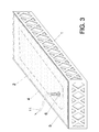
Figure 3 .- Shows a view equivalent to the previous figure wherein vacuum is applied for performing the compaction of the layer with adhesive properties by means of the incorporation of the membrane on the aerator blanket. -
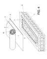
Figure 4 .- Shows the stage wherein a double sided tape overlapped with the compacted layer with adhesive properties is arranged, after removing the aerator blanket and membrane. -
Figure 5 .- Shows the stage wherein the mesh-shaped layer with conductive properties is arranged. -
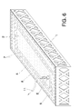
Figure 6 .- Shows the stage wherein the mesh compaction is performed. -
Figure 7 .- Shows the stage wherein the mesh compaction is carried out and the paper sheet coating it is removed. -
Figure 8 .- Shows a view wherein the cutting of the compacted mesh surplus is started. -
Figure 9 .- Shows a view wherein the complete cut of the mesh surplus, according to the double sided tape outline, has been performed. -
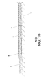
Figure 10 .- Shows a view according to section A-B of the previous figure. - Next, a description of the invention is made based on the aforementioned figures.
- Before carrying out the taping for obtaining a coating piece either manually or automatically, such as for example, can be one of the pieces constituting the coating of an aircraft, a mould release agent is applied on the
tool 1 surface. The most used mould release agents are Frekote 33, Reléase All 75, Ram 225, water-based, etc. The application of the mould release agent is carried out homogeneously, uniformly, and according to the following instructions: - when dealing with a
tool 1 without a prior mould release agent, at least three layers are applied, having to leave a drying time between them. Next, the mould release agent 30 is cured for 30 minutes at 120°C. - if the
tool 1 has been used in other occasions, curing the mould release agent is not necessary when applying a new mould release agent layer over the other one already cured and for certain mould release agents, since it can be carried out at room temperature. - Because almost all of the mould release agents excepting water-based mould release agents contain volatile and inflammable solvents in their formulation, it is convenient that the application area is ventilated and free of fire hazard.
- Once the mould release agent has been cured, the
tool 1 is rubbed with a clean cloth, until eliminating the possible roughness and the opaque appearance thereof. - Once the
tool 1 is clean, a layer withadhesive properties 2 is applied. Thelayer 2 is applied on a surface exceeding the limits of thecoating skin piece 3, which has been represented by means of a dot-and-dash imaginary line. Thus, before applying thelayer 2 the outline to be adopted by the final coating piece should be known. - This
layer 2 has the function of refilling the pores that may persist on the uncovered side of the piece and thus leaving a completely smooth surface. - In addition, for the
layer 2 to be completely adhered to thetool 1, a first compaction is carried out, wherefore anaerator blanket 4 formed by a separating film and an aerator fabric is extended along the tool. Theblanket 4 has the function of allowing the vacuum to equally circulate at all points of thetool 1, and must have dimensions larger than the compaction area, in this case the one constituted by theprevious layer 2. - Next, a membrane with
resilient properties 5 is extended on the entire surface of thetool 1, which is connected, by means of avacuum valve 6, to avacuum rubber 11 which in turn is connected to a compressor (not represented), such that next the air is extracted from the interior of themembrane 5, comprised between this and thetool 1, and thelayer 2 and theaerator blanket 4 previously mounted are compacted. In order to attain an optimum vacuum, it has to be ensured that there are no folds on themembrane 5 and no element protruding from the interior of thetool 1. - Vacuum is applied for about 10 minutes at -600 mm/Hg, in order to attain the correct compaction of the
layer 2. - Next, the
membrane 5 is rolled up in a cardboardsmall tube 12 for its subsequent storage and theaerator blanket 4 is removed by folding it and leaving it in a clean place. Next, some patterns of composite materials (not showed) are positioned, which are mounted on the areas where it is required due to mechanical and/or designing needs, such as for example, on the assembly areas with the adjacent coating pieces. - The process continues by placing a double
sided tape 7 on the entire outline of thelayer 2, overlapping therewith between 2 and 5 mm. The doublesided tape 7 must never stay within theoutline 3 constituting the coating skin piece. - Next a layer with
conductive properties 8 is mounted, for example in the form of a mesh with dimensions exceeding the doublesided tape outline 7, leaving theprotective paper 9 of themesh 8 on the face opposite to thetool 1. - The
aerator blanket 4 is extended again and the protective plastic of the doublesided tape 7 is removed in order to now extend again the membrane withresilient properties 5 by unrolling it from the cardboardsmall tube 12 and thevacuum valve 6 is connected to the compressor by means of thehose 11. Just like the previous case for attaining an optimum vacuum, it has to be ensured that there are no folds on themembrane 5 and no element is protruding from the interior of thetool 1. - The compaction is applied on the
mesh 8 for about 10 minutes at -600 mm/Hg and then themembrane 5 is rolled up again in the cardboardsmall tube 12 for its subsequent storage and theaerator blanket 4 is removed. - In the compaction process, the perfect adhesion of the
mesh 8 on the doublesided tape 7 and on thelayer 2 has been produced; such that now the surplus of themesh 8 exceeding the doublesided tape outline 7 should be cut, if appropriate. For that purpose, acut 10 on one of the ends of the surplus is carried out, always in the widest area, and leveled with the doublesided tape outline 7, which allows that if the surplus is pulled out in the same direction as the doublesided tape 7 causes that, as themesh 8 is attached and compacted to the doublesided tape 7, when the surplus is pulled out, the doublesided tape 7 itself acts as cutter leaving themesh 8 leveled with thetape 7. - Next, some sheets rigidizing certain skin areas are positioned, their situation normally matching the assembly of elements such as the piece assembling a coating piece with another one, through coupling elements, and finally said sheets are covered with a new layer with adhesive properties with similar dimensions.
- To conclude, the
aerator blanket 4 is placed again and themembrane 5 is placed again, applying the vacuum that enables the compaction of the described last layers. - When the skin is manually laminated, the
membrane 5 is rolled up, for example in a cardboard small tube and theaerator blanket 4 is removed in order to laminate by hand the layers constituting the skin laminate. Once finished, theaerator blanket 4 is extended again as well as themembrane 5, applying the vacuum that enables the compaction of the last stacked layers. Since hand skin manufacturing requires more compactions between layers, the aforementioned steps are repeated. However, if the skin laminate is stacked in an automatic machine, thetool 1 is maintained connected continuously to the vacuum network until coming into said machine, which tapes over the previously compacted layers a laminate constituting the coating skin, which will be subsequently beveled.
Claims (6)
- COMPACTION PROCESS OF A PIECE OF COMPOSITE MATERIALS, comprising:- applying a mould release agent on a coating piece manufacturing tool (1) and carrying out its curing;- applying a layer with adhesive properties (2) on the mould release agent, in order to leave a smooth surface of the piece to be obtained,
characterized in that further comprises:- extending along the layer with adhesive properties (2) an aerator blanket (4) with dimensions larger than said layer with adhesive properties (2);- extending a membrane with resilient properties (5) on the entire surface of the tool (1), avoiding leaving folds and that the blanket (4) does not protrude; and the membrane with resilient properties (5) including a vacuum valve (6) in order to extract the air comprised between the membrane with resilient properties (5) and the tool (1), and compacting the layer with adhesive properties (2) keeping the vacuum for certain time;- removing the membrane with resilient properties (5) and the aerator blanket (4). - COMPACTION PROCESS OF A PIECE OF COMPOSITE MATERIALS, according to claim 1, characterized in that, upon removing the membrane with resilient properties (5) and the aerator blanket (4), comprises:- positioning patterns of composite materials on areas where the piece to be obtained should have higher rigidity;- placing a double sided tape (7) with protective plastic on the entire outline defining the piece to be obtained and overlapping it with the layer with adhesive properties (2), but in such a way that it does not stay within the outline (3) of the piece to be obtained;- mounting a layer with conductive properties (8), selected from a pattern layer, an impregnated layer, a pre-impregnated pattern layer, and a pre-impregnated mesh-shaped layer, with one of the faces protected by a protective paper (9), which is mounted on the surface of the compacted layer with adhesive properties (2), leaving the protective paper (9) arranged on the face opposite to the tool (1), the surplus part of the layer with conductive properties (8) protruding with respect to the double sided tape (7) outline;- extending the aerator blanket (4) and removing the protective plastic of the double sided tape (7);- extending the membrane with resilient properties (5) in order to carry out next a second compaction extracting the air comprised between the membrane with resilient properties (5) and the tool (1), and adhering the layer with conductive properties (8) to the layer with adhesive properties (2), to patterns of composite materials, and to the double sided tape (7);- removing the membrane with resilient properties (5) and the aerator blanket (4), detaching the protective paper (9) from the mesh with conductive properties (8) and cutting away the surplus of the mesh with conductive properties (8) according to the double sided tape (7) outline and with the help of said double sided tape (7) outline.
- COMPACTION PROCESS OF A PIECE OF COMPOSITE MATERIALS, according to claim 1, characterized in that, comprises:- positioning some rigidizing sheets on the layer with conductive properties (8) on the areas wherein the piece to be obtained requires higher rigidity, and said rigidizing sheets being next covered with a new layer with adhesive properties with similar dimensions;- extending the aerator blanket (4) and the membrane with resilient properties (5) in order to compact again, extracting the air comprised between the membrane with resilient properties (5) and the tool (1);- carrying out a taping selected from a manual taping and a automatic taping which laminates over the previously compacted layers in order to obtain a laminated piece named coating piece skin.
- COMPACTION PROCESS OF A PIECE OF COMPOSITE MATERIALS, according to claims 1, 2 and 3, characterized in that, the stage of removing the membrane with resilient properties (5) is carried out by rolling it up in a cylindrical tubular body (12).
- COMPACTION PROCESS OF A PIECE OF COMPOSITE MATERIALS, according to claim 2, characterized in that the overlapping of the double sided tape (7) with the layer with adhesive properties (2) is carried out between 2 and 5 mm.
- COMPACTION PROCESS OF A PIECE OF COMPOSITE MATERIALS, according to claim 2, characterized in that the cutting of the layer of the mesh with conductive properties (8) is carried out according to the following stages:- making a cut (10) at the widest area of one of the surplus ends and leveled with the double sided tape (7) outline;- pulling out the cut surplus in the direction of the double sided tape (7) outline, for the cut to be carried out in the same direction that said double sided tape (7) outline, being adhered to the double sided tape (7), the mesh with conductive properties (8) being leveled with said double sided tape (7).
Applications Claiming Priority (2)
| Application Number | Priority Date | Filing Date | Title |
|---|---|---|---|
| ES200931151A ES2371623B1 (en) | 2009-12-11 | 2009-12-11 | COMPACTION PROCESS OF A COMPOSITE MATERIALS PIECE. |
| PCT/ES2010/070690 WO2011070204A1 (en) | 2009-12-11 | 2010-10-26 | Compacting process for a part made of composite materials |
Publications (3)
| Publication Number | Publication Date |
|---|---|
| EP2511079A1 true EP2511079A1 (en) | 2012-10-17 |
| EP2511079A4 EP2511079A4 (en) | 2017-11-29 |
| EP2511079B1 EP2511079B1 (en) | 2021-12-29 |
Family
ID=44145133
Family Applications (1)
| Application Number | Title | Priority Date | Filing Date |
|---|---|---|---|
| EP10835527.2A Not-in-force EP2511079B1 (en) | 2009-12-11 | 2010-10-26 | Compacting process for a part made of composite materials |
Country Status (6)
| Country | Link |
|---|---|
| US (1) | US8932427B2 (en) |
| EP (1) | EP2511079B1 (en) |
| CN (1) | CN102741040B (en) |
| ES (2) | ES2371623B1 (en) |
| RU (1) | RU2540657C2 (en) |
| WO (1) | WO2011070204A1 (en) |
Cited By (2)
| Publication number | Priority date | Publication date | Assignee | Title |
|---|---|---|---|---|
| US11654669B2 (en) | 2017-05-26 | 2023-05-23 | The Boeing Company | Flexible vacuum securement of objects to complex surfaces |
| US12030266B2 (en) | 2020-03-13 | 2024-07-09 | The Boeing Company | Scrolls that vacuum secure objects to complex surfaces |
Families Citing this family (2)
| Publication number | Priority date | Publication date | Assignee | Title |
|---|---|---|---|---|
| US11312026B2 (en) | 2019-10-10 | 2022-04-26 | The Boeing Company | Placement and compaction of objects via vacuum |
| US11904558B2 (en) | 2020-10-09 | 2024-02-20 | The Boeing Company | Placement and compaction of multiple objects via vacuum heads with floating end effectors |
Family Cites Families (21)
| Publication number | Priority date | Publication date | Assignee | Title |
|---|---|---|---|---|
| US3666600A (en) * | 1969-03-10 | 1972-05-30 | North American Rockwell | Apparatus for forming layup laminate |
| US4287015A (en) * | 1976-10-18 | 1981-09-01 | Danner Harold J Jun | Vacuum bag used in making laminated products |
| US4816106A (en) * | 1984-12-13 | 1989-03-28 | Aeritalia Saipa - Gruppo Velivoli Da Trasporto | Method for the controlled curing of composites |
| US4836765A (en) * | 1987-12-03 | 1989-06-06 | United Technologies Corporation | Molding apparatus for composite materials |
| US4851280A (en) * | 1988-04-01 | 1989-07-25 | E. I. Du Pont De Nemours And Company | Composite tooling for composites manufacture |
| US5250342A (en) * | 1989-05-24 | 1993-10-05 | United Technologies Corporation | Composite EMI shield having clean, highly conductive surfaces for conductive bonding |
| US5131834A (en) * | 1990-12-21 | 1992-07-21 | Northrop Corporation | Silicone gel isostatic pressurizing bag and method of use and manufacture |
| US5430937A (en) * | 1994-07-15 | 1995-07-11 | United Technologies Corporation | Apparatus and methods for fabricating a helicopter main rotor blade |
| FR2728395A1 (en) * | 1994-12-16 | 1996-06-21 | Eurocopter France | COMPOSITE MATERIAL ELEMENT WITH ELECTRIC CONTINUITY ASSEMBLY THROUGH THE ELEMENT, ITS MANUFACTURING METHOD AND ITS USE IN AERONAUTICS |
| CA2282387C (en) * | 1997-02-27 | 2007-10-02 | Advanced Composites Group Limited | Improvements in or relating to moulding methods and moulded articles |
| NL1007018C2 (en) * | 1997-09-11 | 1999-03-12 | Hollandse Signaalapparaten Bv | Fiber-plastic composite body for electromagnetic shielding, provided with an electrical contact strip. |
| US6851945B2 (en) * | 2002-12-11 | 2005-02-08 | Northrop Grumman Corporation | Seal-less reusable vacuum bag |
| US20050126699A1 (en) * | 2003-12-15 | 2005-06-16 | Anna Yen | Process for the manufacture of composite structures |
| DE102004030658A1 (en) * | 2004-06-24 | 2006-01-19 | Meier Vakuumtechnik Gmbh | laminator |
| US7503368B2 (en) * | 2004-11-24 | 2009-03-17 | The Boeing Company | Composite sections for aircraft fuselages and other structures, and methods and systems for manufacturing such sections |
| WO2006112823A1 (en) | 2005-04-13 | 2006-10-26 | The Boeing Company | Method to eliminate undulations in a composite panel |
| RU2285613C1 (en) * | 2005-05-18 | 2006-10-20 | Федеральное государственное унитарное предприятие "Московское машиностроительное производственное предприятие "САЛЮТ" (ФГУП "ММПП "САЛЮТ") | Method of manufacturing multilayer article from polymeric composition materials |
| DE102006050579B3 (en) * | 2006-10-26 | 2008-03-06 | Deutsches Zentrum für Luft- und Raumfahrt e.V. | Making aerospace assemblies from differing and incompatible composites, combines vacuum film impregnation, use of transition film and common thermal treatment |
| WO2008086022A1 (en) * | 2007-01-09 | 2008-07-17 | American Consulting Technology & Research Inc. | Multi-function vacuum bag for composite part manuacture |
| US8916073B2 (en) * | 2007-02-23 | 2014-12-23 | Richard W. Rydin | Method of making a natural rubber vacuum bag by spray processes, natural rubber vacuum bag made using spray process, and method for using natural rubber bag made using spray process |
| ITTO20070507A1 (en) * | 2007-07-11 | 2009-01-12 | Alenia Aeronautica Spa | PROCESS OF MANUFACTURING OF A STRUCTURE OF A MONOLITHIC WING WITH AN INTEGRAL PROFILE |
-
2009
- 2009-12-11 ES ES200931151A patent/ES2371623B1/en not_active Expired - Fee Related
-
2010
- 2010-10-26 WO PCT/ES2010/070690 patent/WO2011070204A1/en not_active Ceased
- 2010-10-26 CN CN201080063553.1A patent/CN102741040B/en not_active Expired - Fee Related
- 2010-10-26 ES ES10835527T patent/ES2908947T3/en active Active
- 2010-10-26 EP EP10835527.2A patent/EP2511079B1/en not_active Not-in-force
- 2010-10-26 RU RU2012128931/05A patent/RU2540657C2/en active
-
2012
- 2012-06-11 US US13/493,637 patent/US8932427B2/en active Active
Non-Patent Citations (1)
| Title |
|---|
| See references of WO2011070204A1 * |
Cited By (2)
| Publication number | Priority date | Publication date | Assignee | Title |
|---|---|---|---|---|
| US11654669B2 (en) | 2017-05-26 | 2023-05-23 | The Boeing Company | Flexible vacuum securement of objects to complex surfaces |
| US12030266B2 (en) | 2020-03-13 | 2024-07-09 | The Boeing Company | Scrolls that vacuum secure objects to complex surfaces |
Also Published As
| Publication number | Publication date |
|---|---|
| WO2011070204A1 (en) | 2011-06-16 |
| EP2511079B1 (en) | 2021-12-29 |
| ES2371623A1 (en) | 2012-01-05 |
| RU2540657C2 (en) | 2015-02-10 |
| ES2371623B1 (en) | 2012-11-22 |
| EP2511079A4 (en) | 2017-11-29 |
| US20130153140A1 (en) | 2013-06-20 |
| RU2012128931A (en) | 2014-01-20 |
| CN102741040A (en) | 2012-10-17 |
| CN102741040B (en) | 2014-11-26 |
| ES2908947T3 (en) | 2022-05-04 |
| US8932427B2 (en) | 2015-01-13 |
Similar Documents
| Publication | Publication Date | Title |
|---|---|---|
| US8932427B2 (en) | Compaction process of a piece of composite materials | |
| US3795559A (en) | Aircraft fluted core radome and method for making the same | |
| CN101370643B (en) | Method of making composite panels with U-shaped stiffeners | |
| DE102008044069B3 (en) | Shaped body for producing a fiber composite component | |
| EP2540482A1 (en) | Method for manufacturing composite cylindrical body, method for molding fiber-reinforced resin molded object and molded object | |
| US10100165B2 (en) | Silicone-coated release film with a special vacuum deep drawing capability | |
| US10385823B2 (en) | Composite component having safety edge | |
| US5076871A (en) | Method of forming composite prepreg articles utilizing heat-shrinkable braided sleeves | |
| KR102542348B1 (en) | Method and Apparatus for Forming Radius Filler Kits | |
| ATE262408T1 (en) | METHOD FOR PRODUCING PRE-HARDENED COMPOSITE PARTS WITH STIFFENERS APPLIED IN A FRESH CONDITION | |
| CN102905866A (en) | Method and mould for moulding a wind turbine blade | |
| US20210299920A1 (en) | Method for fabricating composite structures using combined resin film and dry fabric | |
| EP1401658A4 (en) | Method of manufacturing a hollow section, grid stiffened panel | |
| EP2894136A1 (en) | Improved method of making fire resistant sustainable aircraft interior panels | |
| CN114103158A (en) | Forming method of special-shaped composite skirt for solid rocket motor | |
| JP6335712B2 (en) | Composite material forming jig and composite material forming method | |
| JP6212544B2 (en) | Manufacturing method of fiber composite structure member | |
| CN110225816A (en) | Shaped component with peeling layer | |
| US20130056150A1 (en) | Process for applying resin on the surface of a moulding base tool, treated with mould-release substances, in order to obtain bodies of composite material |
Legal Events
| Date | Code | Title | Description |
|---|---|---|---|
| PUAI | Public reference made under article 153(3) epc to a published international application that has entered the european phase |
Free format text: ORIGINAL CODE: 0009012 |
|
| 17P | Request for examination filed |
Effective date: 20120704 |
|
| AK | Designated contracting states |
Kind code of ref document: A1 Designated state(s): AL AT BE BG CH CY CZ DE DK EE ES FI FR GB GR HR HU IE IS IT LI LT LU LV MC MK MT NL NO PL PT RO RS SE SI SK SM TR |
|
| DAX | Request for extension of the european patent (deleted) | ||
| RA4 | Supplementary search report drawn up and despatched (corrected) |
Effective date: 20171026 |
|
| RIC1 | Information provided on ipc code assigned before grant |
Ipc: B32B 37/10 20060101ALI20171020BHEP Ipc: B32B 37/02 20060101ALI20171020BHEP Ipc: B29C 70/44 20060101AFI20171020BHEP |
|
| STAA | Information on the status of an ep patent application or granted ep patent |
Free format text: STATUS: EXAMINATION IS IN PROGRESS |
|
| 17Q | First examination report despatched |
Effective date: 20201203 |
|
| GRAP | Despatch of communication of intention to grant a patent |
Free format text: ORIGINAL CODE: EPIDOSNIGR1 |
|
| STAA | Information on the status of an ep patent application or granted ep patent |
Free format text: STATUS: GRANT OF PATENT IS INTENDED |
|
| INTG | Intention to grant announced |
Effective date: 20210714 |
|
| GRAS | Grant fee paid |
Free format text: ORIGINAL CODE: EPIDOSNIGR3 |
|
| GRAA | (expected) grant |
Free format text: ORIGINAL CODE: 0009210 |
|
| STAA | Information on the status of an ep patent application or granted ep patent |
Free format text: STATUS: THE PATENT HAS BEEN GRANTED |
|
| AK | Designated contracting states |
Kind code of ref document: B1 Designated state(s): AL AT BE BG CH CY CZ DE DK EE ES FI FR GB GR HR HU IE IS IT LI LT LU LV MC MK MT NL NO PL PT RO RS SE SI SK SM TR |
|
| REG | Reference to a national code |
Ref country code: GB Ref legal event code: FG4D |
|
| REG | Reference to a national code |
Ref country code: CH Ref legal event code: EP |
|
| REG | Reference to a national code |
Ref country code: AT Ref legal event code: REF Ref document number: 1458374 Country of ref document: AT Kind code of ref document: T Effective date: 20220115 |
|
| REG | Reference to a national code |
Ref country code: IE Ref legal event code: FG4D |
|
| REG | Reference to a national code |
Ref country code: DE Ref legal event code: R096 Ref document number: 602010067951 Country of ref document: DE |
|
| REG | Reference to a national code |
Ref country code: LT Ref legal event code: MG9D |
|
| PG25 | Lapsed in a contracting state [announced via postgrant information from national office to epo] |
Ref country code: RS Free format text: LAPSE BECAUSE OF FAILURE TO SUBMIT A TRANSLATION OF THE DESCRIPTION OR TO PAY THE FEE WITHIN THE PRESCRIBED TIME-LIMIT Effective date: 20211229 Ref country code: LT Free format text: LAPSE BECAUSE OF FAILURE TO SUBMIT A TRANSLATION OF THE DESCRIPTION OR TO PAY THE FEE WITHIN THE PRESCRIBED TIME-LIMIT Effective date: 20211229 Ref country code: FI Free format text: LAPSE BECAUSE OF FAILURE TO SUBMIT A TRANSLATION OF THE DESCRIPTION OR TO PAY THE FEE WITHIN THE PRESCRIBED TIME-LIMIT Effective date: 20211229 Ref country code: BG Free format text: LAPSE BECAUSE OF FAILURE TO SUBMIT A TRANSLATION OF THE DESCRIPTION OR TO PAY THE FEE WITHIN THE PRESCRIBED TIME-LIMIT Effective date: 20220329 |
|
| REG | Reference to a national code |
Ref country code: NL Ref legal event code: MP Effective date: 20211229 Ref country code: ES Ref legal event code: FG2A Ref document number: 2908947 Country of ref document: ES Kind code of ref document: T3 Effective date: 20220504 |
|
| REG | Reference to a national code |
Ref country code: AT Ref legal event code: MK05 Ref document number: 1458374 Country of ref document: AT Kind code of ref document: T Effective date: 20211229 |
|
| PG25 | Lapsed in a contracting state [announced via postgrant information from national office to epo] |
Ref country code: SE Free format text: LAPSE BECAUSE OF FAILURE TO SUBMIT A TRANSLATION OF THE DESCRIPTION OR TO PAY THE FEE WITHIN THE PRESCRIBED TIME-LIMIT Effective date: 20211229 Ref country code: NO Free format text: LAPSE BECAUSE OF FAILURE TO SUBMIT A TRANSLATION OF THE DESCRIPTION OR TO PAY THE FEE WITHIN THE PRESCRIBED TIME-LIMIT Effective date: 20220329 Ref country code: LV Free format text: LAPSE BECAUSE OF FAILURE TO SUBMIT A TRANSLATION OF THE DESCRIPTION OR TO PAY THE FEE WITHIN THE PRESCRIBED TIME-LIMIT Effective date: 20211229 Ref country code: HR Free format text: LAPSE BECAUSE OF FAILURE TO SUBMIT A TRANSLATION OF THE DESCRIPTION OR TO PAY THE FEE WITHIN THE PRESCRIBED TIME-LIMIT Effective date: 20211229 Ref country code: GR Free format text: LAPSE BECAUSE OF FAILURE TO SUBMIT A TRANSLATION OF THE DESCRIPTION OR TO PAY THE FEE WITHIN THE PRESCRIBED TIME-LIMIT Effective date: 20220330 |
|
| PG25 | Lapsed in a contracting state [announced via postgrant information from national office to epo] |
Ref country code: NL Free format text: LAPSE BECAUSE OF FAILURE TO SUBMIT A TRANSLATION OF THE DESCRIPTION OR TO PAY THE FEE WITHIN THE PRESCRIBED TIME-LIMIT Effective date: 20211229 |
|
| PG25 | Lapsed in a contracting state [announced via postgrant information from national office to epo] |
Ref country code: SM Free format text: LAPSE BECAUSE OF FAILURE TO SUBMIT A TRANSLATION OF THE DESCRIPTION OR TO PAY THE FEE WITHIN THE PRESCRIBED TIME-LIMIT Effective date: 20211229 Ref country code: SK Free format text: LAPSE BECAUSE OF FAILURE TO SUBMIT A TRANSLATION OF THE DESCRIPTION OR TO PAY THE FEE WITHIN THE PRESCRIBED TIME-LIMIT Effective date: 20211229 Ref country code: RO Free format text: LAPSE BECAUSE OF FAILURE TO SUBMIT A TRANSLATION OF THE DESCRIPTION OR TO PAY THE FEE WITHIN THE PRESCRIBED TIME-LIMIT Effective date: 20211229 Ref country code: PT Free format text: LAPSE BECAUSE OF FAILURE TO SUBMIT A TRANSLATION OF THE DESCRIPTION OR TO PAY THE FEE WITHIN THE PRESCRIBED TIME-LIMIT Effective date: 20220429 Ref country code: EE Free format text: LAPSE BECAUSE OF FAILURE TO SUBMIT A TRANSLATION OF THE DESCRIPTION OR TO PAY THE FEE WITHIN THE PRESCRIBED TIME-LIMIT Effective date: 20211229 Ref country code: CZ Free format text: LAPSE BECAUSE OF FAILURE TO SUBMIT A TRANSLATION OF THE DESCRIPTION OR TO PAY THE FEE WITHIN THE PRESCRIBED TIME-LIMIT Effective date: 20211229 |
|
| PG25 | Lapsed in a contracting state [announced via postgrant information from national office to epo] |
Ref country code: PL Free format text: LAPSE BECAUSE OF FAILURE TO SUBMIT A TRANSLATION OF THE DESCRIPTION OR TO PAY THE FEE WITHIN THE PRESCRIBED TIME-LIMIT Effective date: 20211229 Ref country code: AT Free format text: LAPSE BECAUSE OF FAILURE TO SUBMIT A TRANSLATION OF THE DESCRIPTION OR TO PAY THE FEE WITHIN THE PRESCRIBED TIME-LIMIT Effective date: 20211229 |
|
| PG25 | Lapsed in a contracting state [announced via postgrant information from national office to epo] |
Ref country code: IS Free format text: LAPSE BECAUSE OF FAILURE TO SUBMIT A TRANSLATION OF THE DESCRIPTION OR TO PAY THE FEE WITHIN THE PRESCRIBED TIME-LIMIT Effective date: 20220429 |
|
| REG | Reference to a national code |
Ref country code: DE Ref legal event code: R097 Ref document number: 602010067951 Country of ref document: DE |
|
| PG25 | Lapsed in a contracting state [announced via postgrant information from national office to epo] |
Ref country code: DK Free format text: LAPSE BECAUSE OF FAILURE TO SUBMIT A TRANSLATION OF THE DESCRIPTION OR TO PAY THE FEE WITHIN THE PRESCRIBED TIME-LIMIT Effective date: 20211229 Ref country code: AL Free format text: LAPSE BECAUSE OF FAILURE TO SUBMIT A TRANSLATION OF THE DESCRIPTION OR TO PAY THE FEE WITHIN THE PRESCRIBED TIME-LIMIT Effective date: 20211229 |
|
| PLBE | No opposition filed within time limit |
Free format text: ORIGINAL CODE: 0009261 |
|
| STAA | Information on the status of an ep patent application or granted ep patent |
Free format text: STATUS: NO OPPOSITION FILED WITHIN TIME LIMIT |
|
| 26N | No opposition filed |
Effective date: 20220930 |
|
| PGFP | Annual fee paid to national office [announced via postgrant information from national office to epo] |
Ref country code: FR Payment date: 20221031 Year of fee payment: 13 |
|
| PGFP | Annual fee paid to national office [announced via postgrant information from national office to epo] |
Ref country code: GB Payment date: 20221020 Year of fee payment: 13 Ref country code: ES Payment date: 20221222 Year of fee payment: 13 Ref country code: DE Payment date: 20220727 Year of fee payment: 13 |
|
| PG25 | Lapsed in a contracting state [announced via postgrant information from national office to epo] |
Ref country code: SI Free format text: LAPSE BECAUSE OF FAILURE TO SUBMIT A TRANSLATION OF THE DESCRIPTION OR TO PAY THE FEE WITHIN THE PRESCRIBED TIME-LIMIT Effective date: 20211229 |
|
| PG25 | Lapsed in a contracting state [announced via postgrant information from national office to epo] |
Ref country code: MC Free format text: LAPSE BECAUSE OF FAILURE TO SUBMIT A TRANSLATION OF THE DESCRIPTION OR TO PAY THE FEE WITHIN THE PRESCRIBED TIME-LIMIT Effective date: 20211229 Ref country code: IT Free format text: LAPSE BECAUSE OF FAILURE TO SUBMIT A TRANSLATION OF THE DESCRIPTION OR TO PAY THE FEE WITHIN THE PRESCRIBED TIME-LIMIT Effective date: 20211229 |
|
| REG | Reference to a national code |
Ref country code: CH Ref legal event code: PL |
|
| REG | Reference to a national code |
Ref country code: BE Ref legal event code: MM Effective date: 20221031 |
|
| PG25 | Lapsed in a contracting state [announced via postgrant information from national office to epo] |
Ref country code: LU Free format text: LAPSE BECAUSE OF NON-PAYMENT OF DUE FEES Effective date: 20221026 |
|
| PG25 | Lapsed in a contracting state [announced via postgrant information from national office to epo] |
Ref country code: LI Free format text: LAPSE BECAUSE OF NON-PAYMENT OF DUE FEES Effective date: 20221031 Ref country code: CH Free format text: LAPSE BECAUSE OF NON-PAYMENT OF DUE FEES Effective date: 20221031 |
|
| PG25 | Lapsed in a contracting state [announced via postgrant information from national office to epo] |
Ref country code: BE Free format text: LAPSE BECAUSE OF NON-PAYMENT OF DUE FEES Effective date: 20221031 |
|
| PG25 | Lapsed in a contracting state [announced via postgrant information from national office to epo] |
Ref country code: IE Free format text: LAPSE BECAUSE OF NON-PAYMENT OF DUE FEES Effective date: 20221026 |
|
| PG25 | Lapsed in a contracting state [announced via postgrant information from national office to epo] |
Ref country code: HU Free format text: LAPSE BECAUSE OF FAILURE TO SUBMIT A TRANSLATION OF THE DESCRIPTION OR TO PAY THE FEE WITHIN THE PRESCRIBED TIME-LIMIT; INVALID AB INITIO Effective date: 20101026 |
|
| PG25 | Lapsed in a contracting state [announced via postgrant information from national office to epo] |
Ref country code: CY Free format text: LAPSE BECAUSE OF FAILURE TO SUBMIT A TRANSLATION OF THE DESCRIPTION OR TO PAY THE FEE WITHIN THE PRESCRIBED TIME-LIMIT Effective date: 20211229 |
|
| REG | Reference to a national code |
Ref country code: DE Ref legal event code: R119 Ref document number: 602010067951 Country of ref document: DE |
|
| PG25 | Lapsed in a contracting state [announced via postgrant information from national office to epo] |
Ref country code: MK Free format text: LAPSE BECAUSE OF FAILURE TO SUBMIT A TRANSLATION OF THE DESCRIPTION OR TO PAY THE FEE WITHIN THE PRESCRIBED TIME-LIMIT Effective date: 20211229 |
|
| GBPC | Gb: european patent ceased through non-payment of renewal fee |
Effective date: 20231026 |
|
| PG25 | Lapsed in a contracting state [announced via postgrant information from national office to epo] |
Ref country code: GB Free format text: LAPSE BECAUSE OF NON-PAYMENT OF DUE FEES Effective date: 20231026 |
|
| PG25 | Lapsed in a contracting state [announced via postgrant information from national office to epo] |
Ref country code: GB Free format text: LAPSE BECAUSE OF NON-PAYMENT OF DUE FEES Effective date: 20231026 Ref country code: FR Free format text: LAPSE BECAUSE OF NON-PAYMENT OF DUE FEES Effective date: 20231031 Ref country code: DE Free format text: LAPSE BECAUSE OF NON-PAYMENT OF DUE FEES Effective date: 20240501 |
|
| PG25 | Lapsed in a contracting state [announced via postgrant information from national office to epo] |
Ref country code: MT Free format text: LAPSE BECAUSE OF FAILURE TO SUBMIT A TRANSLATION OF THE DESCRIPTION OR TO PAY THE FEE WITHIN THE PRESCRIBED TIME-LIMIT Effective date: 20211229 |
|
| REG | Reference to a national code |
Ref country code: ES Ref legal event code: FD2A Effective date: 20241209 |
|
| PG25 | Lapsed in a contracting state [announced via postgrant information from national office to epo] |
Ref country code: ES Free format text: LAPSE BECAUSE OF NON-PAYMENT OF DUE FEES Effective date: 20231027 |
|
| PG25 | Lapsed in a contracting state [announced via postgrant information from national office to epo] |
Ref country code: ES Free format text: LAPSE BECAUSE OF NON-PAYMENT OF DUE FEES Effective date: 20231027 |
|
| PG25 | Lapsed in a contracting state [announced via postgrant information from national office to epo] |
Ref country code: TR Free format text: LAPSE BECAUSE OF FAILURE TO SUBMIT A TRANSLATION OF THE DESCRIPTION OR TO PAY THE FEE WITHIN THE PRESCRIBED TIME-LIMIT Effective date: 20211229 |