EP2510986A1 - Water machine with propeller - Google Patents
Water machine with propeller Download PDFInfo
- Publication number
- EP2510986A1 EP2510986A1 EP12163527A EP12163527A EP2510986A1 EP 2510986 A1 EP2510986 A1 EP 2510986A1 EP 12163527 A EP12163527 A EP 12163527A EP 12163527 A EP12163527 A EP 12163527A EP 2510986 A1 EP2510986 A1 EP 2510986A1
- Authority
- EP
- European Patent Office
- Prior art keywords
- rod
- fixed
- frame
- fixed frame
- divaricated
- Prior art date
- Legal status (The legal status is an assumption and is not a legal conclusion. Google has not performed a legal analysis and makes no representation as to the accuracy of the status listed.)
- Withdrawn
Links
Images


Classifications
-
- B—PERFORMING OPERATIONS; TRANSPORTING
- B63—SHIPS OR OTHER WATERBORNE VESSELS; RELATED EQUIPMENT
- B63H—MARINE PROPULSION OR STEERING
- B63H16/00—Marine propulsion by muscle power
- B63H16/08—Other apparatus for converting muscle power into propulsive effort
- B63H16/12—Other apparatus for converting muscle power into propulsive effort using hand levers, cranks, pedals, or the like, e.g. water cycles, boats propelled by boat-mounted pedal cycles
- B63H16/14—Other apparatus for converting muscle power into propulsive effort using hand levers, cranks, pedals, or the like, e.g. water cycles, boats propelled by boat-mounted pedal cycles for propelled drive
-
- A—HUMAN NECESSITIES
- A63—SPORTS; GAMES; AMUSEMENTS
- A63B—APPARATUS FOR PHYSICAL TRAINING, GYMNASTICS, SWIMMING, CLIMBING, OR FENCING; BALL GAMES; TRAINING EQUIPMENT
- A63B35/00—Swimming framework with driving mechanisms operated by the swimmer or by a motor
- A63B35/06—Swimming framework with driving mechanisms operated by the swimmer or by a motor with twin-bladed paddles or buoyant members
-
- A—HUMAN NECESSITIES
- A63—SPORTS; GAMES; AMUSEMENTS
- A63B—APPARATUS FOR PHYSICAL TRAINING, GYMNASTICS, SWIMMING, CLIMBING, OR FENCING; BALL GAMES; TRAINING EQUIPMENT
- A63B35/00—Swimming framework with driving mechanisms operated by the swimmer or by a motor
- A63B35/08—Swimming framework with driving mechanisms operated by the swimmer or by a motor with propeller propulsion
- A63B35/10—Swimming framework with driving mechanisms operated by the swimmer or by a motor with propeller propulsion operated by the swimmer
-
- B—PERFORMING OPERATIONS; TRANSPORTING
- B63—SHIPS OR OTHER WATERBORNE VESSELS; RELATED EQUIPMENT
- B63B—SHIPS OR OTHER WATERBORNE VESSELS; EQUIPMENT FOR SHIPPING
- B63B1/00—Hydrodynamic or hydrostatic features of hulls or of hydrofoils
- B63B1/02—Hydrodynamic or hydrostatic features of hulls or of hydrofoils deriving lift mainly from water displacement
- B63B1/10—Hydrodynamic or hydrostatic features of hulls or of hydrofoils deriving lift mainly from water displacement with multiple hulls
- B63B1/12—Hydrodynamic or hydrostatic features of hulls or of hydrofoils deriving lift mainly from water displacement with multiple hulls the hulls being interconnected rigidly
- B63B1/125—Hydrodynamic or hydrostatic features of hulls or of hydrofoils deriving lift mainly from water displacement with multiple hulls the hulls being interconnected rigidly comprising more than two hulls
-
- B—PERFORMING OPERATIONS; TRANSPORTING
- B63—SHIPS OR OTHER WATERBORNE VESSELS; RELATED EQUIPMENT
- B63B—SHIPS OR OTHER WATERBORNE VESSELS; EQUIPMENT FOR SHIPPING
- B63B34/00—Vessels specially adapted for water sports or leisure; Body-supporting devices specially adapted for water sports or leisure
- B63B34/50—Body-supporting buoyant devices, e.g. bathing boats or water cycles
-
- B—PERFORMING OPERATIONS; TRANSPORTING
- B63—SHIPS OR OTHER WATERBORNE VESSELS; RELATED EQUIPMENT
- B63B—SHIPS OR OTHER WATERBORNE VESSELS; EQUIPMENT FOR SHIPPING
- B63B7/00—Collapsible, foldable, inflatable or like vessels
- B63B7/02—Collapsible, foldable, inflatable or like vessels comprising only rigid parts
-
- B—PERFORMING OPERATIONS; TRANSPORTING
- B63—SHIPS OR OTHER WATERBORNE VESSELS; RELATED EQUIPMENT
- B63H—MARINE PROPULSION OR STEERING
- B63H16/00—Marine propulsion by muscle power
- B63H16/08—Other apparatus for converting muscle power into propulsive effort
- B63H16/20—Other apparatus for converting muscle power into propulsive effort using rotary cranking arm
-
- A—HUMAN NECESSITIES
- A63—SPORTS; GAMES; AMUSEMENTS
- A63B—APPARATUS FOR PHYSICAL TRAINING, GYMNASTICS, SWIMMING, CLIMBING, OR FENCING; BALL GAMES; TRAINING EQUIPMENT
- A63B22/00—Exercising apparatus specially adapted for conditioning the cardio-vascular system, for training agility or co-ordination of movements
- A63B22/06—Exercising apparatus specially adapted for conditioning the cardio-vascular system, for training agility or co-ordination of movements with support elements performing a rotating cycling movement, i.e. a closed path movement
- A63B22/0605—Exercising apparatus specially adapted for conditioning the cardio-vascular system, for training agility or co-ordination of movements with support elements performing a rotating cycling movement, i.e. a closed path movement performing a circular movement, e.g. ergometers
-
- A—HUMAN NECESSITIES
- A63—SPORTS; GAMES; AMUSEMENTS
- A63B—APPARATUS FOR PHYSICAL TRAINING, GYMNASTICS, SWIMMING, CLIMBING, OR FENCING; BALL GAMES; TRAINING EQUIPMENT
- A63B2225/00—Miscellaneous features of sport apparatus, devices or equipment
- A63B2225/60—Apparatus used in water
- A63B2225/605—Floating
-
- A—HUMAN NECESSITIES
- A63—SPORTS; GAMES; AMUSEMENTS
- A63B—APPARATUS FOR PHYSICAL TRAINING, GYMNASTICS, SWIMMING, CLIMBING, OR FENCING; BALL GAMES; TRAINING EQUIPMENT
- A63B35/00—Swimming framework with driving mechanisms operated by the swimmer or by a motor
- A63B35/08—Swimming framework with driving mechanisms operated by the swimmer or by a motor with propeller propulsion
- A63B35/12—Swimming framework with driving mechanisms operated by the swimmer or by a motor with propeller propulsion operated by a motor
-
- B—PERFORMING OPERATIONS; TRANSPORTING
- B63—SHIPS OR OTHER WATERBORNE VESSELS; RELATED EQUIPMENT
- B63B—SHIPS OR OTHER WATERBORNE VESSELS; EQUIPMENT FOR SHIPPING
- B63B1/00—Hydrodynamic or hydrostatic features of hulls or of hydrofoils
- B63B1/02—Hydrodynamic or hydrostatic features of hulls or of hydrofoils deriving lift mainly from water displacement
- B63B1/10—Hydrodynamic or hydrostatic features of hulls or of hydrofoils deriving lift mainly from water displacement with multiple hulls
- B63B1/12—Hydrodynamic or hydrostatic features of hulls or of hydrofoils deriving lift mainly from water displacement with multiple hulls the hulls being interconnected rigidly
- B63B1/125—Hydrodynamic or hydrostatic features of hulls or of hydrofoils deriving lift mainly from water displacement with multiple hulls the hulls being interconnected rigidly comprising more than two hulls
- B63B2001/126—Hydrodynamic or hydrostatic features of hulls or of hydrofoils deriving lift mainly from water displacement with multiple hulls the hulls being interconnected rigidly comprising more than two hulls comprising more than three hulls
-
- B—PERFORMING OPERATIONS; TRANSPORTING
- B63—SHIPS OR OTHER WATERBORNE VESSELS; RELATED EQUIPMENT
- B63H—MARINE PROPULSION OR STEERING
- B63H16/00—Marine propulsion by muscle power
- B63H16/08—Other apparatus for converting muscle power into propulsive effort
- B63H16/20—Other apparatus for converting muscle power into propulsive effort using rotary cranking arm
- B63H2016/202—Other apparatus for converting muscle power into propulsive effort using rotary cranking arm specially adapted or arranged for being actuated by the feet of the user, e.g. using bicycle-like pedals
-
- B—PERFORMING OPERATIONS; TRANSPORTING
- B63—SHIPS OR OTHER WATERBORNE VESSELS; RELATED EQUIPMENT
- B63H—MARINE PROPULSION OR STEERING
- B63H21/00—Use of propulsion power plant or units on vessels
- B63H21/175—Use of propulsion power plant or units on vessels the vessel being powered by land vehicle supported by vessel
Definitions
- the present patent application for industrial invention relates to a water machine with propeller actuated by electrical motor or pedals.
- the machine of the invention has been devised in the water rehabilitation sector and is an absolute novelty in the field of aquatic gym machines with pedals, since it can be disposed in different ways to allow the user to pedal in different positions.
- the water machine can be provided with an electrical motor adapted to drive the propeller into rotation or with pedals and transmission between propeller and pedals.
- pedaling in water is recommended for people who need a rehabilitation period, for example, after a joint surgery.
- FR 2 618 405 discloses an aquatic pedal machine comprising a rudder and a float provided on the back of the frame. Therefore, such a machine is impaired by problems related with floating, stability, comfort and handling.
- FR 796 986 discloses an aquatic pedal machine comprising a rod with basically Y-shaped structure with two divaricated arms at the ends of which two floats are connected. Such a machine is not configurable and cannot change its position.
- DE 196 22 162 discloses an aquatic pedal machine comprising a compass-like frame hinged to a fixed frame.
- DE 24 10 352 discloses an aquatic pedal machine wherein telescopic sliding of two frames is provided.
- the purpose of the present invention is a water machine with propeller that occupies a very small volume when it is not used.
- a further purpose of the present invention consists in a water machine with propeller that, in addition to achieve the aforementioned purpose, allows the user to keep his back in vertical or horizontal position during use.
- the water machine with propeller comprises a fixed frame, on the back of which a propeller is situated, and a mobile frame situated on the front of said fixed frame, which can have three positions, of which one is a non-operating compact position, and two are operating positions that allow the user to keep his back in vertical or horizontal position, respectively.
- said machine comprises a pair of rods - a front rod and a back rod - respectively fixed to the mobile frame and fixed frame, where the floats that make the machine float are fixed.
- the front rod is fixed to the mobile frame, is free to rotate with respect to a basically vertical axis and comprises a rudder.
- the water machine of the invention comprises:
- the mobile frame (5) is composed of a telescopic rod (51) inserted into an oscillating sleeve (52) hinged on the front of the fixed frame (1).
- the machine also comprises lock means (M) of said oscillating sleeve (52) that can be locked by said means (M) in either horizontal (see Fig. 2 ) or inclined position, as shown in Fig. 3 .
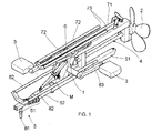
- the telescopic rod (51) can be disposed in contracted position, under the fixed frame (1), as shown in Fig. 1 , so that the machine can have a small volume.
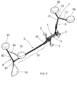
- said telescopic rod (51) can be disposed in completely extended position, as shown in Fig. 2 .
- the telescopic rod (51) in the first operating position of the machine of the invention, the telescopic rod (51) is completely extended and at the front end of said telescopic rod (51) said revolving front rod (8) is fixed, being adapted to rotate according to a vertical axis.
- Said revolving front rod (8) comprises one crosstie (84) that acts as handle for the operator who can actuate the rudder (10) while pedalling with his back in horizontal position.
- a second operating position of the machine of the invention can be obtained, wherein the machine is configured as a water bicycle, allowing the user to pedal with back in vertical position.
- said crosstie (84) acts as handle for the operator, extension of the telescopic rod (51) and the angle of inclination of the oscillating sleeve (52) supporting it.
- Figs. 4 to 8 show the machine of the invention according to a second embodiment, which differs from the first one only in the configuration of the mobile frame (50).
- the other parts of the machine, according to the second embodiment, are identical to the ones of the first embodiment and are therefore indicated with the same numerals, omitting their description.
- Said mobile frame (50) is hinged to the fixed frame (1) according to a horizontal axis and is composed of a first end rod (501) and a second central rod (502) that connects said end rod (501) to the fixed frame (1); said two rods (501, 502) being mutually hinged like a compass, according to a horizontal axis.
- the mobile frame (50) is closed under the fixed frame (1), as shown in Fig. 4 , wherein the central rod (502) and the end rod (501) are closed in compass-like configuration, in overlapped position under the fixed frame (1).
- Figs. 5 and 6 show the complete extension of the mobile frame (50), with rods (501, 502) perfectly aligned with the fixed frame (1).
- Fig. 6 shows the first operating position of the machine of the invention, which allows the user to pedal with his back in horizontal position and his stomach directed downwards.
- said revolving front rod (8) is fixed, being adapted to rotate freely according to a vertical axis.
- Fig. 8 shows the second operating position of the machine according to the invention.
- the mobile frame (50) is disposed with the central rod (502) inclined upwards, whereas the end rod (501) is disposed in practically horizontal position above the fixed frame (1).
- the free end of said end rod (501) is fixed to the lower central rod (71) of the back rod (7).
- the revolving front rod (8) is fixed to the mobile frame (50) in the hinging point between the central rod (502) and the end rod (501); said revolving front rod (8) being supported by means that alllow it to rotate according to a vertical axis in order to actuate the rudder (10).
- the seat (6) can be fixed either to the lower central rod (71) of the back rod (7) or to the end rod (501) of the mobile frame (50), as shown for illustrative purposes in Fig. 8 .
- the two rods (7, 8) can be advantageously folded, so that the machine of the invention can have a small volume when not used.
- the two upper divaricated arms (72, 82) are connected to the lower central rod (71, 81) by means of a hinge that allows the upper arm (72, 82) to be in a first idle position - as shown in Fig. 1 , wherein each upper arm (72, 82) is parallel and adjacent to the lower central rod (71, 81) and in a second operating position, wherein each upper arm (72, 82) is divaricated and perpendicular to the lower central rod (71, 81).
Landscapes
- Chemical & Material Sciences (AREA)
- Engineering & Computer Science (AREA)
- Combustion & Propulsion (AREA)
- Mechanical Engineering (AREA)
- Ocean & Marine Engineering (AREA)
- Health & Medical Sciences (AREA)
- General Health & Medical Sciences (AREA)
- Physical Education & Sports Medicine (AREA)
- Physics & Mathematics (AREA)
- Fluid Mechanics (AREA)
- Rehabilitation Tools (AREA)
Abstract
Description
- The present patent application for industrial invention relates to a water machine with propeller actuated by electrical motor or pedals.
- The machine of the invention has been devised in the water rehabilitation sector and is an absolute novelty in the field of aquatic gym machines with pedals, since it can be disposed in different ways to allow the user to pedal in different positions.
- Such a machine has been devised both for sports and rehabilitation purposes.
- In view of the above, the water machine can be provided with an electrical motor adapted to drive the propeller into rotation or with pedals and transmission between propeller and pedals.
- In fact, it must be noted that pedaling in water tones up legs and glutei and optimizes the functioning of the cardiovascular system; moreover, pedaling in water is also recommended for rehabilitation purposes because, due to hydrostatyc push, the weight of the body on joints is lower, thus eliminating stress and loads that may be harmful in some subjects.
- More precisely, pedaling in water is recommended for people who need a rehabilitation period, for example, after a joint surgery.
- In these cases, physical activity in water can be an efficacious integration to traditional rehabilitation techniques.
-
FR 2 618 405 -
FR 796 986 -
DE 196 22 162 discloses an aquatic pedal machine comprising a compass-like frame hinged to a fixed frame. -
DE 24 10 352 discloses an aquatic pedal machine wherein telescopic sliding of two frames is provided. - The purpose of the present invention is a water machine with propeller that occupies a very small volume when it is not used.
- A further purpose of the present invention consists in a water machine with propeller that, in addition to achieve the aforementioned purpose, allows the user to keep his back in vertical or horizontal position during use.
- More precisely, such a need has arisen in order to provide maximum versatility of the machine of the invention, which can be used for rehabilitation purposes both by individuals who need to pedal with their back in erected position and individuals who need to pedal while lying down with their stomach facing downwards.
- The water machine with propeller, according to the invention, comprises a fixed frame, on the back of which a propeller is situated, and a mobile frame situated on the front of said fixed frame, which can have three positions, of which one is a non-operating compact position, and two are operating positions that allow the user to keep his back in vertical or horizontal position, respectively.
- Moreover, said machine comprises a pair of rods - a front rod and a back rod - respectively fixed to the mobile frame and fixed frame, where the floats that make the machine float are fixed.
- The front rod is fixed to the mobile frame, is free to rotate with respect to a basically vertical axis and comprises a rudder.
- For explanatory reasons, the description of the water machine according to the present invention continues with reference to the attached drawings, which only have illustrative, not limiting value, wherein:
-
Fig. 1 is an axonometric view of the water machine of the invention, in compact, non-operating position; -
Fig. 2 is an axonometric view of the water machine of the invention, in a first operating position; -
Fig. 3 is an axonometric view of the water machine of the invention, in a second operating position; -
Fig. 4 is an axonometric view of the water machine of the invention according to a second embodiment, in non-operating compact position; -
Fig. 5 is an axonometric view of the water machine ofFig. 4 during the passage from the non-operating position ofFig. 4 to the first operating position ofFig. 6 ; -
Fig. 6 is an axonometric view of the water machine ofFig. 4 in a first operating position; -
Fig. 7 is an axonometric view of the water machine ofFig. 4 during the passage from the first operating position ofFig. 6 to the second operating position ofFig. 8 ; -
Fig. 8 is an axonometric view of the water machine ofFig. 4 in the second operating position; - Referring to
Figs. 1 ,2 and3 , the water machine of the invention comprises: - a fixed frame (1);
- a propeller (2) situated on the back of the fixed frame (1);
- a pair of pedals (3) supported by said fixed frame (1);
- transmission means (4) between pedals (3) and propeller (2) supported by said fixed frame (1);
- a mobile frame (5) situated on the front of said fixed frame (1);
- a back rod (7) with Y-shape supported by said fixed frame (1) and comprising a lower central rod (71) and a pair of upper divaricated arms (72);
- a seat (6) fixed to said lower central rod (71);
- a revolving front rod (8) with Y-shape supported by said mobile frame (5) and comprising a lower central rod (81) and a pair of upper divaricated arms (82);
- a pair of front floats (91) removably connected at the free ends of said upper divaricated arms (82) of the revolving front rod (8);
- a pair of back floats (92) removably fixed at the free ends (73) of said upper divaricated arms (72) of the back rod (7);
- a rudder (10) fixed at the free end of the lower central rod (81) of the revolving front rod (8).
- Referring to
Figs. 1 to 3 , according to a first embodiment of the machine of the invention, the mobile frame (5) is composed of a telescopic rod (51) inserted into an oscillating sleeve (52) hinged on the front of the fixed frame (1). - The machine also comprises lock means (M) of said oscillating sleeve (52) that can be locked by said means (M) in either horizontal (see
Fig. 2 ) or inclined position, as shown inFig. 3 . - More precisely, when said oscillating sleeve (52) is disposed in horizontal position, the telescopic rod (51) can be disposed in contracted position, under the fixed frame (1), as shown in
Fig. 1 , so that the machine can have a small volume. - Alternatively, said telescopic rod (51) can be disposed in completely extended position, as shown in
Fig. 2 . - Still referring to
Fig. 2 , in the first operating position of the machine of the invention, the telescopic rod (51) is completely extended and at the front end of said telescopic rod (51) said revolving front rod (8) is fixed, being adapted to rotate according to a vertical axis. - Said revolving front rod (8) comprises one crosstie (84) that acts as handle for the operator who can actuate the rudder (10) while pedalling with his back in horizontal position.
- Especially referring to
Fig. 3 , by disposing the oscillating sleeve (52) in inclined position and extending the telescopic rod (51) only partially, a second operating position of the machine of the invention can be obtained, wherein the machine is configured as a water bicycle, allowing the user to pedal with back in vertical position. - Also in this case, said crosstie (84) acts as handle for the operator, extension of the telescopic rod (51) and the angle of inclination of the oscillating sleeve (52) supporting it.
-
Figs. 4 to 8 show the machine of the invention according to a second embodiment, which differs from the first one only in the configuration of the mobile frame (50). The other parts of the machine, according to the second embodiment, are identical to the ones of the first embodiment and are therefore indicated with the same numerals, omitting their description. - Said mobile frame (50) is hinged to the fixed frame (1) according to a horizontal axis and is composed of a first end rod (501) and a second central rod (502) that connects said end rod (501) to the fixed frame (1); said two rods (501, 502) being mutually hinged like a compass, according to a horizontal axis.
- When the machine is not used, the mobile frame (50) is closed under the fixed frame (1), as shown in
Fig. 4 , wherein the central rod (502) and the end rod (501) are closed in compass-like configuration, in overlapped position under the fixed frame (1). -
Figs. 5 and6 show the complete extension of the mobile frame (50), with rods (501, 502) perfectly aligned with the fixed frame (1). -
Fig. 6 shows the first operating position of the machine of the invention, which allows the user to pedal with his back in horizontal position and his stomach directed downwards. In such first operating position, at the front end of said mobile frame (50) said revolving front rod (8) is fixed, being adapted to rotate freely according to a vertical axis. -
Fig. 8 shows the second operating position of the machine according to the invention. - In order to assume such position, the mobile frame (50) is disposed with the central rod (502) inclined upwards, whereas the end rod (501) is disposed in practically horizontal position above the fixed frame (1).
- The free end of said end rod (501) is fixed to the lower central rod (71) of the back rod (7).
- Referring to
Fig. 8 , the revolving front rod (8) is fixed to the mobile frame (50) in the hinging point between the central rod (502) and the end rod (501); said revolving front rod (8) being supported by means that alllow it to rotate according to a vertical axis in order to actuate the rudder (10). - According to this second embodiment, the seat (6) can be fixed either to the lower central rod (71) of the back rod (7) or to the end rod (501) of the mobile frame (50), as shown for illustrative purposes in
Fig. 8 . - Referring to
Fig. 1 , the two rods (7, 8) can be advantageously folded, so that the machine of the invention can have a small volume when not used. - More precisely, the two upper divaricated arms (72, 82) are connected to the lower central rod (71, 81) by means of a hinge that allows the upper arm (72, 82) to be in a first idle position - as shown in
Fig. 1 , wherein each upper arm (72, 82) is parallel and adjacent to the lower central rod (71, 81) and in a second operating position, wherein each upper arm (72, 82) is divaricated and perpendicular to the lower central rod (71, 81).
Claims (7)
- A pedal gym machine comprising:- a fixed frame (1),- a propeller (2) situated on the back of the fixed frame (1),- a mobile frame (5) situated on the front of said fixed frame (1),- a back rod (7) supported by said fixed frame (1),- a revolving front rod (8) supported by said mobile frame (5),- floats (91, 92) connected to said back and front roads (7, 8), and- a rudder (10),
characterized in that
said back rod (7) is "Y" shaped and it comprises a lower central rod (71) and a pair of upper divaricated arms (72), wherein a pair of back floats (92) are fixed at the free ends (73) of said upper divaricated arms (72) of the back rod;
said front rod (8) is "Y" shaped and it comprises a lower central rod (81) and a pair of upper divaricated arms (82), wherein a pair of front floats (91) are fixed at the free end of said upper divaricated arms (82) of the front rod (8);
wherein each upper divaricated arm (72, 82) is connected to the lower central rod (71, 81) by means of a hinge that allows the upper arm (72, 82) to be in a first idle position wherein it is parallel and adjacent to the lower central rod (71, 81) and in a second operating position wherein it is divaricated and perpendicular to the lower central rod (71, 81);
said rudder (10) being fixed to the free end of the a lower central rod (81) of the revolving front rod (8);
said mobile frame (5) comprising a oscillating sleeve (52) hinged on the front of the fixed frame (1) and a telescopic rod (51) inserted into said sleeve; said machine also comprising lock means (M) of said oscillating sleeve (52) that can lock it in either horizontal or inclined position, so that said mobile frame (5) can have three positions:- a non-operating position, wherein the telescopic rod (51) is arranged in contracted position under the fixed frame (1),- a first operating position, wherein the telescopic rod (51) is completely extended and the front end of said telescopic rod (51) is fixed to said revolving front rod (8) that can rotate according to a vertical axis, and- a second operating position, wherein the oscillating sleeve (52) is in inclined position, the telescopic rod (51) is partially extended and the front end of said telescopic rod (51) is fixed to said revolving front rod (8) that can rotate according to a vertical axis. - A machine as claimed in claim 1, characterized in that it comprises a seat (6) fixed to said lower central rod (71) of the back rod.
- A pedal gym machine comprising:- -a fixed frame (1),- a propeller (2) situated on the back of the fixed frame (1),- a mobile frame (50) situated on the front of said fixed frame (1),- a back rod (7) supported by said fixed frame (1),- a revolving front rod (8) supported by said mobile frame (50),- floats (91, 92) connected to said back and front roads (7, 8), and- a rudder (10),
characterized in that
said back rod (7) is "Y" shaped and it comprises a lower central rod (71) and a pair of upper divaricated arms (72), wherein a pair of back floats (92) are fixed at the free ends (73) of said upper divaricated arms (72) of the back rod;
said front rod (8) is "Y" shaped and it comprises a lower central rod (81) and a pair of upper divaricated arms (82), wherein a pair of front floats (91) are fixed at the free end of said upper divaricated arms (82) of the front rod (8);
wherein each upper divaricated arm (72, 82) is connected to the lower central rod (71, 81) by means of a hinge that allows the upper arm (72, 82) to be in a first idle position wherein it is parallel and adjacent to the lower central rod (71, 81) and in a second operating position wherein it is divaricated and perpendicular to the lower central rod (71, 81);
said rudder (10) being fixed to the free end of the a lower central rod (81) of the revolving front rod (8);
said mobile frame (50) is hinged to the fixed frame (1) according to a horizontal axis and the mobile frame (50) comprises a first end rod (501) and a second central rod (502) that connects said end rod (501) to the fixed frame (1); said two rods (501, 502) being mutually hinged like a compass, according to a horizontal axis, so that said mobile frame (50) can have three positions:- a non-operating position wherein the mobile frame (50) is closed under the fixed frame (1), with the central rod (502) and the end rod (501) in overlapped adjacent position, under the fixed frame (1),- a first operating position wherein the mobile frame (50) is completely extended, with the end and central rods (501, 502) perfectly aligned with the fixed frame (1); the front end of said end rod (501) being fixed to said revolving front rod (8) that can rotate according to a vertical axis; and- a second operating position wherein the mobile frame (50) is disposed with the central rod (502) inclined upwards, whereas the end rod (501) is disposed in horizontal position above said fixed frame (1); the revolving front rod (8) being fixed to the mobile frame (50) in the hinging point between central rod and end rod and said revolving front rod (8) is supported by means that allow it to rotate according to a vertical axis. - Machine as claimed in claim 3, characterized in that the free end of said end rod (501) of the mobile frame is fixed on the lower central rod (71) of the back rod (7).
- Machine as claimed in claim 3 or 5, characterized in that it comprises a seat (6) fixed to said end rod (501) of the mobile frame.
- Machine as claimed in anyone of the preceding claims, characterized in that said revolving front rod (8) comprises at least one crosstie (84) that acts as handle for the operator who can actuate the rudder (10) while pedalling with his back in horizontal position.
- Machine as claimed in anyone of the preceding claims, characterized in that it comprises:- a pair of pedals (3) supported by said fixed frame (1), and- transmission means (4) between pedals (3) and propeller (2) supported by said fixed frame (1).
Applications Claiming Priority (1)
| Application Number | Priority Date | Filing Date | Title |
|---|---|---|---|
| ITAN20110047 | 2011-04-12 |
Publications (1)
| Publication Number | Publication Date |
|---|---|
| EP2510986A1 true EP2510986A1 (en) | 2012-10-17 |
Family
ID=44554414
Family Applications (1)
| Application Number | Title | Priority Date | Filing Date |
|---|---|---|---|
| EP12163527A Withdrawn EP2510986A1 (en) | 2011-04-12 | 2012-04-10 | Water machine with propeller |
Country Status (2)
| Country | Link |
|---|---|
| EP (1) | EP2510986A1 (en) |
| IT (1) | ITAN20120035A1 (en) |
Cited By (3)
| Publication number | Priority date | Publication date | Assignee | Title |
|---|---|---|---|---|
| FR3055810A1 (en) * | 2016-09-14 | 2018-03-16 | Christophe Tracol | AQUATIC BIKE. |
| CN114655370A (en) * | 2022-03-28 | 2022-06-24 | 深圳市信邦五金制造有限公司 | an underwater vehicle |
| EP4545395A1 (en) | 2023-10-18 | 2025-04-30 | Ennio Bomba | Aquatic device |
Citations (7)
| Publication number | Priority date | Publication date | Assignee | Title |
|---|---|---|---|---|
| FR592990A (en) * | 1924-04-30 | 1925-08-13 | Swimming apparatus | |
| US1687194A (en) * | 1927-10-31 | 1928-10-09 | James F Caldwell | Aquatic vehicle |
| FR796986A (en) | 1935-10-25 | 1936-04-18 | Swimming machine | |
| FR1025676A (en) * | 1950-10-06 | 1953-04-17 | Swimming device | |
| DE2410352A1 (en) | 1974-03-05 | 1975-04-17 | Heinrich Mueller | Towing swimming and diving appts - made from light construction materials and capable of steering outwards from two direction |
| FR2618405A1 (en) | 1987-07-21 | 1989-01-27 | Casile Albert | Individual aquatic propulsion device |
| DE19622162A1 (en) | 1996-06-01 | 1997-12-04 | Georg Leide | Water sports appliance for self propulsion in water |
-
2012
- 2012-04-05 IT IT000035A patent/ITAN20120035A1/en unknown
- 2012-04-10 EP EP12163527A patent/EP2510986A1/en not_active Withdrawn
Patent Citations (7)
| Publication number | Priority date | Publication date | Assignee | Title |
|---|---|---|---|---|
| FR592990A (en) * | 1924-04-30 | 1925-08-13 | Swimming apparatus | |
| US1687194A (en) * | 1927-10-31 | 1928-10-09 | James F Caldwell | Aquatic vehicle |
| FR796986A (en) | 1935-10-25 | 1936-04-18 | Swimming machine | |
| FR1025676A (en) * | 1950-10-06 | 1953-04-17 | Swimming device | |
| DE2410352A1 (en) | 1974-03-05 | 1975-04-17 | Heinrich Mueller | Towing swimming and diving appts - made from light construction materials and capable of steering outwards from two direction |
| FR2618405A1 (en) | 1987-07-21 | 1989-01-27 | Casile Albert | Individual aquatic propulsion device |
| DE19622162A1 (en) | 1996-06-01 | 1997-12-04 | Georg Leide | Water sports appliance for self propulsion in water |
Cited By (3)
| Publication number | Priority date | Publication date | Assignee | Title |
|---|---|---|---|---|
| FR3055810A1 (en) * | 2016-09-14 | 2018-03-16 | Christophe Tracol | AQUATIC BIKE. |
| CN114655370A (en) * | 2022-03-28 | 2022-06-24 | 深圳市信邦五金制造有限公司 | an underwater vehicle |
| EP4545395A1 (en) | 2023-10-18 | 2025-04-30 | Ennio Bomba | Aquatic device |
Also Published As
| Publication number | Publication date |
|---|---|
| ITAN20120035A1 (en) | 2012-10-13 |
Similar Documents
| Publication | Publication Date | Title |
|---|---|---|
| EP1316332A1 (en) | Rocker arm for an electric treadmill | |
| CN205494811U (en) | Foldable waist and abdomen exercise body-building device | |
| CN101203281A (en) | Foldable or collapsible elliptical | |
| US6234942B1 (en) | Compound exerciser unit | |
| EP2510986A1 (en) | Water machine with propeller | |
| US20150164730A1 (en) | Tilting inversion exerciser having actuating handle | |
| CN205494803U (en) | Foldable domestic multifunctional body bulider | |
| US6494813B2 (en) | Stepper with additional functions to strengthen the arms and the breast | |
| US7097590B2 (en) | Gym equipment, particularly for the training of movements on the high bar | |
| EP2008634A1 (en) | Back twister | |
| KR200451492Y1 (en) | Rowing fitness equipment | |
| CN206454232U (en) | Can sit, the multifunction rower used of standing | |
| CN109045583B (en) | Treadmill for body building | |
| CN210904813U (en) | Multifunctional fitness equipment | |
| KR200451925Y1 (en) | Rowing fitness equipment | |
| CN109011386A (en) | A kind of Neurology clinic adjustable type four limbs convalescence device | |
| CN201012251Y (en) | Multifunctional oval machine | |
| KR102524057B1 (en) | A gear drive type wheel and athletic apparatus | |
| CN106618961B (en) | A kind of comprehensive body-building machine people | |
| CN205164024U (en) | Take connecting rod to turn round waist machine of marking time | |
| CN200998560Y (en) | Multifunctional Stretching Walking Machine | |
| KR200412519Y1 (en) | Lower body exercise equipment | |
| CN218420856U (en) | Walking machine | |
| CN212880772U (en) | Safe type double-person strolling machine | |
| KR200453492Y1 (en) | Outdoor chest press mechanism |
Legal Events
| Date | Code | Title | Description |
|---|---|---|---|
| PUAI | Public reference made under article 153(3) epc to a published international application that has entered the european phase |
Free format text: ORIGINAL CODE: 0009012 |
|
| AK | Designated contracting states |
Kind code of ref document: A1 Designated state(s): AL AT BE BG CH CY CZ DE DK EE ES FI FR GB GR HR HU IE IS IT LI LT LU LV MC MK MT NL NO PL PT RO RS SE SI SK SM TR |
|
| AX | Request for extension of the european patent |
Extension state: BA ME |
|
| 17P | Request for examination filed |
Effective date: 20130321 |
|
| GRAP | Despatch of communication of intention to grant a patent |
Free format text: ORIGINAL CODE: EPIDOSNIGR1 |
|
| RIC1 | Information provided on ipc code assigned before grant |
Ipc: A63B 35/06 20060101AFI20150519BHEP Ipc: A63B 35/10 20060101ALI20150519BHEP Ipc: B63B 35/74 20060101ALI20150519BHEP Ipc: B63B 7/02 20060101ALI20150519BHEP Ipc: B63B 1/12 20060101ALI20150519BHEP Ipc: B63H 16/20 20060101ALI20150519BHEP |
|
| INTG | Intention to grant announced |
Effective date: 20150617 |
|
| STAA | Information on the status of an ep patent application or granted ep patent |
Free format text: STATUS: THE APPLICATION IS DEEMED TO BE WITHDRAWN |
|
| 18D | Application deemed to be withdrawn |
Effective date: 20151028 |