EP2510972A1 - Kathetervorrichtung - Google Patents
Kathetervorrichtung Download PDFInfo
- Publication number
- EP2510972A1 EP2510972A1 EP12159235A EP12159235A EP2510972A1 EP 2510972 A1 EP2510972 A1 EP 2510972A1 EP 12159235 A EP12159235 A EP 12159235A EP 12159235 A EP12159235 A EP 12159235A EP 2510972 A1 EP2510972 A1 EP 2510972A1
- Authority
- EP
- European Patent Office
- Prior art keywords
- catheter
- branches
- rolling
- balloon
- catheter device
- Prior art date
- Legal status (The legal status is an assumption and is not a legal conclusion. Google has not performed a legal analysis and makes no representation as to the accuracy of the status listed.)
- Granted
Links
Images



Classifications
-
- A—HUMAN NECESSITIES
- A61—MEDICAL OR VETERINARY SCIENCE; HYGIENE
- A61M—DEVICES FOR INTRODUCING MEDIA INTO, OR ONTO, THE BODY; DEVICES FOR TRANSDUCING BODY MEDIA OR FOR TAKING MEDIA FROM THE BODY; DEVICES FOR PRODUCING OR ENDING SLEEP OR STUPOR
- A61M25/00—Catheters; Hollow probes
- A61M25/01—Introducing, guiding, advancing, emplacing or holding catheters
- A61M25/0105—Steering means as part of the catheter or advancing means; Markers for positioning
- A61M25/0119—Eversible catheters
-
- A—HUMAN NECESSITIES
- A61—MEDICAL OR VETERINARY SCIENCE; HYGIENE
- A61M—DEVICES FOR INTRODUCING MEDIA INTO, OR ONTO, THE BODY; DEVICES FOR TRANSDUCING BODY MEDIA OR FOR TAKING MEDIA FROM THE BODY; DEVICES FOR PRODUCING OR ENDING SLEEP OR STUPOR
- A61M25/00—Catheters; Hollow probes
- A61M25/10—Balloon catheters
- A61M25/1011—Multiple balloon catheters
-
- A—HUMAN NECESSITIES
- A61—MEDICAL OR VETERINARY SCIENCE; HYGIENE
- A61M—DEVICES FOR INTRODUCING MEDIA INTO, OR ONTO, THE BODY; DEVICES FOR TRANSDUCING BODY MEDIA OR FOR TAKING MEDIA FROM THE BODY; DEVICES FOR PRODUCING OR ENDING SLEEP OR STUPOR
- A61M25/00—Catheters; Hollow probes
- A61M25/10—Balloon catheters
- A61M25/104—Balloon catheters used for angioplasty
-
- A—HUMAN NECESSITIES
- A61—MEDICAL OR VETERINARY SCIENCE; HYGIENE
- A61M—DEVICES FOR INTRODUCING MEDIA INTO, OR ONTO, THE BODY; DEVICES FOR TRANSDUCING BODY MEDIA OR FOR TAKING MEDIA FROM THE BODY; DEVICES FOR PRODUCING OR ENDING SLEEP OR STUPOR
- A61M25/00—Catheters; Hollow probes
- A61M25/10—Balloon catheters
- A61M2025/1043—Balloon catheters with special features or adapted for special applications
- A61M2025/1045—Balloon catheters with special features or adapted for special applications for treating bifurcations, e.g. balloons in y-configuration, separate balloons or special features of the catheter for treating bifurcations
-
- A—HUMAN NECESSITIES
- A61—MEDICAL OR VETERINARY SCIENCE; HYGIENE
- A61M—DEVICES FOR INTRODUCING MEDIA INTO, OR ONTO, THE BODY; DEVICES FOR TRANSDUCING BODY MEDIA OR FOR TAKING MEDIA FROM THE BODY; DEVICES FOR PRODUCING OR ENDING SLEEP OR STUPOR
- A61M25/00—Catheters; Hollow probes
- A61M25/01—Introducing, guiding, advancing, emplacing or holding catheters
- A61M25/0105—Steering means as part of the catheter or advancing means; Markers for positioning
- A61M25/0108—Steering means as part of the catheter or advancing means; Markers for positioning using radio-opaque or ultrasound markers
Definitions
- the invention relates to a catheter device for dilating stenoses in body vessels.
- hybrid catheter Such catheters are known in great diversity since Jahrzehenten and in clinical use and have been proven in a variety of applications. A more recent stage of development are hereinafter referred to as "hybrid catheter” variants, such as those from the US 5,662,703 are known and in which the actual balloon catheter is supplemented by a so-called.
- Rolling membrane The rolling diaphragm is used in the cited document as a holding device for a tubular, radially expandable stent, and this is brought by operation of the rolling diaphragm - especially in a slightly widened state - to the site and released there.
- EP 0820259 B1 discloses such a hybrid catheter, and also its construction is adapted to the function of placing a stent in its place of use (here in the radially compressed state).
- the latter catheter device is primarily intended for use with self-expanding stents, in one embodiment it also includes a dilatation catheter.
- Fig. 1 shows a hybrid catheter 1 of the type in question in the form of a schematic longitudinal section.
- the catheter 1 has an inner shaft 3 with a first proximal port 3a for inserting a guide wire 5 and a second proximal Luer port 3b for pressurizing.
- an inflatable balloon (inner balloon) 7 is attached, which can be expanded by pressure applied to the connection 3b.
- the inner shaft 3 is surrounded over most of its length by an outer shaft 9, which at its proximal end a sealing insert 11 with low friction for sealing guidance on the outer periphery of the inner shaft 3 has.
- a rolling diaphragm 13 is mounted, which is also firmly connected, under pressure-tight separation of that, at a connection point 13a with the distal end of the inner balloon.
- the rolling diaphragm 13 similar to the inner balloon 7, by pressure, which rests against a proximal Luer connection 9a of the outer shaft 9.
- the inner shaft 3 and the outer shaft 9 have a common guide wire lumen 15 for the guide wire 5.
- the invention has for its object to provide an improved catheter device, which provides particular advantages in the expansion of stenoses in branching areas of body vessels and is easy and reliable to handle.
- the catheter device comprises two catheter branches, each having an outer and substantially distally disposed rolling membrane, in fixed association with each other (before and after traversing and dilating the stenosis).
- the fixed allocation of the two branches of the catheter at rest is realized according to a further aspect of the invention by a common catheter shaft or firmly connected catheter shafts in which both catheter branches are accommodated.
- Another aspect of the invention is that the two catheter branches have a suitable connection with each other at or near the distal end, which is maintained even with functional development and holds the two branches in a predetermined relationship to each other.
- At least one of the two catheter branches has an inner balloon catheter part; this is preferably true for both catheter branches.
- the two catheter branches have different functional dimensions, in particular a different useful diameter of the respective rolling diaphragm and / or an inner balloon of the respective balloon catheter part.
- An expedient embodiment of the latter embodiment is characterized by the fact that the two catheter branches are designed to be confusion-proof, which is realized in particular by guide-wire lumens with different diameters. This configuration makes the handling of the proposed catheter device easier and safer.
- the two catheter branches are connected together in a portion of the circumference at the distal end of their outer shafts 7a.
- the connection can be made by welding, gluing the outer shafts 7a or by a shared outer shaft 7a. This results in a certain stabilization of the overall device and, moreover, in the sense of the above-mentioned maintenance of a predetermined spatial association between the catheter branches, also acts immediately before or during the execution of their function.
- means are provided for axially fixing the position of the inner balloon 7 of the or each balloon catheter part with respect to the longitudinal axis of the catheter device.
- These are, in particular, an undercut in the respective distal outer shaft of a catheter branch, which allows the inner balloon in the outer shaft to easily unfold during dilatation and thus to become "wedged".
- the inner shaft can still be locked axially at the proximal end by means of a pinch seal (eg of the Tuhoy Borst type). This feature is particularly important as it allows flexible adaptation of the balloon lengths.
- the two catheter branches are independently adjustable in their length. Also, the position of the two branches of the catheter in the artery is independently adjustable. These two adjustment options make it possible to treat only the stenosis in the branching areas.
- an active substance coating is provided on the circumference of the two catheter branches on their rolling membrane sections.
- the blood flow is stopped first, before the active ingredient is released. This reduces the loss of active ingredient, whereby the drug can be dosed lower.
- An active substance coating is able to effect an intensive transfer of active substance into the stenosis and thus a strong therapeutic effect of a suitable active ingredient, in particular because of the relatively high pressure forces of the rolling membrane on stenotic vessel sections.
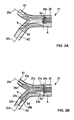
- Fig. 2A to 2D illustrate the operation of a catheter device 21 according to an embodiment of the invention in various operating conditions.
- Fig. 2A to 2D illustrate the operation of a catheter device 21 according to an embodiment of the invention in various operating conditions.
- the distal end of the catheter device is shown.
- Their further construction results for the person skilled in the art, taking into account the structure of the hybrid catheter 1 Fig. 1 , of the For the execution of the invention in particular substantially “doubled” is. Comparable parts or sections are with Fig. 1 designated reference numerals.
- Fig. 2A 11 shows a first operating state in which the catheter device 21 is advanced with its distal end - marked by an X-ray marker 28a as the distal end of a common catheter shaft 28 - to the proximal end Sp of a stenosis S in the branching region of an artery A.
- a first and second guide wire 25a, 25b are already advanced into respectively one of the branches A1 and A2 of the artery A.
- the guidewires 25a and 25b have different diameters, for example, about 0.014 "and 0.018".
- the determination of the appropriate position of the distal end of the outer shaft of the catheter device 21 for the subsequent steps is carried out by X-ray inspection using the X-ray marker 28a.
- the guide wire is adhered to the inner roller diaphragm in the inflated state of the ballon and thus is advanced as it passes through the stenosis. If there is a risk of perforation distal to the stenosis through the guidewire, then the rolling membrane must be deflated briefly to pull back the guidewire.
- Fig. 2B shows an operating state after rolling both branches A1 and A2 of the stenotic artery A, in which the common catheter shaft 28, which at the proximal End Sp of the stenosis is positioned, the distal ends of a first catheter branch 21a and a second catheter branch 21b along the respective guide wire 25a and 25b are extended into the arterial branches A1 and A2, respectively.
- Both catheter branches 21a, 21b have at the distal end in each case a rolling diaphragm 23a or 23b, and these are in the Fig. 2B shown operating state already inflated and rolled out.
- the two branches of the stenosis can be rolled simultaneously or one after the other.
- the atraumatic rolling of the stenotic area is stopped at the distal end Sd of the stenosis S in the corresponding branch by the operator by locking the inner balloon catheter at its proximal end by a clamping device.
- the length of the two catheter branches is independently adjustable.
- the catheter branches 21a, 21b each have an internal balloon (inner balloon) 27a or 27b. These are in the state shown here still in the unexpanded initial state.
- the two catheter branches 21a, 21b differ in terms of their functionally essential dimensions (hereinafter also referred to as functional dimensions), wherein Fig. 2B it can be seen that the diameter of the rolling membrane 23b placed in the further branch of the artery A2 is greater than that of the rolling membrane 23a on the other branch of the catheter 21a, which is advanced into the narrower branch A1 of the arteries.
- the unmistakable introduction of the catheter branch with the "correct" functional dimensions in the corresponding branch of the artery is ensured by the fact that the guide wire lumens of the two catheter branches have such different diameters that the larger diameter guide wire 25b only extends into the catheter branch 21b with the guide wire lumen Diameter advances and thus dictates its position. This then also results in the correct path of the guide wire 25a with the smaller diameter and thus also of the catheter branch 21a with the smaller functional dimensions.
- each catheter branch 21a / b has an X-ray marker 26a or 26b (which is only in FIG Fig. 2B is shown).
- the corresponding catheter branch 21a / b has rolled through the stenotic area, it is then further unrolled by locking on the proximal end of the common catheter shaft 28 prevented.
- the rolling membrane must be deflated before inflating the inner balloon.
- Fig. 2C shows, in the thus predetermined and held position of the catheter branches of the respective stenotic area is opened by expansion of the balloons 27a, 27b with their force. Unintentional axial lengthening of the balloons 27a, 27b along the respective catheter branch longitudinal axis by displacement of the inner shaft can be prevented, for example, by locking by means of Tuhoy Borst sealing of the catheter branch stems on the proximal catheter outlet.
- the inner balloon as in Fig. 3 for one of the catheter branches as a modified embodiment 21a ', at the distal end of the catheter shaft 28' by an undercut 28b 'in the outer shaft "anchor", since the dilation forces at maximum pressure are usually so large that the proximal locking is insufficient.
- the inner shaft is loaded on train and the outer shaft on pressure, and these react accordingly with an extension of the inner shaft and shortening of the outer shaft, so that the dilatable balloon length would be extended without countermeasure, which in turn is not desirable.
- the small counter-balloon 27a1 'forming in the undercut 28b' ensures an axial balance of the forces on the inner balloon and thus stabilizes its position.
- Fig. 2D shows an expanded state of the stenosis, ie a desired therapy result.
- the balloons 27a, 27b of the two catheter branches 21a, 21b are deflated, the connected dilation pump (not shown) is unlocked and the rolling membranes 23a, 23b are rolled back into the common catheter shaft 28 under slight internal pressure. Finally, the catheter device 27 and the guide wires 25a, 25b are withdrawn from the treated vessel.
Landscapes
- Health & Medical Sciences (AREA)
- Life Sciences & Earth Sciences (AREA)
- Heart & Thoracic Surgery (AREA)
- Anesthesiology (AREA)
- Biophysics (AREA)
- Pulmonology (AREA)
- Engineering & Computer Science (AREA)
- Biomedical Technology (AREA)
- Hematology (AREA)
- Animal Behavior & Ethology (AREA)
- General Health & Medical Sciences (AREA)
- Public Health (AREA)
- Veterinary Medicine (AREA)
- Child & Adolescent Psychology (AREA)
- Vascular Medicine (AREA)
- Media Introduction/Drainage Providing Device (AREA)
Abstract
Description
- Die Erfindung betrifft eine Kathetervorrichtung zur Aufweitung von Stenosen in Körpergefäßen.
- Derartige Katheter sind in großer Vielgestaltigkeit seit Jahrzehenten bekannt und im klinischen Einsatz und haben sich in mannigfachen Anwendungssituationen bewährt. Eine jüngere Entwicklungsstufe stellen im Folgenden als "Hybridkatheter" bezeichnete Varianten dar, wie sie etwa aus der
US 5,662,703 bekannt sind und bei denen der eigentliche Ballonkatheter noch um eine sog. Rollmembran ergänzt ist. Die Rollmembran dient in der erwähnten Druckschrift als Halteeinrichtung für einen röhrenförmigen, radial expandierbaren Stent, und dieser wird durch Betätigung der Rollmembran - insbesondere in etwas aufgeweitetem Zustand - an den Einsatzort gebracht und dort frei gegeben. Auch dieEP 0820259 B1 offenbart einen derartigen Hybridkatheter, und auch dessen Konstruktion ist auf die Funktion des Verbringens eines Stents an seinen Einsatzort (hier im radial zusammengedrückten) Zustand angepasst. Obgleich die letztgenannte Kathetervorrichtung primär für den Einsatz mit selbstexpandierenden Stents vorgesehen ist, weist sie in einer Ausführungsform auch einen Dilatationskatheter auf. -
Fig. 1 zeigt einen Hybridkatheter 1 der hier in Rede stehenden Art in Form einer schematischen Längsschnittdarstellung. Der Katheter 1 hat einen Innenschaft 3 mit einem ersten proximalen Anschluss 3a zum Einführen eines Führungsdrahtes 5 und einem zweiten proximalen Luer-Anschluss 3b zur Beaufschlagung mit Druck. Am distalen Ende des Innenschaftes 3 ist ein aufweitbarer Ballon (Innenballon) 7 angebracht, der durch am Anschluss 3b anliegenden Druck aufgeweitet werden kann. Der Innenschaft 3 ist über den größten Teil seiner Länge von einem Außenschaft 9 umgeben, welcher an seinem proximalen Ende einen Dichteinsatz 11 mit niedriger Reibung zur abdichtenden Führung auf dem Außenumfang des Innenschafts 3 hat. Am distalen Ende des Außenschafts 9 ist eine Rollmembran 13 angebracht, welche außerdem, unter druckdichter Abtrennung von jenem, an einer Verbindungsstelle 13a mit dem distalen Ende des Innenballons fest verbunden ist. In Funktion gesetzt wird die Rollmembran 13, ähnlich wie der Innenballon 7, durch Druck, welcher an einem proximalen Lueranschluss 9a des Außenschafts 9 anliegt. Zu erwähnen ist, dass der Innenschaft 3 und Außenschaft 9 ein gemeinsames Führungsdrahtlumen 15 für den Führungsdraht 5 aufweisen. - Auch eine jüngere unveröffentlichte US-Patentanmeldung der Anmelderin beschreibt einen neuartigen Hybridkatheter, der sich durch einen speziellen Aufbau mit einem äußeren, einem inneren und einem mittleren Schaft und einer speziellen axialen Lagebeziehung zwischen dem Ballon und der Rollmembran auszeichnet. In der letztgenannten Druckschrift wird der Einsatz eines derartigen Katheters zum Aufweiten von Stenosen (unabhängig von Einsetzen eines Stents) beschrieben.
- Der Erfindung liegt die Aufgabe zugrunde, eine verbesserte Kathetervorrichtung anzugeben, die insbesondere Vorteile bei der Aufweitung von Stenosen in Verzweigungsbereichen von Körpergefäßen erbringt und leicht und zuverlässig handhabbar ist.
- Diese Aufgabe wird durch eine Kathetervorrichtung mit den Merkmalen des Anspruchs 1 gelöst. Zweckmäßige Fortbildungen des erfindungsgemäßen Gedankens sind Gegenstand der abhängigen Ansprüche. Es wird des Weiteren ein Betriebsverfahren der Kathetervorrichtung vorgeschlagen.
- Gemäß einem wesentlichen Gedanken der Erfindung umfasst die Kathetervorrichtung zwei Katheterzweige, die jeweils eine außenliegende und im Wesentlichen distal angeordnete Rollmembran aufweisen, in fester Zuordnung zueinander (vor und nach dem Durchqueren und Dilatieren der Stenose). Die feste Zuordnung der beiden Katheterzweige im Ruhezustand wird gemäß einem weiteren Aspekt der Erfindung durch einen gemeinsamen Katheterschaft oder fest verbundene Katheterschäfte verwirklicht, in dem beide Katheterzweige untergebracht sind. Ein weiterer Aspekt der Erfindung besteht darin, dass die beiden Katheterzweige an oder nahe dem distalen Ende eine geeignete Verbindung miteinander haben, welche auch bei Funktionsentfaltung erhalten bleibt und die beiden Zweige in einer vorbestimmten Zuordnung zueinander hält.
- In einer Ausführung der Erfindung weist mindestens einer der beiden Katheterzweige einen innenliegenden Ballonkatheterteil auf; bevorzugt trifft dies für beide Katheterzweige zu.
- In einer weiteren Ausführung der Erfindung haben die beiden Katheterzweige unterschiedliche Funktionsabmessungen, insbesondere einen unterschiedlichen Nutzdurchmesser der jeweiligen Rollmembran und/oder eines Innenballons des jeweiligen Ballonkatheterteils. Eine zweckmäßige Ausgestaltung der letzteren Ausführung zeichnet sich durch verwechslungssichere Ausbildung der beiden Katheterzweige aus, die insbesondere durch Führungsdrahtlumen mit unterschiedlichem Durchmesser verwirklicht ist. Diese Ausgestaltung macht die Handhabung der vorgeschlagenen Kathetervorrichtung leichter und sicherer.
- Die beiden Katheterzweige sind in einem Abschnitt des Umfangs am distalen Ende ihrer Außenschäfte 7a miteinander verbunden. Die Verbindung kann durch Verschweißen, Verkleben der Außenschäfte 7a oder auch durch einen gemeinsam benutzten Außenschaft 7a erfolgen. Dies hat eine gewisse Stabilisierung der Gesamtvorrichtung zur Folge und wirkt im Übrigen im Sinne der weiter oben angesprochenen Aufrechterhaltung einer vorbestimmten räumlichen Zuordnung zwischen den Katheterzweigen auch unmittelbar vor bzw. während der Ausführung ihrer Funktion.
- In einer weiteren Ausführung der Erfindung sind Mittel zur axialen Lagefixierung des inneren Ballons 7 des oder jedes Ballonkatheterteils bezüglich der Längsachse der Kathetervorrichtung vorgesehen. Dies sind insbesondere ein Hinterschnitt im jeweiligen distalen Außenschaft eines Katheterastes, der es erlaubt, dass sich der Innenballon im Außenschaft beim Dilatieren leicht entfaltet und sich so "verkeilt". Alternativ oder zusätzlich kann noch der Innenschaft am proximalen Ende mittels einer Quetschdichtung (z.B. vom Typ Tuhoy Borst) axial arretiert werden. Diese Funktion ist besonders wichtig, da sie die flexible Anpassung der Ballonlängen ermöglicht.
- In einer Ausführung der Erfindung sind die zwei Katheterzweige in ihrer Länge unabhängig voneinander einstellbar. Ebenfalls ist die Position der zwei Katheterzweige in der Arterie unabhängig voneinander einstellbar. Diese beiden Einstellmöglichkeiten machen es möglich, dass nur die Stenose in den Verzweigungsbereichen behandelt wird.
- Gemäß einer weiteren Ausführung der Erfindung ist am Umfang der beiden Katheterzweige auf deren Rollmembranabschnitten eine Wirkstoffbeschichtung vorgesehen. Beim Ausrollen der Rollmembran wird zunächst der Blutstrom gestoppt, bevor der Wirkstoff freigesetzt wird. Dies verringert den Wirkstoffverlust, wodurch der Wirkstoff geringer dosiert werden kann. Eine Wirkstoffbeschichtung vermag insbesondere wegen der relativ hohen Andruckkräfte der Rollmembran an stenotische Gefäßabschnitte eine intensive Wirkstoffübertragung in die Stenose und somit einen starken therapeutischen Effekt eines geeigneten Wirkstoffes zu bewirken.
- Vorteile und Zweckmäßigkeiten der Erfindung ergeben sich im Übrigen aus der Beschreibung eines Ausführungsbeispiels anhand der Figuren. Von diesen zeigen:
- Fig. 1
- eine schematische Ansicht (vereinfachte Längsschnittdarstellung) eines Hybridkatheters,
- Fig. 2A bis 2D
- das distale Ende einer Ausführungsform der Erfindung in verschiedenen Betriebszuständen an einer Gefäßverzweigung mit stenotischen Bereichen und
- Fig. 3
- eine modifizierte Ausführung der Ballonkonstruktion einer erfindungsgemäßen Kathetervorrichtung.
-
Fig. 2A bis 2D illustrieren die Funktionsweise einer Kathetervorrichtung 21 gemäß einer Ausführungsform der Erfindung in verschiedenen Betriebszuständen. In den Figuren ist lediglich das distale Ende der Kathetervorrichtung gezeigt. Deren weiterer Aufbau ergibt sich für den Fachmann unter Beachtung des Aufbaus des Hybridkatheters 1 ausFig. 1 , der für die Ausführung der Erfindung insbesondere im Wesentlichen "gedoppelt" wird. Vergleichbare Teile bzw. Abschnitte sind mit anFig. 1 angelehnten Bezugsziffern bezeichnet. -
Fig. 2A zeigt einen ersten Betriebszustand, in dem die Kathetervorrichtung 21 mit ihrem distalen Ende - markiert durch einen Röntgenmarker 28a als distalen Abschluss eines gemeinsamen Katheterschafts 28 - bis an das proximale Ende Sp einer Stenose S im Verzweigungsbereich einer Arterie A vorgeschoben ist. Aus dem distalen Ende der Kathetervorrichtung 21 sind bereits ein erster und zweiter Führungsdraht 25a, 25b in jeweils einen der Äste A1 bzw. A2 der Arterie A vorgeschoben. Die Führungsdrähte 25a und 25b haben unterschiedlichen Durchmesser, beispielsweise ca. 0.014" und 0.018". Die Bestimmung der geeigneten Position des distalen Endes des Außenschaftes der Kathetervorrichtung 21 für die nachfolgenden Schritte erfolgt durch Röntgenkontrolle anhand des Röntgenmarkers 28a. - Die Rollenmembranen werden nun über den (jeweiligen) Lueranschluss 3b mit Druck beaufschlagt. Dieser Druck bewirkt, dass sich die Rollmembran ausrollen möchte und sorgt so für eine Zugkraft auf den Innenschaft am distalen Ende, die proportional zum Rollmembrandruck ist. Gleichzeitig wird der Innenballon weiter zusammengepresst. Das Durchqueren der Stenose wird stark erleichtert,
- da es keine Relativbewegung zwischen der Rollmembran außen und der Stenose gibt,
- da die Rollmembran außen die Rollmembran innen nur auf einer Linie berühren kann, und somit die Reibkraft innerhalb der Rollmembran minimal bleibt,
- und da der Innenballonkatheter und Draht zusätzliche Pushability liefern.
- Es muss beachtet werden, dass der Führungsdraht im inflatierten Zustand des Rollballons an der Innenrollmembran haftet und somit beim Durchqueren der Stenose vorgeschoben wird. Besteht die Gefahr eine Perforierung distal der Stenose durch den Führungsdraht, dann muss die Rollmembran kurz deflatiert werden, um den Führungsdraht zurück ziehen zu können.
-
Fig. 2B zeigt einen Betriebszustand nach dem Durchrollen beider Äste A1 und A2 der stenotischen Arterie A , in dem aus dem gemeinsamen Katheterschaft 28, der am proximalen Ende Sp der Stenose positioniert ist, die distalen Enden eines ersten Katheterzweigs 21a und eines zweiten Katheterzweigs 21b längs des jeweiligen Führungsdrahtes 25a bzw. 25b in die Arterien-Äste A1 bzw. A2 ausgefahren sind. Beide Katheterzweige 21a, 21b haben am distalen Ende jeweils eine Rollmembran 23a bzw. 23b, und diese sind in demFig. 2B gezeigten Betriebszustand bereits inflatiert und ausgerollt. Die beiden Äste der Stenose können gleichzeitig oder nacheinander durchrollt werden. Das atraumatische Durchrollen des stenotischen Bereiches wird jeweils am distalen Ende Sd der Stenose S im entsprechenden Ast durch den Bediener gestoppt, indem er den Innenballonkatheter an seinem proximalen Ende durch eine Klemmvorrichtung arretiert. Damit ist die Länge der beiden Katheterzweige unabhängig voneinander einstellbar. Neben den Rollmembranen haben die Katheterzweige 21a, 21b jeweils einen innenliegenden Ballon (Innenballon) 27a bzw. 27b. Diese sind in dem hier gezeigten Zustand noch im nicht expandierten Ausgangszustand. - Die beiden Katheterzweige 21a, 21b unterscheiden sich hinsichtlich ihrer funktionswesentlichen Dimensionen (nachstehend auch als Funktionsabmessungen bezeichnet), wobei in
Fig. 2B zu erkennen ist, dass der Durchmesser der Rollmembran 23b, die im weiteren Arterien-Ast A2 platziert ist, größer als derjenige der Rollmembran 23a am anderen Katheterzweig 21a ist, der in den engeren Arterien-Ast A1 vorgeschoben ist. Die verwechslungssichere Einführung des Katheterzweigs mit den "richtigen" Funktionsabmessungen im entsprechenden Arterien-Ast wird dadurch gewährleistet, dass auch die Führungsdrahtlumina der beiden Katheterzweige derart unterschiedlichen Durchmesser aufweisen, dass der Führungsdraht 25b mit dem größeren Durchmesser sich nur in den Katheterzweig 21b mit dem Führungsdrahtlumen größeren Durchmessers vorschieben lässt und somit dessen Position vorgibt. Hieraus ergibt sich dann auch der korrekte Weg des Führungsdrahtes 25a mit dem kleineren Durchmesser und somit auch des Katheterzweigs 21a mit den kleineren Funktionsabmessungen. - Zur korrekten Bestimmung der distalen Position der Katheterzweige weisen diese jeweils einen Röntgenmarker 26a bzw. 26b auf (der nur in
Fig. 2B gezeigt ist). Sobald der entsprechende Katheterzweig 21a/b den stenotischen Bereich durchrollt hat, wird er dann, durch Arretieren am proximalen Ende des gemeinsamen Katheterschaftes 28, am weiteren Ausrollen gehindert. Die Rollmembran muss vor dem Inflatieren des Innenballons deflatiert werden. - Wie
Fig. 2C zeigt, wird in der derart vorbestimmten und gehaltenen Position der Katheterzweige der jeweilige stenotische Bereich durch Expansion der Ballone 27a, 27b mit deren Kraft geöffnet. Ein ungewolltes axiales Verlängern der Ballone 27a, 27b längs der jeweiligen Katheterzweig-Längsachse durch Verschieben des Innenschaftes kann z.B. durch eine Arretierung mittels Tuhoy Borst Dichtung der Katheterzweig-Schäfte am proximalen Katheterausgang verhindert werden. - Zusätzlich kann sich der Innenballon, wie in
Fig. 3 für einen der Katheterzweige als modifizierte Ausführung 21a' gezeigt, am distalen Ende des Katheterschachtes 28' durch einen Hinterschnitt 28b' im Außenschaft "verankern", da die Dilatationskräfte beim Maximaldruck in der Regel so groß werden, dass die proximale Arretierung nicht ausreicht. Der Innenschaft wird auf Zug und der Außenschaft auf Druck belastet, und diese reagieren entsprechend mit einer Verlängerung des Innenschaftes und Verkürzung des Außenschaftes, so dass die dilatierbare Ballonlänge ohne Gegenmaßnahme verlängert würde, was wiederum nicht erwünscht ist. Der sich im Hinterschnitt 28b' ausformende kleine Gegenballon 27a1' sorgt für ein axiales Gleichgewicht der Kräfte auf den Innenballon und stabilisiert damit seine Lage. -
Fig. 2D zeigt einen aufgeweiteten Zustand der Stenose, also ein gewünschtes Therapieergebnis. - Zum Abschluss der Behandlung werden die Ballone 27a, 27b der beiden Katheterzweige 21a, 21b deflatiert, die angeschlossene Dilatationspumpe (nicht gezeigt) entsperrt und die Rollmembranen 23a, 23b unter leichtem Innendruck in den gemeinsamen Katheterschaft 28 zurückgerollt. Schließlich werden die Kathetervorrichtung 27 und die Führungsdrähte 25a, 25b aus dem therapierten Gefäß zurückgezogen.
- Die Ausführung der Erfindung ist nicht auf die oben beschriebenen Beispiele und hervorgehobenen Aspekte beschränkt, sondern ebenso in einer Vielzahl von Abwandlungen möglich, die im Rahmen fachgemäßen Handelns liegen.
Claims (12)
- Kathetervorrichtung zur Aufweitung von Stenosen im Verzweigungsbereich von Körpergefäßen, umfassend zwei Katheterzweige, die jeweils eine außenliegende distale Rollmembran aufweisen und am oder nahe dem distalen Ende des gemeinsamen Katheterschaftes miteinander verbunden sind, in einem gemeinsamen Katheterschaft.
- Kathetervorrichtung nach Anspruch 1, wobei mindestens einer der beiden Katheterzweige einen innenliegenden Ballonkatheterteil aufweist.
- Kathetervorrichtung nach Anspruch 2, wobei beide Katheterzweige jeweils einen innenliegenden Ballonkatheterteil aufweisen.
- Kathetervorrichtung nach einem der vorangehenden Ansprüche, wobei die beiden Katheterzweige unterschiedliche Funktionsabmessungen, insbesondere einen unterschiedlichen Nutzdurchmesser der jeweiligen Rollmembran und/oder eines Innenballons des jeweiligen Ballonkatheterteils, aufweisen.
- Kathetervorrichtung nach Anspruch 4, wobei die beiden Katheterzweige verwechslungssicher ausgebildet sind, insbesondere Führungsdrahtlumen mit unterschiedlichem Durchmesser haben.
- Kathetervorrichtung nach einem der vorangehenden Ansprüche, wobei die beiden Katheterzweige durch Verschweißen in einem Abschnitt ihres Umfangs miteinander verbunden sind.
- Kathetervorrichtung nach einem der Ansprüche 2 - 6, wobei der Ballon des oder jedes innenliegenden Ballonkatheterteils an oder nahe seinem distalen Ende einen Ballonende-Marker aufweist.
- Kathetervorrichtung nach einem der Ansprüche 2 - 7, wobei Mittel zur Lagefixierung des Innenballones des oder jedes Ballonkatheterteils auf der Längsachse, insbesondere durch mindestens einen Hinterschnitt im Außenschaft, vorgesehen sind.
- Kathetervorrichtung nach einem der Ansprüche 1 - 8, wobei die zwei Katheterzweige in ihrer Länge unabhängig voneinander einstellbar sind.
- Kathetervorrichtung nach einem der Ansprüche 1 - 9, wobei die zwei Katheterzweige in ihrer Position unabhängig voneinander einstellbar sind.
- Kathetervorrichtung nach einem der vorangehenden Ansprüche, wobei am Umfang der beiden Katheterzweige, insbesondere auf deren Rollmembranabschnitten, eine Wirkstoffbeschichtung und/oder eine Gleitmittelbeschichtung innen vorgesehen ist.
- Betriebsverfahren einer Kathetervorrichtung nach einem der vorangehenden Ansprüche, mit den Schritten:- Vorschieben des Katheterschafts zum Beginn einer Stenose im Verzweigungsbereich von Körpergefäßen,- Inflatieren der Rollmembranen,- paralleles oder sequentielles atraumatisches Durchrollen der stenotischen Bereiche in beiden Gefäßen mittels der Rollmembranen der beiden Katheterzweige,- Stoppen des Ausrollens der Rollmembranen, so dass der distale Marker des Innenballons den stenotischen Bereich des jeweiligen Körpergefäßes gerade durchquert hat,- Deflatieren beider Rollmembranen,- Füllen der Ballone der innenliegenden Ballonkatheterteile beider Katheterzweige zum Öffnen der Stenose im Verzweigungsbereich von Körpergefäßen ,- Deflatieren der Ballone der innenliegenden Ballonkatheterteile,- Inflatieren der Rollmembranen und Entsperren der Dilatationspumpe,- Zurückrollen der Rollmembranen in den Katheterschaft und- Zurückziehen des Katheterschafts.
Applications Claiming Priority (1)
| Application Number | Priority Date | Filing Date | Title |
|---|---|---|---|
| US201161475243P | 2011-04-14 | 2011-04-14 |
Publications (2)
| Publication Number | Publication Date |
|---|---|
| EP2510972A1 true EP2510972A1 (de) | 2012-10-17 |
| EP2510972B1 EP2510972B1 (de) | 2014-08-06 |
Family
ID=45887926
Family Applications (1)
| Application Number | Title | Priority Date | Filing Date |
|---|---|---|---|
| EP12159235.6A Active EP2510972B1 (de) | 2011-04-14 | 2012-03-13 | Kathetervorrichtung |
Country Status (2)
| Country | Link |
|---|---|
| US (1) | US20120265236A1 (de) |
| EP (1) | EP2510972B1 (de) |
Cited By (1)
| Publication number | Priority date | Publication date | Assignee | Title |
|---|---|---|---|---|
| WO2014173748A1 (de) * | 2013-04-22 | 2014-10-30 | Innora Gmbh | Ballonkatheter |
Families Citing this family (10)
| Publication number | Priority date | Publication date | Assignee | Title |
|---|---|---|---|---|
| AU2006300008A1 (en) | 2005-10-14 | 2007-04-19 | Applied Research Associates Nz Limited | A method of monitoring a surface feature and apparatus therefor |
| US9179844B2 (en) | 2011-11-28 | 2015-11-10 | Aranz Healthcare Limited | Handheld skin measuring or monitoring device |
| US10013527B2 (en) | 2016-05-02 | 2018-07-03 | Aranz Healthcare Limited | Automatically assessing an anatomical surface feature and securely managing information related to the same |
| US11116407B2 (en) | 2016-11-17 | 2021-09-14 | Aranz Healthcare Limited | Anatomical surface assessment methods, devices and systems |
| WO2018185560A2 (en) | 2017-04-04 | 2018-10-11 | Aranz Healthcare Limited | Anatomical surface assessment methods, devices and systems |
| CN109381779B (zh) * | 2017-08-02 | 2024-03-08 | 杭州唯强医疗科技有限公司 | 球囊导管 |
| US12039726B2 (en) | 2019-05-20 | 2024-07-16 | Aranz Healthcare Limited | Automated or partially automated anatomical surface assessment methods, devices and systems |
| WO2024052235A1 (en) * | 2022-09-07 | 2024-03-14 | Biotronik Ag | Rolling membrane catheter with inflating tube |
| EP4633709A1 (de) * | 2022-12-12 | 2025-10-22 | Biotronik AG | Optimiertes design einer rollmembran und eines katheters eines rollmembrankatheters |
| WO2024126130A1 (en) * | 2022-12-12 | 2024-06-20 | Biotronik Ag | Optimized design of rolling membrane as guide extension catheter |
Citations (6)
| Publication number | Priority date | Publication date | Assignee | Title |
|---|---|---|---|---|
| US5662703A (en) | 1995-04-14 | 1997-09-02 | Schneider (Usa) Inc. | Rolling membrane stent delivery device |
| US6039721A (en) * | 1996-07-24 | 2000-03-21 | Cordis Corporation | Method and catheter system for delivering medication with an everting balloon catheter |
| WO2005107643A1 (en) * | 2004-05-06 | 2005-11-17 | Invatec S.R.L. | A catheter for the treatment of bifurcations |
| US20090018501A1 (en) * | 2007-07-13 | 2009-01-15 | Yribarren Travis R | Drug Coated Balloon Catheter |
| US20090204083A1 (en) * | 2008-02-13 | 2009-08-13 | Medtronic Vascular, Inc. | Method and Apparatus for Treating Stenoses at Bifurcated Regions |
| US20110054438A1 (en) * | 2009-08-28 | 2011-03-03 | Webster Mark W I | Stent delivery at a bifurcation, systems and methods |
Family Cites Families (16)
| Publication number | Priority date | Publication date | Assignee | Title |
|---|---|---|---|---|
| US5720735A (en) * | 1997-02-12 | 1998-02-24 | Dorros; Gerald | Bifurcated endovascular catheter |
| US5984946A (en) * | 1998-02-27 | 1999-11-16 | Gupta; Mukesh | Diagnostic and guiding catheter |
| US6171339B1 (en) * | 1998-05-19 | 2001-01-09 | Sulzer Spine-Tech Inc. | Multi-lumen spinal implant guide and method |
| US6129738A (en) * | 1998-06-20 | 2000-10-10 | Medtronic Ave, Inc. | Method and apparatus for treating stenoses at bifurcated regions |
| US6117117A (en) * | 1998-08-24 | 2000-09-12 | Advanced Cardiovascular Systems, Inc. | Bifurcated catheter assembly |
| US6544278B1 (en) * | 1998-11-06 | 2003-04-08 | Scimed Life Systems, Inc. | Rolling membrane stent delivery system |
| JP2003525065A (ja) * | 1999-01-27 | 2003-08-26 | ボストン サイエンティフィック リミテッド | 分岐ステント送達システム |
| US6280412B1 (en) * | 1999-06-17 | 2001-08-28 | Scimed Life Systems, Inc. | Stent securement by balloon modification |
| US6702843B1 (en) * | 2000-04-12 | 2004-03-09 | Scimed Life Systems, Inc. | Stent delivery means with balloon retraction means |
| US6746466B2 (en) * | 2001-05-22 | 2004-06-08 | Scimed Life Systems, Inc. | Method and apparatus for managing multiple guidewires |
| US7153320B2 (en) * | 2001-12-13 | 2006-12-26 | Scimed Life Systems, Inc. | Hydraulic controlled retractable tip filter retrieval catheter |
| US7955370B2 (en) * | 2004-08-06 | 2011-06-07 | Boston Scientific Scimed, Inc. | Stent delivery system |
| US8932208B2 (en) * | 2005-05-26 | 2015-01-13 | Maquet Cardiovascular Llc | Apparatus and methods for performing minimally-invasive surgical procedures |
| WO2007005977A1 (en) * | 2005-07-05 | 2007-01-11 | Venkatesh Ramaiah | Single puncture antegrade-retrograde endovascular sheath |
| US7871396B2 (en) * | 2006-10-30 | 2011-01-18 | Boston Scientific Scimed, Inc. | Bifurcation catheter assembly and method |
| US20090132019A1 (en) * | 2007-11-15 | 2009-05-21 | Medtronic Vascular, Inc. | Bifurcate Stent Delivery Catheter |
-
2012
- 2012-03-13 EP EP12159235.6A patent/EP2510972B1/de active Active
- 2012-03-29 US US13/434,089 patent/US20120265236A1/en not_active Abandoned
Patent Citations (7)
| Publication number | Priority date | Publication date | Assignee | Title |
|---|---|---|---|---|
| US5662703A (en) | 1995-04-14 | 1997-09-02 | Schneider (Usa) Inc. | Rolling membrane stent delivery device |
| EP0820259B1 (de) | 1995-04-14 | 2003-02-05 | Boston Scientific Limited | Stentanbringungsvorrichtung mit rollmembran |
| US6039721A (en) * | 1996-07-24 | 2000-03-21 | Cordis Corporation | Method and catheter system for delivering medication with an everting balloon catheter |
| WO2005107643A1 (en) * | 2004-05-06 | 2005-11-17 | Invatec S.R.L. | A catheter for the treatment of bifurcations |
| US20090018501A1 (en) * | 2007-07-13 | 2009-01-15 | Yribarren Travis R | Drug Coated Balloon Catheter |
| US20090204083A1 (en) * | 2008-02-13 | 2009-08-13 | Medtronic Vascular, Inc. | Method and Apparatus for Treating Stenoses at Bifurcated Regions |
| US20110054438A1 (en) * | 2009-08-28 | 2011-03-03 | Webster Mark W I | Stent delivery at a bifurcation, systems and methods |
Cited By (2)
| Publication number | Priority date | Publication date | Assignee | Title |
|---|---|---|---|---|
| WO2014173748A1 (de) * | 2013-04-22 | 2014-10-30 | Innora Gmbh | Ballonkatheter |
| US10806908B2 (en) | 2013-04-22 | 2020-10-20 | Innora Gmbh | Balloon catheter |
Also Published As
| Publication number | Publication date |
|---|---|
| US20120265236A1 (en) | 2012-10-18 |
| EP2510972B1 (de) | 2014-08-06 |
Similar Documents
| Publication | Publication Date | Title |
|---|---|---|
| EP2510972B1 (de) | Kathetervorrichtung | |
| DE3690224C2 (de) | Gefäßplastische Koronar-Ballon-Sonde | |
| DE69921976T2 (de) | Dilations- und Stentzufuhrsystem für abgezweigte Lasionen | |
| DE69830227T2 (de) | Ballonkatheter zur reparatur abzweigender blutgefässen | |
| DE3853057T2 (de) | Entfernbare endoarterielle-Vorrichtung, bestimmt für die Reparatur von Ablösungen in arteriellen Wänden. | |
| DE60225147T2 (de) | Ballonkatheter und verfahren zu seiner stabilisierung bei der dehnung | |
| DE69921622T2 (de) | Konvertierbarer katheter mit einem kollabierbaren lumen | |
| DE69825200T2 (de) | Kathetersystem zum Anbringen eines Stent | |
| DE69730666T2 (de) | Stentanbringungssystem | |
| DE69224379T2 (de) | Perfusionskatheter mit schraubenförmigem ballon für die angioplastie | |
| DE69936223T2 (de) | Katheter für endovaskuläres behandeln von stenosen der kopfschlagader | |
| DE3783328T2 (de) | Gefaesskatheter mit zwei ballons. | |
| DE60021173T2 (de) | Bifurkationsstenteinführsystem | |
| DE60026466T2 (de) | Stenteinbringungssystem mit festem Führungsdraht | |
| EP3322387B1 (de) | Ballonkatheter | |
| DE69322224T2 (de) | Dilatationskatheter mit geringem querschnitt | |
| EP2383012B1 (de) | Kombinierter Rollmembran-Ballon-Katheter | |
| EP2446918A1 (de) | Ballonkatheter mit einem radial asymmetrisch dilatierbaren Abschnitt | |
| WO1988000071A1 (fr) | Catheter de dilatation a ballon expansible | |
| WO2011107249A1 (de) | Führungsdraht-/kathetergeführtes valvulotom | |
| EP3072463A1 (de) | Medizinisches Kit bzw. Set zur Behandlung eines krankhaft veränderten Hohlorgans | |
| DE69122102T2 (de) | Ptca-katheter mit fakultativ befestigtem kerndraht | |
| WO2017017259A1 (de) | Ballonkatheter | |
| EP3473197A1 (de) | Ballonkatheter | |
| DE60306455T2 (de) | Katheter zur behandlung von Intimaledissektion |
Legal Events
| Date | Code | Title | Description |
|---|---|---|---|
| PUAI | Public reference made under article 153(3) epc to a published international application that has entered the european phase |
Free format text: ORIGINAL CODE: 0009012 |
|
| AK | Designated contracting states |
Kind code of ref document: A1 Designated state(s): AL AT BE BG CH CY CZ DE DK EE ES FI FR GB GR HR HU IE IS IT LI LT LU LV MC MK MT NL NO PL PT RO RS SE SI SK SM TR |
|
| AX | Request for extension of the european patent |
Extension state: BA ME |
|
| 17P | Request for examination filed |
Effective date: 20130417 |
|
| GRAP | Despatch of communication of intention to grant a patent |
Free format text: ORIGINAL CODE: EPIDOSNIGR1 |
|
| RIC1 | Information provided on ipc code assigned before grant |
Ipc: A61M 25/01 20060101AFI20140304BHEP Ipc: A61M 25/10 20130101ALI20140304BHEP |
|
| INTG | Intention to grant announced |
Effective date: 20140327 |
|
| GRAS | Grant fee paid |
Free format text: ORIGINAL CODE: EPIDOSNIGR3 |
|
| GRAA | (expected) grant |
Free format text: ORIGINAL CODE: 0009210 |
|
| AK | Designated contracting states |
Kind code of ref document: B1 Designated state(s): AL AT BE BG CH CY CZ DE DK EE ES FI FR GB GR HR HU IE IS IT LI LT LU LV MC MK MT NL NO PL PT RO RS SE SI SK SM TR |
|
| REG | Reference to a national code |
Ref country code: GB Ref legal event code: FG4D Free format text: NOT ENGLISH |
|
| REG | Reference to a national code |
Ref country code: AT Ref legal event code: REF Ref document number: 680713 Country of ref document: AT Kind code of ref document: T Effective date: 20140815 Ref country code: CH Ref legal event code: EP |
|
| REG | Reference to a national code |
Ref country code: IE Ref legal event code: FG4D Free format text: LANGUAGE OF EP DOCUMENT: GERMAN |
|
| REG | Reference to a national code |
Ref country code: DE Ref legal event code: R096 Ref document number: 502012001072 Country of ref document: DE Effective date: 20140918 |
|
| REG | Reference to a national code |
Ref country code: NL Ref legal event code: T3 |
|
| REG | Reference to a national code |
Ref country code: LT Ref legal event code: MG4D |
|
| PG25 | Lapsed in a contracting state [announced via postgrant information from national office to epo] |
Ref country code: FI Free format text: LAPSE BECAUSE OF FAILURE TO SUBMIT A TRANSLATION OF THE DESCRIPTION OR TO PAY THE FEE WITHIN THE PRESCRIBED TIME-LIMIT Effective date: 20140806 Ref country code: GR Free format text: LAPSE BECAUSE OF FAILURE TO SUBMIT A TRANSLATION OF THE DESCRIPTION OR TO PAY THE FEE WITHIN THE PRESCRIBED TIME-LIMIT Effective date: 20141107 Ref country code: BG Free format text: LAPSE BECAUSE OF FAILURE TO SUBMIT A TRANSLATION OF THE DESCRIPTION OR TO PAY THE FEE WITHIN THE PRESCRIBED TIME-LIMIT Effective date: 20141106 Ref country code: ES Free format text: LAPSE BECAUSE OF FAILURE TO SUBMIT A TRANSLATION OF THE DESCRIPTION OR TO PAY THE FEE WITHIN THE PRESCRIBED TIME-LIMIT Effective date: 20140806 Ref country code: NO Free format text: LAPSE BECAUSE OF FAILURE TO SUBMIT A TRANSLATION OF THE DESCRIPTION OR TO PAY THE FEE WITHIN THE PRESCRIBED TIME-LIMIT Effective date: 20141106 Ref country code: LT Free format text: LAPSE BECAUSE OF FAILURE TO SUBMIT A TRANSLATION OF THE DESCRIPTION OR TO PAY THE FEE WITHIN THE PRESCRIBED TIME-LIMIT Effective date: 20140806 Ref country code: PT Free format text: LAPSE BECAUSE OF FAILURE TO SUBMIT A TRANSLATION OF THE DESCRIPTION OR TO PAY THE FEE WITHIN THE PRESCRIBED TIME-LIMIT Effective date: 20141209 Ref country code: SE Free format text: LAPSE BECAUSE OF FAILURE TO SUBMIT A TRANSLATION OF THE DESCRIPTION OR TO PAY THE FEE WITHIN THE PRESCRIBED TIME-LIMIT Effective date: 20140806 |
|
| PG25 | Lapsed in a contracting state [announced via postgrant information from national office to epo] |
Ref country code: IS Free format text: LAPSE BECAUSE OF FAILURE TO SUBMIT A TRANSLATION OF THE DESCRIPTION OR TO PAY THE FEE WITHIN THE PRESCRIBED TIME-LIMIT Effective date: 20141206 Ref country code: PL Free format text: LAPSE BECAUSE OF FAILURE TO SUBMIT A TRANSLATION OF THE DESCRIPTION OR TO PAY THE FEE WITHIN THE PRESCRIBED TIME-LIMIT Effective date: 20140806 Ref country code: RS Free format text: LAPSE BECAUSE OF FAILURE TO SUBMIT A TRANSLATION OF THE DESCRIPTION OR TO PAY THE FEE WITHIN THE PRESCRIBED TIME-LIMIT Effective date: 20140806 Ref country code: LV Free format text: LAPSE BECAUSE OF FAILURE TO SUBMIT A TRANSLATION OF THE DESCRIPTION OR TO PAY THE FEE WITHIN THE PRESCRIBED TIME-LIMIT Effective date: 20140806 Ref country code: HR Free format text: LAPSE BECAUSE OF FAILURE TO SUBMIT A TRANSLATION OF THE DESCRIPTION OR TO PAY THE FEE WITHIN THE PRESCRIBED TIME-LIMIT Effective date: 20140806 Ref country code: CY Free format text: LAPSE BECAUSE OF FAILURE TO SUBMIT A TRANSLATION OF THE DESCRIPTION OR TO PAY THE FEE WITHIN THE PRESCRIBED TIME-LIMIT Effective date: 20140806 |
|
| PG25 | Lapsed in a contracting state [announced via postgrant information from national office to epo] |
Ref country code: CZ Free format text: LAPSE BECAUSE OF FAILURE TO SUBMIT A TRANSLATION OF THE DESCRIPTION OR TO PAY THE FEE WITHIN THE PRESCRIBED TIME-LIMIT Effective date: 20140806 Ref country code: SK Free format text: LAPSE BECAUSE OF FAILURE TO SUBMIT A TRANSLATION OF THE DESCRIPTION OR TO PAY THE FEE WITHIN THE PRESCRIBED TIME-LIMIT Effective date: 20140806 Ref country code: EE Free format text: LAPSE BECAUSE OF FAILURE TO SUBMIT A TRANSLATION OF THE DESCRIPTION OR TO PAY THE FEE WITHIN THE PRESCRIBED TIME-LIMIT Effective date: 20140806 Ref country code: DK Free format text: LAPSE BECAUSE OF FAILURE TO SUBMIT A TRANSLATION OF THE DESCRIPTION OR TO PAY THE FEE WITHIN THE PRESCRIBED TIME-LIMIT Effective date: 20140806 Ref country code: IT Free format text: LAPSE BECAUSE OF FAILURE TO SUBMIT A TRANSLATION OF THE DESCRIPTION OR TO PAY THE FEE WITHIN THE PRESCRIBED TIME-LIMIT Effective date: 20140806 Ref country code: RO Free format text: LAPSE BECAUSE OF FAILURE TO SUBMIT A TRANSLATION OF THE DESCRIPTION OR TO PAY THE FEE WITHIN THE PRESCRIBED TIME-LIMIT Effective date: 20140806 |
|
| REG | Reference to a national code |
Ref country code: DE Ref legal event code: R097 Ref document number: 502012001072 Country of ref document: DE |
|
| PLBE | No opposition filed within time limit |
Free format text: ORIGINAL CODE: 0009261 |
|
| STAA | Information on the status of an ep patent application or granted ep patent |
Free format text: STATUS: NO OPPOSITION FILED WITHIN TIME LIMIT |
|
| REG | Reference to a national code |
Ref country code: DE Ref legal event code: R082 Ref document number: 502012001072 Country of ref document: DE Representative=s name: RANDOLL, SOEREN, DIPL.-CHEM. UNIV. DR. RER. NA, DE |
|
| 26N | No opposition filed |
Effective date: 20150507 |
|
| PG25 | Lapsed in a contracting state [announced via postgrant information from national office to epo] |
Ref country code: MC Free format text: LAPSE BECAUSE OF FAILURE TO SUBMIT A TRANSLATION OF THE DESCRIPTION OR TO PAY THE FEE WITHIN THE PRESCRIBED TIME-LIMIT Effective date: 20140806 Ref country code: LU Free format text: LAPSE BECAUSE OF FAILURE TO SUBMIT A TRANSLATION OF THE DESCRIPTION OR TO PAY THE FEE WITHIN THE PRESCRIBED TIME-LIMIT Effective date: 20150313 |
|
| PG25 | Lapsed in a contracting state [announced via postgrant information from national office to epo] |
Ref country code: SI Free format text: LAPSE BECAUSE OF FAILURE TO SUBMIT A TRANSLATION OF THE DESCRIPTION OR TO PAY THE FEE WITHIN THE PRESCRIBED TIME-LIMIT Effective date: 20140806 |
|
| REG | Reference to a national code |
Ref country code: FR Ref legal event code: ST Effective date: 20151130 |
|
| PG25 | Lapsed in a contracting state [announced via postgrant information from national office to epo] |
Ref country code: FR Free format text: LAPSE BECAUSE OF NON-PAYMENT OF DUE FEES Effective date: 20150331 |
|
| PG25 | Lapsed in a contracting state [announced via postgrant information from national office to epo] |
Ref country code: MT Free format text: LAPSE BECAUSE OF FAILURE TO SUBMIT A TRANSLATION OF THE DESCRIPTION OR TO PAY THE FEE WITHIN THE PRESCRIBED TIME-LIMIT Effective date: 20140806 |
|
| PG25 | Lapsed in a contracting state [announced via postgrant information from national office to epo] |
Ref country code: SM Free format text: LAPSE BECAUSE OF FAILURE TO SUBMIT A TRANSLATION OF THE DESCRIPTION OR TO PAY THE FEE WITHIN THE PRESCRIBED TIME-LIMIT Effective date: 20140806 Ref country code: HU Free format text: LAPSE BECAUSE OF FAILURE TO SUBMIT A TRANSLATION OF THE DESCRIPTION OR TO PAY THE FEE WITHIN THE PRESCRIBED TIME-LIMIT; INVALID AB INITIO Effective date: 20120313 |
|
| PG25 | Lapsed in a contracting state [announced via postgrant information from national office to epo] |
Ref country code: BE Free format text: LAPSE BECAUSE OF NON-PAYMENT OF DUE FEES Effective date: 20150331 |
|
| PG25 | Lapsed in a contracting state [announced via postgrant information from national office to epo] |
Ref country code: TR Free format text: LAPSE BECAUSE OF FAILURE TO SUBMIT A TRANSLATION OF THE DESCRIPTION OR TO PAY THE FEE WITHIN THE PRESCRIBED TIME-LIMIT Effective date: 20140806 |
|
| REG | Reference to a national code |
Ref country code: AT Ref legal event code: MM01 Ref document number: 680713 Country of ref document: AT Kind code of ref document: T Effective date: 20170313 |
|
| PG25 | Lapsed in a contracting state [announced via postgrant information from national office to epo] |
Ref country code: MK Free format text: LAPSE BECAUSE OF FAILURE TO SUBMIT A TRANSLATION OF THE DESCRIPTION OR TO PAY THE FEE WITHIN THE PRESCRIBED TIME-LIMIT Effective date: 20140806 |
|
| PG25 | Lapsed in a contracting state [announced via postgrant information from national office to epo] |
Ref country code: AT Free format text: LAPSE BECAUSE OF NON-PAYMENT OF DUE FEES Effective date: 20170313 |
|
| PG25 | Lapsed in a contracting state [announced via postgrant information from national office to epo] |
Ref country code: AL Free format text: LAPSE BECAUSE OF FAILURE TO SUBMIT A TRANSLATION OF THE DESCRIPTION OR TO PAY THE FEE WITHIN THE PRESCRIBED TIME-LIMIT Effective date: 20140806 |
|
| PGFP | Annual fee paid to national office [announced via postgrant information from national office to epo] |
Ref country code: NL Payment date: 20220322 Year of fee payment: 11 |
|
| P01 | Opt-out of the competence of the unified patent court (upc) registered |
Effective date: 20230607 |
|
| REG | Reference to a national code |
Ref country code: NL Ref legal event code: MM Effective date: 20230401 |
|
| PG25 | Lapsed in a contracting state [announced via postgrant information from national office to epo] |
Ref country code: NL Free format text: LAPSE BECAUSE OF NON-PAYMENT OF DUE FEES Effective date: 20230401 |
|
| REG | Reference to a national code |
Ref country code: DE Ref legal event code: R082 Ref document number: 502012001072 Country of ref document: DE Representative=s name: WSL PATENTANWAELTE PARTNERSCHAFT MBB, DE |
|
| REG | Reference to a national code |
Ref country code: CH Ref legal event code: U11 Free format text: ST27 STATUS EVENT CODE: U-0-0-U10-U11 (AS PROVIDED BY THE NATIONAL OFFICE) Effective date: 20260401 |
|
| PGFP | Annual fee paid to national office [announced via postgrant information from national office to epo] |
Ref country code: GB Payment date: 20260324 Year of fee payment: 15 |
|
| PGFP | Annual fee paid to national office [announced via postgrant information from national office to epo] |
Ref country code: IE Payment date: 20260319 Year of fee payment: 15 Ref country code: DE Payment date: 20260310 Year of fee payment: 15 |
|
| PGFP | Annual fee paid to national office [announced via postgrant information from national office to epo] |
Ref country code: CH Payment date: 20260401 Year of fee payment: 15 |