EP2510913A2 - Gas Distribution Assembly - Google Patents
Gas Distribution Assembly Download PDFInfo
- Publication number
- EP2510913A2 EP2510913A2 EP12162169A EP12162169A EP2510913A2 EP 2510913 A2 EP2510913 A2 EP 2510913A2 EP 12162169 A EP12162169 A EP 12162169A EP 12162169 A EP12162169 A EP 12162169A EP 2510913 A2 EP2510913 A2 EP 2510913A2
- Authority
- EP
- European Patent Office
- Prior art keywords
- gas
- modular
- coupled
- manifold
- gas manifold
- Prior art date
- Legal status (The legal status is an assumption and is not a legal conclusion. Google has not performed a legal analysis and makes no representation as to the accuracy of the status listed.)
- Withdrawn
Links
- 239000007789 gas Substances 0.000 claims description 374
- 238000004891 communication Methods 0.000 claims description 22
- 239000012530 fluid Substances 0.000 claims description 22
- QVGXLLKOCUKJST-UHFFFAOYSA-N atomic oxygen Chemical compound [O] QVGXLLKOCUKJST-UHFFFAOYSA-N 0.000 claims description 11
- 239000001301 oxygen Substances 0.000 claims description 11
- 229910052760 oxygen Inorganic materials 0.000 claims description 11
- 238000010168 coupling process Methods 0.000 description 8
- 230000008878 coupling Effects 0.000 description 6
- 238000005859 coupling reaction Methods 0.000 description 6
- 229940075473 medical gases Drugs 0.000 description 6
- IJGRMHOSHXDMSA-UHFFFAOYSA-N Atomic nitrogen Chemical compound N#N IJGRMHOSHXDMSA-UHFFFAOYSA-N 0.000 description 3
- 238000012423 maintenance Methods 0.000 description 3
- MYMOFIZGZYHOMD-UHFFFAOYSA-N Dioxygen Chemical compound O=O MYMOFIZGZYHOMD-UHFFFAOYSA-N 0.000 description 2
- 229910001882 dioxygen Inorganic materials 0.000 description 2
- 230000005611 electricity Effects 0.000 description 2
- 239000002184 metal Substances 0.000 description 2
- 208000027418 Wounds and injury Diseases 0.000 description 1
- 238000005219 brazing Methods 0.000 description 1
- 230000006378 damage Effects 0.000 description 1
- 229910001873 dinitrogen Inorganic materials 0.000 description 1
- 238000005516 engineering process Methods 0.000 description 1
- 208000014674 injury Diseases 0.000 description 1
- 230000013011 mating Effects 0.000 description 1
- 238000000034 method Methods 0.000 description 1
- 238000012986 modification Methods 0.000 description 1
- 230000004048 modification Effects 0.000 description 1
- 229910052757 nitrogen Inorganic materials 0.000 description 1
- 230000029058 respiratory gaseous exchange Effects 0.000 description 1
Images



Classifications
-
- A—HUMAN NECESSITIES
- A61—MEDICAL OR VETERINARY SCIENCE; HYGIENE
- A61G—TRANSPORT, PERSONAL CONVEYANCES, OR ACCOMMODATION SPECIALLY ADAPTED FOR PATIENTS OR DISABLED PERSONS; OPERATING TABLES OR CHAIRS; CHAIRS FOR DENTISTRY; FUNERAL DEVICES
- A61G12/00—Accommodation for nursing, e.g. in hospitals, not covered by groups A61G1/00 - A61G11/00, e.g. trolleys for transport of medicaments or food; Prescription lists
- A61G12/002—Supply appliances, e.g. columns for gas, fluid, electricity supply
- A61G12/005—Supply appliances, e.g. columns for gas, fluid, electricity supply mounted on the wall
-
- E—FIXED CONSTRUCTIONS
- E04—BUILDING
- E04H—BUILDINGS OR LIKE STRUCTURES FOR PARTICULAR PURPOSES; SWIMMING OR SPLASH BATHS OR POOLS; MASTS; FENCING; TENTS OR CANOPIES, IN GENERAL
- E04H3/00—Buildings or groups of buildings for public or similar purposes; Institutions, e.g. infirmaries or prisons
- E04H3/08—Hospitals, infirmaries, or the like; Schools; Prisons
Definitions
- the present disclosure is related to systems and methods for delivering medical gases in a hospital room. More specifically, the present disclosure is related to a medical gas delivery system for delivering various medical gases to a hospital room.
- Clinical care settings such as a hospital room, for example, serve a two-fold purpose of delivering healthcare services.
- the hospital room serves as an area for delivery of medical care.
- the hospital room serves as a residence for a recuperating patient.
- the hospital room must include state of the art technology accessible to the healthcare provider during the delivery of care.
- medical gases such as compressed air, oxygen, and vacuum may be delivered to the patient room.
- Pneumatic equipment may use compressed air as a source of power, oxygen may be provided to aid patients in breathing, and vacuum may be applied to help remove fluids from patients.
- the delivery of medical gases, electrical power, and data communication lines tends to be routed through the headwall area of the patient room.
- the headwall area also tends to support lighting for the patient room and healthcare equipment thereon.
- the headwall area may be crowded with wiring, electrical components and equipment useful in caring for a patient.
- hospitals may use headwall structures that have additional capacity for future uses. Hospitals also may provide redundant features so that flexibility in treating the patient may be achieved.
- Medical gases are delivered to each patient room by a centralized gas distribution system.
- the centralized gas distribution system supplies compressed air, oxygen gas, and vacuum by way of three separate conduits to a centralized gas manifold included in the headwall as described in U.S. Patent Application 2010/0095604 .
- the centralized gas manifold includes three sets of outlet ports, each set of outlet ports provides only one type of medical gas.
- the centralized gas manifold tends to include additional ports beyond the number of gas outlets included in the head wall so that future uses of the headwall and patient room may be supported by the centralized gas manifold. As a result, additional capacity and complexity is included in the centralized gas manifold that may not be used by the caregiver.
- a gas delivery assembly for a patient room in a healthcare facility includes a centralized gas distribution system, a first modular gas manifold, a first flexible line, and a first gas outlet.
- the centralized gas distribution system may include a source of a first gas, a first supply line coupled to the source of the first gas, and a first supply port coupled to the first supply line.
- the modular gas manifold may include a body, a supply connector, and a plurality of output ports.
- the body may be formed to include a space and the the supply connector may be coupled to the body and to the first supply port to admit the first gas from the source into the space.
- the plurality of output ports may be coupled to the body in fluid communication with the space.
- the first flexible line may be coupled to one of the plurality of output ports.
- the first gas outlet may be coupled to a wall included in the patient room and may be coupled to the flexible line to cause the first gas to be supplied to a caregiver upon demand.
- the wall includes a modular frame structure.
- the modular frame structure may include a plurality of columns secured together by removable fasteners and spaced apart from one another by a distance to form a gap therebetween.
- the modular frame structure may also include a plurality of panels coupled to the modular frame structure to form a surface. The panels being may be secured to the modular frame structure by removable fasteners.
- the removable fasteners securing the panels to the modular frame structure may be positioned in the gap and may be recessed from the surface of the panels.
- the gas outlet may be coupled to at least one of the panels.
- the first modular gas manifold and the supply line may lie in the gap behind the panels.
- One of the panels may be formed to include a first and a second aperture that open into the gap.
- the first aperture may be configured to receive the first gas outlet therein.
- the second aperture may be covered by a knock-out plate that is coupled to the panel.
- a second flexible line may be coupled to another of the plurality of the output ports included in the first modular gas manifold.
- a second modular gas manifold may include a body, a supply connector, and a plurality of output ports.
- the body may be formed to include a space.
- the supply connector may be coupled to the body of the second modular gas manifold and to the second flexible line.
- the supply connector may be configured to admit gas from the second flexible line into the space formed in the body of the second modular gas manifold.
- the plurality of output ports may be coupled to the body of the second modular gas manifold in fluid communication with the space formed in the body of the second modular gas manifold.
- the gas delivery assembly may further include a third flexible line coupled to one of the plurality of output ports included in the second modular gas manifold.
- the third flexible line may be coupled to a second gas outlet coupled to the wall.
- the gas is compressed air.
- the gas may be oxygen.
- the gas may be a vacuum.
- the gas may also be nitrogen.
- the centralized gas distribution system may further includes a source of a second gas, a second supply coupled to the source of the second gas, and a second supply port coupled to the second supply line.
- the gas distribution assembly may further include a second modular gas manifold that is spaced-apart from the first modular gas manifold.
- the second modular gas manifold may include a body formed to include a space, a supply connector coupled to the body and to the second supply line to admit the second gas from the source into the space, and a plurality of output ports coupled to the body in fluid communication with the space.
- the gas distribution assembly may further comprise a second gas outlet and a second flexible line.
- the second gas outlet may be coupled to the wall in spaced-apart relation to the first gas outlet.
- the second flexible line may be coupled to one of the plurality of output ports included in the second modular gas manifold and to the second gas outlet to provide the second gas to the caregiver upon demand.
- the gas distribution assembly further includes a third flexible line and a third modular gas manifold.
- the third flexible line may be coupled to another of the plurality of output ports included in the first modular gas manifold.
- the third modular gas manifold may include a body formed to include a space, a supply connector coupled to the body of the third modular gas manifold and to the third flexible line to admit the first gas from the third flexible line into the space formed in the body of the third modular gas manifold, and a plurality of output ports coupled to the body of the third modular gas manifold in fluid communication with the space formed in the body of the third modular gas manifold.
- a gas delivery assembly for a patient room in a healthcare facility including a wall comprises a gas delivery assembly for a patient room in a healthcare facility includes a centralized gas distribution system, a first modular gas manifold, a second modular gas manifold, and a pair of gas outlets.
- the centralized gas distribution system may include a source of a gas, a supply line coupled to the source, and a supply port coupled to the supply line.
- the first modular gas manifold may include a body formed to include a space, a supply connector interconnecting the body and the supply port to provide fluid communication with the space, and a pair of output ports coupled to the body.
- the second modular gas manifold may include a body formed to include a space, a supply connector interconnecting the body and one of the output ports included in the first modular gas manifold to provide fluid communication with the space of the first modular gas manifold and the space of the second modular gas manifold, and a pair of output ports coupled to the body of the second modular gas manifold.
- the pair of gas outlets may be coupled to the wall and may be coupled to the outlet ports of the second modular gas manifold in fluid communication with the space formed in the second modular gas manifold.
- the supply port of the centralized gas distribution system may be a female-socket quick-disconnect coupling.
- the supply connector of the first modular gas manifold may be a mating quick-disconnect plug.
- the gas distribution assembly may further include a wall.
- the wall may include a modular frame structure.
- the modular frame structure may include first column and second columns that extend upwardly from a floor. The first and second columns may be spaced apart from one another to define a vertical gap therebetween. The first and second modular gas manifolds may lie in the vertical gap between the first and second columns.
- the gas distribution assembly may further include a wall.
- the wall may include a modular frame structure.
- the modular frame structure may include first and second columns spaced-apart laterally from one another and first and second cross bars.
- the first cross bar may interconnect the first and second columns.
- the second cross bar may be spaced apart below the first cross bar.
- the second cross bar may interconnect the first and second columns and cooperate with the first cross bar to define a horizontal gap therebetween.
- the first and second modular gas manifolds may lie in the vertical gap between the first and second cross bars.
- the gas distribution assembly may further include a wall.
- the wall may include a modular frame structure and a panel coupled to the modular frame structure to form a surface.
- the panel may be formed to include a plurality of apertures that open into the gap.
- the pair of gas outlets may lie in two of the plurality of apertures.
- the wall may further include a knock-out panel.
- the knock-out panel may be coupled to the panel to cover one of the plurality of apertures not being filled with one of the pair of gas outlets.
- the gas distribution assembly may further include a pair of flexible lines.
- the flexible lines may interconnect the pair of gas outlets and the pair of outlet ports included in the second modular gas manifold.
- a gas delivery assembly for a patient room in a healthcare facility including a wall comprises a centralized gas delivery, a first modular gas manifold, a second modular gas manifold, and three gas outlets.
- the centralized gas distribution system may include a source of a gas, a supply line coupled to the source, and a supply port coupled to the supply line.
- the first modular gas manifold may include a body formed to include a space, a supply connector interconnecting the body and the supply port to provide fluid communication with the space, and a pair of output ports coupled to the body.
- the second modular gas manifold may include a body formed to include a space, a supply connector, and a pair of output ports coupled to the body of the second modular gas manifold.
- the supply connector may interconnect the body of the second modular gas manifold and the first modular gas manifold to provide fluid communication with the space of the first modular gas manifold and the space of the second modular gas manifold.
- the three gas outlets may be coupled to the wall and two of the three gas outlets may be coupled to the pair of output ports included in the first modular gas manifold. The remaining gas outlet may be coupled to one of the pair of output ports included in the second modular gas manifold.
- the first modular gas manifold may further include an expansion output port that is arranged to open into the space of the first modular gas manifold.
- the supply connector of the second modular gas manifold may be coupled to the expansion output port of the first modular gas manifold to cause the space in the second modular gas manifold to be in fluid communication with the space in the first modular gas manifold.
- Fig. 1 is a perspective view of a head wall included in a patient's room with a hospital bed arranged in front of the head wall;
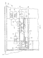
- Fig. 2 is a view similar to Fig. 1 with the hospital bed removed and portions of the head wall broken away to reveal a gas delivery assembly positioned in a gap formed in the head wall;
- Fig. 3 is a partial perspective view of another embodiment of a head wall with portions broken away to reveal another embodiment of a gas delivery assembly
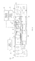
- Fig. 4 is an elevation view and diagrammatic view of another embodiment of a gas delivery assembly
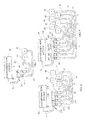
- Figs. 5 and 6 are a series of views showing how an exemplary gas delivery assembly may be expanded and modified
- Fig. 5 is an elevation view and diagrammatic view of yet another embodiment of a gas delivery assembly including three gas manifolds;
- Fig. 6 is a view similar to Fig. 5 showing the gas delivery assembly of Fig. 5 after two additional gas manifolds have been added;
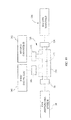
- Fig. 7 is an elevation view of a two-port gas manifold in use
- Fig. 8 is an elevation view of a four-port gas manifold in use.
- Fig. 9 is an elevation view of a six-port gas manifold in use.
- a gas delivery assembly 10 for use in a patient room in a healthcare facility is provided in a wall 12 of patient room as suggested in Fig. 1 and shown in Fig. 2 .
- the head wall 14 is configured to route electricity, compressed air, oxygen, and vacuum from the wall 12 to an outer surface 16 of the head wall 14 for use by a caregiver.
- a hospital bed 18 is positioned with a head end 19 of the hospital bed 18 adjacent to the head wall 14 so that medical equipment and tools used to treat the patient may be connected to the electrical and gas distribution systems included in the head wall 14.
- the gas delivery assembly 10 comprises a centralized gas distribution system 20, a modular gas manifold 21, a flexible line 31, and a gas outlet 41 as shown in Fig. 2 .
- the centralized gas distribution system 20 is arranged to run throughout the healthcare facility to provide medical gases to each patient room in the hospital.
- the modular gas manifold 21 is positioned to lie in a vertical gap 26 formed in the head wall 14 and is coupled to the gas distribution system 20.
- the flexible line 31 interconnects the modular gas manifold 21 to the gas outlet 41 so that a caregiver may use the medical gas provided by the gas distribution system 20.
- the gas distribution system 20 includes a first source 81 of a first gas, a first supply line 61, and a first supply port 71.
- the first source 81 of the first gas is positioned to lie outside of the head wall 14.
- the first supply line 61 is coupled to the first source 81 to provide the first gas to the patient's room.
- the first supply line 61 terminates in the gap 26 at a first supply port 71.
- the first modular gas manifold 21 is coupled to the first supply port 71 so that the first gas may be distributed as desired in the head wall 14.
- the first modular gas manifold 21 illustratively includes a body 28 formed to include a space 30 therein, a supply connector 50, and a plurality of output ports 211, 212 as shown in Figs. 2-7 .
- the supply connector 50 interconnects the body 28 and the first supply port 71 to provide fluid communication of the first gas from the first source 81 into the space 30.
- the plurality of output ports 211, 212 are coupled to the space 30 formed in the body 28 to provide the first gas when a flexible line is coupled to one of the output ports 211,212.
- the first flexible line 31 includes a first end 75, an opposite second end 76, and a flexible conduit 78 as shown in Fig. 2 .
- the first end 75 of the first flexible line 31 is coupled to the first output port 211 of the first modular gas manifold 21.
- the flexible conduit 78 is then routed through the gap 26 to the first gas outlet 41 where there second end 76 is coupled to the first gas outlet 41.
- the flexible line 31 permits technicians and maintenance personal the ability to route flexible line 31 in an initial routing path and then change flexible line 31 to different routing path.
- the head wall 14 includes a modular frame 55 and a plurality of panels 500-516 that cooperate to define an outer surface 16 as shown in Figs. 1 and 2 .
- the modular frame 55 includes a plurality of columns 581-585 secured together by removable fasteners.
- the columns 581-585 are spaced apart from one another by a distance form the gap 26 therebetween.
- the panels 501-516 are coupled to the columns 581-585 to form the outer surface 16 by additional removable fasteners that are position in the gap 26 and recessed from the surface 16 of the panels 500-516.
- the first gas outlet 41 is coupled to the second panel 502.
- a series of electrical power outlets 58 are coupled to the third panel 503 and coupled electrically to an electrical junction box 60 arranged in gap 26 as shown in Fig. 2 .
- the third panel 503 is formed to include five apertures 65, 66, 67, 68, 69 arranged to open into the gap 26.
- first gas outlet 41 is arranged to extend through aperture 65.
- a knock-out plate 70 is coupled to the outer surface 16 and arranged to cover the unused aperture.
- apertures 66 and 69 are not used, and as a result, they are shown in phantom.
- the gas distribution system 20 further includes a second source 82 of a second gas, a second supply line 62, and a second supply port 72.
- the second source 82 of the second gas is positioned to lie outside of the head wall 14.
- the second supply line 62 is coupled to the second source 82 to provide the second gas to the patient's room.
- the second supply line 62 terminates in the gap 26 at a second supply port 72 as shown in Fig. 2 .
- the gas distribution system 20 also includes a third source 83 of a third gas, a third supply line 63, and a third supply port 73.
- the third source 83 of the third gas is positioned to lie outside of the head wall 14.
- the third supply line 63 is coupled to the third source 83 to provide the third gas to the patient's room.
- the third supply line 63 terminates in the gap 26 at a third supply port 73 as shown in Fig. 2 .
- the first gas is compressed air
- the second gas is oxygen gas
- the third gas is a vacuum
- An illustrative first source 81 of compressed air may be an air compressor or a compressed-air storage tank.
- An illustrative second source 82 of oxygen may be pressurized oxygen tanks.
- An illustrative third source 83 of vacuum may be vacuum pump.
- the sources 81, 82, 83 may be located in a centralized area in the hospital away from the patient rooms so as to maximize ease of maintenance and minimize disruptions to the patients from noisy compressors and pumps.
- nitrogen gas may be used in addition to the three gases listed as needed by the hospital.
- the first gas outlet 41 is illustratively an outlet for compressed air which includes a pressure regulator that may be set by the caregiver at the appropriate pressure needed for medical equipment and accessories.
- the gas outlet may also be configured for use with the vacuum source 83 and include a vacuum canister and a regulator.
- the gas outlet may be configured for use as an oxygen outlet which may include a flow regulator so that an appropriate amount of oxygen is supplied to the patient.
- the gas delivery assembly 10 further includes a second modular gas manifold 22 and a second flexible line 32 as shown in Fig. 2 .
- the second modular gas manifold 22 includes a body 28 that is formed to include a space 30, a supply connector 50, and a plurality of output ports 221, 222.
- the supply connector 50 is arranged to interconnect the second supply port 72 and the space 30 of the second modular gas manifold 22.
- the output ports 221, 222 are coupled to the body 28 in fluid communication with the space 30.
- the second flexible line 32 is coupled to the first output port 221 and to a second gas outlet 42 as shown in Fig. 2 .
- the second gas outlet 42 is spaced-apart from first gas outlet 41.
- the gas delivery assembly 10 further includes a third modular gas manifold 23 and a third flexible line 33 as shown in Fig. 2 .
- the third modular gas manifold 23 includes a body 28 that is formed to include a space 30, a supply connector 50, and a plurality of output ports 231, 232.
- the supply connector 50 is arranged to interconnect the third supply port 73 and the space 30 of the third modular gas manifold 23.
- the output ports 231, 232 are coupled to the body 28 in fluid communication with the space 30.
- the third flexible line 33 is coupled to the first output port 231 and to a third gas outlet 43 as shown in Fig. 2 .
- the third gas outlet 43 is spaced-apart from and below the first and second gas outlets 41, 42.
- a gas delivery assembly 210 for use in a patient room in a healthcare facility is provided in a head wall 214 of patient room as suggested in Fig. 3 .
- the head wall 214 is configured to route electricity, compressed air, oxygen, and vacuum from the wall 12 to a front surface 216 of the head wall 214 for use by a caregiver.
- the gas delivery assembly 210 comprises the centralized gas distribution system 20, the modular gas manifolds 21, 23, and 23, the flexible lines 31, 32, and 33, and the gas outlets 41, 42, 43 as shown in Fig. 3 .
- the gas delivery assembly 210 is different than the gas delivery assembly 10 in that the gas delivery assembly 210 is arranged to lie in a horizontal gap 226 formed in the head wall 214 between two cross bars 94, 95 as shown in Figs. 3 and 4 .
- the gas delivery assembly 210 further includes a fourth, fifth, and sixth flexible lines 34, 35, 36 and fourth, fifth, and sixth gas outlets 44, 45, and 46.
- Fourth flexible line 34 is arranged to interconnect the second output port 212 of first modular gas manifold 21 and the fifth gas outlet 45 which is spaced apart from first gas outlet 41 on the opposite side of the head wall 214.
- Fifth flexible line 35 is arranged to interconnect the second outlet port 222 of the second modular gas manifold 22 and the sixth gas outlet 46 which is spaced apart from second gas outlet 42.
- Sixth flexible line 36 is arranged to interconnect the second output port 232 of the third modular gas manifold 23 and the fourth gas outlet 44 which is spaced apart from the third gas outlet 43.
- FIG. 4 still yet another embodiment of a gas delivery assembly 310 is shown in Fig. 4 .
- the gas delivery assembly 310 is different from the gas delivery assembly 210 in that the modular gas manifolds 21, 22, 23 are coupled to a gas distribution system 320 using a set of flexible supply hoses 91, 92, and 93 rather than coupling directly the modular gas manifolds 21, 22, 23 to their associated supply ports 71, 72, 73 included in the gas distribution systems 20 and 220.
- first, second, and third modular gas manifolds 21, 22, 23 are two-port manifolds which means that each modular gas manifold 21, 22, 23 includes two outlet ports.
- all of the outlet ports included in each modular gas manifold 21, 22, 23 are full and no further expansion is possible as configured in Figs. 3 and 4 .
- FIG. 5 Another example of a gas delivery assembly 410 is shown in an initial configuration in Fig. 5 and a changed gas delivery assembly 510 is shown in Fig. 6 .
- the initial configuration of gas delivery assembly 410 shown in Fig. 5 provides one gas outlet 41, 42, 43 for each modular gas manifold 21, 22, 23.
- This arrangement permits a user in the field to add an additional gas outlet 44, 45, 46 for each modular gas manifold 21, 22, 23 thus filling each of the available outlet ports on each modular gas manifold 21, 22, 23.
- the changed gas delivery assembly 410 has been achieved by adding a fourth and a fifth manifold 24, 25 to the gap 226 as shown in Fig. 6 .
- the fourth and fifth modular gas manifolds 24, 25 are substantially similar to the modular gas manifolds 21, 22, and 23 except that the fourth and fifth manifolds each contain four outlet ports.
- the gas delivery assembly 410 of Fig. 5 has been altered by adding fourth flexible line 34 which interconnects the second output port 212 of the first modular gas manifold 21 and a fourth gas outlet 44 which is positioned in spaced-apart relation below the first gas outlet 41.
- the gas delivery assembly 410 is further altered by adding a fifth flexible line 35 which interconnects the second outlet port 222 of the second modular gas manifold 22 and the supply connector 50 of the fourth modular gas manifold 24. This arrangement allows the second gas to flow from the second modular gas manifold 22 into a space 230 formed in a body 228 of the fourth modular gas manifold 24.
- fourth modular gas manifold 24 including four output ports 241, 242, 243, and 244, four additional gas outlets may be connected and used.
- two additional flexible lines 37, 38 are added to provide fifth and sixth gas outlets 45, 46 with the second gas.
- a sixth flexible line 36 is also added to the gas delivery assembly 310 which interconnects the second output port 232 of the third modular gas manifold 23 and the supply connector 50 of the fifth manifold 25.
- This arrangement allows third gas to flow from the third modular gas manifold 23 into the space 230 formed in the body 228 of the fifth manifold so that four output ports 251, 252, 253, 254 included in the fifth manifold may be supplied with the third gas.
- three additional flexible lines 39, 311, and 312 are added and used to interconnect seventh, eighth, and ninth gas outlets 47, 48, and 49 with the associated output ports 251, 252, and 253 included in the fifth manifold 25 as shown in Fig. 6 .
- the gas delivery assembly 410 is now arranged so that the first and fourth gas outlets 41, 44 are supplied with the first gas. Similarly, the second, fifth, and sixth gas outlets 42, 45, 46 are supplied by the second gas. Finally, the third, seventh, eighth, and ninth gas outlets 43, 47, 48, and 49 are supplied by the third gas.
- Use of the flexible lines 31, 32, 33, 34, 35, 36, 37, 38, 39, 311, and 312 and modular gas manifold 21, 22, 23, 24, and 25 allow positioning of the manifolds and routing of the supply lines to be accomplished while working in a confined gap 226 with other existing components.
- first, second, and third modular gas manifolds 21, 22, 23 is shown as a two outlet-port manifold 121 in Fig. 7 .
- the two outlet-port manifold 121 includes two output ports 211 and 222 which are shown illustratively coupled via flexible lines 31, 32 to first and second gas outlets 41, 42, and 43.
- An example of fourth and fifth modular gas manifolds 24 and 25 is shown as a four outlet-port manifold 124 in Fig. 8 .
- the four outlet-port manifold 124 includes four output ports 241, 242, 243, and 244 which are shown illustratively coupled via flexible lines 31, 32, 33, and 34 to first, second, third, and fourth gas outlets 41, 42, 43, and 44.
- a larger six outlet-port manifold 126 is shown in Fig. 8 .
- the eight outlet-port manifold 126 includes six outlet ports 261, 262, 263, 264, 265, and 266 which are coupled via six flexible lines 31, 32, 33, 34, 35, and 36 to first, second, third, fourth, fifth, and sixth 41, 42, 43, 44, 45, 46.
- Each manifold, whether a two-output manifold, a four outlet-port manifold, a six outlet-port manifold or larger each includes a number of D.I.S.S. check valves that equal the number of outlet ports included in the manifold.
- the modular gas manifold 128 includes a body 130 formed to include a space 132, the supply connector 50, a plurality of output ports 141, 142, and an expansion output port 134 as shown in Fig. 10 .
- the supply connector 50 interconnects the body 130 to the supply port included in the gas distribution system 20 so that gas is provided to the space 132.
- the plurality of output ports 141, 142 are coupled to the space 132 formed in the body 130 to provide the gas when a flexible line is coupled to one of the output ports 211, 212.
- the expansion output port 134 is used to allow expansion of modular gas manifold 128 by coupling a second modular gas manifold 136 to the expansion output port 134 of the modular gas manifold 128 as suggested in Fig. 10 .
- a port plug is coupled to the expansion output port 134 to block the flow of the gas from the space 132 through the expansion output port 134.
- the first modular gas manifold 128 may be coupled to gas distribution system 20 via supply connector 50.
- First and second outlet ports 141, 142 are coupled to the first and second gas outlets 41, 42 using all the available outlet capacity of the first modular gas manifold 128. Additional gas outlets may be supplied by adding the second modular gas manifold 136 to the expansion output port 134 of the first modular gas manifold 128.
- the supply connector 50 of the second modular gas manifold 136 may be coupled directly the expansion output port 134 of the first modular gas manifold or coupled by an intermediary flexible hose.
- the supply lines included in the gas distribution system may be metal.
- the supply ports used to terminate the supply lines may be metal and may be coupled to the supply lines by brazing the supply port onto the supply line.
- Another alternative for coupling the supply port to the supply line may be using a threaded supply line and a threaded supply port coupled to the supply line.
- Still yet another alterative for coupling the supply port to the supply line is using quick-disconnect hose couplings.
- the supply may be fitted with a female socket that is used as the supply port.
- the supply port may be coupled to the supply connector 50 of the modular gas manifold using any of the coupling techniques previously discovered.
- the outlet port of the modular gas manifold may be coupled to the flexible line using any of the coupling techniques previously discussed.
- gas types may be grouped together for convenience.
- the compressed air gas outlets may be grouped together on a patient-left side of the head wall and the oxygen outlets may be group together on a patient-right side of the headwall.
- the modular gas manifolds may be used to minimize the length and complexity of flexible hoses used to connect the gas outlets.
- the modular gas manifold associated with the compressed air may be moved from a center portion of the headwall to the patient-left side of the headwall and then short flexible lines may be used to couple the modular gas manifold to the gas outlets.
- the supply line associated with compressed air is routed to the center of the headwall and a flexible line is used to couple the supply port of the supply line to the modular gas manifold.
- only one flexible line is routed from the center portion of the headwall to the patient-left portion and several small simple flexible lines are used to couple the modular gas manifold to the gas outlets.
Landscapes
- Health & Medical Sciences (AREA)
- Engineering & Computer Science (AREA)
- Architecture (AREA)
- Public Health (AREA)
- Nursing (AREA)
- Life Sciences & Earth Sciences (AREA)
- Animal Behavior & Ethology (AREA)
- General Health & Medical Sciences (AREA)
- Veterinary Medicine (AREA)
- Structural Engineering (AREA)
- Civil Engineering (AREA)
- Accommodation For Nursing Or Treatment Tables (AREA)
- External Artificial Organs (AREA)
- Invalid Beds And Related Equipment (AREA)
Abstract
Description
- The present disclosure is related to systems and methods for delivering medical gases in a hospital room. More specifically, the present disclosure is related to a medical gas delivery system for delivering various medical gases to a hospital room.
- Clinical care settings, such as a hospital room, for example, serve a two-fold purpose of delivering healthcare services. In the first instance, the hospital room serves as an area for delivery of medical care. In the second instance, the hospital room serves as a residence for a recuperating patient.
- With regard to the delivery of healthcare services, the hospital room must include state of the art technology accessible to the healthcare provider during the delivery of care. As the acuity of a patient's illness or injury increases, the complexity of additional equipment required to assist with the delivery of care increases. For example, medical gases such as compressed air, oxygen, and vacuum may be delivered to the patient room. Pneumatic equipment may use compressed air as a source of power, oxygen may be provided to aid patients in breathing, and vacuum may be applied to help remove fluids from patients.
- The delivery of medical gases, electrical power, and data communication lines tends to be routed through the headwall area of the patient room. The headwall area also tends to support lighting for the patient room and healthcare equipment thereon. As a result, the headwall area may be crowded with wiring, electrical components and equipment useful in caring for a patient. In order to provide all the features for treatment of the patient and maintenance of the features, hospitals may use headwall structures that have additional capacity for future uses. Hospitals also may provide redundant features so that flexibility in treating the patient may be achieved.
- Medical gases are delivered to each patient room by a centralized gas distribution system. The centralized gas distribution system supplies compressed air, oxygen gas, and vacuum by way of three separate conduits to a centralized gas manifold included in the headwall as described in
U.S. Patent Application 2010/0095604 . The centralized gas manifold includes three sets of outlet ports, each set of outlet ports provides only one type of medical gas. The centralized gas manifold tends to include additional ports beyond the number of gas outlets included in the head wall so that future uses of the headwall and patient room may be supported by the centralized gas manifold. As a result, additional capacity and complexity is included in the centralized gas manifold that may not be used by the caregiver. - The present application discloses one or more of the following features alone or in any combination.
- According to one aspect of the disclosure, a gas delivery assembly for a patient room in a healthcare facility includes a centralized gas distribution system, a first modular gas manifold, a first flexible line, and a first gas outlet. The centralized gas distribution system may include a source of a first gas, a first supply line coupled to the source of the first gas, and a first supply port coupled to the first supply line. The modular gas manifold may include a body, a supply connector, and a plurality of output ports. The body may be formed to include a space and the the supply connector may be coupled to the body and to the first supply port to admit the first gas from the source into the space. The plurality of output ports may be coupled to the body in fluid communication with the space. The first flexible line may be coupled to one of the plurality of output ports. The first gas outlet may be coupled to a wall included in the patient room and may be coupled to the flexible line to cause the first gas to be supplied to a caregiver upon demand.
- In some embodiments, the wall includes a modular frame structure. The modular frame structure may include a plurality of columns secured together by removable fasteners and spaced apart from one another by a distance to form a gap therebetween. The modular frame structure may also include a plurality of panels coupled to the modular frame structure to form a surface. The panels being may be secured to the modular frame structure by removable fasteners. The removable fasteners securing the panels to the modular frame structure may be positioned in the gap and may be recessed from the surface of the panels. The gas outlet may be coupled to at least one of the panels.
- In some embodiments, the first modular gas manifold and the supply line may lie in the gap behind the panels. One of the panels may be formed to include a first and a second aperture that open into the gap. The first aperture may be configured to receive the first gas outlet therein. The second aperture may be covered by a knock-out plate that is coupled to the panel.
- In some embodiments, a second flexible line may be coupled to another of the plurality of the output ports included in the first modular gas manifold. A second modular gas manifold may include a body, a supply connector, and a plurality of output ports. The body may be formed to include a space. The supply connector may be coupled to the body of the second modular gas manifold and to the second flexible line. The supply connector may be configured to admit gas from the second flexible line into the space formed in the body of the second modular gas manifold. The plurality of output ports may be coupled to the body of the second modular gas manifold in fluid communication with the space formed in the body of the second modular gas manifold.
- In some embodiments, the gas delivery assembly may further include a third flexible line coupled to one of the plurality of output ports included in the second modular gas manifold. The third flexible line may be coupled to a second gas outlet coupled to the wall.
- In some embodiments, the gas is compressed air. The gas may be oxygen. The gas may be a vacuum. The gas may also be nitrogen.
- In some embodiments, the centralized gas distribution system may further includes a source of a second gas, a second supply coupled to the source of the second gas, and a second supply port coupled to the second supply line. The gas distribution assembly may further include a second modular gas manifold that is spaced-apart from the first modular gas manifold. The second modular gas manifold may include a body formed to include a space, a supply connector coupled to the body and to the second supply line to admit the second gas from the source into the space, and a plurality of output ports coupled to the body in fluid communication with the space.
- In some embodiments, the gas distribution assembly may further comprise a second gas outlet and a second flexible line. The second gas outlet may be coupled to the wall in spaced-apart relation to the first gas outlet. The second flexible line may be coupled to one of the plurality of output ports included in the second modular gas manifold and to the second gas outlet to provide the second gas to the caregiver upon demand.
- In some embodiments, the gas distribution assembly further includes a third flexible line and a third modular gas manifold. The third flexible line may be coupled to another of the plurality of output ports included in the first modular gas manifold. The third modular gas manifold may include a body formed to include a space, a supply connector coupled to the body of the third modular gas manifold and to the third flexible line to admit the first gas from the third flexible line into the space formed in the body of the third modular gas manifold, and a plurality of output ports coupled to the body of the third modular gas manifold in fluid communication with the space formed in the body of the third modular gas manifold.
- According to one aspect of the disclosure, a gas delivery assembly for a patient room in a healthcare facility including a wall comprises a gas delivery assembly for a patient room in a healthcare facility includes a centralized gas distribution system, a first modular gas manifold, a second modular gas manifold, and a pair of gas outlets. The centralized gas distribution system may include a source of a gas, a supply line coupled to the source, and a supply port coupled to the supply line. The first modular gas manifold may include a body formed to include a space, a supply connector interconnecting the body and the supply port to provide fluid communication with the space, and a pair of output ports coupled to the body. The second modular gas manifold may include a body formed to include a space, a supply connector interconnecting the body and one of the output ports included in the first modular gas manifold to provide fluid communication with the space of the first modular gas manifold and the space of the second modular gas manifold, and a pair of output ports coupled to the body of the second modular gas manifold. The pair of gas outlets may be coupled to the wall and may be coupled to the outlet ports of the second modular gas manifold in fluid communication with the space formed in the second modular gas manifold.
- In some embodiments, the supply port of the centralized gas distribution system may be a female-socket quick-disconnect coupling. The supply connector of the first modular gas manifold may be a mating quick-disconnect plug.
- In some embodiments, the gas distribution assembly may further include a wall. The wall may include a modular frame structure. The modular frame structure may include first column and second columns that extend upwardly from a floor. The first and second columns may be spaced apart from one another to define a vertical gap therebetween. The first and second modular gas manifolds may lie in the vertical gap between the first and second columns.
- In some embodiments, the gas distribution assembly may further include a wall. The wall may include a modular frame structure. The modular frame structure may include first and second columns spaced-apart laterally from one another and first and second cross bars. The first cross bar may interconnect the first and second columns. The second cross bar may be spaced apart below the first cross bar. The second cross bar may interconnect the first and second columns and cooperate with the first cross bar to define a horizontal gap therebetween. The first and second modular gas manifolds may lie in the vertical gap between the first and second cross bars.
- In some embodiments, the gas distribution assembly may further include a wall. The wall may include a modular frame structure and a panel coupled to the modular frame structure to form a surface. The panel may be formed to include a plurality of apertures that open into the gap. The pair of gas outlets may lie in two of the plurality of apertures. The wall may further include a knock-out panel. The knock-out panel may be coupled to the panel to cover one of the plurality of apertures not being filled with one of the pair of gas outlets.
- In some embodiments, the gas distribution assembly may further include a pair of flexible lines. The flexible lines may interconnect the pair of gas outlets and the pair of outlet ports included in the second modular gas manifold.
- According to one aspect of the disclosure, a gas delivery assembly for a patient room in a healthcare facility including a wall comprises a centralized gas delivery, a first modular gas manifold, a second modular gas manifold, and three gas outlets. The centralized gas distribution system may include a source of a gas, a supply line coupled to the source, and a supply port coupled to the supply line. The first modular gas manifold may include a body formed to include a space, a supply connector interconnecting the body and the supply port to provide fluid communication with the space, and a pair of output ports coupled to the body. The second modular gas manifold may include a body formed to include a space, a supply connector, and a pair of output ports coupled to the body of the second modular gas manifold. The supply connector may interconnect the body of the second modular gas manifold and the first modular gas manifold to provide fluid communication with the space of the first modular gas manifold and the space of the second modular gas manifold. The three gas outlets may be coupled to the wall and two of the three gas outlets may be coupled to the pair of output ports included in the first modular gas manifold. The remaining gas outlet may be coupled to one of the pair of output ports included in the second modular gas manifold.
- In some embodiments, the first modular gas manifold may further include an expansion output port that is arranged to open into the space of the first modular gas manifold. The supply connector of the second modular gas manifold may be coupled to the expansion output port of the first modular gas manifold to cause the space in the second modular gas manifold to be in fluid communication with the space in the first modular gas manifold.
- The invention will now be further described by way of example with reference to the accompanying drawings, in which:
-
Fig. 1 is a perspective view of a head wall included in a patient's room with a hospital bed arranged in front of the head wall; -
Fig. 2 is a view similar toFig. 1 with the hospital bed removed and portions of the head wall broken away to reveal a gas delivery assembly positioned in a gap formed in the head wall; -
Fig. 3 is a partial perspective view of another embodiment of a head wall with portions broken away to reveal another embodiment of a gas delivery assembly; -
Fig. 4 is an elevation view and diagrammatic view of another embodiment of a gas delivery assembly; -
Figs. 5 and 6 are a series of views showing how an exemplary gas delivery assembly may be expanded and modified; -
Fig. 5 is an elevation view and diagrammatic view of yet another embodiment of a gas delivery assembly including three gas manifolds; -
Fig. 6 is a view similar toFig. 5 showing the gas delivery assembly ofFig. 5 after two additional gas manifolds have been added; -
Fig. 7 is an elevation view of a two-port gas manifold in use; -
Fig. 8 is an elevation view of a four-port gas manifold in use; and -
Fig. 9 is an elevation view of a six-port gas manifold in use. - According to the present disclosure, a
gas delivery assembly 10 for use in a patient room in a healthcare facility is provided in awall 12 of patient room as suggested inFig. 1 and shown inFig. 2 . Thehead wall 14 is configured to route electricity, compressed air, oxygen, and vacuum from thewall 12 to anouter surface 16 of thehead wall 14 for use by a caregiver. Ahospital bed 18 is positioned with ahead end 19 of thehospital bed 18 adjacent to thehead wall 14 so that medical equipment and tools used to treat the patient may be connected to the electrical and gas distribution systems included in thehead wall 14. - The
gas delivery assembly 10 comprises a centralizedgas distribution system 20, amodular gas manifold 21, aflexible line 31, and agas outlet 41 as shown inFig. 2 . The centralizedgas distribution system 20 is arranged to run throughout the healthcare facility to provide medical gases to each patient room in the hospital. Themodular gas manifold 21 is positioned to lie in avertical gap 26 formed in thehead wall 14 and is coupled to thegas distribution system 20. Theflexible line 31 interconnects themodular gas manifold 21 to thegas outlet 41 so that a caregiver may use the medical gas provided by thegas distribution system 20. - As shown in
Fig. 2 , thegas distribution system 20 includes afirst source 81 of a first gas, afirst supply line 61, and afirst supply port 71. Thefirst source 81 of the first gas is positioned to lie outside of thehead wall 14. Thefirst supply line 61 is coupled to thefirst source 81 to provide the first gas to the patient's room. Thefirst supply line 61 terminates in thegap 26 at afirst supply port 71. The firstmodular gas manifold 21 is coupled to thefirst supply port 71 so that the first gas may be distributed as desired in thehead wall 14. - The first
modular gas manifold 21 illustratively includes abody 28 formed to include aspace 30 therein, asupply connector 50, and a plurality ofoutput ports Figs. 2-7 . Thesupply connector 50 interconnects thebody 28 and thefirst supply port 71 to provide fluid communication of the first gas from thefirst source 81 into thespace 30. The plurality ofoutput ports space 30 formed in thebody 28 to provide the first gas when a flexible line is coupled to one of the output ports 211,212. - Other flexible lines 31-39 are substantially similar to first
flexible line 31, and thus, only firstflexible line 31 will be discussed in detail. The firstflexible line 31 includes afirst end 75, an oppositesecond end 76, and aflexible conduit 78 as shown inFig. 2 . Thefirst end 75 of the firstflexible line 31 is coupled to thefirst output port 211 of the firstmodular gas manifold 21. Theflexible conduit 78 is then routed through thegap 26 to thefirst gas outlet 41 where theresecond end 76 is coupled to thefirst gas outlet 41. Theflexible line 31 permits technicians and maintenance personal the ability to routeflexible line 31 in an initial routing path and then changeflexible line 31 to different routing path. - The
head wall 14 includes amodular frame 55 and a plurality of panels 500-516 that cooperate to define anouter surface 16 as shown inFigs. 1 and2 . Themodular frame 55 includes a plurality of columns 581-585 secured together by removable fasteners. The columns 581-585 are spaced apart from one another by a distance form thegap 26 therebetween. The panels 501-516 are coupled to the columns 581-585 to form theouter surface 16 by additional removable fasteners that are position in thegap 26 and recessed from thesurface 16 of the panels 500-516. - As shown in
Figs. 1 and2 , thefirst gas outlet 41 is coupled to thesecond panel 502. A series ofelectrical power outlets 58 are coupled to thethird panel 503 and coupled electrically to anelectrical junction box 60 arranged ingap 26 as shown inFig. 2 . Thethird panel 503 is formed to include fiveapertures gap 26. As an example,first gas outlet 41 is arranged to extend throughaperture 65. When one of the apertures is not in use, a knock-out plate 70 is coupled to theouter surface 16 and arranged to cover the unused aperture. As shown inFigs. 1 and2 ,apertures - The
gas distribution system 20 further includes asecond source 82 of a second gas, asecond supply line 62, and asecond supply port 72. Thesecond source 82 of the second gas is positioned to lie outside of thehead wall 14. Thesecond supply line 62 is coupled to thesecond source 82 to provide the second gas to the patient's room. Thesecond supply line 62 terminates in thegap 26 at asecond supply port 72 as shown inFig. 2 . - The
gas distribution system 20 also includes athird source 83 of a third gas, athird supply line 63, and athird supply port 73. Thethird source 83 of the third gas is positioned to lie outside of thehead wall 14. Thethird supply line 63 is coupled to thethird source 83 to provide the third gas to the patient's room. Thethird supply line 63 terminates in thegap 26 at athird supply port 73 as shown inFig. 2 . - As an example, the first gas is compressed air, the second gas is oxygen gas, and the third gas is a vacuum. An illustrative
first source 81 of compressed air may be an air compressor or a compressed-air storage tank. An illustrativesecond source 82 of oxygen may be pressurized oxygen tanks. An illustrativethird source 83 of vacuum may be vacuum pump. Thesources - The
first gas outlet 41 is illustratively an outlet for compressed air which includes a pressure regulator that may be set by the caregiver at the appropriate pressure needed for medical equipment and accessories. However, the gas outlet may also be configured for use with thevacuum source 83 and include a vacuum canister and a regulator. Still yet, the gas outlet may be configured for use as an oxygen outlet which may include a flow regulator so that an appropriate amount of oxygen is supplied to the patient. - The
gas delivery assembly 10 further includes a secondmodular gas manifold 22 and a secondflexible line 32 as shown inFig. 2 . The secondmodular gas manifold 22 includes abody 28 that is formed to include aspace 30, asupply connector 50, and a plurality ofoutput ports supply connector 50 is arranged to interconnect thesecond supply port 72 and thespace 30 of the secondmodular gas manifold 22. Theoutput ports body 28 in fluid communication with thespace 30. The secondflexible line 32 is coupled to thefirst output port 221 and to asecond gas outlet 42 as shown inFig. 2 . Thesecond gas outlet 42 is spaced-apart fromfirst gas outlet 41. - The
gas delivery assembly 10 further includes a thirdmodular gas manifold 23 and a thirdflexible line 33 as shown inFig. 2 . The thirdmodular gas manifold 23 includes abody 28 that is formed to include aspace 30, asupply connector 50, and a plurality ofoutput ports supply connector 50 is arranged to interconnect thethird supply port 73 and thespace 30 of the thirdmodular gas manifold 23. Theoutput ports body 28 in fluid communication with thespace 30. The thirdflexible line 33 is coupled to thefirst output port 231 and to athird gas outlet 43 as shown inFig. 2 . Thethird gas outlet 43 is spaced-apart from and below the first andsecond gas outlets - According to the present disclosure, another embodiment of a
gas delivery assembly 210 for use in a patient room in a healthcare facility is provided in ahead wall 214 of patient room as suggested inFig. 3 . Thehead wall 214 is configured to route electricity, compressed air, oxygen, and vacuum from thewall 12 to afront surface 216 of thehead wall 214 for use by a caregiver. Thegas delivery assembly 210 comprises the centralizedgas distribution system 20, themodular gas manifolds flexible lines gas outlets Fig. 3 . Thegas delivery assembly 210 is different than thegas delivery assembly 10 in that thegas delivery assembly 210 is arranged to lie in ahorizontal gap 226 formed in thehead wall 214 between twocross bars Figs. 3 and4 . - As illustrated in
Fig. 3 , thegas delivery assembly 210 further includes a fourth, fifth, and sixthflexible lines sixth gas outlets flexible line 34 is arranged to interconnect thesecond output port 212 of firstmodular gas manifold 21 and thefifth gas outlet 45 which is spaced apart fromfirst gas outlet 41 on the opposite side of thehead wall 214. Fifthflexible line 35 is arranged to interconnect thesecond outlet port 222 of the secondmodular gas manifold 22 and thesixth gas outlet 46 which is spaced apart fromsecond gas outlet 42. Sixthflexible line 36 is arranged to interconnect thesecond output port 232 of the thirdmodular gas manifold 23 and thefourth gas outlet 44 which is spaced apart from thethird gas outlet 43. - According to the present disclosure, still yet another embodiment of a
gas delivery assembly 310 is shown inFig. 4 . Thegas delivery assembly 310 is different from thegas delivery assembly 210 in that themodular gas manifolds flexible supply hoses modular gas manifolds supply ports gas distribution systems 20 and 220. - As shown in
Figs. 3 and4 , first, second, and thirdmodular gas manifolds modular gas manifold modular gas manifolds Figs. 3 and4 , all of the outlet ports included in eachmodular gas manifold Figs. 3 and4 . - Another example of a
gas delivery assembly 410 is shown in an initial configuration inFig. 5 and a changedgas delivery assembly 510 is shown inFig. 6 . The initial configuration ofgas delivery assembly 410 shown inFig. 5 provides onegas outlet modular gas manifold additional gas outlet modular gas manifold modular gas manifold gas delivery assembly 410 has been achieved by adding a fourth and afifth manifold 24, 25 to thegap 226 as shown inFig. 6 . As an example, the fourth and fifthmodular gas manifolds 24, 25 are substantially similar to themodular gas manifolds - As illustrated in
Fig. 6 , thegas delivery assembly 410 ofFig. 5 has been altered by adding fourthflexible line 34 which interconnects thesecond output port 212 of the firstmodular gas manifold 21 and afourth gas outlet 44 which is positioned in spaced-apart relation below thefirst gas outlet 41. Thegas delivery assembly 410 is further altered by adding a fifthflexible line 35 which interconnects thesecond outlet port 222 of the secondmodular gas manifold 22 and thesupply connector 50 of the fourth modular gas manifold 24. This arrangement allows the second gas to flow from the secondmodular gas manifold 22 into aspace 230 formed in abody 228 of the fourth modular gas manifold 24. As a result of fourth modular gas manifold 24 including fouroutput ports flexible lines sixth gas outlets - Similarly, a sixth
flexible line 36 is also added to thegas delivery assembly 310 which interconnects thesecond output port 232 of the thirdmodular gas manifold 23 and thesupply connector 50 of thefifth manifold 25. This arrangement allows third gas to flow from the thirdmodular gas manifold 23 into thespace 230 formed in thebody 228 of the fifth manifold so that fouroutput ports flexible lines ninth gas outlets output ports fifth manifold 25 as shown inFig. 6 . - The
gas delivery assembly 410 is now arranged so that the first andfourth gas outlets sixth gas outlets ninth gas outlets flexible lines modular gas manifold gap 226 with other existing components. - An example of first, second, and third
modular gas manifolds port manifold 121 inFig. 7 . The two outlet-port manifold 121 includes twooutput ports flexible lines second gas outlets modular gas manifolds 24 and 25 is shown as a four outlet-port manifold 124 inFig. 8 . The four outlet-port manifold 124 includes fouroutput ports flexible lines fourth gas outlets port manifold 126 is shown inFig. 8 . The eight outlet-port manifold 126 includes sixoutlet ports flexible lines - Another exemplary
modular gas manifold 128 is shown inFig. 10 . Themodular gas manifold 128 includes abody 130 formed to include aspace 132, thesupply connector 50, a plurality ofoutput ports Fig. 10 . Thesupply connector 50 interconnects thebody 130 to the supply port included in thegas distribution system 20 so that gas is provided to thespace 132. The plurality ofoutput ports space 132 formed in thebody 130 to provide the gas when a flexible line is coupled to one of theoutput ports modular gas manifold 128 by coupling a secondmodular gas manifold 136 to the expansion output port 134 of themodular gas manifold 128 as suggested inFig. 10 . When the expansion output port 134 is not in use, a port plug is coupled to the expansion output port 134 to block the flow of the gas from thespace 132 through the expansion output port 134. - As an example, the first
modular gas manifold 128 may be coupled togas distribution system 20 viasupply connector 50. First andsecond outlet ports second gas outlets modular gas manifold 128. Additional gas outlets may be supplied by adding the secondmodular gas manifold 136 to the expansion output port 134 of the firstmodular gas manifold 128. Thesupply connector 50 of the secondmodular gas manifold 136 may be coupled directly the expansion output port 134 of the first modular gas manifold or coupled by an intermediary flexible hose. - As an example, the supply lines included in the gas distribution system may be metal. The supply ports used to terminate the supply lines may be metal and may be coupled to the supply lines by brazing the supply port onto the supply line. Another alternative for coupling the supply port to the supply line may be using a threaded supply line and a threaded supply port coupled to the supply line. Still yet another alterative for coupling the supply port to the supply line is using quick-disconnect hose couplings. As an example, the supply may be fitted with a female socket that is used as the supply port.
- The supply port may be coupled to the
supply connector 50 of the modular gas manifold using any of the coupling techniques previously discovered. In addition, the outlet port of the modular gas manifold may be coupled to the flexible line using any of the coupling techniques previously discussed. - In some headwalls, gas types may be grouped together for convenience. As an example, the compressed air gas outlets may be grouped together on a patient-left side of the head wall and the oxygen outlets may be group together on a patient-right side of the headwall. The modular gas manifolds may be used to minimize the length and complexity of flexible hoses used to connect the gas outlets. The modular gas manifold associated with the compressed air may be moved from a center portion of the headwall to the patient-left side of the headwall and then short flexible lines may be used to couple the modular gas manifold to the gas outlets. As a result, the supply line associated with compressed air is routed to the center of the headwall and a flexible line is used to couple the supply port of the supply line to the modular gas manifold. Now, only one flexible line is routed from the center portion of the headwall to the patient-left portion and several small simple flexible lines are used to couple the modular gas manifold to the gas outlets.
- Although certain illustrative embodiments have been described in detail above, variations and modifications exist.
Claims (15)
- A gas delivery assembly for a patient room in a healthcare facility including a wall, the gas delivery system comprising
a centralized gas distribution system in a healthcare facility, the centralized gas distribution system including a source of a first gas, a first supply line coupled to the source of the first gas, and a first supply port coupled to the first supply line,
a first modular gas manifold including a body formed to include a space, a supply connector coupled to the body and to the first supply port to admit the first gas from the source into the space, and a plurality of output ports coupled to the body in fluid communication with the space,
a first flexible line coupled to one of the plurality of output ports, and
a first gas outlet coupled to the wall and coupled to the flexible line to cause the first gas to be supplied to a caregiver upon demand. - The gas delivery assembly of claim 1, further comprising a second flexible line coupled to another of the plurality of output ports included in the first modular gas manifold and a second modular gas manifold including a body formed to include a space, a supply connector coupled to the body of the second modular gas manifold and to the second flexible line and configured to admit gas from the second flexible line into the space formed in the body of the second modular gas manifold, and a plurality of output ports coupled to the body of the second modular gas manifold in fluid communication with the space formed in the body of the second modular gas manifold.
- The gas delivery assembly of claim 2, further comprising a third flexible line coupled to one of the plurality of output ports included in the second modular gas manifold and coupled to a second gas outlet coupled to the wall.
- The gas delivery assembly of claim 1, wherein the centralized gas distribution system further includes a source of a second gas, a second supply coupled to the source of the second gas, and a second supply port coupled to the second supply line.
- The gas delivery assembly of claim 4, further comprising a second modular gas manifold spaced-apart from the first modular gas manifold, the second modular gas manifold includes a body formed to include a space, a supply connector coupled to the body and to the second supply line to admit the second gas from the source into the space, and a plurality of output ports coupled to the body in fluid communication with the space.
- The gas delivery assembly of claim 5, further comprising a second gas outlet coupled to the wall in spaced-apart relation to the first gas outlet and a second flexible line coupled to one of the plurality of output ports included in the second modular gas manifold and to the second gas outlet to provide the second gas to the caregiver upon demand.
- The gas delivery assembly of claim 6, further comprising a third flexible line coupled to another of the plurality of output ports included in the first modular gas manifold and a third modular gas manifold including a body formed to include a space, a supply connector coupled to the body of the third modular gas manifold and to the third flexible line to admit the first gas from the third flexible line into the space formed in the body of the third modular gas manifold, and a plurality of output ports coupled to the body of the third modular gas manifold in fluid communication with the space formed in the body of the third modular gas manifold.
- The gas delivery assembly of claim 1 further comprising a second modular gas manifold including a body formed to include a space, a supply connector interconnecting the body and one of the output ports included in the first modular gas manifold to provide fluid communication with the space of the first modular gas manifold and the space of the second modular gas manifold, and a pair of output ports coupled to the body of the second modular gas manifold, and a pair of gas outlets coupled to the wall and coupled to the outlet ports of the second modular gas manifold in fluid communication with the space formed in the second modular gas manifold.
- The gas delivery assembly of claim 8, wherein the gas distribution assembly includes a pair of flexible lines interconnecting the pair of gas outlets and the pair of outlet ports included in the second modular gas manifold.
- The gas delivery assembly of claim 1, comprising the first modular gas manifold including a pair of output ports coupled to the body, and the assembly further comprising a second modular gas manifold including a body formed to include a space, a supply connector interconnecting the body of the second modular gas manifold and the first modular gas manifold to provide fluid communication with the space of the first modular gas manifold and the space of the second modular gas manifold, and a pair of output ports coupled to the body of the second modular gas manifold, and three gas outlets coupled to the wall, two of the three gas outlets coupled to the pair of output ports included in the first modular gas manifold, and the remaining gas outlet coupled to one of the pair of output ports included in the second modular gas manifold.
- The gas delivery assembly of claim 10, wherein the first modular gas manifold further includes an expansion output port arranged to open into the space of the first modular gas manifold and the supply connector of the second modular gas manifold is coupled to the expansion output port of the first modular gas manifold to cause the space in the second modular gas manifold to be in fluid communication with the space in the first modular gas manifold.
- The gas delivery assembly of any preceding claim, wherein the gas is compressed air or wherein the gas is oxygen or wherein the gas is a vacuum.
- The gas delivery assembly of any preceding claim, wherein the wall includes a modular frame structure including a plurality of columns secured together by removable fasteners and spaced apart from one another by a distance to form a gap therebetween, a plurality of panels coupled to the modular frame structure to form a surface, the panels being secured to the modular frame structure by removable fasteners, and the removable fasteners securing the panels to the modular frame structure are positioned in the gap and recessed from the surface of the panels, and the gas outlet is coupled to at least one of the panels.
- The gas delivery assembly of claim 13, wherein the first modular gas manifold and the supply line lie in the gap behind the panels.
- The gas delivery assembly of claim 14, wherein one of the panels is formed to include a first and second aperture opening into the gap, the first aperture is configured to receive the first gas outlet therein, and the second aperture is covered by a knock-out plate coupled to the panel.
Applications Claiming Priority (1)
| Application Number | Priority Date | Filing Date | Title |
|---|---|---|---|
| US13/083,799 US9237979B2 (en) | 2011-04-11 | 2011-04-11 | Gas distribution assembly |
Publications (2)
| Publication Number | Publication Date |
|---|---|
| EP2510913A2 true EP2510913A2 (en) | 2012-10-17 |
| EP2510913A3 EP2510913A3 (en) | 2013-05-01 |
Family
ID=45976128
Family Applications (1)
| Application Number | Title | Priority Date | Filing Date |
|---|---|---|---|
| EP12162169.2A Withdrawn EP2510913A3 (en) | 2011-04-11 | 2012-03-29 | Gas Distribution Assembly |
Country Status (2)
| Country | Link |
|---|---|
| US (1) | US9237979B2 (en) |
| EP (1) | EP2510913A3 (en) |
Cited By (1)
| Publication number | Priority date | Publication date | Assignee | Title |
|---|---|---|---|---|
| US20120258655A1 (en) * | 2011-04-11 | 2012-10-11 | Carnell Todd M | Gas distribution assembly |
Families Citing this family (11)
| Publication number | Priority date | Publication date | Assignee | Title |
|---|---|---|---|---|
| US8640391B2 (en) * | 2008-10-16 | 2014-02-04 | Hill-Rom Services, Inc. | Modular architectural room system |
| US9972985B1 (en) | 2012-07-09 | 2018-05-15 | Jerome S Tannenbaum | Prefabricated multitrade subassembly building system and methods |
| CA3085435A1 (en) * | 2018-03-16 | 2019-09-19 | Dirtt Environmental Solutions, Ltd. | Med-gas panel connectors for reconfigurable walls |
| US11596759B2 (en) * | 2018-12-12 | 2023-03-07 | General Electric Company | Methods and systems for a medical gas delivery module |
| WO2020132979A1 (en) * | 2018-12-26 | 2020-07-02 | 广州安捷生物安全科技股份有限公司 | Device panel and operation method thereof |
| US11931312B2 (en) | 2019-03-29 | 2024-03-19 | Hill-Rom Services, Inc. | User interface for a patient support apparatus with integrated patient therapy device |
| US11974964B2 (en) | 2019-03-29 | 2024-05-07 | Hill-Rom Services, Inc. | Patient support apparatus with integrated patient therapy device |
| US12329717B2 (en) * | 2019-03-29 | 2025-06-17 | Hill-Rom Services, Inc. | Control system for a patient therapy device |
| US11938064B2 (en) * | 2020-07-16 | 2024-03-26 | Lincoln Global, Inc. | Mobile oxygen point of use apparatus |
| CN112013499B (en) * | 2020-09-01 | 2021-05-28 | 江苏环亚医用科技集团股份有限公司 | Clean operating room with adjustable internal structure |
| DE102020133645A1 (en) * | 2020-12-16 | 2022-06-23 | Drägerwerk AG & Co. KGaA | Configurable arrangement for medical care of a patient |
Citations (1)
| Publication number | Priority date | Publication date | Assignee | Title |
|---|---|---|---|---|
| US20100095604A1 (en) | 2008-10-16 | 2010-04-22 | Newkirk David C | Modular Architectural Room System |
Family Cites Families (48)
| Publication number | Priority date | Publication date | Assignee | Title |
|---|---|---|---|---|
| US3462892A (en) * | 1968-01-22 | 1969-08-26 | Ronald K Meyer | Adapter wall |
| US4104710A (en) * | 1977-05-31 | 1978-08-01 | Joerns Furniture Company, Division Of American Seating Company | Patient headwall unit |
| US4338485A (en) * | 1980-11-10 | 1982-07-06 | Hill-Rom Company, Inc. | Headwall unit for patient servicing and method for installation |
| US4523683A (en) * | 1983-01-31 | 1985-06-18 | Hill-Rom Company, Inc. | Medical service column and mounting bracket |
| US4646211A (en) * | 1984-11-19 | 1987-02-24 | Hill-Rom Company, Inc. | Service outlet wall and rail system for use thereon |
| US4714091A (en) | 1985-06-10 | 1987-12-22 | Emcore, Inc. | Modular gas handling apparatus |
| US5448859A (en) * | 1988-03-04 | 1995-09-12 | Gaddis-Walker Electric, Inc. | Concealed services module |
| US4821470A (en) * | 1988-06-17 | 1989-04-18 | Hill-Rom Company, Inc. | Head wall for hospital bed |
| US4807659A (en) * | 1988-07-19 | 1989-02-28 | Fairfield Medical Products Corporation | Symmetrical single medical gas rail apparatus |
| US4905433A (en) * | 1988-08-29 | 1990-03-06 | Hospital Systems, Inc. | Hospital head wall system |
| US5452807A (en) * | 1991-08-09 | 1995-09-26 | Hill-Rom Company, Inc. | Accessories for pivoted power column |
| US5247962A (en) | 1993-01-14 | 1993-09-28 | Gaddis-Walker Electric, Inc. | Swivel connector for gas service devices in modular gas services unit |
| US5644876A (en) * | 1994-08-26 | 1997-07-08 | Gaddis-Walker Electric, Inc. | Modular medical gas services column |
| US5890326A (en) * | 1996-11-06 | 1999-04-06 | Hill-Rom, Inc. | Head wall for a hospital room |
| US5836355A (en) | 1996-12-03 | 1998-11-17 | Insync Systems, Inc. | Building blocks for integrated gas panel |
| US6325097B1 (en) * | 1997-01-31 | 2001-12-04 | Hill-Rom Services, Inc. | Manifold and regulator apparatus |
| US5966760A (en) * | 1997-01-31 | 1999-10-19 | Hill-Rom, Inc. | Apparatus and method for upgrading a hospital room |
| US5983884A (en) | 1997-05-23 | 1999-11-16 | Maytag Corporation | Modular gas appliance system |
| US5878536A (en) * | 1997-05-28 | 1999-03-09 | The Charlotte-Mecklenburg Hospital Authority | Neonatal infant care headwall |
| US5953871A (en) * | 1998-02-03 | 1999-09-21 | Design Board Industries Inc | Modular wall panel |
| JP2002520092A (en) * | 1998-07-08 | 2002-07-09 | ヒル−ロム,インコーポレイティド | Hospital room headwall device |
| US6405491B1 (en) * | 1999-04-22 | 2002-06-18 | Hill-Rom Services, Inc. | Modular patient room |
| US7174678B2 (en) | 1999-04-22 | 2007-02-13 | Hill-Rom Services, Inc. | Modular patient room |
| US6349744B1 (en) | 2000-10-13 | 2002-02-26 | Mks Instruments, Inc. | Manifold for modular gas box system |
| US6553588B2 (en) * | 2001-02-09 | 2003-04-29 | Hill-Rom Services, Inc. | Pedestal gas, vacuum and electric delivery system |
| AU2002309987A1 (en) * | 2001-05-25 | 2002-12-09 | Hill-Rom Services, Inc. | Modular patient room |
| US6987448B2 (en) * | 2001-08-20 | 2006-01-17 | Hill-Rom Services, Inc. | Medical gas alarm system |
| US7775000B2 (en) | 2002-03-19 | 2010-08-17 | Modular Services Company | Modular in-wall medical services unit |
| MXPA04004613A (en) * | 2003-05-16 | 2005-06-08 | Modular Services Company | Modular in-wall medical services outlet system. |
| US7048008B2 (en) | 2004-04-13 | 2006-05-23 | Ultra Clean Holdings, Inc. | Gas-panel assembly |
| US7600536B1 (en) * | 2006-07-12 | 2009-10-13 | Philip Steininger | Gas distribution manifold for camping |
| US20080104901A1 (en) * | 2006-11-02 | 2008-05-08 | Olvera Robert E | Systems and Methods for Modular Building Construction with Integrated Utility Service |
| US8006440B2 (en) * | 2007-05-07 | 2011-08-30 | Hill-Rom Services, Inc. | Headwall having movable cover |
| MX2009012003A (en) * | 2007-05-11 | 2009-11-19 | Lubrizol Advanced Mat Inc | Water manifold system and method. |
| US8474193B2 (en) * | 2009-03-05 | 2013-07-02 | Raspberry Med, Inc. | Wall-mounted modular accessory system |
| US8327589B2 (en) * | 2009-03-05 | 2012-12-11 | Raspberry Med, Inc. | Wall-mounted modular accessory system |
| US20100243928A1 (en) | 2009-03-10 | 2010-09-30 | American Flame, Inc. | Modular gas valve arrangement |
| US20100263308A1 (en) * | 2009-04-20 | 2010-10-21 | Olvera Robert E | Systems and Methods for Modular Building Construction with Integrated Utility Service |
| US8469748B2 (en) * | 2009-06-19 | 2013-06-25 | Benjamin Gerald Chambers | Coupler with universal adaptors for electricity, compressed air, fluids, and data |
| US8375646B2 (en) * | 2010-08-23 | 2013-02-19 | Hill-Rom Services, Inc. | Vertical cabinet door with flush front face |
| CN101942908A (en) * | 2010-09-21 | 2011-01-12 | 中国人民解放军沈阳军区总医院 | Rapid minimally invasive interventional therapy field curing shelter of acute and serious injuries and diseases of heart and blood vessel |
| US20110209835A1 (en) * | 2011-03-09 | 2011-09-01 | Joseph Balbona | Headwall for a hosptial bed |
| US9237979B2 (en) * | 2011-04-11 | 2016-01-19 | Hill-Rom Services, Inc. | Gas distribution assembly |
| DE102011078874A1 (en) * | 2011-07-08 | 2013-01-10 | Zumtobel Lighting Gmbh | Medical care facility |
| WO2013009411A1 (en) * | 2011-07-12 | 2013-01-17 | The University Of Utah Research Foundation | Emergency utility connection for mission critical facilities |
| US20130074343A1 (en) * | 2011-09-26 | 2013-03-28 | David C. Newkirk | Method of manufacturing a panel assembly |
| US8522488B1 (en) * | 2012-10-15 | 2013-09-03 | Hill-Rom Services, Inc. | Headwall with integral wall panel interface |
| US9010031B1 (en) * | 2013-08-20 | 2015-04-21 | Modular Services Company | Modular medical headwall system |
-
2011
- 2011-04-11 US US13/083,799 patent/US9237979B2/en not_active Expired - Fee Related
-
2012
- 2012-03-29 EP EP12162169.2A patent/EP2510913A3/en not_active Withdrawn
Patent Citations (1)
| Publication number | Priority date | Publication date | Assignee | Title |
|---|---|---|---|---|
| US20100095604A1 (en) | 2008-10-16 | 2010-04-22 | Newkirk David C | Modular Architectural Room System |
Cited By (2)
| Publication number | Priority date | Publication date | Assignee | Title |
|---|---|---|---|---|
| US20120258655A1 (en) * | 2011-04-11 | 2012-10-11 | Carnell Todd M | Gas distribution assembly |
| US9237979B2 (en) * | 2011-04-11 | 2016-01-19 | Hill-Rom Services, Inc. | Gas distribution assembly |
Also Published As
| Publication number | Publication date |
|---|---|
| EP2510913A3 (en) | 2013-05-01 |
| US20120258655A1 (en) | 2012-10-11 |
| US9237979B2 (en) | 2016-01-19 |
Similar Documents
| Publication | Publication Date | Title |
|---|---|---|
| US9237979B2 (en) | Gas distribution assembly | |
| US6197197B1 (en) | Method for fluid delivery in a dialysis clinic | |
| US6405491B1 (en) | Modular patient room | |
| US7065811B2 (en) | Radial arm system for patient care equipment | |
| EP2022435A1 (en) | Medical servicing system | |
| US8827972B2 (en) | Suction pump system | |
| EP1985274B1 (en) | Endboard for a patient support | |
| US7490837B2 (en) | Equipment caddie system | |
| EP1857900A3 (en) | Safety controller and input-output unit therefor | |
| TW201014099A (en) | Expandable power distribution unit | |
| US8522488B1 (en) | Headwall with integral wall panel interface | |
| GB2375966A (en) | Anaesthetic apparatus | |
| GB2169014A (en) | Service outlet system | |
| WO2005110387A8 (en) | Systems and methods for administering a medical regimen | |
| WO2007117538A3 (en) | Flexible interconnect assembly for implantable medical devices | |
| EP2787136B1 (en) | Integrated dialysis unit module | |
| CN212940912U (en) | An electrical adapter and a humidification therapy device using the electrical adapter | |
| US8398042B2 (en) | Ceiling-mounted docking device | |
| CA2725913C (en) | Mobile gas supply system | |
| US6553588B2 (en) | Pedestal gas, vacuum and electric delivery system | |
| US11859750B2 (en) | Med-gas panel connectors for reconfigurable walls | |
| EP2489789A3 (en) | Secondary pressurization water supply equipment | |
| TW200911674A (en) | Modular chemical delivery unit | |
| JPH08289909A (en) | Supply unit | |
| JP5733774B1 (en) | Mobile medical equipment installation station |
Legal Events
| Date | Code | Title | Description |
|---|---|---|---|
| PUAI | Public reference made under article 153(3) epc to a published international application that has entered the european phase |
Free format text: ORIGINAL CODE: 0009012 |
|
| AK | Designated contracting states |
Kind code of ref document: A2 Designated state(s): AL AT BE BG CH CY CZ DE DK EE ES FI FR GB GR HR HU IE IS IT LI LT LU LV MC MK MT NL NO PL PT RO RS SE SI SK SM TR |
|
| AX | Request for extension of the european patent |
Extension state: BA ME |
|
| PUAL | Search report despatched |
Free format text: ORIGINAL CODE: 0009013 |
|
| AK | Designated contracting states |
Kind code of ref document: A3 Designated state(s): AL AT BE BG CH CY CZ DE DK EE ES FI FR GB GR HR HU IE IS IT LI LT LU LV MC MK MT NL NO PL PT RO RS SE SI SK SM TR |
|
| AX | Request for extension of the european patent |
Extension state: BA ME |
|
| RIC1 | Information provided on ipc code assigned before grant |
Ipc: A61G 13/10 20060101AFI20130328BHEP |
|
| 17P | Request for examination filed |
Effective date: 20131031 |
|
| RBV | Designated contracting states (corrected) |
Designated state(s): AL AT BE BG CH CY CZ DE DK EE ES FI FR GB GR HR HU IE IS IT LI LT LU LV MC MK MT NL NO PL PT RO RS SE SI SK SM TR |
|
| 17Q | First examination report despatched |
Effective date: 20140408 |
|
| STAA | Information on the status of an ep patent application or granted ep patent |
Free format text: STATUS: THE APPLICATION IS DEEMED TO BE WITHDRAWN |
|
| 18D | Application deemed to be withdrawn |
Effective date: 20140819 |