EP2510890A2 - Surgical forceps and method of manufacturing thereof - Google Patents
Surgical forceps and method of manufacturing thereof Download PDFInfo
- Publication number
- EP2510890A2 EP2510890A2 EP12163881A EP12163881A EP2510890A2 EP 2510890 A2 EP2510890 A2 EP 2510890A2 EP 12163881 A EP12163881 A EP 12163881A EP 12163881 A EP12163881 A EP 12163881A EP 2510890 A2 EP2510890 A2 EP 2510890A2
- Authority
- EP
- European Patent Office
- Prior art keywords
- engagement
- tissue
- knob
- sealing plate
- insulator
- Prior art date
- Legal status (The legal status is an assumption and is not a legal conclusion. Google has not performed a legal analysis and makes no representation as to the accuracy of the status listed.)
- Granted
Links
Images



Classifications
-
- A—HUMAN NECESSITIES
- A61—MEDICAL OR VETERINARY SCIENCE; HYGIENE
- A61B—DIAGNOSIS; SURGERY; IDENTIFICATION
- A61B18/00—Surgical instruments, devices or methods for transferring non-mechanical forms of energy to or from the body
- A61B18/04—Surgical instruments, devices or methods for transferring non-mechanical forms of energy to or from the body by heating
- A61B18/12—Surgical instruments, devices or methods for transferring non-mechanical forms of energy to or from the body by heating by passing a current through the tissue to be heated, e.g. high-frequency current
- A61B18/14—Probes or electrodes therefor
- A61B18/1442—Probes having pivoting end effectors, e.g. forceps
-
- A—HUMAN NECESSITIES
- A61—MEDICAL OR VETERINARY SCIENCE; HYGIENE
- A61B—DIAGNOSIS; SURGERY; IDENTIFICATION
- A61B18/00—Surgical instruments, devices or methods for transferring non-mechanical forms of energy to or from the body
- A61B18/04—Surgical instruments, devices or methods for transferring non-mechanical forms of energy to or from the body by heating
- A61B18/12—Surgical instruments, devices or methods for transferring non-mechanical forms of energy to or from the body by heating by passing a current through the tissue to be heated, e.g. high-frequency current
- A61B18/14—Probes or electrodes therefor
- A61B18/1442—Probes having pivoting end effectors, e.g. forceps
- A61B18/1445—Probes having pivoting end effectors, e.g. forceps at the distal end of a shaft, e.g. forceps or scissors at the end of a rigid rod
-
- A—HUMAN NECESSITIES
- A61—MEDICAL OR VETERINARY SCIENCE; HYGIENE
- A61B—DIAGNOSIS; SURGERY; IDENTIFICATION
- A61B17/00—Surgical instruments, devices or methods
- A61B2017/00526—Methods of manufacturing
-
- A—HUMAN NECESSITIES
- A61—MEDICAL OR VETERINARY SCIENCE; HYGIENE
- A61B—DIAGNOSIS; SURGERY; IDENTIFICATION
- A61B18/00—Surgical instruments, devices or methods for transferring non-mechanical forms of energy to or from the body
- A61B2018/00053—Mechanical features of the instrument of device
- A61B2018/00059—Material properties
- A61B2018/00071—Electrical conductivity
- A61B2018/00083—Electrical conductivity low, i.e. electrically insulating
-
- A—HUMAN NECESSITIES
- A61—MEDICAL OR VETERINARY SCIENCE; HYGIENE
- A61B—DIAGNOSIS; SURGERY; IDENTIFICATION
- A61B18/00—Surgical instruments, devices or methods for transferring non-mechanical forms of energy to or from the body
- A61B2018/00571—Surgical instruments, devices or methods for transferring non-mechanical forms of energy to or from the body for achieving a particular surgical effect
- A61B2018/0063—Sealing
-
- A—HUMAN NECESSITIES
- A61—MEDICAL OR VETERINARY SCIENCE; HYGIENE
- A61B—DIAGNOSIS; SURGERY; IDENTIFICATION
- A61B18/00—Surgical instruments, devices or methods for transferring non-mechanical forms of energy to or from the body
- A61B18/04—Surgical instruments, devices or methods for transferring non-mechanical forms of energy to or from the body by heating
- A61B18/12—Surgical instruments, devices or methods for transferring non-mechanical forms of energy to or from the body by heating by passing a current through the tissue to be heated, e.g. high-frequency current
- A61B18/14—Probes or electrodes therefor
- A61B18/1442—Probes having pivoting end effectors, e.g. forceps
- A61B2018/1452—Probes having pivoting end effectors, e.g. forceps including means for cutting
- A61B2018/1455—Probes having pivoting end effectors, e.g. forceps including means for cutting having a moving blade for cutting tissue grasped by the jaws
-
- A—HUMAN NECESSITIES
- A61—MEDICAL OR VETERINARY SCIENCE; HYGIENE
- A61B—DIAGNOSIS; SURGERY; IDENTIFICATION
- A61B18/00—Surgical instruments, devices or methods for transferring non-mechanical forms of energy to or from the body
- A61B18/04—Surgical instruments, devices or methods for transferring non-mechanical forms of energy to or from the body by heating
- A61B18/12—Surgical instruments, devices or methods for transferring non-mechanical forms of energy to or from the body by heating by passing a current through the tissue to be heated, e.g. high-frequency current
- A61B18/14—Probes or electrodes therefor
- A61B2018/1495—Electrodes being detachable from a support structure
-
- Y—GENERAL TAGGING OF NEW TECHNOLOGICAL DEVELOPMENTS; GENERAL TAGGING OF CROSS-SECTIONAL TECHNOLOGIES SPANNING OVER SEVERAL SECTIONS OF THE IPC; TECHNICAL SUBJECTS COVERED BY FORMER USPC CROSS-REFERENCE ART COLLECTIONS [XRACs] AND DIGESTS
- Y10—TECHNICAL SUBJECTS COVERED BY FORMER USPC
- Y10T—TECHNICAL SUBJECTS COVERED BY FORMER US CLASSIFICATION
- Y10T29/00—Metal working
- Y10T29/49—Method of mechanical manufacture
- Y10T29/49826—Assembling or joining
Definitions
- the free end of the engagement knob is deformed from a first configuration having the diameter "d" which is less than a diameter of the engagement aperture, to a second configuration having a diameter "D,” which is greater than the diameter of the engagement aperture, thereby preventing the engagement knob from passing through the engagement aperture and securing the insulator and the sealing plate to one another.
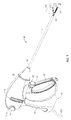
- Fig. 1 is a front, perspective view of an endoscopic surgical forceps configured for use in accordance with the present disclosure
- Fig. 5C is a bottom, perspective view of the jaw member of Fig. 5A , shown in an assembled condition;
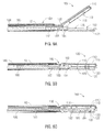
- Fig. 6C is a longitudinal, cross-sectional view of the end effector assembly of Fig. 3 with the jaw members disposed in an approximated position and with the knife blade disposed in an extended position;
- Fig. 7B is a longitudinal, cross-sectional view of the knife assembly Fig. 7A , shown in position for assembly;
- electrosurgical energy may be supplied to one (or both) of tissue-sealing plates 112, 122 and through tissue to effect a tissue seal. Controlling the gap distance "g" between sealing plates 112 and 122 helps to ensure that an effective tissue seal is achieved.
- a knife blade 182 ( Figs. 6A-6C ) may be advanced through knife channels 125, 126e of seal plate 122 and insulator 126, respectively, (and/or knife channel 115 of jaw member 110 ( Figs. 6A-6C )) to divide tissue along the previously formed tissue seal.
- knife assembly 180 is shown in use in conjunction with end effector assembly 100.
- end effector assembly 100 is maneuvered into position such that tissue to be grasped, sealed, and or cut, is disposed between jaw members 110, 120.
- moveable handle 40 Fig. 1
- fixed handle 50 Fig. 1
- jaw member 110 is pivoted relative to jaw member 120 from the spaced-apart position to the approximated position to grasp tissue therebetween (see Fig. 6B ).
Landscapes
- Health & Medical Sciences (AREA)
- Surgery (AREA)
- Engineering & Computer Science (AREA)
- Life Sciences & Earth Sciences (AREA)
- Biomedical Technology (AREA)
- Otolaryngology (AREA)
- Nuclear Medicine, Radiotherapy & Molecular Imaging (AREA)
- Plasma & Fusion (AREA)
- Physics & Mathematics (AREA)
- Heart & Thoracic Surgery (AREA)
- Medical Informatics (AREA)
- Molecular Biology (AREA)
- Animal Behavior & Ethology (AREA)
- General Health & Medical Sciences (AREA)
- Public Health (AREA)
- Veterinary Medicine (AREA)
- Surgical Instruments (AREA)
Abstract
Description
- The present disclosure relates to surgical instruments and, more particularly, to surgical forceps and methods of manufacturing surgical forceps.
- A forceps is a plier-like instrument which relies on mechanical action between its jaws to grasp, clamp and constrict vessels or tissue. Electrosurgical forceps utilize both mechanical clamping action and electrical energy to affect hemostasis by heating tissue and blood vessels to coagulate and/or cauterize tissue. Certain surgical procedures require more than simply cauterizing tissue and rely on the unique combination of clamping pressure, precise electrosurgical energy control and gap distance (i.e., distance between opposing jaw members when closed about tissue) to "seal" tissue, vessels and certain vascular bundles. Typically, once a vessel is sealed, the surgeon has to accurately sever the vessel along the newly formed tissue seal. Accordingly, many vessel sealing instruments have been designed which incorporate a knife or blade member that effectively severs the tissue after forming a tissue seal.
- In accordance with one embodiment of the present disclosure, a forceps is provided. The forceps includes an end effector assembly having first and second jaw members. One (or both) of the jaw members is movable relative to the other between a spaced-apart position and an approximated position for grasping tissue therebetween. One (or both) of the jaw members includes an insulator and a tissue-sealing plate. The insulator includes one or more engagement knobs extending therefrom. The tissue-sealing plate defines a tissue-sealing surface and includes one or more engagement apertures extending therethrough. The engagement aperture is configured to receive the engagement knob upon positioning of the tissue-sealing plate atop the insulator such that a free end of the engagement knob extends through the engagement aperture and extends from the tissue-sealing surface. The engagement knob is deformable from a first configuration, wherein the free end of the engagement knob is freely removable from the engagement aperture, to a second configuration, wherein the free end of the engagement knob is permanently inhibited from passing through the engagement aperture, thereby engaging the insulator and the tissue sealing plate to one another.
- In one embodiment, in the second configuration, the free end of the engagement knob protrudes a pre-determined distance from the tissue-sealing surface to set a gap distance between the jaw members when the jaw members are disposed in the approximated position. The gap distance may be in the range of about 0.001 inches to about 0.006 inches. Further, the engagement knob(s) may be formed from a resiliently compressible material to set the gap distance between the jaw members in accordance with a closure pressure between the jaw members.
- In another embodiment, the free end of the at least one engagement knob is deformed from the first configuration to the second configuration via heat staking.
- In still another embodiment, the forceps includes a knife assembly. The knife assembly includes a knife bar and a knife blade. The knife bar is selectively translatable relative to the end effector assembly to translate the knife blade between a retracted position and an extended position, wherein the knife blade extends between the jaw members to cut tissue grasped therebetween. Further, the knife blade and the knife bar may be secured to one another via heat staking.
- In still yet another embodiment, the free end of the engagement knob is deformable from a first diameter "d," allowing free passage of the engagement knob through the engagement aperture, to a second diameter "D," preventing passage of the engagement knob through the engagement aperture.
- Another embodiment of a forceps is provided in accordance with the present disclosure. This embodiment includes an end effector assembly having first and second jaw members. One or both of the jaw members is movable relative to the other between a spaced-apart position and an approximated position for grasping tissue therebetween. One or both of the jaw members includes a jaw frame and an insulator. The jaw frame includes one or more engagement apertures defined therethrough. The insulator includes one or more engagement knobs extending therefrom. The engagement knob is configured for insertion through the engagement aperture upon positioning of the insulator atop the jaw frame. A free end of the engagement knob is configured to extend through the engagement aperture and to extend from a surface of the jaw frame. The free end of the engagement knob is deformable from a first configuration, wherein the free end of the engagement knob is freely removable from the engagement aperture, to a second configuration, wherein the free end of the engagement knob is permanently inhibited from passing through the engagement aperture, thereby engaging the insulator and the jaw frame to one another.
- In one embodiment, the free end of the engagement knob is deformed from the first configuration to the second configuration via heat staking.
- In another embodiment, the jaw frames defines a lip disposed about a periphery of the engagement aperture on an underside of the jaw frame. The lip is configured to receive the free end of the engagement knob therein when the engagement knob is disposed in the second configuration. Further, in the second configuration, the free end of the engagement knob may be disposed within the lip such that the free end of the engagement knob is substantially flush with the jaw frame along a surface thereof.
- In still yet another embodiment, the free end of the engagement knob is deformable from a first diameter "d," allowing free passage of the engagement knob through the engagement aperture, to a second diameter "D," preventing passage of the engagement knob through the engagement aperture.
- In an embodiment, one or both jaw members include a tissue sealing plate positioned atop the insulator and preferably engaged thereto in the manner described above, particularly having deformed an engagement knob of the insulator received in an aperture of the sealing plate from the first configuration to the second configuration.
- Another embodiment provides a forceps, comprising:
- an end effector assembly including first and second jaw members, at least one of the jaw members movable relative to the other between a spaced-apart position and an approximated position for grasping tissue therebetween, at least one of the jaw members including:
- an insulator including at least one engagement knob extending therefrom;
- a tissue-sealing plate defining a tissue-sealing surface, the tissue-sealing plate positioned atop the insulator, the tissue-sealing plate including at least one engagement aperture extending therethrough that receives the at least one engagement knob , the at least one engagement knob having been deformed from a first configuration, wherein a free end of the at least one engagement knob extends through the at least one engagement aperture and extends from the tissue-sealing surface and the free end of the at least one engagement knob is freely removable from the at least one engagement aperture, to a second configuration, wherein the free end of the at least one engagement knob is permanently inhibited from passing through the at least one engagement aperture, thereby engaging the insulator and the tissue-sealing plate to one another.
- Another embodiment provides a forceps, comprising:
- an end effector assembly including first and second jaw members, at least one of the jaw members movable relative to the other between a spaced-apart position and an approximated position for grasping tissue therebetween, at least one of the jaw members including:
- a jaw frame including at least one engagement aperture defined therethrough;
- an insulator including at least one engagement knob extending therefrom, the insulator positioned atop the jaw frame, the engagement knob inserted through the at least one engagement aperture of the jaw frame, a free end of the at least one engagement knob having been deformed from a first configuration, wherein the free end of the at least one engagement knob extends through the at least one engagement aperture and extends from a surface of the jaw frame and the free end of the at least one engagement knob is freely removable from the at least one engagement aperture, to a second configuration, wherein the free end of the at least one engagement knob is permanently inhibited from passing through the at least one engagement aperture, thereby engaging the insulator and the jaw frame to one another.
- A method of manufacturing an end effector assembly of a forceps is also provided in accordance with the present disclosure. The method includes providing an insulator having one or more engagement knobs extending therefrom. The engagement knob defines a diameter "d." The method further includes providing a tissue-sealing plate defining a tissue-sealing surface and having one or more engagement apertures defined therethrough. Next, the tissue-sealing plate is positioned about the insulator such that the engagement knob is inserted through the engagement aperture with a free end of the engagement knob extending through engagement aperture and extending from the tissue-sealing surface of the tissue-sealing plate. Thereafter, the free end of the engagement knob is deformed from a first configuration having the diameter "d" which is less than a diameter of the engagement aperture, to a second configuration having a diameter "D," which is greater than the diameter of the engagement aperture, thereby preventing the engagement knob from passing through the engagement aperture and securing the insulator and the sealing plate to one another.
- In one embodiment, the free end of the engagement knob is deformed via heat-staking. More particularly, the free end of the engagement knob may be heated using a heat-staking element having a pre-determined shape such that, in the second configuration, the free end of the engagement knob defines a shape complementary to the pre-determined shape of the heat-staking element. The tissue-sealing plate and/or insulator may otherwise be configured similarly to those embodiments discussed above.
- Various embodiments of the present disclosure are described herein with reference to the drawings wherein:
-
Fig. 1 is a front, perspective view of an endoscopic surgical forceps configured for use in accordance with the present disclosure; -
Fig. 2 is a front, perspective view of an open surgical forceps configured for use in accordance with the present disclosure; -
Fig. 3 is an enlarged, front, perspective view of an end effector assembly configured for use with the forceps ofFigs. 1 and2 ; -
Fig. 4A is a transverse, cross-sectional view of one embodiment of a sealing plate and insulator configured for use with a jaw member of the end effector assembly ofFig. 3 , shown with parts separated; -
Fig. 4B is a transverse, cross-sectional view of the sealing plate and insulator ofFig. 4A shown in position for assembly; -
Fig. 4C is a transverse, cross-sectional view of the sealing plate and insulator ofFig. 4A , shown in an assembled condition; -
Fig. 5A is a side view of another embodiment of the jaw member configured for use with the end effector assembly ofFig. 3 , shown with parts separated; -
Fig. 5B is a bottom, perspective view of the jaw member ofFig. 5A , shown in position for assembly; -
Fig. 5C is a bottom, perspective view of the jaw member ofFig. 5A , shown in an assembled condition; -
Fig. 6A is a longitudinal, cross-sectional view of the end effector assembly ofFig. 3 with the jaw members disposed in a spaced-apart position; -
Fig. 6B is a longitudinal, cross-sectional view of the end effector assembly ofFig. 3 with the jaw members disposed in an approximated position and with a knife blade disposed in a retracted position; -
Fig. 6C is a longitudinal, cross-sectional view of the end effector assembly ofFig. 3 with the jaw members disposed in an approximated position and with the knife blade disposed in an extended position; -
Fig. 7A is a longitudinal, cross-sectional view of a knife assembly configured for use with the end effector assembly ofFig. 3 , shown with parts separated; -
Fig. 7B is a longitudinal, cross-sectional view of the knife assemblyFig. 7A , shown in position for assembly; and -
Fig. 7C is a longitudinal, cross-sectional view of the knife assemblyFig. 7A , shown in an assembled condition. - Embodiments of the present disclosure are described in detail with reference to the drawing figures wherein like reference numerals identify similar or identical elements. As used herein, the term "distal" refers to the portion that is being described which is further from a user, while the term "proximal" refers to the portion that is being described which is closer to a user.
- Referring now to
Figs. 1 and2 ,Fig. 1 depicts aforceps 10 for use in connection with endoscopic surgical procedures andFig. 2 depicts an open forceps 10' contemplated for use in connection with traditional open surgical procedures. For the purposes herein, either an endoscopic instrument, e.g.,forceps 10, or an open instrument, e.g., forceps 10', may be utilized in accordance with the present disclosure. Obviously, different electrical and mechanical connections and considerations apply to each particular type of instrument, however, the novel aspects with respect to the end effector assembly and its operating characteristics remain generally consistent with respect to both the open and endoscopic configurations. - Turning now to
Fig. 1 , anendoscopic forceps 10 is provided defining a longitudinal axis "X-X" and including ahousing 20, ahandle assembly 30, a rotatingassembly 70, atrigger assembly 80 and anend effector assembly 100.Forceps 10 further includes ashaft 12 having adistal end 14 configured to mechanically engageend effector assembly 100 and aproximal end 16 that mechanically engageshousing 20.Forceps 10 also includeselectrosurgical cable 610 that connectsforceps 10 to a generator (not shown) or other suitable power source, althoughforceps 10 may alternatively be configured as a battery powered instrument.Cable 610 includes a wire (or wires) (not shown) extending therethrough that has sufficient length to extend throughshaft 12 in order to provide electrical energy to at least one of the sealingplates jaw members end effector assembly 100, e.g., upon activation ofactivation switch 90. - With continued reference to
Fig. 1 , handleassembly 30 includes fixedhandle 50 and amoveable handle 40. Fixedhandle 50 is integrally associated withhousing 20 and handle 40 is moveable relative to fixedhandle 50. Rotatingassembly 70 is rotatable in either direction about longitudinal axis "X-X" to rotateend effector 100 about longitudinal axis "X-X."Housing 20 houses the internal working components offorceps 10. -
End effector assembly 100 is shown attached at adistal end 14 ofshaft 12 and includes a pair of opposingjaw members jaw members plate End effector assembly 100 is designed as a unilateral assembly, i.e., wherejaw member 120 is fixed relative toshaft 12 andjaw member 110 is moveable aboutpivot 103 relative toshaft 12 and fixedjaw member 120. However,end effector assembly 100 may alternatively be configured as a bilateral assembly, i.e., where bothjaw member 110 andjaw member 120 are moveable about apivot 103 relative to one another and toshaft 12. In some embodiments, a knife assembly 180 (Figs. 6A-6C ) is disposed withinshaft 12 and a knife channel 125 (Fig. 3 ) is defined within one or bothjaw members Fig. 6A-6C ) therethrough, e.g., via activation of atrigger 82 oftrigger assembly 80. The particular features ofend effector assembly 100 will be described in greater detail hereinbelow. - Continuing with reference to
Fig. 1 ,moveable handle 40 ofhandle assembly 30 is ultimately connected to a drive assembly (not shown) that, together, mechanically cooperate to impart movement ofjaw members plates jaw members Fig. 1 ,moveable handle 40 is initially spaced-apart from fixedhandle 50 and, correspondingly,jaw members Moveable handle 40 is actuatable from this initial position to a depressed position corresponding to the approximated position ofjaw members 110, 120 (seeFigs. 6B-6C ). - Referring now to
Fig. 2 , an open forceps 10' is shown including twoelongated shafts proximal end distal end Fig. 1 ), forceps 10' is configured for use withend effector assembly 100. More specifically,end effector assembly 100 is attached todistal ends shafts end effector assembly 100 includes a pair of opposingjaw members pivot 103. Eachshaft handle proximal end handle finger hole finger holes shafts jaw members jaw members jaw members - A ratchet 30' may be included for selectively locking the
jaw members jaw members - With continued reference to
Fig. 2 , one of the shafts, e.g.,shaft 12b, includes aproximal shaft connector 19 that is designed to connect the forceps 10' to a source of electrosurgical energy such as an electrosurgical generator (not shown).Proximal shaft connector 19 secures an electrosurgical cable 610' to forceps 10' such that the user may selectively apply electrosurgical energy to the electricallyconductive sealing plates jaw members - Forceps 10' may further include a knife assembly 180 (
Figs. 6A-6C ) disposed within either ofshafts knife channel 115, 125 (Fig. 6A ) defined within one or both ofjaw members Figs. 6A-6C ) therethrough. - Turning now to
Fig. 3 ,end effector assembly 100, includingjaw members forceps 10 or forceps 10', discussed above, or any other suitable surgical instrument capable of pivotingjaw members end effector assembly 100 will be described hereinbelow with reference toforceps 10 only. Further,jaw members jaw member 120 will be detailed below for the purposed of brevity. -
Jaw member 120, as shown inFig. 3 , includes anouter jaw housing 121 and an electrically-conductive tissue-sealingplate 122.Jaw member 120 further includes a jaw frame 124 (Figs. 5A-5C ) and an insulator 126 (Figs. 4A-4C ). Jaw frame 124 (Figs. 5A-5C ) is coupled to the jaw frame (not shown) ofjaw member 110 viapivot 103 to permit pivotable movement ofjaw members jaw member 120 thereon. Insulator 126 (Figs. 4A-4C ) is disposed on jaw frame 124 (Figs. 5A-5C ) and is configured to retain tissue-sealingplate 122 thereon.Outer jaw housing 121 is disposed about jaw frame 124 (Figs. 5A-5C ) and insulator 126 (Figs. 4A-4C ) and is configured to retain the components ofjaw member 120 therein, while tissue-sealingplate 122 defines an exposed tissue-sealing surface that opposes the tissue-sealing surface defined by tissue-sealingplate 112 ofjaw member 110, as shown inFig. 3 . Various methods and configurations for manufacturing an end effector assembly, e.g.,end effector assembly 100, or the components thereof, are described in detail hereinbelow. - Referring now to
Figs. 4A-4C , the configuration and manufacture ofinsulator 126 and sealingplate 122 ofjaw member 120 in accordance with an embodiment of the present disclosure is described.Insulator 126 is made from an electrically-insulative material and, as mentioned above, is configured to retain sealingplate 122 thereon.Insulator 126 is further configured for positioning atop jaw frame 124 (Figs. 5A-5C ) and may be secured thereto via any suitable method, e.g., heat-staking, as will be described in greater detail below. More particularly, as shown inFigs. 4A-4C ,insulator 126 includes a pair of longitudinally-extendinggrooves 126a defined at opposedlongitudinal sides 126b thereof.Grooves 126a are configured to receivewings 122a of sealingplate 122 therein upon positioning of sealingplate 122 aboutinsulator 126.Insulator 126 further includes a pair of sealing plate engagement knobs 126c extending therefrom. As best shown inFig. 3 ,insulator 126 may include several pairs of sealing plate engagement knobs 126c disposed along the length thereof, althoughinsulator 126 may also includeindividual engagement knobs 126c disposed thereon or may include sealing plate engagement knobs 126c extending therefrom in any other suitable configuration.Sealing plate 122, on the other hand, includes a plurality ofengagement apertures 122b defined therethrough, each of which is configured to receive one of the sealing plate engagement knobs 126c therein such that afree end 126d of each of the sealingplate engagement knobs 126c extends therefrom, as best shown inFig. 4B . As shown inFigs 4A-4B , sealing plate engagement knobs 126c initially define a generally uniform, cylindrical configuration to facilitate passage through the generallycircular engagement apertures 122b of sealingplate 122, although other complementary configurations may also be provided. - With continued reference to
Figs. 4A-4C , the assembly ofinsulator 126 and sealingplate 122 is described. Initially, as shown inFigs. 4A-4B , sealingplate 122 is positioned atopinsulator 126 such thatwings 122a of sealingplate 122 are disposed withingrooves 126a ofinsulator 126 and such that sealing plate engagement knobs 126c ofinsulator 126 extend through therespective engagement apertures 122b of sealingplate 122 with thefree ends 126d thereof extending fromengagement apertures 122b. As can be appreciated, a desiredsealing plate 122 andinsulator 126 may be selected, e.g., a sealingplate 122 andinsulator 126 of a specific configuration, made from a particular material, etc., such that various different combinations may be formed.Insulator 126 may further include aknife channel 126e configured to align withknife channel 125 of sealingplate 122 upon positioning of sealingplate 122 thereon to permit reciprocation of a knife blade 182 (Figs. 6A-6C ) therethrough. - Referring now to
Fig. 4B , withwings 122a of sealingplate 122 disposed withingrooves 126a ofinsulator 126 and with sealing plate engagement knobs 126c ofinsulator 126 extending throughengagement apertures 122b of sealingplate 122, sealingplate 122 andinsulator 126 are retained in fixed position relative to one another except that, at this point, sealingplate 122 may be easily separated frominsulator 126, thus returning to the position shown inFig. 4A . - In order to secure sealing
plate 122 atopinsulator 126, a heat-stakingelement 400 is used to deformfree ends 126d of sealing plate engagement knobs 126c ofinsulator 126 such that sealingplate engagement knobs 126c are inhibited from being translated back throughengagement apertures 122b, i.e., such that removal of sealingplate 122 frominsulator 126 is inhibited. More specifically, heat-stakingelement 400 includes ahead 410 that defines a dome-shaped configuration, although other configurations are contemplated. The dome-shapedhead 410 of heat-stakingelement 400 defines a diameter "D" that is greater than the diameter "d" ofengagement apertures 122b of sealingplate 122. - During assembly, the dome-shaped
head 410 of heat-stakingelement 400 is positioned aboutfree end 126d of each sealingplate engagement knob 126c and is heated to a sufficient temperature to permit deformation of sealing plate engagement knobs 126c ofinsulator 126, but such that sealingplate 122 remains substantially unaffected. As can be appreciated, the specific temperature may depend on the material(s) forminginsulator 126 and/orseal plate 122. As free ends 126d of sealingplate engagement knobs 126c are heated and, ultimately, become deformable, free ends 126d of sealing plate engagement knobs 126c conform to the dome-shapedhead 410 of heat-stakingelement 400, thereby defining a complementary dome-shaped configuration, as shown inFig. 4C . Sealingplate engagement knobs 126c are then permitted to cool such that the free ends 126d of sealing plate engagement knobs 126c retain this dome-shaped deformed configuration. In this deformed configuration, free ends 126d of sealing plate engagement knobs 126c define a dome-shaped configuration having a diameter "D," similar to that of dome-shapedhead 410 of heat-stakingelement 400. Since the deformed free ends 126d of sealing plate engagement knobs 126c define a diameter "D," that is greater than the diameter "d" ofengagement apertures 122b of sealingplate 122, free ends 126d of sealingplate engagement knobs 126c are inhibited from passing back throughengagement apertures 122b of sealingplate 122. In other words, in this position, sealingplate 122 is secured aboutinsulator 126. - Referring now to
Fig. 3 in conjunction withFig. 4C , heat-staking element 400 (Figs. 4A-4B ) may be configured such that sealingplate engagement knobs 126c, once deformed, extend a pre-determined distance "g" from the tissue-sealing surface of sealingplate 122. This pre-determined distance "g" defines a minimum gap distance "g" between the sealing surfaces of sealingplates jaw members jaw members jaw member element 400 may be configured to deform the sealing plate engagement knobs 126c to extend half the distance "g" such that, upon approximation ofjaw members plates jaw members - Additionally, or alternatively,
insulator 126, and/or sealing plate engagement knobs 126c thereof, may be formed from a resiliently compressible material to facilitate achieving a desired gap distance "g" between sealingplates jaw members jaw members jaw members jaw members - Continuing with reference to
Fig. 3 , in use, withjaw members end effector assembly 100 is positioned such that tissue to be grasped, sealed and/or divided is disposed between sealingplates jaw members jaw members plates forceps 10 from the initial position to the depressed position relative to fixed handle 50 (seeFig. 1 ). - Upon moving
jaw members jaw member 120 contact corresponding components of jaw member 110 (or simply contact sealingplate 112 of jaw member 110) to set the gap distance "g" between tissue-sealingplates jaw members plate engagement knobs 126c are resiliently compressible, upon approximation ofjaw members plate engagement knobs 126c are compressed between sealingplates jaw members jaw members plates - With tissue grasped between sealing
plates jaw members plates plates Figs. 6A-6C ) may be advanced throughknife channels seal plate 122 andinsulator 126, respectively, (and/orknife channel 115 of jaw member 110 (Figs. 6A-6C )) to divide tissue along the previously formed tissue seal. - With reference now to
Figs. 5A-5C , the configuration and assembly ofinsulator 126 and sealingplate 122 ontojaw frame 124 ofjaw member 120 in accordance with another embodiment of the present disclosure is described.Insulator 126 and sealingplate 122 may be secured to one another in any suitable fashion, e.g., heat-staking (as described above with reference toFigs. 4A-4C ), and, thus will not be described here. - As best shown in
Fig. 5A and as mentioned above,insulator 126 is configured for positioning atopjaw frame 124 and includes a pair of longitudinally-spaced jaw frame engagement knobs 126f extending therefrom, although greater or fewer than two jawframe engagement knobs 126f may be provided.Jaw frame 124, on the other hand, includes a plurality ofengagement apertures 124a defined therethrough, each of which is configured to receive one of the jaw frame engagement knobs 126f therein such that afree end 126g of each of the jawframe engagement knobs 126f extends therefrom, as best shown inFig. 5B . Engagement knobs 126f initially define a generally uniform, cylindrical configuration to facilitate passage through the generallycircular engagement apertures 124a ofjaw frame 124, although other complementary configurations may also be provided. Further,jaw frame 124 may include a recess orlip 124b defined about the periphery of each of theengagement apertures 124a on anunderside surface 124c thereof, such that, as shown inFig. 5B , free ends 126g of jawframe engagement knobs 126f are positionedadjacent lips 124b ofengagement apertures 124a when disposed throughengagement apertures 124a. - With reference now to
Figs. 5B and 5C , and initially toFig. 5B , during assembly,insulator 126 is positioned atopjaw frame 124 such that jaw frame engagement knobs 126f ofinsulator 126 are disposed throughengagement apertures 124a ofjaw frame 124, withfree ends 126g of jaw frame engagement knobs 126f extending therefrom. In order to secureinsulator 126 aboutjaw frame 124, a heat-staking element (similar to heat-staking element 400 (Fig. 4A ) is used to deformfree ends 126g of jaw frame engagement knobs 126f ofinsulator 126 such that jawframe engagement knobs 126f are inhibited from being translated back throughengagement apertures 124a, similarly as discussed above with regard toinsulator 126 andseal plate 122. More specifically, the heat-staking element is positioned about free ends 126g of each jawframe engagement knob 126f and is heated to a sufficient temperature to deform jaw frame engagement knobs 126f ofinsulator 126, without substantially affectingjaw frame 124. As free ends 126g of jawframe engagement knobs 126f are heated to achieve a state of deformability, free ends 126g of jawframe engagement knobs 126f conform tolips 124b ofjaw frame 124, which are disposed aboutengagement apertures 124a, as shown inFig. 5C . Jawframe engagement knobs 126f are then permitted to cool such that the free ends 126g thereof are retained withinlips 124b ofjaw frame 124. The heat-staking element (not shown) may define a working surface that is shaped complementary to theunderside surface 124c ofjaw frame 124 such that, in the deformed configuration, as shown inFig. 5C , free ends 126g of jawframe engagement knobs 126f are substantially flush with theunderside surface 124c ofjaw frame 124, i.e., such that free ends 126g of jawframe engagement knobs 126f are completely disposed withinlips 124b ofjaw frame 124. As can be appreciated, in this deformed configuration, free ends 126g of jawframe engagement knobs 126f are inhibited from passing back throughengagement apertures 124a ofjaw frame 124, thus securinginsulator 126 atopjaw frame 124. - Referring now to
Figs. 6A-6C ,knife assembly 180 is shown in use in conjunction withend effector assembly 100. In use, as shown inFig. 6A and as mentioned above, withjaw members end effector assembly 100 is maneuvered into position such that tissue to be grasped, sealed, and or cut, is disposed betweenjaw members Fig. 1 ) is pulled proximally relative to fixed handle 50 (Fig. 1 ) such thatjaw member 110 is pivoted relative tojaw member 120 from the spaced-apart position to the approximated position to grasp tissue therebetween (seeFig. 6B ). Thereafter, electrosurgical energy may be supplied, e.g., via activation of switch 90 (Fig. 1 ), to tissue-sealingplate 112 and/or tissue-sealingplate 122 and conducted through tissue to effect a tissue seal, as discussed above. As shown inFig. 6C ,knife blade 182 may then be advanced from the retracted position (Fig. 6B ) to the extended position (Fig. 6C ), e.g., via activation oftrigger 82 of trigger assembly 80 (Fig. 1 ), and throughblade channels jaw members jaw members 110, 120 (or to cut untreated tissue, depending on a particular purpose). - With continued reference to
Figs. 6A-6C ,knife assembly 180 includes aknife blade 182 defining adistal cutting edge 184 at thedistal end 183 thereof.Knife blade 182 is coupled to aknife bar 186 at theproximal end 185 thereof.Knife bar 186 is selectively translatable, e.g., upon activation of trigger 82 (Fig. 1 ), throughshaft 12 and relative to endeffector assembly 100 to translateknife blade 182 from the retracted position (Fig. 6B ) to the extended position (Fig. 6C ). - Turning now to
Figs. 7A-7C , the configuration and assembly ofknife assembly 180 in accordance with embodiments of the present disclosure will be described. As best shown inFig. 7A ,knife bar 186 includes anengagement knob 187 disposed atdistal end 188 thereof.Engagement knob 187 is configured for insertion through a complementary-shapedengagement aperture 189 defined throughknife blade 182 atproximal end 185 thereof. Similarly as described above, onceengagement knob 187 has been inserted throughengagement aperture 189, the free end ofengagement knob 187 may be deformed via heat-staking without substantially affectingknife blade 182, e.g., using heat-stakingelement 400, to secureknife bar 186 andknife blade 182 to one another. Further, althoughknife blade 182 is shown positioned atopknife bar 186 and secured thereto via a single heat-staked knob/aperture engagement, heat-staking may alternatively be used to secureknife blade 182 andknife bar 186 in any other suitable position relative to one another and/or multiple heat-staked knob/aperture engagements may be provided. - From the foregoing and with reference to the various figure drawings, those skilled in the art will appreciate that certain modifications can also be made to the present disclosure without departing from the scope of the same. While several embodiments of the disclosure have been shown in the drawings, it is not intended that the disclosure be limited thereto, as it is intended that the disclosure be as broad in scope as the art will allow and that the specification be read likewise. Therefore, the above description should not be construed as limiting, but merely as exemplifications of particular embodiments. Those skilled in the art will envision other modifications within the scope and spirit of the claims appended hereto.
-
- 1. A forceps, comprising:
- an end effector assembly including first and second jaw members, at least one of the jaw members movable relative to the other between a spaced-apart position and an approximated position for grasping tissue therebetween, at least one of the jaw members including:
- an insulator including at least one engagement knob extending therefrom;
- a tissue-sealing plate defining a tissue-sealing surface, the tissue-sealing plate including at least one engagement aperture extending therethrough that is configured to receive the at least one engagement knob upon positioning of the tissue-sealing plate atop the insulator such that a free end of the at least one engagement knob extends through the at least one engagement aperture and extends from the tissue-sealing surface, the at least one engagement knob deformable from a first configuration, wherein the free end of the at least one engagement knob is freely removable from the at least one engagement aperture, to a second configuration, wherein the free end of the at least one engagement knob is permanently inhibited from passing through the at least one engagement aperture, thereby engaging the insulator and the tissue-sealing plate to one another.
- an end effector assembly including first and second jaw members, at least one of the jaw members movable relative to the other between a spaced-apart position and an approximated position for grasping tissue therebetween, at least one of the jaw members including:
- 2. The forceps according to 1, wherein in the second configuration, the free end of the at least one engagement knob protrudes a pre-determined distance from the tissue-sealing surface to set a gap distance between the jaw members when the jaw members are disposed in the approximated position.
- 3. The forceps according to 2, wherein the gap distance is in the range of about 0.001 inches to about 0.006 inches.
- 4. The forceps according to 2, wherein the at least one engagement knob is formed at least partially from a resiliently compressible material to set the gap distance between the jaw members in accordance with a closure pressure between the jaw members.
- 5. The forceps according to 1, wherein the free end of the at least one engagement knob is deformed from the first configuration to the second configuration via heat staking.
- 6. The forceps according to 1, further comprising a knife assembly including a knife bar and a knife blade, the knife bar selectively translatable relative to the end effector assembly to translate the knife blade between a retracted position and an extended position wherein the knife blade extends between the jaw members to cut tissue grasped therebetween.
- 7. The forceps according to 6, wherein the knife blade and the knife bar are secured to one another via heat staking.
- 8. The forceps according to 1, wherein the free end of the at least one engagement knob is deformable from a first diameter "d," allowing free passage of the at least one engagement knob through the at least one engagement aperture, to a second diameter "D," preventing passage of the at least one engagement knob through the at least one engagement aperture.
- 9. A forceps, comprising:
- an end effector assembly including first and second jaw members, at least one of the jaw members movable relative to the other between a spaced-apart position and an approximated position for grasping tissue therebetween, at least one of the jaw members including:
- a jaw frame including at least one engagement aperture defined therethrough;
- an insulator including at least one engagement knob extending therefrom, the engagement knob configured for insertion through the at least one engagement aperture of the jaw frame upon positioning of the insulator atop the jaw frame, a free end of the at least one engagement knob configured to extend through the at least one engagement aperture and to extend from a surface of the jaw frame, the free end of the at least one engagement knob deformable from a first configuration, wherein the free end of the at least one engagement knob is freely removable from the at least one engagement aperture, to a second configuration, wherein the free end of the at least one engagement knob is permanently inhibited from passing through the at least one engagement aperture, thereby engaging the insulator and the jaw frame to one another.
- an end effector assembly including first and second jaw members, at least one of the jaw members movable relative to the other between a spaced-apart position and an approximated position for grasping tissue therebetween, at least one of the jaw members including:
- 10. The forceps according to 9, wherein the free end of the at least one engagement knob is deformed from the first configuration to the second configuration via heat staking.
- 11. The forceps according to 9, wherein the jaw frames defines a lip disposed about a periphery of the at least one engagement aperture on an underside of the jaw frame, the lip configured to receive the free end of the engagement knob therein when the engagement knob is disposed in the second configuration.
- 12. The forceps according to 11, wherein, in the second configuration, the free end of the engagement knob is disposed within the lip such that the free end of the engagement knob is substantially flush with the jaw frame along a surface thereof.
- 13. The forceps according to 9, further comprising a knife assembly including a knife bar and a knife blade, the knife bar selectively translatable relative to the end effector assembly to translate the knife blade between a retracted position and an extended position wherein the knife blade extends between the jaw members to cut tissue grasped therebetween.
- 14. The forceps according to 13, wherein the knife blade and the knife bar are secured to one another via heat staking.
- 15. The forceps according to 9, wherein the free end of the at least one engagement knob is deformable from a first diameter "d," allowing free passage of the at least one engagement knob through the at least one engagement aperture, to a second diameter "D," preventing passage of the at least one engagement knob through the at least one engagement aperture.
- 16. A method of manufacturing an end effector assembly of a forceps, the method comprising the steps of:
- providing an insulator including at least one engagement knob extending therefrom, the at least one engagement aperture having a diameter "d";
- providing a tissue-sealing plate having at least one engagement aperture defined therethrough and defining a tissue-sealing surface;
- positioning the tissue-sealing plate about the insulator such that the at least one engagement knob is inserted through the at least one engagement aperture and such that a free end of the at least one engagement knob extends through the at least one engagement aperture and extends from the tissue-sealing surface of the tissue-sealing plate;
- deforming the free end of the at least one engagement knob such that the free end of the at least one engagement knob is deformed from a first configuration having diameter "d" which is less than a diameter of the at least one engagement aperture, to a second configuration having a diameter "D" which is greater than the diameter of the at least one engagement aperture, thereby preventing the at least one engagement knob from passing through the at least one engagement aperture and securing the insulator and the sealing plate to one another.
- 17. The method according to 16, wherein, in the second configuration, the free end of the at least one engagement knob extends from the tissue-sealing surface to define a stop member disposed atop the tissue-sealing plate.
- 18. The method according to 17, wherein the stop member extends from the tissue-sealing surface a distance of between about 0.001 inches and about 0.006 inches.
- 19. The method according to 17, wherein the stop member is formed at least partially from a resiliently compressible material.
- 20. The method according to 16, wherein the step of deforming the free end of the at least one engagement knob is performed via heat-staking.
Claims (10)
- A forceps, comprising:an end effector assembly (100) including first and second jaw members (110, 120), at least one of the jaw members (110, 120) movable relative to the other between a spaced-apart position and an approximated position for grasping tissue therebetween, the end effector assembly (100) characterized in that at least one of the jaw members (110, 120) includes:an insulator (126) including at least one engagement knob (126c) extending therefrom; anda tissue-sealing plate (122) defining a tissue-sealing surface, the tissue-sealing plate (122) including at least one engagement aperture (122b) extending therethrough that is configured to receive the at least one engagement knob (126c) upon positioning of the tissue-sealing plate (122) atop the insulator (126) such that a free end (126d) of the at least one engagement knob (126c) extends through the at least one engagement aperture (122b) and extends from the tissue-sealing surface, the at least one engagement knob (126c) deformable from a first configuration, wherein the free end (126d) of the at least one engagement knob (126c) is freely removable from the at least one engagement aperture (122b), to a second configuration, wherein the free end (126d) of the at least one engagement knob (126c) is permanently inhibited from passing through the at least one engagement aperture (122b), thereby engaging the insulator (126) and the tissue-sealing plate (122) to one another.
- The forceps according to claim 1, wherein in the second configuration, the free end (126d) of the at least one engagement knob (126c) protrudes a pre-determined distance from the tissue-sealing surface to set a gap distance between the jaw members (110, 120) when the jaw members (110, 120) are disposed in the approximated position.
- The forceps according to claim 2 or 3, wherein the gap distance is in the range of about 0.0254mm to about 0.1524mm.
- The forceps according to claim 2, wherein the at least one engagement knob (126c) is formed at least partially from a resiliently compressible material to set the gap distance between the jaw members (110, 120) in accordance with a closure pressure between the jaw members (110, 120).
- The forceps according to any of the preceding claims, wherein the free end (126d) of the at least one engagement knob (126c) is deformed from the first configuration to the second configuration via heat staking.
- The forceps according to any of the preceding claims, wherein the free end (126d) of the at least one engagement knob (126c) is deformable from a first diameter "d," allowing free passage of the at least one engagement knob (126c) through the at least one engagement aperture (122b), to a second diameter "D," preventing passage of the at least one engagement knob (126c) through the at least one engagement aperture (122b).
- A method of manufacturing a jaw member (110, 120) of a forceps, the method comprising the steps of:providing an insulator (126) including at least one engagement knob (126c) extending therefrom, the at least one engagement knob (126c) having a diameter "d";providing a tissue-sealing plate (122) having at least one engagement aperture (122b) defined therethrough, the tissue sealing plate (122) defining a tissue-sealing surface;positioning the tissue-sealing plate (122) about the insulator (126) such that the at least one engagement knob (126c) is inserted through the at least one engagement aperture (122b) and such that a free end (126d) of the at least one engagement knob (126c) extends through the at least one engagement aperture (122b) and extends from the tissue-sealing surface of the tissue-sealing plate (122); anddeforming the free end (126d) of the at least one engagement knob (126c) such that the free end (126d) of the at least one engagement knob (126c) is deformed from a first configuration having diameter "d" which is less than a diameter of the at least one engagement aperture (122b), to a second configuration having a diameter "D" which is greater than the diameter of the at least one engagement aperture (122b), thereby preventing the at least one engagement knob (126c) from passing through the at least one engagement aperture (122b) and securing the insulator (126) and the sealing plate (122) to one another.
- The method according to claim 7, wherein, in the second configuration, the free end (126d) of the at least one engagement knob (126c) extends from the tissue-sealing surface to define a stop member disposed atop the tissue-sealing plate (122).
- The method according to claim 8, wherein the stop member extends from the tissue-sealing surface a distance of between about 0.0254mm and about 0.1524mm.
- The method according to any of claims 7-9, wherein the step of deforming the free end (126d) of the at least one engagement knob (126c) is performed via heat-staking.
Applications Claiming Priority (1)
| Application Number | Priority Date | Filing Date | Title |
|---|---|---|---|
| US13/085,144 US20120265241A1 (en) | 2011-04-12 | 2011-04-12 | Surgical Forceps and Method of Manufacturing Thereof |
Publications (3)
| Publication Number | Publication Date |
|---|---|
| EP2510890A2 true EP2510890A2 (en) | 2012-10-17 |
| EP2510890A3 EP2510890A3 (en) | 2017-07-12 |
| EP2510890B1 EP2510890B1 (en) | 2022-08-03 |
Family
ID=46000869
Family Applications (1)
| Application Number | Title | Priority Date | Filing Date |
|---|---|---|---|
| EP12163881.1A Active EP2510890B1 (en) | 2011-04-12 | 2012-04-12 | Surgical forceps and method of manufacturing thereof |
Country Status (3)
| Country | Link |
|---|---|
| US (1) | US20120265241A1 (en) |
| EP (1) | EP2510890B1 (en) |
| CN (1) | CN102727283B (en) |
Cited By (1)
| Publication number | Priority date | Publication date | Assignee | Title |
|---|---|---|---|---|
| EP4035618A1 (en) * | 2021-02-01 | 2022-08-03 | Covidien LP | Electrosurgical instruments, jaw members thereof, and methods of manufacturing |
Families Citing this family (227)
| Publication number | Priority date | Publication date | Assignee | Title |
|---|---|---|---|---|
| US7364577B2 (en) | 2002-02-11 | 2008-04-29 | Sherwood Services Ag | Vessel sealing system |
| AU2001249933B2 (en) | 2001-04-06 | 2006-06-08 | Covidien Ag | Vessel sealer and divider with non-conductive stop members |
| US10835307B2 (en) | 2001-06-12 | 2020-11-17 | Ethicon Llc | Modular battery powered handheld surgical instrument containing elongated multi-layered shaft |
| US8182501B2 (en) | 2004-02-27 | 2012-05-22 | Ethicon Endo-Surgery, Inc. | Ultrasonic surgical shears and method for sealing a blood vessel using same |
| PL1802245T3 (en) | 2004-10-08 | 2017-01-31 | Ethicon Endosurgery Llc | Ultrasonic surgical instrument |
| US7628791B2 (en) | 2005-08-19 | 2009-12-08 | Covidien Ag | Single action tissue sealer |
| US20070191713A1 (en) | 2005-10-14 | 2007-08-16 | Eichmann Stephen E | Ultrasonic device for cutting and coagulating |
| US7621930B2 (en) | 2006-01-20 | 2009-11-24 | Ethicon Endo-Surgery, Inc. | Ultrasound medical instrument having a medical ultrasonic blade |
| US8298232B2 (en) | 2006-01-24 | 2012-10-30 | Tyco Healthcare Group Lp | Endoscopic vessel sealer and divider for large tissue structures |
| US8057498B2 (en) | 2007-11-30 | 2011-11-15 | Ethicon Endo-Surgery, Inc. | Ultrasonic surgical instrument blades |
| US8911460B2 (en) | 2007-03-22 | 2014-12-16 | Ethicon Endo-Surgery, Inc. | Ultrasonic surgical instruments |
| US8142461B2 (en) | 2007-03-22 | 2012-03-27 | Ethicon Endo-Surgery, Inc. | Surgical instruments |
| US8523889B2 (en) | 2007-07-27 | 2013-09-03 | Ethicon Endo-Surgery, Inc. | Ultrasonic end effectors with increased active length |
| US8808319B2 (en) | 2007-07-27 | 2014-08-19 | Ethicon Endo-Surgery, Inc. | Surgical instruments |
| US8430898B2 (en) | 2007-07-31 | 2013-04-30 | Ethicon Endo-Surgery, Inc. | Ultrasonic surgical instruments |
| US8512365B2 (en) | 2007-07-31 | 2013-08-20 | Ethicon Endo-Surgery, Inc. | Surgical instruments |
| US9044261B2 (en) | 2007-07-31 | 2015-06-02 | Ethicon Endo-Surgery, Inc. | Temperature controlled ultrasonic surgical instruments |
| AU2008308606B2 (en) | 2007-10-05 | 2014-12-18 | Ethicon Endo-Surgery, Inc. | Ergonomic surgical instruments |
| US10010339B2 (en) | 2007-11-30 | 2018-07-03 | Ethicon Llc | Ultrasonic surgical blades |
| US9089360B2 (en) | 2008-08-06 | 2015-07-28 | Ethicon Endo-Surgery, Inc. | Devices and techniques for cutting and coagulating tissue |
| US9700339B2 (en) | 2009-05-20 | 2017-07-11 | Ethicon Endo-Surgery, Inc. | Coupling arrangements and methods for attaching tools to ultrasonic surgical instruments |
| US8663220B2 (en) | 2009-07-15 | 2014-03-04 | Ethicon Endo-Surgery, Inc. | Ultrasonic surgical instruments |
| US8430876B2 (en) | 2009-08-27 | 2013-04-30 | Tyco Healthcare Group Lp | Vessel sealer and divider with knife lockout |
| US8133254B2 (en) | 2009-09-18 | 2012-03-13 | Tyco Healthcare Group Lp | In vivo attachable and detachable end effector assembly and laparoscopic surgical instrument and methods therefor |
| US8112871B2 (en) | 2009-09-28 | 2012-02-14 | Tyco Healthcare Group Lp | Method for manufacturing electrosurgical seal plates |
| US11090104B2 (en) | 2009-10-09 | 2021-08-17 | Cilag Gmbh International | Surgical generator for ultrasonic and electrosurgical devices |
| US10172669B2 (en) | 2009-10-09 | 2019-01-08 | Ethicon Llc | Surgical instrument comprising an energy trigger lockout |
| US8956349B2 (en) | 2009-10-09 | 2015-02-17 | Ethicon Endo-Surgery, Inc. | Surgical generator for ultrasonic and electrosurgical devices |
| US10441345B2 (en) | 2009-10-09 | 2019-10-15 | Ethicon Llc | Surgical generator for ultrasonic and electrosurgical devices |
| US8486096B2 (en) | 2010-02-11 | 2013-07-16 | Ethicon Endo-Surgery, Inc. | Dual purpose surgical instrument for cutting and coagulating tissue |
| US8951272B2 (en) | 2010-02-11 | 2015-02-10 | Ethicon Endo-Surgery, Inc. | Seal arrangements for ultrasonically powered surgical instruments |
| US8469981B2 (en) | 2010-02-11 | 2013-06-25 | Ethicon Endo-Surgery, Inc. | Rotatable cutting implement arrangements for ultrasonic surgical instruments |
| US8834518B2 (en) | 2010-04-12 | 2014-09-16 | Ethicon Endo-Surgery, Inc. | Electrosurgical cutting and sealing instruments with cam-actuated jaws |
| GB2480498A (en) | 2010-05-21 | 2011-11-23 | Ethicon Endo Surgery Inc | Medical device comprising RF circuitry |
| US8795327B2 (en) | 2010-07-22 | 2014-08-05 | Ethicon Endo-Surgery, Inc. | Electrosurgical instrument with separate closure and cutting members |
| US9192431B2 (en) | 2010-07-23 | 2015-11-24 | Ethicon Endo-Surgery, Inc. | Electrosurgical cutting and sealing instrument |
| US8939972B2 (en) | 2011-05-06 | 2015-01-27 | Covidien Lp | Surgical forceps |
| US8685009B2 (en) | 2011-05-16 | 2014-04-01 | Covidien Lp | Thread-like knife for tissue cutting |
| US9615877B2 (en) | 2011-06-17 | 2017-04-11 | Covidien Lp | Tissue sealing forceps |
| US8745840B2 (en) | 2011-07-11 | 2014-06-10 | Covidien Lp | Surgical forceps and method of manufacturing thereof |
| US9039732B2 (en) | 2011-07-11 | 2015-05-26 | Covidien Lp | Surgical forceps |
| US9259265B2 (en) | 2011-07-22 | 2016-02-16 | Ethicon Endo-Surgery, Llc | Surgical instruments for tensioning tissue |
| US9044243B2 (en) | 2011-08-30 | 2015-06-02 | Ethcon Endo-Surgery, Inc. | Surgical cutting and fastening device with descendible second trigger arrangement |
| WO2013062978A2 (en) | 2011-10-24 | 2013-05-02 | Ethicon Endo-Surgery, Inc. | Medical instrument |
| US8968310B2 (en) | 2011-11-30 | 2015-03-03 | Covidien Lp | Electrosurgical instrument with a knife blade lockout mechanism |
| US9113897B2 (en) | 2012-01-23 | 2015-08-25 | Covidien Lp | Partitioned surgical instrument |
| US8968360B2 (en) | 2012-01-25 | 2015-03-03 | Covidien Lp | Surgical instrument with resilient driving member and related methods of use |
| JP6165780B2 (en) | 2012-02-10 | 2017-07-19 | エシコン・エンド−サージェリィ・インコーポレイテッドEthicon Endo−Surgery,Inc. | Robot-controlled surgical instrument |
| US8747434B2 (en) | 2012-02-20 | 2014-06-10 | Covidien Lp | Knife deployment mechanisms for surgical forceps |
| US8887373B2 (en) | 2012-02-24 | 2014-11-18 | Covidien Lp | Vessel sealing instrument with reduced thermal spread and method of manufacture therefor |
| US8961514B2 (en) * | 2012-03-06 | 2015-02-24 | Covidien Lp | Articulating surgical apparatus |
| US9265569B2 (en) | 2012-03-29 | 2016-02-23 | Covidien Lp | Method of manufacturing an electrosurgical forceps |
| US9439668B2 (en) | 2012-04-09 | 2016-09-13 | Ethicon Endo-Surgery, Llc | Switch arrangements for ultrasonic surgical instruments |
| US8968311B2 (en) | 2012-05-01 | 2015-03-03 | Covidien Lp | Surgical instrument with stamped double-flag jaws and actuation mechanism |
| US9820765B2 (en) | 2012-05-01 | 2017-11-21 | Covidien Lp | Surgical instrument with stamped double-flange jaws |
| US9668807B2 (en) | 2012-05-01 | 2017-06-06 | Covidien Lp | Simplified spring load mechanism for delivering shaft force of a surgical instrument |
| US20140005705A1 (en) | 2012-06-29 | 2014-01-02 | Ethicon Endo-Surgery, Inc. | Surgical instruments with articulating shafts |
| US9226767B2 (en) | 2012-06-29 | 2016-01-05 | Ethicon Endo-Surgery, Inc. | Closed feedback control for electrosurgical device |
| US9393037B2 (en) | 2012-06-29 | 2016-07-19 | Ethicon Endo-Surgery, Llc | Surgical instruments with articulating shafts |
| US20140005702A1 (en) | 2012-06-29 | 2014-01-02 | Ethicon Endo-Surgery, Inc. | Ultrasonic surgical instruments with distally positioned transducers |
| US9408622B2 (en) | 2012-06-29 | 2016-08-09 | Ethicon Endo-Surgery, Llc | Surgical instruments with articulating shafts |
| US9326788B2 (en) | 2012-06-29 | 2016-05-03 | Ethicon Endo-Surgery, Llc | Lockout mechanism for use with robotic electrosurgical device |
| US9198714B2 (en) | 2012-06-29 | 2015-12-01 | Ethicon Endo-Surgery, Inc. | Haptic feedback devices for surgical robot |
| US9351754B2 (en) | 2012-06-29 | 2016-05-31 | Ethicon Endo-Surgery, Llc | Ultrasonic surgical instruments with distally positioned jaw assemblies |
| US9820768B2 (en) | 2012-06-29 | 2017-11-21 | Ethicon Llc | Ultrasonic surgical instruments with control mechanisms |
| JP6275727B2 (en) | 2012-09-28 | 2018-02-07 | エシコン・エンド−サージェリィ・インコーポレイテッドEthicon Endo−Surgery,Inc. | Multifunctional bipolar forceps |
| US9265566B2 (en) | 2012-10-16 | 2016-02-23 | Covidien Lp | Surgical instrument |
| US9095367B2 (en) | 2012-10-22 | 2015-08-04 | Ethicon Endo-Surgery, Inc. | Flexible harmonic waveguides/blades for surgical instruments |
| US20140135804A1 (en) | 2012-11-15 | 2014-05-15 | Ethicon Endo-Surgery, Inc. | Ultrasonic and electrosurgical devices |
| US10226273B2 (en) | 2013-03-14 | 2019-03-12 | Ethicon Llc | Mechanical fasteners for use with surgical energy devices |
| EP3488805A1 (en) | 2013-08-07 | 2019-05-29 | Covidien LP | Bipolar surgical instrument |
| US10751110B2 (en) | 2013-08-07 | 2020-08-25 | Covidien Lp | Bipolar surgical instrument with tissue stop |
| US9814514B2 (en) | 2013-09-13 | 2017-11-14 | Ethicon Llc | Electrosurgical (RF) medical instruments for cutting and coagulating tissue |
| USD788302S1 (en) | 2013-10-01 | 2017-05-30 | Covidien Lp | Knife for endoscopic electrosurgical forceps |
| JP2016530968A (en) * | 2013-10-10 | 2016-10-06 | ジャイラス エーシーエムアイ インク | Laparoscopic forceps assembly |
| US9265926B2 (en) | 2013-11-08 | 2016-02-23 | Ethicon Endo-Surgery, Llc | Electrosurgical devices |
| GB2521229A (en) | 2013-12-16 | 2015-06-17 | Ethicon Endo Surgery Inc | Medical device |
| GB2521228A (en) | 2013-12-16 | 2015-06-17 | Ethicon Endo Surgery Inc | Medical device |
| US9795436B2 (en) | 2014-01-07 | 2017-10-24 | Ethicon Llc | Harvesting energy from a surgical generator |
| US9554854B2 (en) | 2014-03-18 | 2017-01-31 | Ethicon Endo-Surgery, Llc | Detecting short circuits in electrosurgical medical devices |
| US10092310B2 (en) | 2014-03-27 | 2018-10-09 | Ethicon Llc | Electrosurgical devices |
| US10463421B2 (en) | 2014-03-27 | 2019-11-05 | Ethicon Llc | Two stage trigger, clamp and cut bipolar vessel sealer |
| US10524852B1 (en) | 2014-03-28 | 2020-01-07 | Ethicon Llc | Distal sealing end effector with spacers |
| US9737355B2 (en) | 2014-03-31 | 2017-08-22 | Ethicon Llc | Controlling impedance rise in electrosurgical medical devices |
| US9913680B2 (en) | 2014-04-15 | 2018-03-13 | Ethicon Llc | Software algorithms for electrosurgical instruments |
| US9757186B2 (en) | 2014-04-17 | 2017-09-12 | Ethicon Llc | Device status feedback for bipolar tissue spacer |
| US10285724B2 (en) | 2014-07-31 | 2019-05-14 | Ethicon Llc | Actuation mechanisms and load adjustment assemblies for surgical instruments |
| US10194976B2 (en) | 2014-08-25 | 2019-02-05 | Ethicon Llc | Lockout disabling mechanism |
| US9877776B2 (en) | 2014-08-25 | 2018-01-30 | Ethicon Llc | Simultaneous I-beam and spring driven cam jaw closure mechanism |
| US10194972B2 (en) | 2014-08-26 | 2019-02-05 | Ethicon Llc | Managing tissue treatment |
| US10039592B2 (en) | 2014-09-17 | 2018-08-07 | Covidien Lp | Deployment mechanisms for surgical instruments |
| US9918785B2 (en) | 2014-09-17 | 2018-03-20 | Covidien Lp | Deployment mechanisms for surgical instruments |
| US9987076B2 (en) | 2014-09-17 | 2018-06-05 | Covidien Lp | Multi-function surgical instruments |
| US10039593B2 (en) | 2014-09-17 | 2018-08-07 | Covidien Lp | Surgical instrument having a bipolar end effector assembly and a deployable monopolar assembly |
| US10080605B2 (en) | 2014-09-17 | 2018-09-25 | Covidien Lp | Deployment mechanisms for surgical instruments |
| US10639092B2 (en) | 2014-12-08 | 2020-05-05 | Ethicon Llc | Electrode configurations for surgical instruments |
| US9848937B2 (en) | 2014-12-22 | 2017-12-26 | Ethicon Llc | End effector with detectable configurations |
| US10092348B2 (en) | 2014-12-22 | 2018-10-09 | Ethicon Llc | RF tissue sealer, shear grip, trigger lock mechanism and energy activation |
| US10159524B2 (en) | 2014-12-22 | 2018-12-25 | Ethicon Llc | High power battery powered RF amplifier topology |
| US10111699B2 (en) | 2014-12-22 | 2018-10-30 | Ethicon Llc | RF tissue sealer, shear grip, trigger lock mechanism and energy activation |
| GB2535006B (en) * | 2015-01-14 | 2018-12-12 | Gyrus Medical Ltd | End effector for electrosurgical instrument |
| GB2535003B (en) | 2015-01-14 | 2018-12-12 | Gyrus Medical Ltd | Electrosurgical instrument |
| GB2545135B (en) | 2015-01-14 | 2018-01-24 | Gyrus Medical Ltd | Electrosurgical system |
| GB2534147B (en) | 2015-01-14 | 2018-11-14 | Gyrus Medical Ltd | Manufacturing electrosurgical instruments |
| US10245095B2 (en) | 2015-02-06 | 2019-04-02 | Ethicon Llc | Electrosurgical instrument with rotation and articulation mechanisms |
| US10342602B2 (en) | 2015-03-17 | 2019-07-09 | Ethicon Llc | Managing tissue treatment |
| US10321950B2 (en) | 2015-03-17 | 2019-06-18 | Ethicon Llc | Managing tissue treatment |
| US10595929B2 (en) | 2015-03-24 | 2020-03-24 | Ethicon Llc | Surgical instruments with firing system overload protection mechanisms |
| US10314638B2 (en) | 2015-04-07 | 2019-06-11 | Ethicon Llc | Articulating radio frequency (RF) tissue seal with articulating state sensing |
| US10117702B2 (en) | 2015-04-10 | 2018-11-06 | Ethicon Llc | Surgical generator systems and related methods |
| US10130410B2 (en) | 2015-04-17 | 2018-11-20 | Ethicon Llc | Electrosurgical instrument including a cutting member decouplable from a cutting member trigger |
| US9872725B2 (en) | 2015-04-29 | 2018-01-23 | Ethicon Llc | RF tissue sealer with mode selection |
| US11020140B2 (en) | 2015-06-17 | 2021-06-01 | Cilag Gmbh International | Ultrasonic surgical blade for use with ultrasonic surgical instruments |
| US11141213B2 (en) | 2015-06-30 | 2021-10-12 | Cilag Gmbh International | Surgical instrument with user adaptable techniques |
| US10898256B2 (en) | 2015-06-30 | 2021-01-26 | Ethicon Llc | Surgical system with user adaptable techniques based on tissue impedance |
| US11051873B2 (en) | 2015-06-30 | 2021-07-06 | Cilag Gmbh International | Surgical system with user adaptable techniques employing multiple energy modalities based on tissue parameters |
| US10357303B2 (en) | 2015-06-30 | 2019-07-23 | Ethicon Llc | Translatable outer tube for sealing using shielded lap chole dissector |
| US10034704B2 (en) | 2015-06-30 | 2018-07-31 | Ethicon Llc | Surgical instrument with user adaptable algorithms |
| US11129669B2 (en) | 2015-06-30 | 2021-09-28 | Cilag Gmbh International | Surgical system with user adaptable techniques based on tissue type |
| US10154852B2 (en) | 2015-07-01 | 2018-12-18 | Ethicon Llc | Ultrasonic surgical blade with improved cutting and coagulation features |
| USD844139S1 (en) | 2015-07-17 | 2019-03-26 | Covidien Lp | Monopolar assembly of a multi-function surgical instrument |
| USD844138S1 (en) | 2015-07-17 | 2019-03-26 | Covidien Lp | Handle assembly of a multi-function surgical instrument |
| US10987159B2 (en) | 2015-08-26 | 2021-04-27 | Covidien Lp | Electrosurgical end effector assemblies and electrosurgical forceps configured to reduce thermal spread |
| US10736685B2 (en) | 2015-09-30 | 2020-08-11 | Ethicon Llc | Generator for digitally generating combined electrical signal waveforms for ultrasonic surgical instruments |
| US10595930B2 (en) | 2015-10-16 | 2020-03-24 | Ethicon Llc | Electrode wiping surgical device |
| US10959771B2 (en) | 2015-10-16 | 2021-03-30 | Ethicon Llc | Suction and irrigation sealing grasper |
| US10959806B2 (en) | 2015-12-30 | 2021-03-30 | Ethicon Llc | Energized medical device with reusable handle |
| US10179022B2 (en) | 2015-12-30 | 2019-01-15 | Ethicon Llc | Jaw position impedance limiter for electrosurgical instrument |
| US10575892B2 (en) | 2015-12-31 | 2020-03-03 | Ethicon Llc | Adapter for electrical surgical instruments |
| US11129670B2 (en) | 2016-01-15 | 2021-09-28 | Cilag Gmbh International | Modular battery powered handheld surgical instrument with selective application of energy based on button displacement, intensity, or local tissue characterization |
| US10828058B2 (en) | 2016-01-15 | 2020-11-10 | Ethicon Llc | Modular battery powered handheld surgical instrument with motor control limits based on tissue characterization |
| US11229471B2 (en) | 2016-01-15 | 2022-01-25 | Cilag Gmbh International | Modular battery powered handheld surgical instrument with selective application of energy based on tissue characterization |
| US12193698B2 (en) | 2016-01-15 | 2025-01-14 | Cilag Gmbh International | Method for self-diagnosing operation of a control switch in a surgical instrument system |
| US10716615B2 (en) | 2016-01-15 | 2020-07-21 | Ethicon Llc | Modular battery powered handheld surgical instrument with curved end effectors having asymmetric engagement between jaw and blade |
| US10426543B2 (en) | 2016-01-23 | 2019-10-01 | Covidien Lp | Knife trigger for vessel sealer |
| US10555769B2 (en) | 2016-02-22 | 2020-02-11 | Ethicon Llc | Flexible circuits for electrosurgical instrument |
| US10537381B2 (en) | 2016-02-26 | 2020-01-21 | Covidien Lp | Surgical instrument having a bipolar end effector assembly and a deployable monopolar assembly |
| US10646269B2 (en) | 2016-04-29 | 2020-05-12 | Ethicon Llc | Non-linear jaw gap for electrosurgical instruments |
| US10987156B2 (en) | 2016-04-29 | 2021-04-27 | Ethicon Llc | Electrosurgical instrument with electrically conductive gap setting member and electrically insulative tissue engaging members |
| US10856934B2 (en) | 2016-04-29 | 2020-12-08 | Ethicon Llc | Electrosurgical instrument with electrically conductive gap setting and tissue engaging members |
| US10485607B2 (en) | 2016-04-29 | 2019-11-26 | Ethicon Llc | Jaw structure with distal closure for electrosurgical instruments |
| US10702329B2 (en) | 2016-04-29 | 2020-07-07 | Ethicon Llc | Jaw structure with distal post for electrosurgical instruments |
| US10456193B2 (en) | 2016-05-03 | 2019-10-29 | Ethicon Llc | Medical device with a bilateral jaw configuration for nerve stimulation |
| US11076908B2 (en) | 2016-06-02 | 2021-08-03 | Gyrus Acmi, Inc. | Two-stage electrosurgical device for vessel sealing |
| US10245064B2 (en) | 2016-07-12 | 2019-04-02 | Ethicon Llc | Ultrasonic surgical instrument with piezoelectric central lumen transducer |
| US10893883B2 (en) | 2016-07-13 | 2021-01-19 | Ethicon Llc | Ultrasonic assembly for use with ultrasonic surgical instruments |
| US10842522B2 (en) | 2016-07-15 | 2020-11-24 | Ethicon Llc | Ultrasonic surgical instruments having offset blades |
| US10376305B2 (en) | 2016-08-05 | 2019-08-13 | Ethicon Llc | Methods and systems for advanced harmonic energy |
| US10285723B2 (en) | 2016-08-09 | 2019-05-14 | Ethicon Llc | Ultrasonic surgical blade with improved heel portion |
| US10631887B2 (en) | 2016-08-15 | 2020-04-28 | Covidien Lp | Electrosurgical forceps for video assisted thoracoscopic surgery and other surgical procedures |
| USD847990S1 (en) | 2016-08-16 | 2019-05-07 | Ethicon Llc | Surgical instrument |
| US10736649B2 (en) | 2016-08-25 | 2020-08-11 | Ethicon Llc | Electrical and thermal connections for ultrasonic transducer |
| US10952759B2 (en) | 2016-08-25 | 2021-03-23 | Ethicon Llc | Tissue loading of a surgical instrument |
| US10751117B2 (en) | 2016-09-23 | 2020-08-25 | Ethicon Llc | Electrosurgical instrument with fluid diverter |
| US10603064B2 (en) | 2016-11-28 | 2020-03-31 | Ethicon Llc | Ultrasonic transducer |
| US11266430B2 (en) | 2016-11-29 | 2022-03-08 | Cilag Gmbh International | End effector control and calibration |
| US11033325B2 (en) | 2017-02-16 | 2021-06-15 | Cilag Gmbh International | Electrosurgical instrument with telescoping suction port and debris cleaner |
| US10799284B2 (en) | 2017-03-15 | 2020-10-13 | Ethicon Llc | Electrosurgical instrument with textured jaws |
| US11497546B2 (en) | 2017-03-31 | 2022-11-15 | Cilag Gmbh International | Area ratios of patterned coatings on RF electrodes to reduce sticking |
| US11172980B2 (en) | 2017-05-12 | 2021-11-16 | Covidien Lp | Electrosurgical forceps for grasping, treating, and/or dividing tissue |
| US10973567B2 (en) | 2017-05-12 | 2021-04-13 | Covidien Lp | Electrosurgical forceps for grasping, treating, and/or dividing tissue |
| USD854149S1 (en) | 2017-06-08 | 2019-07-16 | Covidien Lp | End effector for open vessel sealer |
| USD843574S1 (en) | 2017-06-08 | 2019-03-19 | Covidien Lp | Knife for open vessel sealer |
| USD854684S1 (en) | 2017-06-08 | 2019-07-23 | Covidien Lp | Open vessel sealer with mechanical cutter |
| US10603117B2 (en) | 2017-06-28 | 2020-03-31 | Ethicon Llc | Articulation state detection mechanisms |
| US20210153927A1 (en) * | 2017-06-30 | 2021-05-27 | Intuitive Surgical Operations, Inc. | Electrosurgical instrument with compliant elastomeric electrode |
| US10820920B2 (en) | 2017-07-05 | 2020-11-03 | Ethicon Llc | Reusable ultrasonic medical devices and methods of their use |
| US11154348B2 (en) | 2017-08-29 | 2021-10-26 | Covidien Lp | Surgical instruments and methods of assembling surgical instruments |
| US11484358B2 (en) | 2017-09-29 | 2022-11-01 | Cilag Gmbh International | Flexible electrosurgical instrument |
| US11033323B2 (en) | 2017-09-29 | 2021-06-15 | Cilag Gmbh International | Systems and methods for managing fluid and suction in electrosurgical systems |
| US11490951B2 (en) | 2017-09-29 | 2022-11-08 | Cilag Gmbh International | Saline contact with electrodes |
| CN111989051B (en) | 2018-02-12 | 2024-09-24 | 直观外科手术操作公司 | Surgical instruments with locking mechanism |
| WO2019165403A1 (en) | 2018-02-26 | 2019-08-29 | Intuitive Surgical, Inc. | Surgical instrument with lockout mechanism |
| US11241275B2 (en) | 2018-03-21 | 2022-02-08 | Covidien Lp | Energy-based surgical instrument having multiple operational configurations |
| US11123132B2 (en) | 2018-04-09 | 2021-09-21 | Covidien Lp | Multi-function surgical instruments and assemblies therefor |
| US10828756B2 (en) | 2018-04-24 | 2020-11-10 | Covidien Lp | Disassembly methods facilitating reprocessing of multi-function surgical instruments |
| US11471211B2 (en) | 2018-10-12 | 2022-10-18 | Covidien Lp | Electrosurgical forceps |
| US11376062B2 (en) | 2018-10-12 | 2022-07-05 | Covidien Lp | Electrosurgical forceps |
| EP3866702B1 (en) | 2018-10-19 | 2026-08-05 | Intuitive Surgical Operations, Inc. | Endoscopic purse string suture surgical device |
| US11419665B2 (en) | 2018-10-26 | 2022-08-23 | Covidien Lp | Electrosurgical forceps |
| US11350982B2 (en) | 2018-12-05 | 2022-06-07 | Covidien Lp | Electrosurgical forceps |
| US11510725B2 (en) | 2019-01-30 | 2022-11-29 | Covidien Lp | Electrosurgical forceps |
| US11304743B2 (en) | 2019-01-30 | 2022-04-19 | Covidien Lp | Electrosurgical forceps |
| US11497545B2 (en) | 2019-02-14 | 2022-11-15 | Covidien Lp | Electrosurgical forceps |
| US11523861B2 (en) | 2019-03-22 | 2022-12-13 | Covidien Lp | Methods for manufacturing a jaw assembly for an electrosurgical forceps |
| US12402934B2 (en) | 2019-09-15 | 2025-09-02 | Covidien Lp | Electrosurgical instrument for grasping, treating, and/or dividing tissue incorporating thermal management feature |
| US11452525B2 (en) | 2019-12-30 | 2022-09-27 | Cilag Gmbh International | Surgical instrument comprising an adjustment system |
| US12023086B2 (en) | 2019-12-30 | 2024-07-02 | Cilag Gmbh International | Electrosurgical instrument for delivering blended energy modalities to tissue |
| US12082808B2 (en) | 2019-12-30 | 2024-09-10 | Cilag Gmbh International | Surgical instrument comprising a control system responsive to software configurations |
| US20210196359A1 (en) | 2019-12-30 | 2021-07-01 | Ethicon Llc | Electrosurgical instruments with electrodes having energy focusing features |
| US11660089B2 (en) | 2019-12-30 | 2023-05-30 | Cilag Gmbh International | Surgical instrument comprising a sensing system |
| US12702409B2 (en) | 2019-12-30 | 2026-08-11 | Cilag Gmbh International | Surgical instrument comprising a flex circuit |
| US12064109B2 (en) | 2019-12-30 | 2024-08-20 | Cilag Gmbh International | Surgical instrument comprising a feedback control circuit |
| US11911063B2 (en) | 2019-12-30 | 2024-02-27 | Cilag Gmbh International | Techniques for detecting ultrasonic blade to electrode contact and reducing power to ultrasonic blade |
| US12262937B2 (en) | 2019-12-30 | 2025-04-01 | Cilag Gmbh International | User interface for surgical instrument with combination energy modality end-effector |
| US12053224B2 (en) | 2019-12-30 | 2024-08-06 | Cilag Gmbh International | Variation in electrode parameters and deflectable electrode to modify energy density and tissue interaction |
| US12114912B2 (en) | 2019-12-30 | 2024-10-15 | Cilag Gmbh International | Non-biased deflectable electrode to minimize contact between ultrasonic blade and electrode |
| US11986201B2 (en) | 2019-12-30 | 2024-05-21 | Cilag Gmbh International | Method for operating a surgical instrument |
| US11759251B2 (en) | 2019-12-30 | 2023-09-19 | Cilag Gmbh International | Control program adaptation based on device status and user input |
| US11786291B2 (en) | 2019-12-30 | 2023-10-17 | Cilag Gmbh International | Deflectable support of RF energy electrode with respect to opposing ultrasonic blade |
| US11944366B2 (en) | 2019-12-30 | 2024-04-02 | Cilag Gmbh International | Asymmetric segmented ultrasonic support pad for cooperative engagement with a movable RF electrode |
| US11937866B2 (en) | 2019-12-30 | 2024-03-26 | Cilag Gmbh International | Method for an electrosurgical procedure |
| US11696776B2 (en) | 2019-12-30 | 2023-07-11 | Cilag Gmbh International | Articulatable surgical instrument |
| US11812957B2 (en) | 2019-12-30 | 2023-11-14 | Cilag Gmbh International | Surgical instrument comprising a signal interference resolution system |
| US11707318B2 (en) | 2019-12-30 | 2023-07-25 | Cilag Gmbh International | Surgical instrument with jaw alignment features |
| US20210196358A1 (en) | 2019-12-30 | 2021-07-01 | Ethicon Llc | Electrosurgical instrument with electrodes biasing support |
| US11950797B2 (en) | 2019-12-30 | 2024-04-09 | Cilag Gmbh International | Deflectable electrode with higher distal bias relative to proximal bias |
| US12076006B2 (en) | 2019-12-30 | 2024-09-03 | Cilag Gmbh International | Surgical instrument comprising an orientation detection system |
| US11779387B2 (en) | 2019-12-30 | 2023-10-10 | Cilag Gmbh International | Clamp arm jaw to minimize tissue sticking and improve tissue control |
| US11779329B2 (en) | 2019-12-30 | 2023-10-10 | Cilag Gmbh International | Surgical instrument comprising a flex circuit including a sensor system |
| US11937863B2 (en) | 2019-12-30 | 2024-03-26 | Cilag Gmbh International | Deflectable electrode with variable compression bias along the length of the deflectable electrode |
| US12336747B2 (en) | 2019-12-30 | 2025-06-24 | Cilag Gmbh International | Method of operating a combination ultrasonic / bipolar RF surgical device with a combination energy modality end-effector |
| US12343063B2 (en) | 2019-12-30 | 2025-07-01 | Cilag Gmbh International | Multi-layer clamp arm pad for enhanced versatility and performance of a surgical device |
| US11622804B2 (en) | 2020-03-16 | 2023-04-11 | Covidien Lp | Forceps with linear trigger mechanism |
| US12295641B2 (en) | 2020-07-01 | 2025-05-13 | Covidien Lp | Electrosurgical forceps with swivel action nerve probe |
| US11660109B2 (en) | 2020-09-08 | 2023-05-30 | Covidien Lp | Cutting elements for surgical instruments such as for use in robotic surgical systems |
| US12185964B2 (en) | 2020-09-10 | 2025-01-07 | Covidien Lp | End effector assemblies for surgical instruments such as for use in robotic surgical systems |
| USD1024323S1 (en) * | 2020-09-11 | 2024-04-23 | Bolder Surgical, Llc | Handle for a combined sealer, divider and dissector device |
| US12161386B2 (en) | 2020-09-11 | 2024-12-10 | Covidien Lp | Surgical instruments having an articulating section such as for use in robotic surgical systems |
| US11925406B2 (en) | 2020-09-14 | 2024-03-12 | Covidien Lp | End effector assemblies for surgical instruments |
| US12471982B2 (en) | 2020-12-02 | 2025-11-18 | Cilag Gmbh International | Method for tissue treatment by surgical instrument |
| CN116669636A (en) | 2021-01-08 | 2023-08-29 | 直观外科手术操作公司 | surgical stapler |
| US12575874B2 (en) | 2021-09-10 | 2026-03-17 | Covidien Lp | Cutting blade for vessel sealer with knife return |
| US12508021B2 (en) | 2021-11-01 | 2025-12-30 | Cilag Gmbh International | Devices, systems, and methods for detecting tissue and foreign objects during a surgical operation |
| US11957342B2 (en) | 2021-11-01 | 2024-04-16 | Cilag Gmbh International | Devices, systems, and methods for detecting tissue and foreign objects during a surgical operation |
| CN117338349A (en) * | 2023-08-30 | 2024-01-05 | 杭州安杰思医学科技股份有限公司 | A clamp mechanism and its bipolar electric treatment device |
| US20260224276A1 (en) * | 2025-01-31 | 2026-08-06 | Cilag Gmbh International | End effector with jaw spacer and related methods |
Family Cites Families (12)
| Publication number | Priority date | Publication date | Assignee | Title |
|---|---|---|---|---|
| US3461545A (en) * | 1967-04-17 | 1969-08-19 | Ford Motor Co | Method for fastening metal parts to thermoplastic objects |
| US4767298A (en) * | 1986-12-22 | 1988-08-30 | Amp Incorporated | Heat staking apparatus |
| US5658300A (en) * | 1992-06-04 | 1997-08-19 | Olympus Optical Co., Ltd. | Tissue fixing surgical instrument, tissue-fixing device, and method of fixing tissues |
| EP1263341B1 (en) * | 2000-03-06 | 2008-06-11 | Salient Surgical Technologies, Inc. | Fluid delivery system and controller for electrosurgical devices |
| US6926712B2 (en) * | 2000-03-24 | 2005-08-09 | Boston Scientific Scimed, Inc. | Clamp having at least one malleable clamp member and surgical method employing the same |
| US7033356B2 (en) * | 2002-07-02 | 2006-04-25 | Gyrus Medical, Inc. | Bipolar electrosurgical instrument for cutting desiccating and sealing tissue |
| US7491202B2 (en) * | 2005-03-31 | 2009-02-17 | Covidien Ag | Electrosurgical forceps with slow closure sealing plates and method of sealing tissue |
| CN100435744C (en) * | 2005-08-04 | 2008-11-26 | 苏州天臣国际医疗科技有限公司 | Turnover nail-anvil assembly |
| US20070191713A1 (en) * | 2005-10-14 | 2007-08-16 | Eichmann Stephen E | Ultrasonic device for cutting and coagulating |
| US7766910B2 (en) * | 2006-01-24 | 2010-08-03 | Tyco Healthcare Group Lp | Vessel sealer and divider for large tissue structures |
| US7877853B2 (en) * | 2007-09-20 | 2011-02-01 | Tyco Healthcare Group Lp | Method of manufacturing end effector assembly for sealing tissue |
| US20090206142A1 (en) * | 2008-02-15 | 2009-08-20 | Ethicon Endo-Surgery, Inc. | Buttress material for a surgical stapling instrument |
-
2011
- 2011-04-12 US US13/085,144 patent/US20120265241A1/en not_active Abandoned
-
2012
- 2012-04-12 EP EP12163881.1A patent/EP2510890B1/en active Active
- 2012-04-12 CN CN201210184837.7A patent/CN102727283B/en not_active Expired - Fee Related
Non-Patent Citations (1)
| Title |
|---|
| None |
Cited By (2)
| Publication number | Priority date | Publication date | Assignee | Title |
|---|---|---|---|---|
| EP4035618A1 (en) * | 2021-02-01 | 2022-08-03 | Covidien LP | Electrosurgical instruments, jaw members thereof, and methods of manufacturing |
| US12048472B2 (en) | 2021-02-01 | 2024-07-30 | Covidien Lp | Electrosurgical instruments, jaw members thereof, and methods of manufacturing |
Also Published As
| Publication number | Publication date |
|---|---|
| EP2510890B1 (en) | 2022-08-03 |
| CN102727283A (en) | 2012-10-17 |
| EP2510890A3 (en) | 2017-07-12 |
| CN102727283B (en) | 2015-12-09 |
| US20120265241A1 (en) | 2012-10-18 |
Similar Documents
| Publication | Publication Date | Title |
|---|---|---|
| EP2510890B1 (en) | Surgical forceps and method of manufacturing thereof | |
| US9668806B2 (en) | Surgical forceps including a removable stop member | |
| US9888958B2 (en) | Surgical forceps | |
| US8968307B2 (en) | Surgical forceps | |
| USRE46962E1 (en) | Surgical forceps | |
| US10524874B2 (en) | Surgical forceps | |
| US8685056B2 (en) | Surgical forceps | |
| US9265571B2 (en) | Surgical forceps | |
| US7951150B2 (en) | Vessel sealer and divider with rotating sealer and cutter | |
| CA2442598C (en) | Vessel sealer and divider with non-conductive stop members | |
| US8961513B2 (en) | Surgical tissue sealer | |
| AU2001249933A1 (en) | Vessel sealer and divider with non-conductive stop members | |
| EP2535013A1 (en) | Tissue sealing forceps | |
| AU2015203543B2 (en) | Surgical forceps |
Legal Events
| Date | Code | Title | Description |
|---|---|---|---|
| PUAI | Public reference made under article 153(3) epc to a published international application that has entered the european phase |
Free format text: ORIGINAL CODE: 0009012 |
|
| AK | Designated contracting states |
Kind code of ref document: A2 Designated state(s): AL AT BE BG CH CY CZ DE DK EE ES FI FR GB GR HR HU IE IS IT LI LT LU LV MC MK MT NL NO PL PT RO RS SE SI SK SM TR |
|
| AX | Request for extension of the european patent |
Extension state: BA ME |
|
| RAP1 | Party data changed (applicant data changed or rights of an application transferred) |
Owner name: COVIDIEN LP |
|
| PUAL | Search report despatched |
Free format text: ORIGINAL CODE: 0009013 |
|
| AK | Designated contracting states |
Kind code of ref document: A3 Designated state(s): AL AT BE BG CH CY CZ DE DK EE ES FI FR GB GR HR HU IE IS IT LI LT LU LV MC MK MT NL NO PL PT RO RS SE SI SK SM TR |
|
| AX | Request for extension of the european patent |
Extension state: BA ME |
|
| RIC1 | Information provided on ipc code assigned before grant |
Ipc: A61B 18/14 20060101ALI20170608BHEP Ipc: A61B 17/29 20060101AFI20170608BHEP |
|
| STAA | Information on the status of an ep patent application or granted ep patent |
Free format text: STATUS: REQUEST FOR EXAMINATION WAS MADE |
|
| 17P | Request for examination filed |
Effective date: 20180109 |
|
| RBV | Designated contracting states (corrected) |
Designated state(s): AL AT BE BG CH CY CZ DE DK EE ES FI FR GB GR HR HU IE IS IT LI LT LU LV MC MK MT NL NO PL PT RO RS SE SI SK SM TR |
|
| STAA | Information on the status of an ep patent application or granted ep patent |
Free format text: STATUS: EXAMINATION IS IN PROGRESS |
|
| 17Q | First examination report despatched |
Effective date: 20210608 |
|
| REG | Reference to a national code |
Ref country code: DE Ref legal event code: R079 Ref document number: 602012078554 Country of ref document: DE Free format text: PREVIOUS MAIN CLASS: A61B0017290000 Ipc: A61B0018140000 |
|
| GRAP | Despatch of communication of intention to grant a patent |
Free format text: ORIGINAL CODE: EPIDOSNIGR1 |
|
| STAA | Information on the status of an ep patent application or granted ep patent |
Free format text: STATUS: GRANT OF PATENT IS INTENDED |
|
| RIC1 | Information provided on ipc code assigned before grant |
Ipc: A61B 18/14 20060101AFI20220211BHEP |
|
| INTG | Intention to grant announced |
Effective date: 20220301 |
|
| GRAS | Grant fee paid |
Free format text: ORIGINAL CODE: EPIDOSNIGR3 |
|
| GRAA | (expected) grant |
Free format text: ORIGINAL CODE: 0009210 |
|
| STAA | Information on the status of an ep patent application or granted ep patent |
Free format text: STATUS: THE PATENT HAS BEEN GRANTED |
|
| AK | Designated contracting states |
Kind code of ref document: B1 Designated state(s): AL AT BE BG CH CY CZ DE DK EE ES FI FR GB GR HR HU IE IS IT LI LT LU LV MC MK MT NL NO PL PT RO RS SE SI SK SM TR |
|
| REG | Reference to a national code |
Ref country code: GB Ref legal event code: FG4D |
|
| REG | Reference to a national code |
Ref country code: AT Ref legal event code: REF Ref document number: 1508137 Country of ref document: AT Kind code of ref document: T Effective date: 20220815 Ref country code: CH Ref legal event code: EP |
|
| REG | Reference to a national code |
Ref country code: DE Ref legal event code: R096 Ref document number: 602012078554 Country of ref document: DE |
|
| REG | Reference to a national code |
Ref country code: IE Ref legal event code: FG4D |
|
| REG | Reference to a national code |
Ref country code: LT Ref legal event code: MG9D |
|
| REG | Reference to a national code |
Ref country code: NL Ref legal event code: MP Effective date: 20220803 |
|
| PG25 | Lapsed in a contracting state [announced via postgrant information from national office to epo] |
Ref country code: SE Free format text: LAPSE BECAUSE OF FAILURE TO SUBMIT A TRANSLATION OF THE DESCRIPTION OR TO PAY THE FEE WITHIN THE PRESCRIBED TIME-LIMIT Effective date: 20220803 Ref country code: RS Free format text: LAPSE BECAUSE OF FAILURE TO SUBMIT A TRANSLATION OF THE DESCRIPTION OR TO PAY THE FEE WITHIN THE PRESCRIBED TIME-LIMIT Effective date: 20220803 Ref country code: PT Free format text: LAPSE BECAUSE OF FAILURE TO SUBMIT A TRANSLATION OF THE DESCRIPTION OR TO PAY THE FEE WITHIN THE PRESCRIBED TIME-LIMIT Effective date: 20221205 Ref country code: NO Free format text: LAPSE BECAUSE OF FAILURE TO SUBMIT A TRANSLATION OF THE DESCRIPTION OR TO PAY THE FEE WITHIN THE PRESCRIBED TIME-LIMIT Effective date: 20221103 Ref country code: NL Free format text: LAPSE BECAUSE OF FAILURE TO SUBMIT A TRANSLATION OF THE DESCRIPTION OR TO PAY THE FEE WITHIN THE PRESCRIBED TIME-LIMIT Effective date: 20220803 Ref country code: LV Free format text: LAPSE BECAUSE OF FAILURE TO SUBMIT A TRANSLATION OF THE DESCRIPTION OR TO PAY THE FEE WITHIN THE PRESCRIBED TIME-LIMIT Effective date: 20220803 Ref country code: LT Free format text: LAPSE BECAUSE OF FAILURE TO SUBMIT A TRANSLATION OF THE DESCRIPTION OR TO PAY THE FEE WITHIN THE PRESCRIBED TIME-LIMIT Effective date: 20220803 Ref country code: FI Free format text: LAPSE BECAUSE OF FAILURE TO SUBMIT A TRANSLATION OF THE DESCRIPTION OR TO PAY THE FEE WITHIN THE PRESCRIBED TIME-LIMIT Effective date: 20220803 Ref country code: ES Free format text: LAPSE BECAUSE OF FAILURE TO SUBMIT A TRANSLATION OF THE DESCRIPTION OR TO PAY THE FEE WITHIN THE PRESCRIBED TIME-LIMIT Effective date: 20220803 |
|
| REG | Reference to a national code |
Ref country code: AT Ref legal event code: MK05 Ref document number: 1508137 Country of ref document: AT Kind code of ref document: T Effective date: 20220803 |
|
| PG25 | Lapsed in a contracting state [announced via postgrant information from national office to epo] |
Ref country code: PL Free format text: LAPSE BECAUSE OF FAILURE TO SUBMIT A TRANSLATION OF THE DESCRIPTION OR TO PAY THE FEE WITHIN THE PRESCRIBED TIME-LIMIT Effective date: 20220803 Ref country code: IS Free format text: LAPSE BECAUSE OF FAILURE TO SUBMIT A TRANSLATION OF THE DESCRIPTION OR TO PAY THE FEE WITHIN THE PRESCRIBED TIME-LIMIT Effective date: 20221203 Ref country code: HR Free format text: LAPSE BECAUSE OF FAILURE TO SUBMIT A TRANSLATION OF THE DESCRIPTION OR TO PAY THE FEE WITHIN THE PRESCRIBED TIME-LIMIT Effective date: 20220803 Ref country code: GR Free format text: LAPSE BECAUSE OF FAILURE TO SUBMIT A TRANSLATION OF THE DESCRIPTION OR TO PAY THE FEE WITHIN THE PRESCRIBED TIME-LIMIT Effective date: 20221104 |
|
| PG25 | Lapsed in a contracting state [announced via postgrant information from national office to epo] |
Ref country code: SM Free format text: LAPSE BECAUSE OF FAILURE TO SUBMIT A TRANSLATION OF THE DESCRIPTION OR TO PAY THE FEE WITHIN THE PRESCRIBED TIME-LIMIT Effective date: 20220803 Ref country code: RO Free format text: LAPSE BECAUSE OF FAILURE TO SUBMIT A TRANSLATION OF THE DESCRIPTION OR TO PAY THE FEE WITHIN THE PRESCRIBED TIME-LIMIT Effective date: 20220803 Ref country code: DK Free format text: LAPSE BECAUSE OF FAILURE TO SUBMIT A TRANSLATION OF THE DESCRIPTION OR TO PAY THE FEE WITHIN THE PRESCRIBED TIME-LIMIT Effective date: 20220803 Ref country code: CZ Free format text: LAPSE BECAUSE OF FAILURE TO SUBMIT A TRANSLATION OF THE DESCRIPTION OR TO PAY THE FEE WITHIN THE PRESCRIBED TIME-LIMIT Effective date: 20220803 Ref country code: AT Free format text: LAPSE BECAUSE OF FAILURE TO SUBMIT A TRANSLATION OF THE DESCRIPTION OR TO PAY THE FEE WITHIN THE PRESCRIBED TIME-LIMIT Effective date: 20220803 |
|
| REG | Reference to a national code |
Ref country code: DE Ref legal event code: R097 Ref document number: 602012078554 Country of ref document: DE |
|
| PG25 | Lapsed in a contracting state [announced via postgrant information from national office to epo] |
Ref country code: SK Free format text: LAPSE BECAUSE OF FAILURE TO SUBMIT A TRANSLATION OF THE DESCRIPTION OR TO PAY THE FEE WITHIN THE PRESCRIBED TIME-LIMIT Effective date: 20220803 Ref country code: EE Free format text: LAPSE BECAUSE OF FAILURE TO SUBMIT A TRANSLATION OF THE DESCRIPTION OR TO PAY THE FEE WITHIN THE PRESCRIBED TIME-LIMIT Effective date: 20220803 |
|
| PLBE | No opposition filed within time limit |
Free format text: ORIGINAL CODE: 0009261 |
|
| STAA | Information on the status of an ep patent application or granted ep patent |
Free format text: STATUS: NO OPPOSITION FILED WITHIN TIME LIMIT |
|
| PG25 | Lapsed in a contracting state [announced via postgrant information from national office to epo] |
Ref country code: AL Free format text: LAPSE BECAUSE OF FAILURE TO SUBMIT A TRANSLATION OF THE DESCRIPTION OR TO PAY THE FEE WITHIN THE PRESCRIBED TIME-LIMIT Effective date: 20220803 |
|
| 26N | No opposition filed |
Effective date: 20230504 |
|
| PG25 | Lapsed in a contracting state [announced via postgrant information from national office to epo] |
Ref country code: SI Free format text: LAPSE BECAUSE OF FAILURE TO SUBMIT A TRANSLATION OF THE DESCRIPTION OR TO PAY THE FEE WITHIN THE PRESCRIBED TIME-LIMIT Effective date: 20220803 |
|
| REG | Reference to a national code |
Ref country code: CH Ref legal event code: PL |
|
| GBPC | Gb: european patent ceased through non-payment of renewal fee |
Effective date: 20230412 |
|
| PG25 | Lapsed in a contracting state [announced via postgrant information from national office to epo] |
Ref country code: LU Free format text: LAPSE BECAUSE OF NON-PAYMENT OF DUE FEES Effective date: 20230412 |
|
| REG | Reference to a national code |
Ref country code: BE Ref legal event code: MM Effective date: 20230430 |
|
| PG25 | Lapsed in a contracting state [announced via postgrant information from national office to epo] |
Ref country code: MC Free format text: LAPSE BECAUSE OF FAILURE TO SUBMIT A TRANSLATION OF THE DESCRIPTION OR TO PAY THE FEE WITHIN THE PRESCRIBED TIME-LIMIT Effective date: 20220803 |
|
| PG25 | Lapsed in a contracting state [announced via postgrant information from national office to epo] |
Ref country code: GB Free format text: LAPSE BECAUSE OF NON-PAYMENT OF DUE FEES Effective date: 20230412 |
|
| PG25 | Lapsed in a contracting state [announced via postgrant information from national office to epo] |
Ref country code: MC Free format text: LAPSE BECAUSE OF FAILURE TO SUBMIT A TRANSLATION OF THE DESCRIPTION OR TO PAY THE FEE WITHIN THE PRESCRIBED TIME-LIMIT Effective date: 20220803 Ref country code: LI Free format text: LAPSE BECAUSE OF NON-PAYMENT OF DUE FEES Effective date: 20230430 Ref country code: GB Free format text: LAPSE BECAUSE OF NON-PAYMENT OF DUE FEES Effective date: 20230412 Ref country code: CH Free format text: LAPSE BECAUSE OF NON-PAYMENT OF DUE FEES Effective date: 20230430 |
|
| REG | Reference to a national code |
Ref country code: IE Ref legal event code: MM4A |
|
| PG25 | Lapsed in a contracting state [announced via postgrant information from national office to epo] |
Ref country code: BE Free format text: LAPSE BECAUSE OF NON-PAYMENT OF DUE FEES Effective date: 20230430 |
|
| PG25 | Lapsed in a contracting state [announced via postgrant information from national office to epo] |
Ref country code: IE Free format text: LAPSE BECAUSE OF NON-PAYMENT OF DUE FEES Effective date: 20230412 |
|
| PG25 | Lapsed in a contracting state [announced via postgrant information from national office to epo] |
Ref country code: IE Free format text: LAPSE BECAUSE OF NON-PAYMENT OF DUE FEES Effective date: 20230412 |
|
| PG25 | Lapsed in a contracting state [announced via postgrant information from national office to epo] |
Ref country code: IT Free format text: LAPSE BECAUSE OF FAILURE TO SUBMIT A TRANSLATION OF THE DESCRIPTION OR TO PAY THE FEE WITHIN THE PRESCRIBED TIME-LIMIT Effective date: 20220803 |
|
| PGFP | Annual fee paid to national office [announced via postgrant information from national office to epo] |
Ref country code: FR Payment date: 20240320 Year of fee payment: 13 |
|
| PGFP | Annual fee paid to national office [announced via postgrant information from national office to epo] |
Ref country code: DE Payment date: 20240320 Year of fee payment: 13 |
|
| PG25 | Lapsed in a contracting state [announced via postgrant information from national office to epo] |
Ref country code: BG Free format text: LAPSE BECAUSE OF FAILURE TO SUBMIT A TRANSLATION OF THE DESCRIPTION OR TO PAY THE FEE WITHIN THE PRESCRIBED TIME-LIMIT Effective date: 20220803 |
|
| PG25 | Lapsed in a contracting state [announced via postgrant information from national office to epo] |
Ref country code: BG Free format text: LAPSE BECAUSE OF FAILURE TO SUBMIT A TRANSLATION OF THE DESCRIPTION OR TO PAY THE FEE WITHIN THE PRESCRIBED TIME-LIMIT Effective date: 20220803 |
|
| PG25 | Lapsed in a contracting state [announced via postgrant information from national office to epo] |
Ref country code: CY Free format text: LAPSE BECAUSE OF FAILURE TO SUBMIT A TRANSLATION OF THE DESCRIPTION OR TO PAY THE FEE WITHIN THE PRESCRIBED TIME-LIMIT; INVALID AB INITIO Effective date: 20120412 |
|
| PG25 | Lapsed in a contracting state [announced via postgrant information from national office to epo] |
Ref country code: HU Free format text: LAPSE BECAUSE OF FAILURE TO SUBMIT A TRANSLATION OF THE DESCRIPTION OR TO PAY THE FEE WITHIN THE PRESCRIBED TIME-LIMIT; INVALID AB INITIO Effective date: 20120412 |
|
| REG | Reference to a national code |
Ref country code: DE Ref legal event code: R119 Ref document number: 602012078554 Country of ref document: DE |
|
| PG25 | Lapsed in a contracting state [announced via postgrant information from national office to epo] |
Ref country code: TR Free format text: LAPSE BECAUSE OF FAILURE TO SUBMIT A TRANSLATION OF THE DESCRIPTION OR TO PAY THE FEE WITHIN THE PRESCRIBED TIME-LIMIT Effective date: 20220803 |
|
| PG25 | Lapsed in a contracting state [announced via postgrant information from national office to epo] |
Ref country code: DE Free format text: LAPSE BECAUSE OF NON-PAYMENT OF DUE FEES Effective date: 20251104 |
|
| PG25 | Lapsed in a contracting state [announced via postgrant information from national office to epo] |
Ref country code: FR Free format text: LAPSE BECAUSE OF NON-PAYMENT OF DUE FEES Effective date: 20250430 |