EP2510608B1 - Enhanced power supply unit for powerline networks - Google Patents
Enhanced power supply unit for powerline networks Download PDFInfo
- Publication number
- EP2510608B1 EP2510608B1 EP10835579.3A EP10835579A EP2510608B1 EP 2510608 B1 EP2510608 B1 EP 2510608B1 EP 10835579 A EP10835579 A EP 10835579A EP 2510608 B1 EP2510608 B1 EP 2510608B1
- Authority
- EP
- European Patent Office
- Prior art keywords
- unit
- data signals
- input
- powerline
- converter
- Prior art date
- Legal status (The legal status is an assumption and is not a legal conclusion. Google has not performed a legal analysis and makes no representation as to the accuracy of the status listed.)
- Active
Links
Images






Classifications
-
- H—ELECTRICITY
- H04—ELECTRIC COMMUNICATION TECHNIQUE
- H04B—TRANSMISSION
- H04B3/00—Line transmission systems
- H04B3/54—Systems for transmission via power distribution lines
- H04B3/542—Systems for transmission via power distribution lines the information being in digital form
-
- H—ELECTRICITY
- H04—ELECTRIC COMMUNICATION TECHNIQUE
- H04B—TRANSMISSION
- H04B3/00—Line transmission systems
- H04B3/54—Systems for transmission via power distribution lines
- H04B3/56—Circuits for coupling, blocking, or by-passing of signals
-
- H—ELECTRICITY
- H04—ELECTRIC COMMUNICATION TECHNIQUE
- H04B—TRANSMISSION
- H04B2203/00—Indexing scheme relating to line transmission systems
- H04B2203/54—Aspects of powerline communications not already covered by H04B3/54 and its subgroups
- H04B2203/5404—Methods of transmitting or receiving signals via power distribution lines
- H04B2203/5416—Methods of transmitting or receiving signals via power distribution lines by adding signals to the wave form of the power source
-
- H—ELECTRICITY
- H04—ELECTRIC COMMUNICATION TECHNIQUE
- H04B—TRANSMISSION
- H04B2203/00—Indexing scheme relating to line transmission systems
- H04B2203/54—Aspects of powerline communications not already covered by H04B3/54 and its subgroups
- H04B2203/5404—Methods of transmitting or receiving signals via power distribution lines
- H04B2203/542—Methods of transmitting or receiving signals via power distribution lines using zero crossing information
-
- H—ELECTRICITY
- H04—ELECTRIC COMMUNICATION TECHNIQUE
- H04B—TRANSMISSION
- H04B2203/00—Indexing scheme relating to line transmission systems
- H04B2203/54—Aspects of powerline communications not already covered by H04B3/54 and its subgroups
- H04B2203/5429—Applications for powerline communications
- H04B2203/545—Audio/video application, e.g. interphone
-
- H—ELECTRICITY
- H04—ELECTRIC COMMUNICATION TECHNIQUE
- H04B—TRANSMISSION
- H04B2203/00—Indexing scheme relating to line transmission systems
- H04B2203/54—Aspects of powerline communications not already covered by H04B3/54 and its subgroups
- H04B2203/5462—Systems for power line communications
- H04B2203/547—Systems for power line communications via DC power distribution
-
- H—ELECTRICITY
- H04—ELECTRIC COMMUNICATION TECHNIQUE
- H04B—TRANSMISSION
- H04B2203/00—Indexing scheme relating to line transmission systems
- H04B2203/54—Aspects of powerline communications not already covered by H04B3/54 and its subgroups
- H04B2203/5462—Systems for power line communications
- H04B2203/5483—Systems for power line communications using coupling circuits
-
- H—ELECTRICITY
- H04—ELECTRIC COMMUNICATION TECHNIQUE
- H04B—TRANSMISSION
- H04B2203/00—Indexing scheme relating to line transmission systems
- H04B2203/54—Aspects of powerline communications not already covered by H04B3/54 and its subgroups
- H04B2203/5462—Systems for power line communications
- H04B2203/5491—Systems for power line communications using filtering and bypassing
Definitions
- the present invention relates to power supply units generally and to their use for powerline network devices in particular.
- Residential gateways or set top boxes (STBs) that are used to configure and manage data communications networks often have external power units, where the power supply or at least one or more of its components is located in an external unit.
- external units typically comprise a plug-in adapter (or AC adapter) used to convert the alternating current (AC) electricity received from the mains to the direct current (DC) electricity used to power the adapters.
- AC alternating current
- DC direct current
- Locating this functionality in an external unit provides a number of advantages, such as: reducing heat build-up in the STB, reducing the size of the STB, and enabling the separate configuration and/or certification of the external power unit as necessary for compliance with specific power supply requirements and regulations without having to reconfigure the main unit.
- HPAV network STBs can be configured to transmit data over an existing powerline infrastructure typically found in a home or small office. Accordingly, in such networks the data is transmitted over the same medium as the power to run the STB.
- the external power unit must therefore be configured to provide both DC voltage to the STB and pass HPAV data on a high frequency AC signal (1.7 - 30 MHZ).
- PCT Application Publication WO 2007/016031 assigned to the common assignees of the present invention, discloses a method for using powerline phases to synchronize the scheduling of data transmission on a powerline network. As disclosed in PCT Application HPAV network STB also requires low frequency AC input from which powerline phases can be determined.
- an HPAV STB requires three types of electrical input: DC voltage to operate the unit itself, very low frequency (50-60Hz) AC voltage to enable zero crossing detection on the mains outlet AC cycle, and high frequency (1.7 - 30MHZ) for the HPAV/G.hn data signal.
- a UPS unit receives operating power from subscriber premises via a first power line and delivers operating power to the network interface device via a second power line.
- the network interface device transmits and receives information, such as voice, video and data, to and from the UPS unit via the second power line.
- the UPS unit receives the information transmitted by the network interface device via the second power line, and transmits the received information to subscriber devices within the premises via the first power line.
- the UPS unit receives information transmitted by subscriber devices via the first power line, and transmits the received information to the network interface device via the second power line.
- the first and second power lines each serve as both a power line and a communication medium".
- a power unit for use with a powerline communication device comprising:an AC/DC converter to at least convert VAC input to DC; a zero cross unit for generating a zero-crossing signal which is input to said AC/DC converter to modulate output from said AC/DC converter according to zero crossings in said VAC input; and at least one high pass filter (HPF) to filter said VAC input and to pass powerline data signals received on a same medium from which said VAC input is received, said at least one HPF connected in parallel to said AC/DC converter; wherein an output signal from the power unit to the powerline communication device is a combination of said modulated output from said AC/DC converter and said powerline data signals passed through said HPF.
- HPF high pass filter
- a power unit for use with a powerline communication device comprising:an AC/DC converter to at least convert VAC input to DC; a zero cross unit to detect zero crossings in said VAC input; and at least one high pass filter (HPF) to filter said VAC input and to pass powerline data signals received on a same medium from which said VAC input is received, said at least one HPF connected in parallel to said AC/DC converter; a single pair wiring to output an output signal to the powerline communication device, said output signal a combination of said DC from said AC/DC convener and said powerline data signals passed through said HPF; and a third wire to output an indicator signal associated with said detected zero crossings to the powerline communication device, said third wire suitable to be wrapped together with said single pair in a triple wire interface.
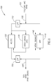
- Fig. 1 illustrates a block diagram for a novel external power unit 100 for a powerline STB, constructed and operative in accordance with a preferred embodiment of the present invention.
- Power unit 100 may comprise an AC/DC converter unit 120 and a zero cross isolation unit 130.
- Single pair input wiring 105 may carry standard 110/240 VAC voltage 101 (including HPAV signals) from the electric mains.
- Single pair output wiring 105' may provide the STB (not shown) with HPAV signals 140 along with modulated DC voltage that may, as will be hereinbelow described, be used by the STB to emulate AC zero detection.
- the depiction of wirings 105 and 105' as single pair wires may be exemplary.
- the present invention may also include embodiments wherein one or both of wirings 105 and 105' may be implemented with three wire schemes for phase, neutral and ground.
- signals on wiring 105 may pass through low pass filter 110 and high pass filter 115.
- Low pass filter 110 may filter out higher frequencies, while high pass filter 115 may filter out lower frequencies.
- the signals that successfully pass through low pass filter 110 may be fed to AC/DC converter unit 120 and zero cross detection unit 130.
- Zero cross detection unit 130 may comprise an opto coupler that may produce a 50Hz AC cycle to be fed to the AC/DC converter unit 120.
- the signal may be fed to an adjustable shunt in the power adaptor.
- the DC power output by unit 120 may be modulated by the input zero cross signal to emulate the AC phases as may be defined by the AC zero crossing.
- the modulated DC signals may then pass through low pass filter 150 to remove any residual high frequency signal.
- HPAV signals 140 may pass through high pass filter 115.
- the signals passing through filters 150 and 115 may then be carried together on a single pair wiring 105' to the STB.
- unit 100 may also be configured to return HPAV signals 140 from the STB to the electric mains. Unlike the DC power and zero crossing indications that may flow only towards the STB, HPAV signals 140 may be assumed to be bi-directional, i.e. moving in both directions. Accordingly, HPAV signals 140 may also flow from the STB via wiring 105' through HPF 115, and out to the source of VAC 101 via wiring 105. It will further be appreciated that the designation of such signals as "HPAV" may be exemplary; the present invention may be sufficiently robust to include any powerline based signal.
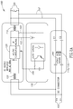
- Fig 2A illustrates an exemplary wiring diagram for the embodiment of Fig. 1 ; like numerals may refer to similar elements in both figures.
- Single pair wiring 105 may carry AC current from the electric mains.
- Single pair wiring 102 may be split off from wiring 105 to provide input for high pass filter 115. It will be appreciated that it may not be necessary to implement HPF 115 and 155 separately; a single high pass filter may be used to provide the required functionality as discussed hereinabove in the context of Fig. 1 .
- single pair wiring 103 may be split off for input to zero cross isolation unit 130.
- the low frequency AC current from unit 130 may be input to converter 120 via single pair wiring 104 to provide modulated DC current.
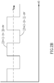
- V 0 may represent zero voltage and Vnom may represent the nominal voltage without modulation, as defined by [(V + )-V - )].
- ⁇ V may represent the contribution of the modulation to the nominal voltage. Accordingly, the modulated voltage may alternate between (Vnom + ⁇ V) and (Vnom - ⁇ V), instead of a generally stable, Vnom.
- Fig. 3 illustrates a preferred exemplary input filters architecture for external unit 100.
- the powerline port may represent wiring 105 from Fig. 1 and may be assumed to comprise 110-240VAC and HPAV signals.
- the electrical requirements for this port may be as shown in Fig. 4 , to which reference is now also made.
- Fig. 5 illustrates a preferred exemplary output filter architecture for external unit 100.
- the internal line port may represent wiring 105' from Fig. 1 and may be assumed to comprise VDC, HPAV signals & Zero Cross indications.
- the electrical requirements for the output filter of external unit 100 may be as shown in Fig. 6 , to which reference is now also made.
- Capacitors in front of the HPAV signal in transceiver 140 may be safety capacitors.
- the Zero Cross Opto coupler and HPAV transformers may pass an electrical strength test of 3KV AC and 4.242 VDC and may be UL approved.
- all components (common mode, inductors, transformers, capacitors, etc.) on the primary side may be UL approved.
- a minimum of 6.4mm creepage and 4.4mm clearance may be recommended between Primary (High Voltage Area) to Secondary Circuit (Low Voltage Area).
- the HPAV transformer maybe designed properly to be a safety transformer and UL approved. It will be appreciated that the DC voltage out of the external power unit may require readjustment to reflect the updated DC circuit mechanism and/or to supply the proper value into the Embedded Unit.
- FIG. 7 illustrates a block diagram for a novel embedded unit 200, constructed and operative in accordance with a preferred embodiment of the present invention.
- Unit 200 may comprise main embedded unit 250 to provide STB functionality.
- Unit 200 may also comprise DC/DC power supply 220 and zero cross extractor 230.
- HPAV signals 240 may be received from unit 100 via wiring 105'. It will be appreciated that the implementation of unit 200 providing STB functionality may be exemplary.
- the present invention may also include unit 200 providing other relevant functionality, such as, for example, a residential gateway (RG).
- RG residential gateway
- input from wiring 105' may be filtered by low pass filter 210 and high pass filter 215.
- Low frequency signals passing through low pass filter 210 may continue to DC/DC power supply 220 and zero crossing extractor 230.
- Power supply 220 may be any suitable power supply capable of providing DC current as required to power main embedded unit 250.
- DC/DC power supply may convert the incoming power current to 12 volts.
- Extractor 230 may extract zero cross timing information from the input AC current and forward it to main embedded unit 250 where it may be used for synchronizing the timing of the HPAV network.
- Signals 240 passing through high frequency filter 215 may be forwarded from a transceiver interface unit to main embedded unit 250.
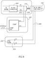
- Fig 8 illustrates an exemplary wiring diagram for the embodiment of Fig. 7 ; like numerals may refer to similar elements in both figures.
- Single pair wiring 105' may provide input from unit 100.
- Single pair wiring 202 may split off from wiring 105' to provide input to unit 215.
- High frequency HPAV signals 240 may proceed to unit 250 (not shown) via high pass filter 215.
- Signals from wiring 105' may also pass through low frequency filter 210.
- Single pair wiring 203 may split off from wiring 105' to provide low frequency AC input to zero cross detection unit 230.
- Unit 230 may compare the input IN+ and IN-signals to output a demodulated 50HZ signal suitable for zero cross processing.
- Fig. 9 illustrates a preferred exemplary input filters architecture for embedded unit 200.
- 105' may represent the wiring interface with system 100 and may be assumed to comprise VDC, HPAV signal and Zero Cross signals.
- the electrical requirements for input filters of embedded unit 200 may be as shown in Fig. 10 , to which reference is now also made.
- An AC/DC converter typically includes a low pass filter (large capacitor) to filter out residual AC signals.
- this filter may be implemented as part of the STB, instead of in the AC/DC converter.
- for the AC/DC converter may substantially include a full wave rectification such that the zero crossing information may be embedded in its output signals.
- FIG. 11 illustrates a block diagram for a novel triple wire external power unit for a powerline STB 300, constructed and operative in accordance with a preferred embodiment of the present invention.
- Power unit 300 may comprise an AC/DC converter unit 320 and a zero cross isolation unit 330.
- Single pair wiring input 105 may carry standard 110/240 VAC voltage (including HPAV- signals) from the electric mains.
- Triple wire output wiring 305' may provide the STB (not shown) with HPAV signals 340 along with modulated DC voltage that may, as will be hereinbelow described, be used by the STB to emulate AC zero detection.
- Fig 12 illustrates an exemplary wiring diagram for the embodiment of Fig. 11 ; like numerals may refer to similar elements in both figures.
- single pair wiring 105 may carry AC current from the electric mains.
- Single pair wiring 302 may be split off from wiring 105 to provide input for high pass filter 315, resulting in HPAV signals 340.
- single pair wiring 303 may be split off for input to zero cross isolation unit 330.
- the output from converter 320 may pass through low pass filter 350 to reject common mode signals relative to ground before merging with the HPAV signals 340 output from filter 315 to produce single pair wiring 306.
- Fig. 1 illustrates an exemplary wiring diagram for the embodiment of Fig. 11 ; like numerals may refer to similar elements in both figures.
- single pair wiring 105 may carry AC current from the electric mains.
- Single pair wiring 302 may be split off from wiring 105 to provide input for high pass filter 315, resulting in HPAV signals 340.
- single pair wiring 303 may be split off for input to zero cross isolation
- the low frequency AC current from unit 330 may not be input to converter 320. Instead, the extension of single wire 304 may be wrapped together with single pair 306 to produce triple wire output wiring 305'. It will be appreciated that the use of single pair wiring 105 as input to unit 300 may be exemplary; as will be further discussed hereinbelow, the present invention may also be implemented to accommodate triple wire input as well.
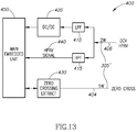
- Fig. 13 illustrates a block diagram for a novel embedded unit 400 to communicate with unit 300, constructed and operative in accordance with a preferred embodiment of the present invention.
- unit 400 may comprise main embedded unit 450 to provide STB functionality.
- Unit 400 may also comprise DC/DC power supply 420 and zero cross extractor 430. It will be appreciated that the implementation of unit 400 providing STB functionality may be exemplary.
- the present invention may also include unit 400 providing other relevant functionality, such as, for example, an HPAV network adapter.
- wiring 305' may branch into single pair wiring 406 and single wire 404.
- Single pair wiring 406 may be connected to single pair wiring 306 carrying low frequency DC and high frequency HPAV signals as described hereinabove.
- Wiring 406 may branch by passing through low pass filter 410 and high pass filter 415.
- Low frequency signals passing through low pass filter 410 may continue to DC/DC power supply 420.
- Power supply 420 may provide DC current as required to power main embedded unit 450.
- HPAV- signals 440 passing through high frequency filter 415 may be forwarded to main embedded unit 450.
- single wire 404 may be assumed to have low frequency AC signals for zero cross detection. Accordingly it may be passed directly to unit 450 via unit 430 without passing through a filter.
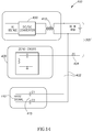
- Fig 14 illustrates an exemplary wiring diagram for the embodiment of Fig. 13 ; like numerals may refer to similar elements in both figures.
- Triple wire wiring 305' may provide input from an external power supply. It will be appreciated that wiring 305' may comprise single pair wiring 406 with DC/AC HPAV signals and single wire 404 with standard AC signals suitable for zero cross detection. Single pair wiring 402 may split off from wiring 406 to provide input to high pass filter 415; allowing high frequency HPAV signals 440 to proceed to unit 450 (not shown).
- Signals from wiring 406 may also pass through low frequency filter 410.
- single wire 404 may provide input directly to zero cross detection unit 430 without passing through a filter.
- Unit 430 may process the input signal as necessary two provide input to main embedded unit 450 (not shown).
- a disadvantage of HPAV networks may be that they are subject to ongoing interference from electrical appliances and the like that may share the powerline medium.
- three prong input from the powerline may also be leveraged to provide redundant data streams to facilitate error recovery in such a noisy environment.
- Fig. 15A illustrates a block diagram for a novel triple wire input power unit for a powerline STB 500, constructed and operative in accordance with a preferred embodiment of the present invention.
- Power unit 500 may be similar to power unit 100 as depicted in Fig. 1 , comprising an AC/DC converter unit 120 and low pass filters 110 and 150, and zero cross unit 130. However, power unit 500 may comprise two high pass filters 115. Triple wire input wiring 505 may carry standard 110/240 VAC voltage (including HPAV signals) from the electric mains. The phase and neutral wires may be paired and processed in a similar manner as in system 100 to produce output wiring 105'. However, a neutral/ground pairing may be branched off of wiring 505 and input to the second HPF 515 without further processing. Accordingly, system 500 may interface with an STB via wiring 105' as per the embodiment of Fig. 1 , but may also communicate with the STB via wiring 505'. Accordingly, system 500 may be capable of providing additional and/or redundant HPAV signals when compared to system 100.
- Fig. 15B also illustrates a block diagram for a novel triple wire input power unit for a powerline STB 500, constructed and operative in accordance with a preferred embodiment of the present invention.
- the embodiment of Fig. 15B may be generally similar to that of Fig. 15A . However, instead of adding wiring 505' to wiring 105' to interface with the STB, wiring 305' as detailed in the embodiment of Fig. 11 may be used. Accordingly, the embodiment of Fig. 15B may differ from that of Fig. 15A in that it may provide zero cross indications to the STB on a dedicated wire.
- Fig 16 illustrates an exemplary wiring diagram for the embodiment of Fig. 15B ; like numerals may refer to similar elements in both figures.
- Triple prong input wiring 505 may carry AC current from the electric mains.
- a phase neutral pairing of wires may be processed in generally the same manner as in system 300 to produce wiring 305', wherein one wire may be dedicated to carrying zero cross indications.
- the neutral and ground wires may be branched in a second pairing and input to a second HPF 315, yielding HPAV signals 340 which may be output on wiring 505' in addition to the signals on wiring 305'.
- system 500 may provide redundant and/or additional HPAV signals when compared with the previous embodiments.
- an exemplary wiring diagram for embodiment of Fig. 15A may be generally similar to that of Fig. 16 .
- phase/neutral and neutral/ground pairings may be exemplary; the present invention may include any of the possible combinations for pairing ground, neutral and phase wires. It will further be appreciated that as in the previous embodiments, the HPAV signals transmitted by system may be bidirectional, moving towards and away from the STB.
- Fig. 17 illustrates a block diagram for a novel embedded unit 600 to communicate with the embodiment of Fig. 15A , constructed and operative in accordance with a preferred embodiment of the present invention.
- unit 600 may comprise main embedded unit 250 to provide STB functionality.
- Unit 600 may also comprise DC/DC power supply 220 and zero cross extractor 230. It will be appreciated that the implementation of unit 600 providing STB functionality may be exemplary.
- the present invention may also include unit 600 providing other relevant functionality, such as, for example, an HPAV network adapter.
- input wiring 105' may carry DC, HPAV signals and zero crossing information which may be filtered by LPF 210 and HPF 215 prior to further processing as disclosed in previous embodiments 200 and 400.
- unit 250 may also receive HPAV signals directly via wiring 505'. It will be appreciated that as the signals on wiring 505' may already have passed through a high pass filter in system 500, there may be no need for further filtering in system 600.
- unit 600 may be configured in accordance with the configuration of unit 500. Accordingly, unit 600 may also be configured in a generally similar manner to unit 400 in order to accommodate processing zero cross indications on a dedicated wire if system 500 maybe configured in accordance with the embodiment of Fig. 15B .
- unit 250 may comprise redundancy reconciliation unit 655 to reconcile discrepancies between redundant HPAV signals that may be received via wiring 105' and 505'.
- unit 650 may both receive and transmit HPAV signals 340. Accordingly, as in the previous embodiments, HPAV signals 340 may be transmitted bidirectionally along wiring 105' and 505'.
- the filters architecture and electrical requirements of disclosed for the single pair wiring embodiments in Figs. 3 - 6 , 9 and 10 may be generally the same for the three prong wire embodiments. However, it may be highly recommended to use either a shielded wire or twisted wire for the Zero Cross dedicated wire.
- Phase/Neutral and Neutral/Ground pairs for the HPAV/G.hn signals. It will be appreciated, however, that Phase/Ground may also be used. In fact, as discussed hereinabove, any possible pairing may be used.
- the present invention may be applicable for any technology that communicates over power wires, such as HPAV and its flavors, HD-PLC, UPA, Smart grid related technologies, G.hn, etc.
- units 100, 200, 300, 400, 500 and 600 as configured in the hereinabove disclosed embodiments may be exemplary.
- the present invention may also include other possible configurations for the placement of some or all of the described functionality in an external power unit, the STB and/or a third unit.
- Embodiments of the present invention may include apparatus for performing the operations herein.
- This apparatus may be specially constructed for the desired purposes, or it may comprise a general-purpose computer selectively activated or reconfigured by a computer program stored in the computer.
- a computer program may be stored in a computer readable storage medium, such as, but not limited to, any type of disk, including floppy disks, optical disks, magnetic-optical disks, read-only memories (ROMs), compact disc read-only memories (CD-ROMs), random access memories (RAMs), electrically programmable read-only memories (EPROMs), electrically erasable and programmable read only memories (EEPROMs), magnetic or optical cards, Flash memory, or any other type of media suitable for storing electronic instructions and capable of being coupled to a computer system bus.
- ROMs read-only memories
- CD-ROMs compact disc read-only memories
- RAMs random access memories
- EPROMs electrically programmable read-only memories
- EEPROMs electrically erasable and
Landscapes
- Engineering & Computer Science (AREA)
- Power Engineering (AREA)
- Computer Networks & Wireless Communication (AREA)
- Signal Processing (AREA)
- Cable Transmission Systems, Equalization Of Radio And Reduction Of Echo (AREA)
- Dc Digital Transmission (AREA)
Description
- The present invention relates to power supply units generally and to their use for powerline network devices in particular.
- Residential gateways or set top boxes (STBs) that are used to configure and manage data communications networks often have external power units, where the power supply or at least one or more of its components is located in an external unit. Such external units typically comprise a plug-in adapter (or AC adapter) used to convert the alternating current (AC) electricity received from the mains to the direct current (DC) electricity used to power the adapters.
- Locating this functionality in an external unit provides a number of advantages, such as: reducing heat build-up in the STB, reducing the size of the STB, and enabling the separate configuration and/or certification of the external power unit as necessary for compliance with specific power supply requirements and regulations without having to reconfigure the main unit.
- However, external power supplies are somewhat problematic for HPAV network STBs. Such networks can be configured to transmit data over an existing powerline infrastructure typically found in a home or small office. Accordingly, in such networks the data is transmitted over the same medium as the power to run the STB. The external power unit must therefore be configured to provide both DC voltage to the STB and pass HPAV data on a high frequency AC signal (1.7 - 30 MHZ).
-
PCT Application Publication WO 2007/016031 , assigned to the common assignees of the present invention, discloses a method for using powerline phases to synchronize the scheduling of data transmission on a powerline network. As disclosed in PCT Application HPAV network STB also requires low frequency AC input from which powerline phases can be determined. - Therefore, in order to operate, an HPAV STB requires three types of electrical input: DC voltage to operate the unit itself, very low frequency (50-60Hz) AC voltage to enable zero crossing detection on the mains outlet AC cycle, and high frequency (1.7 - 30MHZ) for the HPAV/G.hn data signal.
-
US Patent Application Publication No. 2007/0195823 A1 to Biegert "describes communication of information between a network interface device and subscriber devices over a power line. A UPS unit receives operating power from subscriber premises via a first power line and delivers operating power to the network interface device via a second power line. The network interface device transmits and receives information, such as voice, video and data, to and from the UPS unit via the second power line. The UPS unit receives the information transmitted by the network interface device via the second power line, and transmits the received information to subscriber devices within the premises via the first power line. The UPS unit receives information transmitted by subscriber devices via the first power line, and transmits the received information to the network interface device via the second power line. The first and second power lines each serve as both a power line and a communication medium". - There is provided, in accordance with a preferred embodiment of the present invention, a power unit for use with a powerline communication device comprising:an AC/DC converter to at least convert VAC input to DC; a zero cross unit for generating a zero-crossing signal which is input to said AC/DC converter to modulate output from said AC/DC converter according to zero crossings in said VAC input; and at least one high pass filter (HPF) to filter said VAC input and to pass powerline data signals received on a same medium from which said VAC input is received, said at least one HPF connected in parallel to said AC/DC converter; wherein an output signal from the power unit to the powerline communication device is a combination of said modulated output from said AC/DC converter and said powerline data signals passed through said HPF.
- Further, in accordance with a preferred embodiment of the present invention, there is provided a power unit for use with a powerline communication device comprising:an AC/DC converter to at least convert VAC input to DC; a zero cross unit to detect zero crossings in said VAC input; and at least one high pass filter (HPF) to filter said VAC input and to pass powerline data signals received on a same medium from which said VAC input is received, said at least one HPF connected in parallel to said AC/DC converter; a single pair wiring to output an output signal to the powerline communication device, said output signal a combination of said DC from said AC/DC convener and said powerline data signals passed through said HPF; and a third wire to output an indicator signal associated with said detected zero crossings to the powerline communication device, said third wire suitable to be wrapped together with said single pair in a triple wire interface. The corresponding methods and further embodiments are defined in the appended claims.
- The subject matter regarded as the invention is particularly pointed out and distinctly claimed in the concluding portion of the specification. The invention, however, both as to organization and method of operation, together with objects, features, and advantages thereof, may best be understood by reference to the following detailed description when read with the accompanying drawings in which:
-
Fig. 1 is a schematic illustration of a novel power unit, constructed and operative in accordance with a preferred embodiment of the present invention; -
Fig. 2A is a schematic illustration of an exemplary electrical wiring diagram for the power unit ofFig. 1 ; -
Fig. 2B is a schematic illustration of an exemplary representation of modulated DC voltage as may be produced by the system ofFigs 1 and2A ; -
Figs. 3 and5 are schematic illustrations of preferred exemplary input and output filters architectures for the power unit ofFig. 1 ; -
Figs. 4 and6 are tables of electrical requirements for the architectures ofFig 3 and5 , respectively; -
Fig. 7 is a schematic illustration of a novel embedded power unit to communicate with the power unit ofFig. 1 ; -
Fig. 8 is a schematic illustration of an exemplary electrical wiring diagram for the power unit ofFig. 7 ; -
Fig. 9 is a schematic illustration of a preferred exemplary input filter architectures for the power unit ofFig. 7 ; -
Fig. 10 is a tables of electrical requirements for the architectures ofFig 9 ; -
Fig. 11 is a schematic illustration of a novel triple wire interface power unit, constructed and operative in accordance with a preferred embodiment of the present invention; -
Fig. 12 is a schematic illustration of an exemplary electrical wiring diagram for the power unit ofFig. 11 ; -
Fig. 13 is a schematic illustration of a novel embedded power unit to communicate with the power unit ofFig. 11 ; -
Fig. 14 is a schematic illustration of an exemplary electrical wiring diagram for the power unit ofFig. 13 ; -
Figs. 15 are schematic illustrations of novel triple prong power units, constructed and operative in accordance with preferred embodiments of the present invention; -
Fig. 16 is a schematic illustration of an exemplary electrical wiring diagram for the power unit ofFig. 15B ; and -
Fig. 17 is a schematic illustration of a novel embedded power unit to communicate with the power unit ofFig. 15B . - It will be appreciated that for simplicity and clarity of illustration, elements shown in the figures have not necessarily been drawn to scale. For example, the dimensions of some of the elements may be exaggerated relative to other elements for clarity. Further, where considered appropriate, reference numerals may be repeated among the figures to indicate corresponding or analogous elements.
- In the following detailed description, numerous specific details are set forth in order to provide a thorough understanding of the invention. However, it will be understood by those skilled in the art that the present invention may be practiced without these specific details. In other instances, well-known methods, procedures, and components have not been described in detail so as not to obscure the present invention.
- Reference is now made to
Fig. 1 which illustrates a block diagram for a novelexternal power unit 100 for a powerline STB, constructed and operative in accordance with a preferred embodiment of the present invention.Power unit 100 may comprise an AC/DC converter unit 120 and a zerocross isolation unit 130. Singlepair input wiring 105 may carry standard 110/240 VAC voltage 101 (including HPAV signals) from the electric mains. Single pair output wiring 105' may provide the STB (not shown) withHPAV signals 140 along with modulated DC voltage that may, as will be hereinbelow described, be used by the STB to emulate AC zero detection. It will be appreciated that the depiction ofwirings 105 and 105' as single pair wires may be exemplary. As will be discussed hereinbelow, the present invention may also include embodiments wherein one or both ofwirings 105 and 105' may be implemented with three wire schemes for phase, neutral and ground. - In operation, signals on
wiring 105 may pass throughlow pass filter 110 andhigh pass filter 115.Low pass filter 110 may filter out higher frequencies, whilehigh pass filter 115 may filter out lower frequencies. The signals that successfully pass throughlow pass filter 110 may be fed to AC/DC converter unit 120 and zerocross detection unit 130. - Zero
cross detection unit 130 may comprise an opto coupler that may produce a 50Hz AC cycle to be fed to the AC/DC converter unit 120. The signal may be fed to an adjustable shunt in the power adaptor. In such manner, the DC power output byunit 120 may be modulated by the input zero cross signal to emulate the AC phases as may be defined by the AC zero crossing. The modulated DC signals may then pass throughlow pass filter 150 to remove any residual high frequency signal. - HPAV signals 140 may pass through
high pass filter 115. The signals passing throughfilters - It will be appreciated that
unit 100 may also be configured to return HPAV signals 140 from the STB to the electric mains. Unlike the DC power and zero crossing indications that may flow only towards the STB, HPAV signals 140 may be assumed to be bi-directional, i.e. moving in both directions. Accordingly, HPAV signals 140 may also flow from the STB via wiring 105' throughHPF 115, and out to the source ofVAC 101 viawiring 105. It will further be appreciated that the designation of such signals as "HPAV" may be exemplary; the present invention may be sufficiently robust to include any powerline based signal. -
Fig 2A , to which reference is now made, illustrates an exemplary wiring diagram for the embodiment ofFig. 1 ; like numerals may refer to similar elements in both figures.Single pair wiring 105 may carry AC current from the electric mains.Single pair wiring 102 may be split off from wiring 105 to provide input forhigh pass filter 115. It will be appreciated that it may not be necessary to implementHPF 115 and 155 separately; a single high pass filter may be used to provide the required functionality as discussed hereinabove in the context ofFig. 1 . After the AC current passes throughlow pass filter 110,single pair wiring 103 may be split off for input to zerocross isolation unit 130. The low frequency AC current fromunit 130 may be input toconverter 120 viasingle pair wiring 104 to provide modulated DC current.Fig. 2B , to which reference is now briefly made, illustrates an exemplary representation of DC voltage as may be produced bysystem 100. V0 may represent zero voltage and Vnom may represent the nominal voltage without modulation, as defined by [(V+)-V-)]. ΔV may represent the contribution of the modulation to the nominal voltage. Accordingly, the modulated voltage may alternate between (Vnom + ΔV) and (Vnom - ΔV), instead of a generally stable, Vnom. - Reference is now made to
Fig. 3 which illustrates a preferred exemplary input filters architecture forexternal unit 100. The powerline port may represent wiring 105 fromFig. 1 and may be assumed to comprise 110-240VAC and HPAV signals. The electrical requirements for this port may be as shown inFig. 4 , to which reference is now also made. - Reference is also made to
Fig. 5 which illustrates a preferred exemplary output filter architecture forexternal unit 100. The internal line port may represent wiring 105' fromFig. 1 and may be assumed to comprise VDC, HPAV signals & Zero Cross indications. The electrical requirements for the output filter ofexternal unit 100 may be as shown inFig. 6 , to which reference is now also made. - In accordance with a preferred exemplary embodiment of the present invention, the following guidelines may be followed for implementing unit 100: Capacitors in front of the HPAV signal in
transceiver 140 may be safety capacitors. The Zero Cross Opto coupler and HPAV transformers may pass an electrical strength test of 3KV AC and 4.242 VDC and may be UL approved. Preferably, all components (common mode, inductors, transformers, capacitors, etc.) on the primary side may be UL approved. A
minimum of 6.4mm creepage and 4.4mm clearance may be recommended between Primary (High Voltage Area) to Secondary Circuit (Low Voltage Area). The HPAV transformer maybe designed properly to be a safety transformer and UL approved. It will be appreciated that the DC voltage out of the external power unit may require readjustment to reflect the updated DC circuit mechanism and/or to supply the proper value into the Embedded Unit. - An embedded unit may be added to the STB itself to communicate with
unit 100.Fig. 7 , to which reference is now made, illustrates a block diagram for a novel embeddedunit 200, constructed and operative in accordance with a preferred embodiment of the present invention.Unit 200 may comprise main embeddedunit 250 to provide STB functionality.Unit 200 may also comprise DC/DC power supply 220 and zerocross extractor 230. HPAV signals 240 may be received fromunit 100 via wiring 105'. It will be appreciated that the implementation ofunit 200 providing STB functionality may be exemplary. The present invention may also includeunit 200 providing other relevant functionality, such as, for example, a residential gateway (RG). - In operation, input from wiring 105' may be filtered by
low pass filter 210 andhigh pass filter 215. Low frequency signals passing throughlow pass filter 210 may continue to DC/DC power supply 220 and zerocrossing extractor 230.Power supply 220 may be any suitable power supply capable of providing DC current as required to power main embeddedunit 250. For example, DC/DC power supply may convert the incoming power current to 12 volts.Extractor 230 may extract zero cross timing information from the input AC current and forward it to main embeddedunit 250 where it may be used for synchronizing the timing of the HPAV network.Signals 240 passing throughhigh frequency filter 215 may be forwarded from a transceiver interface unit to main embeddedunit 250. -
Fig 8 , to which reference is now made, illustrates an exemplary wiring diagram for the embodiment ofFig. 7 ; like numerals may refer to similar elements in both figures. Single pair wiring 105' may provide input fromunit 100.Single pair wiring 202 may split off from wiring 105' to provide input tounit 215. High frequency HPAV signals 240 may proceed to unit 250 (not shown) viahigh pass filter 215. - Signals from wiring 105' may also pass through
low frequency filter 210.Single pair wiring 203 may split off from wiring 105' to provide low frequency AC input to zerocross detection unit 230.Unit 230 may compare the input IN+ and IN-signals to output a demodulated 50HZ signal suitable for zero cross processing. - Reference is now made to
Fig. 9 which illustrates a preferred exemplary input filters architecture for embeddedunit 200. 105' may represent the wiring interface withsystem 100 and may be assumed to comprise VDC, HPAV signal and Zero Cross signals. The electrical requirements for input filters of embeddedunit 200 may be as shown inFig. 10 , to which reference is now also made. - Applicants have also realized that an alternate solution for zero cross indication may be implemented without modulating the DC signals. An AC/DC converter typically includes a low pass filter (large capacitor) to filter out residual AC signals. In accordance with a preferred embodiment of the present invention, this filter may be implemented as part of the STB, instead of in the AC/DC converter. In such an embodiment, for the AC/DC converter may substantially include a full wave rectification such that the zero crossing information may be embedded in its output signals.
- Applicants further realize that the connection from the external power unit to the STB may be via a three wire interface.
Fig. 11 , to which reference is now made, illustrates a block diagram for a novel triple wire external power unit for apowerline STB 300, constructed and operative in accordance with a preferred embodiment of the present invention.Power unit 300 may comprise an AC/DC converter unit 320 and a zerocross isolation unit 330. Singlepair wiring input 105 may carry standard 110/240 VAC voltage (including HPAV- signals) from the electric mains. Triple wire output wiring 305' may provide the STB (not shown) withHPAV signals 340 along with modulated DC voltage that may, as will be hereinbelow described, be used by the STB to emulate AC zero detection. -
Fig 12 , to which reference is now made, illustrates an exemplary wiring diagram for the embodiment ofFig. 11 ; like numerals may refer to similar elements in both figures. Similar to the embodiment ofFig. 2 ,single pair wiring 105 may carry AC current from the electric mains.Single pair wiring 302 may be split off from wiring 105 to provide input forhigh pass filter 315, resulting in HPAV signals 340. After the AC current passes throughlow pass filter 310,single pair wiring 303 may be split off for input to zerocross isolation unit 330. The output fromconverter 320 may pass throughlow pass filter 350 to reject common mode signals relative to ground before merging with the HPAV signals 340 output fromfilter 315 to producesingle pair wiring 306. Unlike the embodiment ofFig. 2A , the low frequency AC current fromunit 330 may not be input toconverter 320. Instead, the extension ofsingle wire 304 may be wrapped together withsingle pair 306 to produce triple wire output wiring 305'. It will be appreciated that the use ofsingle pair wiring 105 as input tounit 300 may be exemplary; as will be further discussed hereinbelow, the present invention may also be implemented to accommodate triple wire input as well. -
Fig. 13 , to which reference is now made, illustrates a block diagram for a novel embeddedunit 400 to communicate withunit 300, constructed and operative in accordance with a preferred embodiment of the present invention. Similar tounit 200,unit 400 may comprise main embeddedunit 450 to provide STB functionality.Unit 400 may also comprise DC/DC power supply 420 and zerocross extractor 430. It will be appreciated that the implementation ofunit 400 providing STB functionality may be exemplary. The present invention may also includeunit 400 providing other relevant functionality, such as, for example, an HPAV network adapter. - In operation, wiring 305' may branch into
single pair wiring 406 andsingle wire 404.Single pair wiring 406 may be connected tosingle pair wiring 306 carrying low frequency DC and high frequency HPAV signals as described hereinabove. Wiring 406 may branch by passing throughlow pass filter 410 andhigh pass filter 415. Low frequency signals passing throughlow pass filter 410 may continue to DC/DC power supply 420.Power supply 420 may provide DC current as required to power main embeddedunit 450. HPAV-signals 440 passing throughhigh frequency filter 415 may be forwarded to main embeddedunit 450. Unlike the embodiment ofFig. 3 ,single wire 404 may be assumed to have low frequency AC signals for zero cross detection. Accordingly it may be passed directly tounit 450 viaunit 430 without passing through a filter. -
Fig 14 , to which reference is now made, illustrates an exemplary wiring diagram for the embodiment ofFig. 13 ; like numerals may refer to similar elements in both figures. Triple wire wiring 305'may provide input from an external power supply. It will be appreciated that wiring 305' may comprisesingle pair wiring 406 with DC/AC HPAV signals andsingle wire 404 with standard AC signals suitable for zero cross detection.Single pair wiring 402 may split off from wiring 406 to provide input tohigh pass filter 415; allowing high frequency HPAV signals 440 to proceed to unit 450 (not shown). - Signals from
wiring 406 may also pass throughlow frequency filter 410. Unlike the embodiment ofFig. 8 ,single wire 404 may provide input directly to zerocross detection unit 430 without passing through a filter.Unit 430 may process the input signal as necessary two provide input to main embedded unit 450 (not shown). - It will be appreciated that a disadvantage of HPAV networks may be that they are subject to ongoing interference from electrical appliances and the like that may share the powerline medium. In accordance with a preferred embodiment of the present invention, three prong input from the powerline may also be leveraged to provide redundant data streams to facilitate error recovery in such a noisy environment. Reference is now made to
Fig. 15A which illustrates a block diagram for a novel triple wire input power unit for apowerline STB 500, constructed and operative in accordance with a preferred embodiment of the present invention. -
Power unit 500 may be similar topower unit 100 as depicted inFig. 1 , comprising an AC/DC converter unit 120 and low pass filters 110 and 150, and zerocross unit 130. However,power unit 500 may comprise two high pass filters 115. Triplewire input wiring 505 may carry standard 110/240 VAC voltage (including HPAV signals) from the electric mains. The phase and neutral wires may be paired and processed in a similar manner as insystem 100 to produce output wiring 105'. However, a neutral/ground pairing may be branched off ofwiring 505 and input to the second HPF 515 without further processing. Accordingly,system 500 may interface with an STB via wiring 105' as per the embodiment ofFig. 1 , but may also communicate with the STB via wiring 505'. Accordingly,system 500 may be capable of providing additional and/or redundant HPAV signals when compared tosystem 100. - Reference is now made also to
Fig. 15B which also illustrates a block diagram for a novel triple wire input power unit for apowerline STB 500, constructed and operative in accordance with a preferred embodiment of the present invention. The embodiment ofFig. 15B may be generally similar to that ofFig. 15A . However, instead of adding wiring 505' to wiring 105' to interface with the STB, wiring 305' as detailed in the embodiment ofFig. 11 may be used. Accordingly, the embodiment ofFig. 15B may differ from that ofFig. 15A in that it may provide zero cross indications to the STB on a dedicated wire. -
Fig 16 , to which reference is now made, illustrates an exemplary wiring diagram for the embodiment ofFig. 15B ; like numerals may refer to similar elements in both figures. Tripleprong input wiring 505 may carry AC current from the electric mains. In accordance with a preferred embodiment of the present invention, a phase neutral pairing of wires may be processed in generally the same manner as insystem 300 to produce wiring 305', wherein one wire may be dedicated to carrying zero cross indications. In accordance with a preferred embodiment of the present invention, the neutral and ground wires may be branched in a second pairing and input to asecond HPF 315, yielding HPAV signals 340 which may be output on wiring 505' in addition to the signals on wiring 305'. In such manner,system 500 may provide redundant and/or additional HPAV signals when compared with the previous embodiments. - It will be appreciated that with the exception of the provision of a dedicated line for zero cross indications, an exemplary wiring diagram for embodiment of
Fig. 15A may be generally similar to that ofFig. 16 . - It will also be appreciated that the disclosure of phase/neutral and neutral/ground pairings may be exemplary; the present invention may include any of the possible combinations for pairing ground, neutral and phase wires. It will further be appreciated that as in the previous embodiments, the HPAV signals transmitted by system may be bidirectional, moving towards and away from the STB.
-
Fig. 17 , to which reference is now made, illustrates a block diagram for a novel embeddedunit 600 to communicate with the embodiment ofFig. 15A , constructed and operative in accordance with a preferred embodiment of the present invention. Similar tounits unit 600 may comprise main embeddedunit 250 to provide STB functionality.Unit 600 may also comprise DC/DC power supply 220 and zerocross extractor 230. It will be appreciated that the implementation ofunit 600 providing STB functionality may be exemplary. The present invention may also includeunit 600 providing other relevant functionality, such as, for example, an HPAV network adapter. - Similar to
system 200, input wiring 105' may carry DC, HPAV signals and zero crossing information which may be filtered byLPF 210 andHPF 215 prior to further processing as disclosed inprevious embodiments system 200,unit 250 may also receive HPAV signals directly via wiring 505'. It will be appreciated that as the signals on wiring 505' may already have passed through a high pass filter insystem 500, there may be no need for further filtering insystem 600. - It will be appreciated that
unit 600 may be configured in accordance with the configuration ofunit 500. Accordingly,unit 600 may also be configured in a generally similar manner tounit 400 in order to accommodate processing zero cross indications on a dedicated wire ifsystem 500 maybe configured in accordance with the embodiment ofFig. 15B . - In accordance with a preferred embodiment of the present invention,
unit 250 may compriseredundancy reconciliation unit 655 to reconcile discrepancies between redundant HPAV signals that may be received via wiring 105' and 505'. - It will be appreciated that unit 650 may both receive and transmit HPAV signals 340. Accordingly, as in the previous embodiments, HPAV signals 340 may be transmitted bidirectionally along wiring 105' and 505'.
- It will also be appreciated that the filters architecture and electrical requirements of disclosed for the single pair wiring embodiments in
Figs. 3 - 6 ,9 and 10 may be generally the same for the three prong wire embodiments. However, it may be highly recommended to use either a shielded wire or twisted wire for the Zero Cross dedicated wire. - When implementing the triple wire embodiments as disclosed hereinabove, in order to increase throughput speed it may be preferable to use Phase/Neutral and Neutral/Ground pairs for the HPAV/G.hn signals. It will be appreciated, however, that Phase/Ground may also be used. In fact, as discussed hereinabove, any possible pairing may be used.
- It will be appreciated that the present invention may be applicable for any technology that communicates over power wires, such as HPAV and its flavors, HD-PLC, UPA, Smart grid related technologies, G.hn, etc.
- It will also be appreciated that
units - Unless specifically stated otherwise, as apparent from the preceding discussions, it is appreciated that, throughout the specification, discussions utilizing terms such as "processing," "computing," "calculating," "determining," or the like, refer to the action and/or processes of a computer, computing system, or similar electronic computing device that manipulates and/or transforms data represented as physical, such as electronic, quantities within the computing system's registers and/or memories into other data similarly represented as physical quantities within the computing system's memories, registers or other such information storage, transmission or display devices.
- Embodiments of the present invention may include apparatus for performing the operations herein. This apparatus may be specially constructed for the desired purposes, or it may comprise a general-purpose computer selectively activated or reconfigured by a computer program stored in the computer. Such a computer program may be stored in a computer readable storage medium, such as, but not limited to, any type of disk, including floppy disks, optical disks, magnetic-optical disks, read-only memories (ROMs), compact disc read-only memories (CD-ROMs), random access memories (RAMs), electrically programmable read-only memories (EPROMs), electrically erasable and programmable read only memories (EEPROMs), magnetic or optical cards, Flash memory, or any other type of media suitable for storing electronic instructions and capable of being coupled to a computer system bus.
- The processes and displays presented herein are not inherently related to any particular computer or other apparatus. Various general-purpose systems may be used with programs in accordance with the teachings herein, or it may prove convenient to construct a more specialized apparatus to perform the desired method. The desired structure for a variety of these systems will appear from the description below. In addition, embodiments of the present invention are not described with reference to any particular programming language. It will be appreciated that a variety of programming languages may be used to implement the teachings of the invention as described herein.
- While certain features of the invention have been illustrated and described herein, many modifications, substitutions, changes, and equivalents will now occur to those of ordinary skill in the art. It is, therefore, to be understood that the invention is not limited to the particular embodiments described herein, but is capable of many rearrangements, modifications, and substitutions without departing from the scope of the invention.
Claims (20)
- A power unit (100) for use with a powerline communication device comprising:an AC/DC converter (120) to at least convert VAC input (101) to DC;a zero cross unit (130) for generating a zero-crossing signal which is input to said AC/DC converter (120) to modulate output from said AC/DC converter according to zero crossings in said VAC input; andat least one high pass filter, HPF, (115) to filter said VAC input and to pass powerline data signals (140) received on a same medium from which said VAC input is received, said at least one HPF connected in parallel to said AC/DC converter;wherein an output signal from the power unit to the powerline communication device is a combination of said modulated output from said AC/DC converter and said powerline data signals passed through said HPF.
- The power unit (100) according to claim 1 and wherein said power unit is housed in an external unit connectable to an embedded unit (250) capable of processing said data signals.
- The power unit (100) according to claim 2 and wherein said embedded unit (250) is at least one of a set top box (STB) and a gateway.
- The power unit (100) according to claim 1 and wherein:at least one of said AC/DC converter (120), said zero cross unit (130) and said high pass filter (115) are housed in a device comprising means for processing said data signals; andat least one of said AC/DC converter, said zero cross unit and said high pass filter are located external to said device.
- The power unit (100) according to claim 1 and wherein said data signals (140) are one of HPAV and G.hn signals.
- The power unit (100) according to claim 1 and also comprising at least one low pass filter (110) to facilitate input of low frequency AC signals to at least one of said AC/DC converter (120) and said zero cross unit (130).
- The power unit (500) according to claim 1 and also comprising:a triple wire input (505) to receive said VAC input and said powerline data signals, wherein a first combination of two wires of said triple wire input are branched to provide input to said AC/DC converter (120) and said at least one HPF (115); a second HPF (115) to filter said VAC input and to pass said powerline data signals (140) received from a second combination of two wires branched from said triple wire input;a first single pair wiring (105) to output said output signal to the powerline communication device; anda second single pair wiring (505) to output at least said passed powerline data signals (140) from said second HPF (115) to the powerline communication device.
- A power unit (300) for use with a powerline communication device comprising:an AC/DC converter (320) to at least convert VAC input (101) to DC;a zero cross unit (330) to detect zero crossings in said VAC input; andat least one high pass filter, HPF, (315) to filter said VAC input and to pass powerline data signals (340) received on a same medium from which said VAC input is received, said at least one HPF connected in parallel to said AC/DC converter;a single pair wiring (306) to output an output signal to the powerline communication device, said output signal a combination of said DC from said AC/DC converter and said powerline data signals passed through said HPF; anda third wire (304) to output an indicator signal associated with said detected zero crossings to the powerline communication device, said third wire suitable to be wrapped together with said single pair in a triple wire interface (305).
- The power unit (500) according to claim 8 and also comprising:a triple wire input (505) to receive said VAC input (101) and said powerline data signals, wherein a first combination of two wires of said triple wire input are branched to provide input to said AC/DC converter (120) and said at least one HPF (115);a second HPF (115) to filter said VAC input and to pass said powerline data signals (140) received from a second combination of two wires branched from said triple wire input; anda second single pair wiring (505) to output at least said passed powerline data signals (140) from said second HPF (115) to the powerline communication device.
- The power unit (300) according to claim 8 and wherein the power unit is housed in an external unit connectable to an embedded unit (250) capable of processing said data signals.
- The power unit (300) according to claim 9 and wherein said embedded unit (250) is at least one of a set top box, STB, and a gateway.
- The power unit (300) according to claim 8 and wherein:at least one of said AC/DC converter (320), said zero cross unit (330) and said at least high pass filter (315) are housed in a device (250) comprising means for processing said data signals; andat least one of said AC/DC converter (320), said zero cross unit (330) and said high pass filter (315) are located external to said device (250).
- The power unit according to claim 8 and wherein said data signals (340) are one of HPAV and G.hn signals.
- The power unit (300) according to claim 8 and also comprising at least one low pass filter (310) to facilitate input of low frequency AC signals to at least one of said AC/DC converter (320) and said zero cross unit (330).
- A method for providing power and data signals from a single powerline source, the method comprising:receiving incoming VAC (101) in an external power unit (100);converting said incoming VAC to DC with an AC/DC converter (120);modulating said DC by said AC/DC converter (120) responsive to a zero-crossing signal input to said AC/DC converter, said zero-crossing signal associated_with zero crossings from said incoming VAC (101);filtering said incoming VAC (101) to at least isolate powerline data signals (140), wherein said powerline data signals are received on a same medium from which said incoming VAC is received;combining said modulated DC and said powerline data signals in an output signal; andproviding said output signal to an embedded processing unit (250) capable of processing said powerline data signals.
- The method according to claim 15 and wherein at least one of said converting, said modulating and said filtering is performed in an external power unit (100).
- The method according to claim 15 and wherein at least one of said converting, said modulating and said filtering is performed in said processing unit (250).
- A method for providing power and data signals from a single powerline source, the method comprising:receiving incoming VAC (101) in an external power unit (300);converting said incoming VAC to DC;filtering said incoming VAC (101) to at least isolate powerline data signals (340), wherein said powerline data signals (340) are received on a same medium from which said incoming VAC is received;detecting zero crossings in said incoming VAC;combining said DC and said received powerline data signals in an output signal for transmitting over a single pair wiring (306);outputting an indicator signal associated with said detected zero crossings in a third wire (304) suitable to be wrapped together with said single pair wire in a triple wire interface (305); andproviding said output signal and said indicator signal to an embedded processing unit (250) capable of processing said powerline data signals.
- The method according to claim 18 and wherein at least one of said converting, said modulating and said filtering is performed in an external power unit (300).
- The method according to claim 18 and wherein at least one of said converting, said modulating and said filtering is performed in said processing unit (250).
Applications Claiming Priority (2)
| Application Number | Priority Date | Filing Date | Title |
|---|---|---|---|
| US26711209P | 2009-12-07 | 2009-12-07 | |
| PCT/IB2010/055639 WO2011070512A2 (en) | 2009-12-07 | 2010-12-07 | Enhanced power supply unit for powerline networks |
Publications (3)
| Publication Number | Publication Date |
|---|---|
| EP2510608A2 EP2510608A2 (en) | 2012-10-17 |
| EP2510608A4 EP2510608A4 (en) | 2014-09-24 |
| EP2510608B1 true EP2510608B1 (en) | 2016-03-02 |
Family
ID=44145983
Family Applications (1)
| Application Number | Title | Priority Date | Filing Date |
|---|---|---|---|
| EP10835579.3A Active EP2510608B1 (en) | 2009-12-07 | 2010-12-07 | Enhanced power supply unit for powerline networks |
Country Status (3)
| Country | Link |
|---|---|
| US (1) | US8823499B2 (en) |
| EP (1) | EP2510608B1 (en) |
| WO (1) | WO2011070512A2 (en) |
Families Citing this family (7)
| Publication number | Priority date | Publication date | Assignee | Title |
|---|---|---|---|---|
| JP5498347B2 (en) * | 2010-10-20 | 2014-05-21 | 株式会社メガチップス | PLC / power hybrid device and device with communication function |
| JP5900944B2 (en) * | 2010-11-22 | 2016-04-06 | ソニー株式会社 | Power relay terminal, power relay method, power supply control device, power supply control method, and power supply control system |
| JP5780120B2 (en) * | 2011-11-02 | 2015-09-16 | ブラザー工業株式会社 | Power supply system, image forming apparatus equipped with the power supply system, and small-capacity power supply circuit |
| JP6056475B2 (en) | 2012-12-28 | 2017-01-11 | ブラザー工業株式会社 | Power supply system and image forming apparatus equipped with the power supply system |
| US9787360B2 (en) | 2013-01-28 | 2017-10-10 | Sigma Designs Israel S.D.I. Ltd. | Zero crossing indicator device |
| US9722729B2 (en) | 2013-05-31 | 2017-08-01 | Qualcomm Incorporated | Extracting zero cross information in a powerline communication device |
| KR102333914B1 (en) * | 2019-08-16 | 2021-12-13 | 최창준 | Power Line Communication with Polarity switching |
Family Cites Families (15)
| Publication number | Priority date | Publication date | Assignee | Title |
|---|---|---|---|---|
| US5416416A (en) | 1992-02-24 | 1995-05-16 | Bisher; Roger C. | Method and apparatus for testing an auxiliary power system |
| US6377163B1 (en) * | 2000-09-21 | 2002-04-23 | Home Touch Lighting Systems Llc | Power line communication circuit |
| US6842668B2 (en) * | 2001-09-06 | 2005-01-11 | Genlyte Thomas Group Llc | Remotely accessible power controller for building lighting |
| WO2003044924A1 (en) * | 2001-11-22 | 2003-05-30 | Doo Won Precision Co., Ltd. | Control system for suppling power by power line communication |
| US20060291575A1 (en) | 2003-07-03 | 2006-12-28 | Berkman William H | Power Line Communication System and Method |
| US20050049754A1 (en) * | 2003-08-29 | 2005-03-03 | Craig Ogawa | Power and data configurations for building automation systems |
| US8228924B2 (en) * | 2005-05-26 | 2012-07-24 | Sony Corporation | AC PLC to DC PLC transceiver |
| US7366817B2 (en) * | 2005-06-29 | 2008-04-29 | Intel Corporation | Frame order processing apparatus, systems, and methods |
| US8553706B2 (en) | 2005-07-27 | 2013-10-08 | Coppergate Communications Ltd. | Flexible scheduling of resources in a noisy environment |
| US7417535B2 (en) * | 2005-09-02 | 2008-08-26 | Radioshack Corporation | Apparatus and method for converting a low voltage AC wiring circuit to a high speed data communications link |
| JP4849972B2 (en) * | 2005-09-15 | 2012-01-11 | パナソニック株式会社 | Communication device, communication system, image acquisition device, moving image acquisition device, and setting method thereof |
| US8115606B2 (en) * | 2005-10-18 | 2012-02-14 | Computime, Ltd. | Matching a transmitter and a receiver supplied by the same power module |
| US7923855B2 (en) * | 2006-02-17 | 2011-04-12 | Calix, Inc. | Communication between network interface device and subscriber devices via power supply lines |
| US7456588B2 (en) * | 2006-06-05 | 2008-11-25 | Osram Sylvania Inc. | Arrangement and method for providing power line communication from an AC power source to a circuit for powering a load, and electronic ballasts therefor |
| US20080316004A1 (en) * | 2007-06-19 | 2008-12-25 | Kiko Frederick J | Powerline communication apparatus and methods |
-
2010
- 2010-12-07 EP EP10835579.3A patent/EP2510608B1/en active Active
- 2010-12-07 WO PCT/IB2010/055639 patent/WO2011070512A2/en not_active Ceased
- 2010-12-07 US US12/962,187 patent/US8823499B2/en active Active
Also Published As
| Publication number | Publication date |
|---|---|
| US20110175712A1 (en) | 2011-07-21 |
| US8823499B2 (en) | 2014-09-02 |
| EP2510608A2 (en) | 2012-10-17 |
| EP2510608A4 (en) | 2014-09-24 |
| WO2011070512A2 (en) | 2011-06-16 |
| WO2011070512A3 (en) | 2011-08-11 |
Similar Documents
| Publication | Publication Date | Title |
|---|---|---|
| US8823499B2 (en) | Enhanced power supply unit for powerline networks | |
| US10374813B2 (en) | Coupler for power line communication and power-over-ethernet | |
| US7245212B2 (en) | Power line communication apparatus and method of using the same | |
| US20050001694A1 (en) | Power line communication system and method of operating the same | |
| US10056943B2 (en) | System for transmitting and receiving a power line communication signal over the power bus of a power electronic converter | |
| US8149106B2 (en) | Apparatus and method for data communication over power lines | |
| EP2720380A2 (en) | Power line communication (PLC) coupling through an external power supply | |
| DK2484019T3 (en) | A method for data transmission from a transmitter to a receiver in a device for AC voltage and AC voltage to the data transfer | |
| US9520832B2 (en) | Device for connecting two pieces of equipment via an Ethernet link, and a docking station for such a piece of equipment | |
| CN108112273B (en) | Fuel gauge and adapter module for it | |
| US9059783B2 (en) | Electronic device with a carrier current | |
| EP2869475B1 (en) | Transformer for power line communication | |
| Ahmed et al. | Power line carrier (PLC) based communication system for distribution automation system | |
| JP2002124897A (en) | Communication system and communication method | |
| KR101454263B1 (en) | Power Line Communication Line Structure and Construction Method | |
| WO2007010083A1 (en) | Apparatus for arranging data transfer | |
| US20120007422A1 (en) | System and Method for Passing PLC Signals from a First Electrical Line to a Second Electrical Line |
Legal Events
| Date | Code | Title | Description |
|---|---|---|---|
| PUAI | Public reference made under article 153(3) epc to a published international application that has entered the european phase |
Free format text: ORIGINAL CODE: 0009012 |
|
| 17P | Request for examination filed |
Effective date: 20120628 |
|
| AK | Designated contracting states |
Kind code of ref document: A2 Designated state(s): AL AT BE BG CH CY CZ DE DK EE ES FI FR GB GR HR HU IE IS IT LI LT LU LV MC MK MT NL NO PL PT RO RS SE SI SK SM TR |
|
| DAX | Request for extension of the european patent (deleted) | ||
| REG | Reference to a national code |
Ref country code: DE Ref legal event code: R079 Ref document number: 602010030987 Country of ref document: DE Free format text: PREVIOUS MAIN CLASS: H02M0007000000 Ipc: H04B0003560000 |
|
| A4 | Supplementary search report drawn up and despatched |
Effective date: 20140826 |
|
| RIC1 | Information provided on ipc code assigned before grant |
Ipc: H04B 3/56 20060101AFI20140820BHEP Ipc: H04B 3/54 20060101ALI20140820BHEP |
|
| GRAP | Despatch of communication of intention to grant a patent |
Free format text: ORIGINAL CODE: EPIDOSNIGR1 |
|
| INTG | Intention to grant announced |
Effective date: 20150717 |
|
| GRAS | Grant fee paid |
Free format text: ORIGINAL CODE: EPIDOSNIGR3 |
|
| INTG | Intention to grant announced |
Effective date: 20151209 |
|
| GRAA | (expected) grant |
Free format text: ORIGINAL CODE: 0009210 |
|
| AK | Designated contracting states |
Kind code of ref document: B1 Designated state(s): AL AT BE BG CH CY CZ DE DK EE ES FI FR GB GR HR HU IE IS IT LI LT LU LV MC MK MT NL NO PL PT RO RS SE SI SK SM TR |
|
| REG | Reference to a national code |
Ref country code: GB Ref legal event code: FG4D |
|
| REG | Reference to a national code |
Ref country code: AT Ref legal event code: REF Ref document number: 778627 Country of ref document: AT Kind code of ref document: T Effective date: 20160315 Ref country code: CH Ref legal event code: EP |
|
| REG | Reference to a national code |
Ref country code: IE Ref legal event code: FG4D |
|
| REG | Reference to a national code |
Ref country code: DE Ref legal event code: R096 Ref document number: 602010030987 Country of ref document: DE |
|
| REG | Reference to a national code |
Ref country code: NL Ref legal event code: FP |
|
| REG | Reference to a national code |
Ref country code: LT Ref legal event code: MG4D |
|
| REG | Reference to a national code |
Ref country code: AT Ref legal event code: MK05 Ref document number: 778627 Country of ref document: AT Kind code of ref document: T Effective date: 20160302 |
|
| PG25 | Lapsed in a contracting state [announced via postgrant information from national office to epo] |
Ref country code: FI Free format text: LAPSE BECAUSE OF FAILURE TO SUBMIT A TRANSLATION OF THE DESCRIPTION OR TO PAY THE FEE WITHIN THE PRESCRIBED TIME-LIMIT Effective date: 20160302 Ref country code: GR Free format text: LAPSE BECAUSE OF FAILURE TO SUBMIT A TRANSLATION OF THE DESCRIPTION OR TO PAY THE FEE WITHIN THE PRESCRIBED TIME-LIMIT Effective date: 20160603 Ref country code: HR Free format text: LAPSE BECAUSE OF FAILURE TO SUBMIT A TRANSLATION OF THE DESCRIPTION OR TO PAY THE FEE WITHIN THE PRESCRIBED TIME-LIMIT Effective date: 20160302 Ref country code: ES Free format text: LAPSE BECAUSE OF FAILURE TO SUBMIT A TRANSLATION OF THE DESCRIPTION OR TO PAY THE FEE WITHIN THE PRESCRIBED TIME-LIMIT Effective date: 20160302 Ref country code: NO Free format text: LAPSE BECAUSE OF FAILURE TO SUBMIT A TRANSLATION OF THE DESCRIPTION OR TO PAY THE FEE WITHIN THE PRESCRIBED TIME-LIMIT Effective date: 20160602 |
|
| PG25 | Lapsed in a contracting state [announced via postgrant information from national office to epo] |
Ref country code: AT Free format text: LAPSE BECAUSE OF FAILURE TO SUBMIT A TRANSLATION OF THE DESCRIPTION OR TO PAY THE FEE WITHIN THE PRESCRIBED TIME-LIMIT Effective date: 20160302 Ref country code: PL Free format text: LAPSE BECAUSE OF FAILURE TO SUBMIT A TRANSLATION OF THE DESCRIPTION OR TO PAY THE FEE WITHIN THE PRESCRIBED TIME-LIMIT Effective date: 20160302 Ref country code: RS Free format text: LAPSE BECAUSE OF FAILURE TO SUBMIT A TRANSLATION OF THE DESCRIPTION OR TO PAY THE FEE WITHIN THE PRESCRIBED TIME-LIMIT Effective date: 20160302 Ref country code: LV Free format text: LAPSE BECAUSE OF FAILURE TO SUBMIT A TRANSLATION OF THE DESCRIPTION OR TO PAY THE FEE WITHIN THE PRESCRIBED TIME-LIMIT Effective date: 20160302 Ref country code: LT Free format text: LAPSE BECAUSE OF FAILURE TO SUBMIT A TRANSLATION OF THE DESCRIPTION OR TO PAY THE FEE WITHIN THE PRESCRIBED TIME-LIMIT Effective date: 20160302 Ref country code: SE Free format text: LAPSE BECAUSE OF FAILURE TO SUBMIT A TRANSLATION OF THE DESCRIPTION OR TO PAY THE FEE WITHIN THE PRESCRIBED TIME-LIMIT Effective date: 20160302 |
|
| PG25 | Lapsed in a contracting state [announced via postgrant information from national office to epo] |
Ref country code: EE Free format text: LAPSE BECAUSE OF FAILURE TO SUBMIT A TRANSLATION OF THE DESCRIPTION OR TO PAY THE FEE WITHIN THE PRESCRIBED TIME-LIMIT Effective date: 20160302 Ref country code: IS Free format text: LAPSE BECAUSE OF FAILURE TO SUBMIT A TRANSLATION OF THE DESCRIPTION OR TO PAY THE FEE WITHIN THE PRESCRIBED TIME-LIMIT Effective date: 20160702 |
|
| PG25 | Lapsed in a contracting state [announced via postgrant information from national office to epo] |
Ref country code: CZ Free format text: LAPSE BECAUSE OF FAILURE TO SUBMIT A TRANSLATION OF THE DESCRIPTION OR TO PAY THE FEE WITHIN THE PRESCRIBED TIME-LIMIT Effective date: 20160302 Ref country code: RO Free format text: LAPSE BECAUSE OF FAILURE TO SUBMIT A TRANSLATION OF THE DESCRIPTION OR TO PAY THE FEE WITHIN THE PRESCRIBED TIME-LIMIT Effective date: 20160302 Ref country code: PT Free format text: LAPSE BECAUSE OF FAILURE TO SUBMIT A TRANSLATION OF THE DESCRIPTION OR TO PAY THE FEE WITHIN THE PRESCRIBED TIME-LIMIT Effective date: 20160704 Ref country code: SK Free format text: LAPSE BECAUSE OF FAILURE TO SUBMIT A TRANSLATION OF THE DESCRIPTION OR TO PAY THE FEE WITHIN THE PRESCRIBED TIME-LIMIT Effective date: 20160302 Ref country code: SM Free format text: LAPSE BECAUSE OF FAILURE TO SUBMIT A TRANSLATION OF THE DESCRIPTION OR TO PAY THE FEE WITHIN THE PRESCRIBED TIME-LIMIT Effective date: 20160302 |
|
| REG | Reference to a national code |
Ref country code: DE Ref legal event code: R097 Ref document number: 602010030987 Country of ref document: DE |
|
| PG25 | Lapsed in a contracting state [announced via postgrant information from national office to epo] |
Ref country code: BE Free format text: LAPSE BECAUSE OF FAILURE TO SUBMIT A TRANSLATION OF THE DESCRIPTION OR TO PAY THE FEE WITHIN THE PRESCRIBED TIME-LIMIT Effective date: 20160302 Ref country code: IT Free format text: LAPSE BECAUSE OF FAILURE TO SUBMIT A TRANSLATION OF THE DESCRIPTION OR TO PAY THE FEE WITHIN THE PRESCRIBED TIME-LIMIT Effective date: 20160302 |
|
| PLBE | No opposition filed within time limit |
Free format text: ORIGINAL CODE: 0009261 |
|
| STAA | Information on the status of an ep patent application or granted ep patent |
Free format text: STATUS: NO OPPOSITION FILED WITHIN TIME LIMIT |
|
| PG25 | Lapsed in a contracting state [announced via postgrant information from national office to epo] |
Ref country code: DK Free format text: LAPSE BECAUSE OF FAILURE TO SUBMIT A TRANSLATION OF THE DESCRIPTION OR TO PAY THE FEE WITHIN THE PRESCRIBED TIME-LIMIT Effective date: 20160302 |
|
| 26N | No opposition filed |
Effective date: 20161205 |
|
| PG25 | Lapsed in a contracting state [announced via postgrant information from national office to epo] |
Ref country code: BG Free format text: LAPSE BECAUSE OF FAILURE TO SUBMIT A TRANSLATION OF THE DESCRIPTION OR TO PAY THE FEE WITHIN THE PRESCRIBED TIME-LIMIT Effective date: 20160602 Ref country code: SI Free format text: LAPSE BECAUSE OF FAILURE TO SUBMIT A TRANSLATION OF THE DESCRIPTION OR TO PAY THE FEE WITHIN THE PRESCRIBED TIME-LIMIT Effective date: 20160302 |
|
| REG | Reference to a national code |
Ref country code: DE Ref legal event code: R119 Ref document number: 602010030987 Country of ref document: DE |
|
| REG | Reference to a national code |
Ref country code: CH Ref legal event code: PL |
|
| PG25 | Lapsed in a contracting state [announced via postgrant information from national office to epo] |
Ref country code: MC Free format text: LAPSE BECAUSE OF FAILURE TO SUBMIT A TRANSLATION OF THE DESCRIPTION OR TO PAY THE FEE WITHIN THE PRESCRIBED TIME-LIMIT Effective date: 20160302 |
|
| REG | Reference to a national code |
Ref country code: FR Ref legal event code: ST Effective date: 20170831 |
|
| REG | Reference to a national code |
Ref country code: IE Ref legal event code: MM4A |
|
| PG25 | Lapsed in a contracting state [announced via postgrant information from national office to epo] |
Ref country code: LU Free format text: LAPSE BECAUSE OF NON-PAYMENT OF DUE FEES Effective date: 20161207 Ref country code: LI Free format text: LAPSE BECAUSE OF NON-PAYMENT OF DUE FEES Effective date: 20161231 Ref country code: CH Free format text: LAPSE BECAUSE OF NON-PAYMENT OF DUE FEES Effective date: 20161231 Ref country code: FR Free format text: LAPSE BECAUSE OF NON-PAYMENT OF DUE FEES Effective date: 20170102 |
|
| PG25 | Lapsed in a contracting state [announced via postgrant information from national office to epo] |
Ref country code: DE Free format text: LAPSE BECAUSE OF NON-PAYMENT OF DUE FEES Effective date: 20170701 Ref country code: IE Free format text: LAPSE BECAUSE OF NON-PAYMENT OF DUE FEES Effective date: 20161207 |
|
| PG25 | Lapsed in a contracting state [announced via postgrant information from national office to epo] |
Ref country code: HU Free format text: LAPSE BECAUSE OF FAILURE TO SUBMIT A TRANSLATION OF THE DESCRIPTION OR TO PAY THE FEE WITHIN THE PRESCRIBED TIME-LIMIT; INVALID AB INITIO Effective date: 20101207 Ref country code: CY Free format text: LAPSE BECAUSE OF FAILURE TO SUBMIT A TRANSLATION OF THE DESCRIPTION OR TO PAY THE FEE WITHIN THE PRESCRIBED TIME-LIMIT Effective date: 20160302 |
|
| PG25 | Lapsed in a contracting state [announced via postgrant information from national office to epo] |
Ref country code: MK Free format text: LAPSE BECAUSE OF FAILURE TO SUBMIT A TRANSLATION OF THE DESCRIPTION OR TO PAY THE FEE WITHIN THE PRESCRIBED TIME-LIMIT Effective date: 20160302 Ref country code: TR Free format text: LAPSE BECAUSE OF FAILURE TO SUBMIT A TRANSLATION OF THE DESCRIPTION OR TO PAY THE FEE WITHIN THE PRESCRIBED TIME-LIMIT Effective date: 20160302 |
|
| PG25 | Lapsed in a contracting state [announced via postgrant information from national office to epo] |
Ref country code: MT Free format text: LAPSE BECAUSE OF NON-PAYMENT OF DUE FEES Effective date: 20161207 |
|
| PG25 | Lapsed in a contracting state [announced via postgrant information from national office to epo] |
Ref country code: AL Free format text: LAPSE BECAUSE OF FAILURE TO SUBMIT A TRANSLATION OF THE DESCRIPTION OR TO PAY THE FEE WITHIN THE PRESCRIBED TIME-LIMIT Effective date: 20160302 |
|
| PGFP | Annual fee paid to national office [announced via postgrant information from national office to epo] |
Ref country code: NL Payment date: 20251006 Year of fee payment: 16 |
|
| PGFP | Annual fee paid to national office [announced via postgrant information from national office to epo] |
Ref country code: GB Payment date: 20251001 Year of fee payment: 16 |