EP2510202B1 - A regulator - Google Patents
A regulator Download PDFInfo
- Publication number
- EP2510202B1 EP2510202B1 EP10782358.5A EP10782358A EP2510202B1 EP 2510202 B1 EP2510202 B1 EP 2510202B1 EP 10782358 A EP10782358 A EP 10782358A EP 2510202 B1 EP2510202 B1 EP 2510202B1
- Authority
- EP
- European Patent Office
- Prior art keywords
- diaphragm
- gas
- regulator
- chamber
- coupled
- Prior art date
- Legal status (The legal status is an assumption and is not a legal conclusion. Google has not performed a legal analysis and makes no representation as to the accuracy of the status listed.)
- Active
Links
- 239000007789 gas Substances 0.000 claims description 61
- 238000009423 ventilation Methods 0.000 claims description 15
- 239000000356 contaminant Substances 0.000 claims description 8
- 230000004044 response Effects 0.000 claims description 8
- 230000004888 barrier function Effects 0.000 claims description 7
- 230000008859 change Effects 0.000 claims description 7
- 239000007788 liquid Substances 0.000 claims description 4
- 239000007787 solid Substances 0.000 claims description 2
- 238000001914 filtration Methods 0.000 description 4
- 239000000443 aerosol Substances 0.000 description 3
- 238000002485 combustion reaction Methods 0.000 description 3
- 238000006073 displacement reaction Methods 0.000 description 3
- 230000000694 effects Effects 0.000 description 3
- 230000009467 reduction Effects 0.000 description 3
- 230000001105 regulatory effect Effects 0.000 description 3
- CURLTUGMZLYLDI-UHFFFAOYSA-N Carbon dioxide Chemical compound O=C=O CURLTUGMZLYLDI-UHFFFAOYSA-N 0.000 description 2
- 230000008901 benefit Effects 0.000 description 2
- 230000001276 controlling effect Effects 0.000 description 2
- 239000012530 fluid Substances 0.000 description 2
- 229930195733 hydrocarbon Natural products 0.000 description 2
- 150000002430 hydrocarbons Chemical class 0.000 description 2
- 239000004071 soot Substances 0.000 description 2
- UGFAIRIUMAVXCW-UHFFFAOYSA-N Carbon monoxide Chemical compound [O+]#[C-] UGFAIRIUMAVXCW-UHFFFAOYSA-N 0.000 description 1
- GQPLMRYTRLFLPF-UHFFFAOYSA-N Nitrous Oxide Chemical class [O-][N+]#N GQPLMRYTRLFLPF-UHFFFAOYSA-N 0.000 description 1
- 150000001299 aldehydes Chemical class 0.000 description 1
- QVGXLLKOCUKJST-UHFFFAOYSA-N atomic oxygen Chemical compound [O] QVGXLLKOCUKJST-UHFFFAOYSA-N 0.000 description 1
- 239000006227 byproduct Substances 0.000 description 1
- 229910002092 carbon dioxide Inorganic materials 0.000 description 1
- 239000001569 carbon dioxide Substances 0.000 description 1
- 229910002091 carbon monoxide Inorganic materials 0.000 description 1
- 239000000567 combustion gas Substances 0.000 description 1
- 230000001419 dependent effect Effects 0.000 description 1
- 230000007613 environmental effect Effects 0.000 description 1
- VUZPPFZMUPKLLV-UHFFFAOYSA-N methane;hydrate Chemical compound C.O VUZPPFZMUPKLLV-UHFFFAOYSA-N 0.000 description 1
- 239000000203 mixture Substances 0.000 description 1
- 229910052760 oxygen Inorganic materials 0.000 description 1
- 239000001301 oxygen Substances 0.000 description 1
- 239000002245 particle Substances 0.000 description 1
- 230000000717 retained effect Effects 0.000 description 1
- 238000005096 rolling process Methods 0.000 description 1
- 238000000926 separation method Methods 0.000 description 1
- 230000003584 silencer Effects 0.000 description 1
- 238000013022 venting Methods 0.000 description 1
- XLYOFNOQVPJJNP-UHFFFAOYSA-N water Substances O XLYOFNOQVPJJNP-UHFFFAOYSA-N 0.000 description 1
- 229910001868 water Inorganic materials 0.000 description 1
Images


Classifications
-
- F—MECHANICAL ENGINEERING; LIGHTING; HEATING; WEAPONS; BLASTING
- F01—MACHINES OR ENGINES IN GENERAL; ENGINE PLANTS IN GENERAL; STEAM ENGINES
- F01M—LUBRICATING OF MACHINES OR ENGINES IN GENERAL; LUBRICATING INTERNAL COMBUSTION ENGINES; CRANKCASE VENTILATING
- F01M13/00—Crankcase ventilating or breathing
- F01M13/02—Crankcase ventilating or breathing by means of additional source of positive or negative pressure
- F01M13/021—Crankcase ventilating or breathing by means of additional source of positive or negative pressure of negative pressure
- F01M13/022—Crankcase ventilating or breathing by means of additional source of positive or negative pressure of negative pressure using engine inlet suction
- F01M13/023—Control valves in suction conduit
-
- F—MECHANICAL ENGINEERING; LIGHTING; HEATING; WEAPONS; BLASTING
- F01—MACHINES OR ENGINES IN GENERAL; ENGINE PLANTS IN GENERAL; STEAM ENGINES
- F01M—LUBRICATING OF MACHINES OR ENGINES IN GENERAL; LUBRICATING INTERNAL COMBUSTION ENGINES; CRANKCASE VENTILATING
- F01M13/00—Crankcase ventilating or breathing
- F01M13/04—Crankcase ventilating or breathing having means for purifying air before leaving crankcase, e.g. removing oil
-
- F—MECHANICAL ENGINEERING; LIGHTING; HEATING; WEAPONS; BLASTING
- F01—MACHINES OR ENGINES IN GENERAL; ENGINE PLANTS IN GENERAL; STEAM ENGINES
- F01M—LUBRICATING OF MACHINES OR ENGINES IN GENERAL; LUBRICATING INTERNAL COMBUSTION ENGINES; CRANKCASE VENTILATING
- F01M13/00—Crankcase ventilating or breathing
- F01M13/0011—Breather valves
- F01M2013/0016—Breather valves with a membrane
-
- F—MECHANICAL ENGINEERING; LIGHTING; HEATING; WEAPONS; BLASTING
- F01—MACHINES OR ENGINES IN GENERAL; ENGINE PLANTS IN GENERAL; STEAM ENGINES
- F01M—LUBRICATING OF MACHINES OR ENGINES IN GENERAL; LUBRICATING INTERNAL COMBUSTION ENGINES; CRANKCASE VENTILATING
- F01M13/00—Crankcase ventilating or breathing
- F01M13/02—Crankcase ventilating or breathing by means of additional source of positive or negative pressure
- F01M13/021—Crankcase ventilating or breathing by means of additional source of positive or negative pressure of negative pressure
- F01M2013/026—Crankcase ventilating or breathing by means of additional source of positive or negative pressure of negative pressure with pumps sucking air or blow-by gases from the crankcase
-
- Y—GENERAL TAGGING OF NEW TECHNOLOGICAL DEVELOPMENTS; GENERAL TAGGING OF CROSS-SECTIONAL TECHNOLOGIES SPANNING OVER SEVERAL SECTIONS OF THE IPC; TECHNICAL SUBJECTS COVERED BY FORMER USPC CROSS-REFERENCE ART COLLECTIONS [XRACs] AND DIGESTS
- Y10—TECHNICAL SUBJECTS COVERED BY FORMER USPC
- Y10T—TECHNICAL SUBJECTS COVERED BY FORMER US CLASSIFICATION
- Y10T137/00—Fluid handling
- Y10T137/7722—Line condition change responsive valves
- Y10T137/7781—With separate connected fluid reactor surface
- Y10T137/7793—With opening bias [e.g., pressure regulator]
-
- Y—GENERAL TAGGING OF NEW TECHNOLOGICAL DEVELOPMENTS; GENERAL TAGGING OF CROSS-SECTIONAL TECHNOLOGIES SPANNING OVER SEVERAL SECTIONS OF THE IPC; TECHNICAL SUBJECTS COVERED BY FORMER USPC CROSS-REFERENCE ART COLLECTIONS [XRACs] AND DIGESTS
- Y10—TECHNICAL SUBJECTS COVERED BY FORMER USPC
- Y10T—TECHNICAL SUBJECTS COVERED BY FORMER US CLASSIFICATION
- Y10T137/00—Fluid handling
- Y10T137/7722—Line condition change responsive valves
- Y10T137/7781—With separate connected fluid reactor surface
- Y10T137/7835—Valve seating in direction of flow
- Y10T137/7836—Flexible diaphragm or bellows reactor
Description
- The present invention relates to a regulator. In particular, the present invention relates to a regulator for regulating the pressure within a crankcase ventilation system. In particular, the present invention provides a regulator suitable for use in a pumped crankcase ventilation system. In certain embodiments of the present invention, the regulator may be used in a crankcase ventilation system further incorporating a separator for separating particulate, liquid and aerosol contaminants from a blow-by gas stream within a reciprocating engine.
- Blow-by gas within a reciprocating engine is generated as a by-product of the combustion process. During combustion, some of the mixture of gases escape past piston rings or other seals and enter the engine crankcase outside of the pistons. The term "blow-by" refers to the fact that the gas has blown past the piston seals. The flow level of blow-by gas is dependent upon several factors, for example the engine displacement, the effectiveness of the piston cylinder seals and the power output of the engine. Blow-by gas typically has the following components: oil (as both a liquid and an aerosol, with aerosol droplets in the range 0.1µm to 10µm), soot particles, nitrous oxides (NOx), hydrocarbons (both gaseous hydrocarbons and gaseous aldehydes), carbon monoxide, carbon dioxide, oxygen, water and other gaseous air components.
- If blow-by gas is retained within a crankcase with no outlet, the pressure within the crankcase rises until the pressure is relieved by leakage of crankcase oil elsewhere within the engine, for example at the crankcase seals, dipstick seals or turbocharger seals. Such a leak may result in damage to the engine.
- In order to prevent such damage, and excessive loss of oil, it is known to provide an outlet valve which allows the blow-by gas to be vented to the atmosphere. However, with increasing environmental awareness generally, and within the motor industry in particular, it is becoming increasingly unacceptable to allow blow-by gas, which is inevitably contaminated with oil and other contaminants from within the crankcase, to simply be vented to atmosphere. Furthermore, such venting increases the speed at which crankcase oil is consumed.
- Consequently, it is known to filter the blow-by gas. The filtered blow-by gas may then either be vented to the atmosphere as before (in an open loop system), or it may be returned to an air inlet of the engine (in a closed loop system). The filtering may be performed by passing the blow-by gas through a filtering medium, or another known form of gas contaminant separator. For a closed loop system, filtration is required in order to remove oil, soot and other contaminants to protect engine components from fouling and any resultant reduction in performance or failure of a component.
- The conventional arrangement of an engine blow-by gas / oil separator returning cleaned gas to an engine air intake is commonly referred to as a Closed Crankcase Ventilation system (CCV). This system requires the use of a crankcase pressure regulator in order to ensure that an excessive proportion of the vacuum generated by the engine air intake is not translated via the CCV separator to the engine crankcase.
- Referring now to
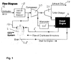
figure 1 , this illustrates the arrangement of a conventional CCV system 2 coupled to adiesel engine 4. Blow-by gas from the engine crankcase passes to the CCV system 2 along inlet duct 6. The CCV system 2 comprises aregulator 8 coupled to the inlet duct 6 and a contaminant separator 10 in series. Theregulator 8 and separator 10 are not visible infigure 1 , howeverfigure 2 is a flow chart schematically illustrating the arrangement of the components of the CCV system. - A
pump 12 may optionally be provided within the CCV system to increase the pressure drop across the separator 10, thereby increasing the filtering efficiency. Cleaned blow-by gas exits the CCV system throughgas outlet 14 and is returned to the engine air intake system. Specifically, the engine air intake system draws in air from outside of the vehicle through aninlet 16, the air then passing through an inlet air filter andsilencer 18, acompressor 20 driven by a turbo charger 22 (in turn driven by the engine exhaust 24) and an aftercooler 26 to cool the compressed air before it is supplied to theengine 4. The cleaned blow-by gas passes from thegas outlet 14 to thecompressor 20. Oil and other contaminants separated from the blow-by gas are returned to the engine crankcase throughoil drain 28. - In the system of
figures 1 and2 a portion of the vacuum generated between theturbocharger 22 and theair filter 18 is lost over the blow-by separator 10. Any remaining vacuum otherwise exposed to the engine crankcase is controlled by theregulator 8. It can be seen that the total air flow drawn by theturbo compressor 22 is not necessarily restricted by the closing of the regulator, since the difference can be drawn via theengine air filter 18. - A
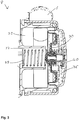
conventional regulator 8 known for use in a CCV system is illustrated infigure 3 . Theregulator 8 comprises a floatingdiaphragm 30 which is arranged to open or close to restrict blow-by gas flow and pressure as required. Blow-by gas enters afirst regulator chamber 32 through the CCV gas inlet 6. Thediaphragm 30 at least partially occludes the gap between thefirst chamber 32 and a second chamber 34 (in turn coupled to the separator 10). A first side ofdiaphragm 30 is exposed to the blow-by gas inchamber 32. A second side of thediaphragm 30 is exposed to an ambient gas pressure within achamber 36, which has an opening to the ambient environment. Alternatively, the third chamber may be coupled to a different pressure reference. - Movement of the
diaphragm 30 is controlled by first andsecond springs Spring 38 is positioned within the second chamber and resists movement of thediaphragm 30 to close the gap between the first andsecond chambers Spring 40 is positioned within thethird chamber 36 and resists movement of thediaphragm 30 to open the gap between the first andsecond chambers springs diaphragm 30 acted upon by the blow-by gas and the ambient gas pressure can be used to control the rate and extent of movement of thediaphragm 30. - The application of an
integral pump 12 to improve the separation performance of a CCV system 2 is relatively new. The pressure in thefirst chamber 32 is regulated to the desired crankcase pressure by specification of the pump to generate the required vacuum and specifying appropriate pressure regulation spring forces. The pressure in thesecond chamber 34 is defined by the differential pressure loss across the separator and the vacuum generated by theintegral pump 12. The vacuum generated is determined according to the operating point along the chosen pump's flow versus pressure performance curve. - It will be appreciated that for a pumped CCV separator system the flow through the pump can be entirely restricted by the position of the regulating diaphragm. For the regulator illustrated in
figure 3 , if thediaphragm 30 comes into contact with the end of tubular wall 42 separating the first andsecond chambers pump 12 is similar to the phenomenon of pump surge in which an unregulated displacement pump can give rise to spikes in the output pressure. Restricted flow resulting from a closed regulator moves the pump operating point to a corresponding low flow and high vacuum position. The increased vacuum generated in the second chamber further increases the force acting on thevacuum regulation springs diaphragm 30 generated by a build up of positive pressure in the engine crankcase can open the regulator again. As discussed above, excessive pressure build up in a crankcase can result in damage to the crankcase and escape of oil. A closed loop control cycle of high and low pressure hunting results between the regulator and the pump which cannot be controlled with a conventional linear response regulator. - It will be further appreciated that the problems of high and low pressure hunting for pumped CCV systems may also be experienced within other forms of crankcase ventilation systems. Specifically, pressure hunting may occur in open crankcase ventilation systems, non-pumped closed crankcase ventilation systems and exhaust pumped ventilation systems. More generally, the problems discussed above associated with conventional regulators may occur in any system which includes a pressure regulator.
-
DE-U-20016214 disclsoes a throttle valve for automatically controlling the pressure in the crankcase of an internal combustion engine. The valve has a first chamber which receives combustion gases from the engine and a second chamber from which gases are discharged from the valve. Gases pass between the first and second chambers through upper and lower coaxial tubes which have openings in their side walls. The upper tube can slide telescopically relative to the lower tube, depending on the pressure difference across a diaphragm between the first chamber and a pressure reference. The size of the flow path through the openings in the tubes varies depending on the position of the upper tube relative to the lower tube. - The present invention seeks to provide a regulator which resists the effects of pump surge and pressure hunting discussed above when the regulator is used within a pumped CCV system.
- The invention therefore provides a regulator as defined in claim 1.
- An advantage of the first aspect of the present invention is that because the rate of change of the cross sectional area of the aperture has a non-linear response to a change in the pressure differential, any desired control function can be generated. For instance, for a constant rate of change in the pressure differential, the rate of reduction of the cross sectional area of the aperture may accelerate.
- The first and second chambers may be separated by a tubular wall and the barrier may comprise a tubular structure coupled to the diaphragm and arranged to slide within or over the tubular wall to partially occlude the slot.
- The invention also provides a crankcase ventilation system as defined in claim 3.
- The crankcase ventilation system may further comprise a separator arranged to filter solid and liquid contaminants from gases passing between the gas inlet and the gas outlet.
- The crankcase ventilation system may further comprise a pump coupled between the regulator and the gas outlet and arranged to generate a vacuum thereby increasing the pressure differential across the regulator.
- An embodiment of the present invention will now be described, by way of example only, with reference to the accompanying drawings, in which:
-
Figure 1 schematically illustrates an engine system including a closed crankcase ventilation system; -
Figure 2 schematically illustrates a CCV system; -
Figure 3 illustrates a cross sectional view of a conventional regulator for use in a CCV system; and -
Figure 4 illustrates a cross sectional view of a regulator in accordance with an embodiment of the present invention for use in a CCV system. - Referring to
figure 4 , aregulator 108 in accordance with an embodiment of the present invention is illustrated. Theregulator 108 is in part similar in structure to theregulator 8 offigure 3 and so corresponding features are referred to by reference numbers that are incremented by 100. - The
regulator 108 comprises a floatingdiaphragm 130 which is arranged to open or close to restrict blow-by gas flow and pressure as required to regulate the pressure within an engine crankcase. Blow-by gas enters afirst regulator chamber 132 through theCCV gas inlet 106. Thediaphragm 130 partially occludes the gap between thefirst chamber 132 and a second chamber 134 (in turn coupled to a CCV separator and pump). A first side ofdiaphragm 130 is exposed to the blow-by gas inchamber 132. A second side of thediaphragm 130 is exposed to an ambient pressure within achamber 136, which has an opening to the ambient environment. In particular, the ambient environment may comprise a gas port extending to external of the engine, or the vehicle. More generally, thechamber 136 may be coupled to any other gas pressure reference. Movement of thediaphragm 130 is controlled by first andsecond springs Spring 138 is positioned within the second chamber and resists thediaphragm 130 moving to close the gap between the first andsecond chambers Spring 140 is positioned within thethird chamber 136 and resists movement of thediaphragm 130 to open the gap between the first andsecond chambers springs diaphragm 130 acted upon by the blow-by gas and the ambient gas pressure can be used to control the rate and extent of movement of thediaphragm 130. Thediaphragm 130 comprises an actuator arranged to control the flow of blow-by gas between the first andsecond chambers - The first and
second chambers tubular wall 150. The first side ofdiaphragm 130 is coupled to atubular structure 152 arranged to slide within thetubular wall 150, and is coupled to thefirst spring 138. The interface between thetubular wall 150 and thetubular structure 152 may be arranged to substantially prevent blow-by gas from passing between the two, or a controlled amount of blow-by gas may be allowed to flow through the gap. Movement of thediaphragm 130 according to the pressure differential between thefirst chamber 132 and thethird chamber 136 causes thetubular structure 152 to slide withintubular wall 150. - A
slot 154 is cut into thetubular wall 150. Theslot 154, in combination with thetubular structure 152 defines anopen area 156 through which blow-by gas can flow between the first andsecond chambers open area 156 forms an aperture between the first andsecond chambers slot 154 is arranged to ensure that theopen area 156 left open by the movingtubular structure 152 causes a pressure differential across theopen area 156 which is appropriate for the flow-rate and vacuum characteristics generated by the pump. By controlling the shape of slot 154 a linear or non linear relationship between any change in pump vacuum and the corresponding distance travelled by the diaphragm can be achieved. More specifically, the shape of theslot 154 can be chosen such that movement of thediaphragm 130 at a constant rate causes a non-linear response in the cross sectional area of theopen area 156. Effectively any closed loop control function can be can be generated by thediaphragm 130 in response to a given input from the pump. More accurate crankcase pressure regulation can be achieved than for conventional regulators of the form illustrated infigure 3 . - It can be seen that for the
slot 154 offigure 4 , astubular structure 152 slides further into the tubular wall 150 (to the left infigure 4 ) the rate of reduction ofopen area 156 increases for a given displacement off thediaphragm 130. This is because theslot 154 tapers towards its closed end. Movement ofdiaphragm 130 may be limited to ensure that theopen area 156 is never completely closed off. - It will be readily apparent to the appropriately skilled person that the shape of the
slot 154 may vary significantly in order to achieve the desired closed loop control function. For instance, the slot may broaden towards its closed end, be of constant width or initially taper and terminate with an enlarged portion to prevent full closure of theopen area 156. Furthermore, multiple slots of different sizes and shapes may be provided around the tubular wall. - In alternative embodiments of the invention one or more slots may be formed alternatively or additionally in the tubular structure coupled to the diaphragm. Furthermore, the tubular structure coupled to the diaphragm may be arranged to pass outside of the tubular wall separating the first and second chambers. In place of the tubular structure, a rolling portion of the diaphragm may be arranged to progressively cover and expose one or more slots in order to vary the size of the or each open area between the first and second chambers.
- In alternative embodiments of the invention the first and second chambers may be separated by walls having alternative shapes, for instance a single planar wall extending between the two chambers and including a slot as described above. The actuator may comprise a sliding barrier coupled to the diaphragm arranged to partially occlude the slot.
- More generally, the present invention is not limited to any one particular structure. Rather the scope of the appended claims should be considered to cover any regulator in which a first chamber and a second chamber are coupled together by one or more open areas. The size of the or each open area is arranged to be varied according to the position of a diaphragm or other moveable actuator which adjusts its position according to a pressure differential between gas in the first and / or second chambers and an external pressure reference.
- Regulators according to the present invention have been primarily described herein in use as part of a CCV system. However, it will be readily apparent to the appropriately skilled person that they may be more widely applicable. More generally, such a regulator may be used in any application in which it is necessary to regulate a pressure drop for a fluid between a first chamber and a second chamber, with reference to an external pressure. Typically, the fluid will be a gas. Regulators according to the present invention are of particular benefit in pumped systems in order to obviate or mitigate the effects of pump surge and pressure hunting described above in the introductory portion of this description.
Claims (5)
- A regulator (8; 108) comprising:a first chamber (132),a second chamber (134) separated from the first chamber by a wall (150) between the chambers which has one or more slots (154) formed in it,a housing containing the first and second chambers,a diaphragm (130) coupled to the housing and separating the first chamber from a pressure reference (136), anda sliding barrier (152) coupled to the diaphragm and arranged progressively to occlude the slots as the diaphragm moves, the slots and the barrier defining one or more apertures between the chambers,in which the diaphragm is arranged to move in response to a change in the differential pressure across the diaphragm to adjust the size of the apertures, the shape of the slots being such that the rate of change of the cross sectional area of the apertures varies non-linearly in response to a change in the pressure differential and to the distance travelled by the diaphragm,and in which the interface between the wall and the sliding barrier is arranged substantially to prevent blow-by gas from passing between the first and second chambers when the slots are occluded by the sliding barrier.
- A regulator according to claim 1, in which the first and second chambers (132, 134) are separated by a tubular wall (150) and the barrier comprises a tubular structure (152) coupled to the diaphragm (130) and arranged to slide within or over the tubular wall to partially occlude the slot.
- A crankcase ventilation system comprising:a gas inlet (6; 106) arranged to receive gas from a crankcase,a regulator (8; 108) according to any one of the preceding claims, in which the gas inlet (106) is coupled to the first chamber (132), anda gas outlet (14) coupled to the second chamber (134),in which the gas outlet is arranged to be coupled to an engine air inlet system or to discharge gases to the ambient environment.
- A crankcase ventilation system according to claim 3, further comprising a separator (10) arranged to filter solid and liquid contaminants from gases passing between the gas inlet (6; 106) and the gas outlet (14).
- A crankcase ventilation system according to claim 3 or claim 4, further comprising a pump (12) coupled between the regulator (8; 108) and the gas outlet (14) and arranged to generate a vacuum thereby increasing the pressure differential across the regulator.
Applications Claiming Priority (2)
| Application Number | Priority Date | Filing Date | Title |
|---|---|---|---|
| GB0921576A GB0921576D0 (en) | 2009-12-10 | 2009-12-10 | A regulator |
| PCT/GB2010/051906 WO2011070341A1 (en) | 2009-12-10 | 2010-11-16 | A regulator |
Publications (2)
| Publication Number | Publication Date |
|---|---|
| EP2510202A1 EP2510202A1 (en) | 2012-10-17 |
| EP2510202B1 true EP2510202B1 (en) | 2017-09-20 |
Family
ID=41666860
Family Applications (1)
| Application Number | Title | Priority Date | Filing Date |
|---|---|---|---|
| EP10782358.5A Active EP2510202B1 (en) | 2009-12-10 | 2010-11-16 | A regulator |
Country Status (4)
| Country | Link |
|---|---|
| US (1) | US8752578B2 (en) |
| EP (1) | EP2510202B1 (en) |
| GB (1) | GB0921576D0 (en) |
| WO (1) | WO2011070341A1 (en) |
Families Citing this family (4)
| Publication number | Priority date | Publication date | Assignee | Title |
|---|---|---|---|---|
| GB201001876D0 (en) | 2010-02-05 | 2010-03-24 | Parker Hannifin U K Ltd | A separator |
| GB201113072D0 (en) * | 2011-07-29 | 2011-09-14 | Parker Hannifin Mfg Uk Ltd | A separator |
| JP6000552B2 (en) * | 2012-01-19 | 2016-09-28 | ヤンマー株式会社 | Engine equipment |
| US8992667B2 (en) * | 2012-08-16 | 2015-03-31 | Cummins Filtration Ip, Inc. | Systems and methods for closed crankcase ventilation and air filtration |
Family Cites Families (23)
| Publication number | Priority date | Publication date | Assignee | Title |
|---|---|---|---|---|
| US3105477A (en) | 1962-01-08 | 1963-10-01 | Novo Ind Corp | Crankcase valve ventilating system |
| US3308798A (en) * | 1965-05-05 | 1967-03-14 | Kenneth M Snider | Metering valve for crankcase ventilation systems |
| US3380441A (en) * | 1965-08-23 | 1968-04-30 | Gen Motors Corp | Crankcase ventilation flow regulator valve |
| US3469565A (en) * | 1967-08-17 | 1969-09-30 | Caterpillar Tractor Co | Crankcase ventilating means for internal combustion engines |
| US3678910A (en) | 1971-03-31 | 1972-07-25 | Ford Motor Co | Control valve for positive crankcase ventilation system |
| US4245592A (en) | 1979-05-22 | 1981-01-20 | Chrysler Corporation | Controlled flow purge system and apparatus |
| US4483508A (en) * | 1982-02-22 | 1984-11-20 | Colt Industries Operating Corp | Gradient power valve assembly |
| CH664798A5 (en) * | 1983-11-14 | 1988-03-31 | Bbc Brown Boveri & Cie | DEVICE FOR RETURNING THE BLOW-OFF QUANTITY FROM THE CRANKCASE. |
| US5564401A (en) | 1995-07-21 | 1996-10-15 | Diesel Research Inc. | Crankcase emission control system |
| US5904177A (en) * | 1997-03-17 | 1999-05-18 | Marotta Scientific Controls, Inc. | Fluid flow control device |
| AU2001264975A1 (en) * | 2000-05-25 | 2001-12-03 | Asco Controls, L.P. | Pressure regulating piston with built in relief valve |
| DE20016214U1 (en) * | 2000-09-18 | 2002-02-07 | Hengst Walter Gmbh & Co Kg | Throttle valve for automatic regulation of the pressure in the crankcase of an internal combustion engine |
| DE20118388U1 (en) * | 2001-11-13 | 2003-03-27 | Hengst Gmbh & Co Kg | Device for the crankcase ventilation of an internal combustion engine |
| KR100488774B1 (en) * | 2001-12-06 | 2005-05-12 | 현대자동차주식회사 | Air-bypass valve system of turbo charger intercooler engine |
| US7278259B2 (en) * | 2002-08-23 | 2007-10-09 | Donaldson Company, Inc. | Apparatus for emissions control, system, and methods |
| DE502005003985D1 (en) * | 2004-03-12 | 2008-06-19 | Hengst Gmbh & Co Kg | PNEUMATIC PRESSURE CONTROL VALVE |
| DE202004013123U1 (en) * | 2004-08-20 | 2006-01-05 | Hengst Gmbh & Co.Kg | Pneumatic pressure regulation valve for gas-lines, has pre-abutment arranged in pressure control valve |
| JP2006070946A (en) * | 2004-08-31 | 2006-03-16 | Asahi Organic Chem Ind Co Ltd | Control valve |
| US7473291B2 (en) | 2004-09-21 | 2009-01-06 | Cummins Filtration Ip, Inc. | Inertial gas-liquid separator with variable flow actuator |
| US7238216B2 (en) | 2004-09-21 | 2007-07-03 | Cummins Filtration Ip, Inc. | Variable flow inertial gas-liquid impactor separator |
| JP4698230B2 (en) * | 2005-01-07 | 2011-06-08 | サーパス工業株式会社 | Flow control device |
| ITBO20050197A1 (en) * | 2005-03-25 | 2006-09-26 | Omt Off Mecc Tartarini | PRESSURE REGULATOR FOR GAS AND RELATED ASSEMBLY AND DISASSEMBLY METHOD |
| DE102007012483B4 (en) * | 2007-03-15 | 2013-07-04 | Reinz-Dichtungs-Gmbh | Valve, oil separator, separation process and their use |
-
2009
- 2009-12-10 GB GB0921576A patent/GB0921576D0/en not_active Ceased
-
2010
- 2010-11-16 EP EP10782358.5A patent/EP2510202B1/en active Active
- 2010-11-16 WO PCT/GB2010/051906 patent/WO2011070341A1/en active Application Filing
-
2012
- 2012-05-10 US US13/468,505 patent/US8752578B2/en active Active
Non-Patent Citations (1)
| Title |
|---|
| None * |
Also Published As
| Publication number | Publication date |
|---|---|
| US8752578B2 (en) | 2014-06-17 |
| GB0921576D0 (en) | 2010-01-27 |
| EP2510202A1 (en) | 2012-10-17 |
| WO2011070341A1 (en) | 2011-06-16 |
| US20120255529A1 (en) | 2012-10-11 |
Similar Documents
| Publication | Publication Date | Title |
|---|---|---|
| EP2531273B1 (en) | A separator | |
| US5564401A (en) | Crankcase emission control system | |
| US10001040B2 (en) | Separator | |
| CN106337709B (en) | Method for crankcase ventilation in a supercharged engine | |
| CN106065798B (en) | Crankcase ventilation pressure management system for turbocharged engine | |
| EP3290667B1 (en) | Blowby gas treatment device for internal combustion engine with supercharger | |
| EP2978516B1 (en) | A separator | |
| CN106194332B (en) | Filter element, oil separator and method for regulating pressure in crankcase ventilation system | |
| EP1368557B1 (en) | Valve device for pressure control in a combustion engine, and a method for such pressure control | |
| EP2510202B1 (en) | A regulator | |
| US11242780B2 (en) | Actuator for use in a separator | |
| US10352209B2 (en) | Pressure regulator assemblies | |
| JP2015218654A (en) | Internal combustion engine | |
| CN219366131U (en) | Ventilation system of engine crankcase, engine and vehicle | |
| KR20230047560A (en) | Blowout reduction structure for vehicle engine | |
| CN115263494A (en) | Ventilation equipment |
Legal Events
| Date | Code | Title | Description |
|---|---|---|---|
| PUAI | Public reference made under article 153(3) epc to a published international application that has entered the european phase |
Free format text: ORIGINAL CODE: 0009012 |
|
| 17P | Request for examination filed |
Effective date: 20120504 |
|
| AK | Designated contracting states |
Kind code of ref document: A1 Designated state(s): AL AT BE BG CH CY CZ DE DK EE ES FI FR GB GR HR HU IE IS IT LI LT LU LV MC MK MT NL NO PL PT RO RS SE SI SK SM TR |
|
| DAX | Request for extension of the european patent (deleted) | ||
| 17Q | First examination report despatched |
Effective date: 20160719 |
|
| STAA | Information on the status of an ep patent application or granted ep patent |
Free format text: STATUS: EXAMINATION IS IN PROGRESS |
|
| GRAP | Despatch of communication of intention to grant a patent |
Free format text: ORIGINAL CODE: EPIDOSNIGR1 |
|
| STAA | Information on the status of an ep patent application or granted ep patent |
Free format text: STATUS: GRANT OF PATENT IS INTENDED |
|
| INTG | Intention to grant announced |
Effective date: 20170323 |
|
| GRAJ | Information related to disapproval of communication of intention to grant by the applicant or resumption of examination proceedings by the epo deleted |
Free format text: ORIGINAL CODE: EPIDOSDIGR1 |
|
| STAA | Information on the status of an ep patent application or granted ep patent |
Free format text: STATUS: EXAMINATION IS IN PROGRESS |
|
| GRAR | Information related to intention to grant a patent recorded |
Free format text: ORIGINAL CODE: EPIDOSNIGR71 |
|
| GRAS | Grant fee paid |
Free format text: ORIGINAL CODE: EPIDOSNIGR3 |
|
| STAA | Information on the status of an ep patent application or granted ep patent |
Free format text: STATUS: GRANT OF PATENT IS INTENDED |
|
| GRAA | (expected) grant |
Free format text: ORIGINAL CODE: 0009210 |
|
| STAA | Information on the status of an ep patent application or granted ep patent |
Free format text: STATUS: THE PATENT HAS BEEN GRANTED |
|
| INTC | Intention to grant announced (deleted) | ||
| INTG | Intention to grant announced |
Effective date: 20170808 |
|
| RIN1 | Information on inventor provided before grant (corrected) |
Inventor name: MINCHER, ADRIAN RICHARD Inventor name: COPLEY, DANIEL JOHN |
|
| AK | Designated contracting states |
Kind code of ref document: B1 Designated state(s): AL AT BE BG CH CY CZ DE DK EE ES FI FR GB GR HR HU IE IS IT LI LT LU LV MC MK MT NL NO PL PT RO RS SE SI SK SM TR |
|
| REG | Reference to a national code |
Ref country code: GB Ref legal event code: FG4D |
|
| REG | Reference to a national code |
Ref country code: CH Ref legal event code: EP |
|
| REG | Reference to a national code |
Ref country code: AT Ref legal event code: REF Ref document number: 930314 Country of ref document: AT Kind code of ref document: T Effective date: 20171015 |
|
| REG | Reference to a national code |
Ref country code: IE Ref legal event code: FG4D |
|
| REG | Reference to a national code |
Ref country code: DE Ref legal event code: R096 Ref document number: 602010045413 Country of ref document: DE |
|
| REG | Reference to a national code |
Ref country code: NL Ref legal event code: MP Effective date: 20170920 |
|
| PG25 | Lapsed in a contracting state [announced via postgrant information from national office to epo] |
Ref country code: NO Free format text: LAPSE BECAUSE OF FAILURE TO SUBMIT A TRANSLATION OF THE DESCRIPTION OR TO PAY THE FEE WITHIN THE PRESCRIBED TIME-LIMIT Effective date: 20171220 Ref country code: LT Free format text: LAPSE BECAUSE OF FAILURE TO SUBMIT A TRANSLATION OF THE DESCRIPTION OR TO PAY THE FEE WITHIN THE PRESCRIBED TIME-LIMIT Effective date: 20170920 Ref country code: SE Free format text: LAPSE BECAUSE OF FAILURE TO SUBMIT A TRANSLATION OF THE DESCRIPTION OR TO PAY THE FEE WITHIN THE PRESCRIBED TIME-LIMIT Effective date: 20170920 Ref country code: FI Free format text: LAPSE BECAUSE OF FAILURE TO SUBMIT A TRANSLATION OF THE DESCRIPTION OR TO PAY THE FEE WITHIN THE PRESCRIBED TIME-LIMIT Effective date: 20170920 Ref country code: HR Free format text: LAPSE BECAUSE OF FAILURE TO SUBMIT A TRANSLATION OF THE DESCRIPTION OR TO PAY THE FEE WITHIN THE PRESCRIBED TIME-LIMIT Effective date: 20170920 |
|
| REG | Reference to a national code |
Ref country code: LT Ref legal event code: MG4D |
|
| REG | Reference to a national code |
Ref country code: AT Ref legal event code: MK05 Ref document number: 930314 Country of ref document: AT Kind code of ref document: T Effective date: 20170920 |
|
| PG25 | Lapsed in a contracting state [announced via postgrant information from national office to epo] |
Ref country code: GR Free format text: LAPSE BECAUSE OF FAILURE TO SUBMIT A TRANSLATION OF THE DESCRIPTION OR TO PAY THE FEE WITHIN THE PRESCRIBED TIME-LIMIT Effective date: 20171221 Ref country code: RS Free format text: LAPSE BECAUSE OF FAILURE TO SUBMIT A TRANSLATION OF THE DESCRIPTION OR TO PAY THE FEE WITHIN THE PRESCRIBED TIME-LIMIT Effective date: 20170920 Ref country code: BG Free format text: LAPSE BECAUSE OF FAILURE TO SUBMIT A TRANSLATION OF THE DESCRIPTION OR TO PAY THE FEE WITHIN THE PRESCRIBED TIME-LIMIT Effective date: 20171220 Ref country code: LV Free format text: LAPSE BECAUSE OF FAILURE TO SUBMIT A TRANSLATION OF THE DESCRIPTION OR TO PAY THE FEE WITHIN THE PRESCRIBED TIME-LIMIT Effective date: 20170920 |
|
| PG25 | Lapsed in a contracting state [announced via postgrant information from national office to epo] |
Ref country code: NL Free format text: LAPSE BECAUSE OF FAILURE TO SUBMIT A TRANSLATION OF THE DESCRIPTION OR TO PAY THE FEE WITHIN THE PRESCRIBED TIME-LIMIT Effective date: 20170920 |
|
| PG25 | Lapsed in a contracting state [announced via postgrant information from national office to epo] |
Ref country code: ES Free format text: LAPSE BECAUSE OF FAILURE TO SUBMIT A TRANSLATION OF THE DESCRIPTION OR TO PAY THE FEE WITHIN THE PRESCRIBED TIME-LIMIT Effective date: 20170920 Ref country code: RO Free format text: LAPSE BECAUSE OF FAILURE TO SUBMIT A TRANSLATION OF THE DESCRIPTION OR TO PAY THE FEE WITHIN THE PRESCRIBED TIME-LIMIT Effective date: 20170920 Ref country code: PL Free format text: LAPSE BECAUSE OF FAILURE TO SUBMIT A TRANSLATION OF THE DESCRIPTION OR TO PAY THE FEE WITHIN THE PRESCRIBED TIME-LIMIT Effective date: 20170920 Ref country code: CZ Free format text: LAPSE BECAUSE OF FAILURE TO SUBMIT A TRANSLATION OF THE DESCRIPTION OR TO PAY THE FEE WITHIN THE PRESCRIBED TIME-LIMIT Effective date: 20170920 |
|
| PG25 | Lapsed in a contracting state [announced via postgrant information from national office to epo] |
Ref country code: EE Free format text: LAPSE BECAUSE OF FAILURE TO SUBMIT A TRANSLATION OF THE DESCRIPTION OR TO PAY THE FEE WITHIN THE PRESCRIBED TIME-LIMIT Effective date: 20170920 Ref country code: SK Free format text: LAPSE BECAUSE OF FAILURE TO SUBMIT A TRANSLATION OF THE DESCRIPTION OR TO PAY THE FEE WITHIN THE PRESCRIBED TIME-LIMIT Effective date: 20170920 Ref country code: IT Free format text: LAPSE BECAUSE OF FAILURE TO SUBMIT A TRANSLATION OF THE DESCRIPTION OR TO PAY THE FEE WITHIN THE PRESCRIBED TIME-LIMIT Effective date: 20170920 Ref country code: IS Free format text: LAPSE BECAUSE OF FAILURE TO SUBMIT A TRANSLATION OF THE DESCRIPTION OR TO PAY THE FEE WITHIN THE PRESCRIBED TIME-LIMIT Effective date: 20180120 Ref country code: AT Free format text: LAPSE BECAUSE OF FAILURE TO SUBMIT A TRANSLATION OF THE DESCRIPTION OR TO PAY THE FEE WITHIN THE PRESCRIBED TIME-LIMIT Effective date: 20170920 Ref country code: SM Free format text: LAPSE BECAUSE OF FAILURE TO SUBMIT A TRANSLATION OF THE DESCRIPTION OR TO PAY THE FEE WITHIN THE PRESCRIBED TIME-LIMIT Effective date: 20170920 |
|
| REG | Reference to a national code |
Ref country code: DE Ref legal event code: R097 Ref document number: 602010045413 Country of ref document: DE |
|
| PG25 | Lapsed in a contracting state [announced via postgrant information from national office to epo] |
Ref country code: MC Free format text: LAPSE BECAUSE OF FAILURE TO SUBMIT A TRANSLATION OF THE DESCRIPTION OR TO PAY THE FEE WITHIN THE PRESCRIBED TIME-LIMIT Effective date: 20170920 |
|
| PLBE | No opposition filed within time limit |
Free format text: ORIGINAL CODE: 0009261 |
|
| STAA | Information on the status of an ep patent application or granted ep patent |
Free format text: STATUS: NO OPPOSITION FILED WITHIN TIME LIMIT |
|
| PG25 | Lapsed in a contracting state [announced via postgrant information from national office to epo] |
Ref country code: CH Free format text: LAPSE BECAUSE OF NON-PAYMENT OF DUE FEES Effective date: 20171130 Ref country code: DK Free format text: LAPSE BECAUSE OF FAILURE TO SUBMIT A TRANSLATION OF THE DESCRIPTION OR TO PAY THE FEE WITHIN THE PRESCRIBED TIME-LIMIT Effective date: 20170920 Ref country code: LI Free format text: LAPSE BECAUSE OF NON-PAYMENT OF DUE FEES Effective date: 20171130 |
|
| 26N | No opposition filed |
Effective date: 20180621 |
|
| PG25 | Lapsed in a contracting state [announced via postgrant information from national office to epo] |
Ref country code: LU Free format text: LAPSE BECAUSE OF NON-PAYMENT OF DUE FEES Effective date: 20171116 |
|
| REG | Reference to a national code |
Ref country code: FR Ref legal event code: ST Effective date: 20180731 Ref country code: BE Ref legal event code: MM Effective date: 20171130 |
|
| REG | Reference to a national code |
Ref country code: IE Ref legal event code: MM4A |
|
| PG25 | Lapsed in a contracting state [announced via postgrant information from national office to epo] |
Ref country code: MT Free format text: LAPSE BECAUSE OF NON-PAYMENT OF DUE FEES Effective date: 20171116 |
|
| PG25 | Lapsed in a contracting state [announced via postgrant information from national office to epo] |
Ref country code: FR Free format text: LAPSE BECAUSE OF NON-PAYMENT OF DUE FEES Effective date: 20171130 Ref country code: IE Free format text: LAPSE BECAUSE OF NON-PAYMENT OF DUE FEES Effective date: 20171116 |
|
| PG25 | Lapsed in a contracting state [announced via postgrant information from national office to epo] |
Ref country code: SI Free format text: LAPSE BECAUSE OF FAILURE TO SUBMIT A TRANSLATION OF THE DESCRIPTION OR TO PAY THE FEE WITHIN THE PRESCRIBED TIME-LIMIT Effective date: 20170920 Ref country code: BE Free format text: LAPSE BECAUSE OF NON-PAYMENT OF DUE FEES Effective date: 20171130 |
|
| PG25 | Lapsed in a contracting state [announced via postgrant information from national office to epo] |
Ref country code: HU Free format text: LAPSE BECAUSE OF FAILURE TO SUBMIT A TRANSLATION OF THE DESCRIPTION OR TO PAY THE FEE WITHIN THE PRESCRIBED TIME-LIMIT; INVALID AB INITIO Effective date: 20101116 |
|
| PG25 | Lapsed in a contracting state [announced via postgrant information from national office to epo] |
Ref country code: CY Free format text: LAPSE BECAUSE OF NON-PAYMENT OF DUE FEES Effective date: 20170920 |
|
| PG25 | Lapsed in a contracting state [announced via postgrant information from national office to epo] |
Ref country code: MK Free format text: LAPSE BECAUSE OF FAILURE TO SUBMIT A TRANSLATION OF THE DESCRIPTION OR TO PAY THE FEE WITHIN THE PRESCRIBED TIME-LIMIT Effective date: 20170920 |
|
| PG25 | Lapsed in a contracting state [announced via postgrant information from national office to epo] |
Ref country code: TR Free format text: LAPSE BECAUSE OF FAILURE TO SUBMIT A TRANSLATION OF THE DESCRIPTION OR TO PAY THE FEE WITHIN THE PRESCRIBED TIME-LIMIT Effective date: 20170920 |
|
| PG25 | Lapsed in a contracting state [announced via postgrant information from national office to epo] |
Ref country code: PT Free format text: LAPSE BECAUSE OF FAILURE TO SUBMIT A TRANSLATION OF THE DESCRIPTION OR TO PAY THE FEE WITHIN THE PRESCRIBED TIME-LIMIT Effective date: 20170920 |
|
| PG25 | Lapsed in a contracting state [announced via postgrant information from national office to epo] |
Ref country code: AL Free format text: LAPSE BECAUSE OF FAILURE TO SUBMIT A TRANSLATION OF THE DESCRIPTION OR TO PAY THE FEE WITHIN THE PRESCRIBED TIME-LIMIT Effective date: 20170920 |
|
| REG | Reference to a national code |
Ref country code: GB Ref legal event code: 732E Free format text: REGISTERED BETWEEN 20220421 AND 20220427 |
|
| REG | Reference to a national code |
Ref country code: DE Ref legal event code: R081 Ref document number: 602010045413 Country of ref document: DE Owner name: PARKER HANNIFIN MANUFACTURING LIMITED, HEMEL H, GB Free format text: FORMER OWNER: PARKER HANNIFIN MANUFACTURING (UK) LTD., HEMEL HEMPSTEAD, HERTFORDSHIRE, GB |
|
| P01 | Opt-out of the competence of the unified patent court (upc) registered |
Effective date: 20230524 |
|
| PGFP | Annual fee paid to national office [announced via postgrant information from national office to epo] |
Ref country code: GB Payment date: 20231127 Year of fee payment: 14 |
|
| PGFP | Annual fee paid to national office [announced via postgrant information from national office to epo] |
Ref country code: DE Payment date: 20231129 Year of fee payment: 14 |