EP2509885B1 - Pop and slide container - Google Patents
Pop and slide container Download PDFInfo
- Publication number
- EP2509885B1 EP2509885B1 EP10801735.1A EP10801735A EP2509885B1 EP 2509885 B1 EP2509885 B1 EP 2509885B1 EP 10801735 A EP10801735 A EP 10801735A EP 2509885 B1 EP2509885 B1 EP 2509885B1
- Authority
- EP
- European Patent Office
- Prior art keywords
- container
- lid
- base
- bumps
- side wall
- Prior art date
- Legal status (The legal status is an assumption and is not a legal conclusion. Google has not performed a legal analysis and makes no representation as to the accuracy of the status listed.)
- Active
Links
- 230000014759 maintenance of location Effects 0.000 claims description 21
- 238000000034 method Methods 0.000 claims description 3
- 210000003811 finger Anatomy 0.000 description 7
- 239000000463 material Substances 0.000 description 3
- 239000011087 paperboard Substances 0.000 description 2
- 239000004033 plastic Substances 0.000 description 2
- ATJFFYVFTNAWJD-UHFFFAOYSA-N Tin Chemical compound [Sn] ATJFFYVFTNAWJD-UHFFFAOYSA-N 0.000 description 1
- 230000008878 coupling Effects 0.000 description 1
- 238000010168 coupling process Methods 0.000 description 1
- 238000005859 coupling reaction Methods 0.000 description 1
- 238000004519 manufacturing process Methods 0.000 description 1
- 239000002184 metal Substances 0.000 description 1
- 210000003813 thumb Anatomy 0.000 description 1
- 239000011135 tin Substances 0.000 description 1
Images


Classifications
-
- B—PERFORMING OPERATIONS; TRANSPORTING
- B65—CONVEYING; PACKING; STORING; HANDLING THIN OR FILAMENTARY MATERIAL
- B65D—CONTAINERS FOR STORAGE OR TRANSPORT OF ARTICLES OR MATERIALS, e.g. BAGS, BARRELS, BOTTLES, BOXES, CANS, CARTONS, CRATES, DRUMS, JARS, TANKS, HOPPERS, FORWARDING CONTAINERS; ACCESSORIES, CLOSURES, OR FITTINGS THEREFOR; PACKAGING ELEMENTS; PACKAGES
- B65D43/00—Lids or covers for rigid or semi-rigid containers
- B65D43/14—Non-removable lids or covers
- B65D43/16—Non-removable lids or covers hinged for upward or downward movement
- B65D43/163—Non-removable lids or covers hinged for upward or downward movement the container and the lid being made separately
- B65D43/164—Non-removable lids or covers hinged for upward or downward movement the container and the lid being made separately and connected by interfitting hinge elements integrally with the container and the lid formed respectively
-
- B—PERFORMING OPERATIONS; TRANSPORTING
- B65—CONVEYING; PACKING; STORING; HANDLING THIN OR FILAMENTARY MATERIAL
- B65D—CONTAINERS FOR STORAGE OR TRANSPORT OF ARTICLES OR MATERIALS, e.g. BAGS, BARRELS, BOTTLES, BOXES, CANS, CARTONS, CRATES, DRUMS, JARS, TANKS, HOPPERS, FORWARDING CONTAINERS; ACCESSORIES, CLOSURES, OR FITTINGS THEREFOR; PACKAGING ELEMENTS; PACKAGES
- B65D43/00—Lids or covers for rigid or semi-rigid containers
- B65D43/14—Non-removable lids or covers
- B65D43/20—Non-removable lids or covers linearly slidable
-
- B—PERFORMING OPERATIONS; TRANSPORTING
- B65—CONVEYING; PACKING; STORING; HANDLING THIN OR FILAMENTARY MATERIAL
- B65D—CONTAINERS FOR STORAGE OR TRANSPORT OF ARTICLES OR MATERIALS, e.g. BAGS, BARRELS, BOTTLES, BOXES, CANS, CARTONS, CRATES, DRUMS, JARS, TANKS, HOPPERS, FORWARDING CONTAINERS; ACCESSORIES, CLOSURES, OR FITTINGS THEREFOR; PACKAGING ELEMENTS; PACKAGES
- B65D2251/00—Details relating to container closures
- B65D2251/10—Details of hinged closures
- B65D2251/1016—Means for locking the closure in closed position
- B65D2251/105—The closure having a part fitting over the rim of the container or spout and retained by snapping over integral beads or projections
-
- B—PERFORMING OPERATIONS; TRANSPORTING
- B65—CONVEYING; PACKING; STORING; HANDLING THIN OR FILAMENTARY MATERIAL
- B65D—CONTAINERS FOR STORAGE OR TRANSPORT OF ARTICLES OR MATERIALS, e.g. BAGS, BARRELS, BOTTLES, BOXES, CANS, CARTONS, CRATES, DRUMS, JARS, TANKS, HOPPERS, FORWARDING CONTAINERS; ACCESSORIES, CLOSURES, OR FITTINGS THEREFOR; PACKAGING ELEMENTS; PACKAGES
- B65D2251/00—Details relating to container closures
- B65D2251/10—Details of hinged closures
- B65D2251/1066—Actuating means
- B65D2251/1075—Levers
Definitions
- a container comprising a lid and a base, in accordance with claim 1, and a process for opening it, in accordance with claim 12.
- the lid has a top surface and a side wall all about the perimeter of the top surface.
- the side wall may terminate in a rolled edge.
- the base has a bottom surface and a side wall all about the perimeter of the bottom surface.
- the side wall includes a plurality of tapered sections, a plurality of retention bumps that protrude out from the side wall, and a plurality of pivot bumps that protrude out from the side wall.
- the lid is adapted to fit over the base such that the rolled edge abuts underneath the retention bumps and pivot bumps securing the lid in place when the container is closed.
- the rolled edge of the lid pivots about and slides along the pivot bumps when the container is in an open position to create an opening for accessing contents of the container.
- the base can further include a finger indent at one end such that a user can apply pressure simultaneously on the base and the lid at the same end of the container to cause the lid to release from the retention bumps positioned substantially at the other end of the container.
- the pivot bumps protrude out from the side wall of the base further than the retention bumps so as to let the rolled edge of the lid release from the retention bumps but not the pivot bumps.
- US 2009/236257 A1 discloses a dispenser comprising a base and a cover, the base having a bottom wall, at least two opposing side walls, a front wall and a rear wall, each wall having an upper edge, wherein a portion of the upper edge of each base side wall is angled such that the resulting upper edge of the base rear wall is lower than the upper edge of the base front wall.
- the base front wall has an aperture.
- the cover has an upper wall, at least two opposing side walls, a front wall and a rear wall, each wall having a lower edge, wherein a portion of the lower edge of each cover side wall is angled such that the resulting lower edge of the cover rear wall is higher and the lower edge of the cover front wall, and upon assembly of the cover and base, a portion of the base rear wall is exposed, such that placement of downward pressure on a rear area of the cover upper wall elevates the cover front wall, revealing some portion of the aperture in the base front wall, thereby permitting the dispensing of at least some of the contents of the dispenser.
- Detents on the base engage detents on the cover to assist in maintaining the dispensing device in its closed configuration and also function to assist in maintaining the device in its open configuration after being opened.
- Embodiments of the invention describe a container comprised of a base and a lid that is adapted to be held and manipulated by one hand.
- the container is opened and closed using a pop and slide motion with respect to the lid to expose the contents of the base.
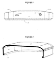
- Figure 1 is a perspective view of a pop and slide container in a closed position comprised of a lid 10 and a base 20 according to an embodiment of the invention.
- the lid 10 and base 20 each comprise a relatively flat surface and side wall 11, 21 that extends the entire perimeter of the surface area giving each component a depth dimension.
- the base 20 further includes a finger indent 22 area at one end that is adapted to receive a user finger during the opening process.
- the lid In its closed position, the lid fits atop the base and is held in place through a mechanical coupling of elements of the lid 10 and base 20. These elements are not visible in this figure but will be described further with reference to later figures.
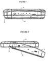
- Figure 2 is a side view of the lid 10 according to an embodiment of the invention.
- the surface area referenced earlier comprises the top of lid 10 whereas the side wall 11 about the perimeter of the surface area comprise what can be considered the side wall(s) of the container.
- Figure 3 is a side view of the base 20 according to an embodiment of the invention.
- the side wall 21 extends upward and away from the base 20 surface area in a substantially perpendicular direction.
- a pair of bumps that protrude outward from the side wall 21.
- the first bump is referred to as a pivot bump 24 and the second bump is referred to as a retention bump 26.
- Identical bumps 24, 26 are also present on the side of the base not seen in this figure.
- the pivot bump 24 and retention bump 26 cooperate with a rolled edge on the side wall 11 of the lid 10 to create a means by which the container can be opened with one hand.
- the tapered sections 28 of the top line of the side wall 21 are functionally important to the opening and closing of the container.
- FIG 4 is a perspective cross-sectional view of the lid 10 according to an embodiment of the invention. This view illustrates how the side wall 11 terminates in a rolled edge 12.
- the rolled edge 12 creates a lip that can be coupled with the pivot bump 24 and the retention bump 26 of base 20. It is to be understood that the lip could be created using an edge other than the rolled edge. Different materials (plastic, paperboard etc%) may be capable of creating this lip using a different edge structure. It is to be understood that manufacturing preferences may adjust the structure depending upon the material used in the lid and or base.
- FIG. 5 is a perspective view of the base 20 according to an embodiment of the invention. All of the elements and features previously described for base 20 are present.
- the side wall 21 circumnavigates the perimeter of the surface area of base 20.
- the tapered sections 28 define high and low points about the side wall 21.
- the pivot bump 24 and retention bump 26 are also visible. This view further shows that the pivot bump 24 protrudes slightly further out from the side wall 21 than the retention bump 26. As will be described in more detail later, this allows the lip formed by the rolled edge 12 of the lid 10 to release from the retention bump 26 but stay in cooperative contact with the pivot bump 24.
- FIG. 6 is a perspective cross-sectional view of the container according to an embodiment of the invention. This illustration shows the container in its closed position.
- the lid 10 fits atop the base 20 such that the lip formed by rolled edge 12 of the lid 10 fits over and is in contact with the pivot bump 24 and retention bump 26 that protrude from side wall 21.
- Figure 7 is a side view of the container in the closed position with hidden lines according to an embodiment of the invention. This figure provides a good illustration of the lip formed by the rolled edge 12 in cooperative contact with the pivot bump 24 and the retention bump 26. This cooperative contact on both sides of the container secure the lid 10 to the base 20.
- Figure 8 is a side view of the container in the initial open position with hidden lines according to an embodiment of the invention. This figure illustrates the position of the container immediately following the "pop" motion that a user applies to open the container.
- the user pinches the end of the container having the finger indent 22.
- the pinching action causes the rolled edge 12 at the far end of the lid to break free of the retention bump 26 while the lip of the rolled edge 12 remains in contact with the pivot bump 24.
- the circular geometry of pivot bump 24 allows the lip of the rolled edge to pivot about pivot bump 24.
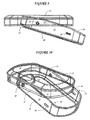
- FIG 9 is a side view of the container in an advanced open position with hidden lines according to an embodiment of the invention.
- the lid 10 has been moved back in a sliding motion to provide more access to the base 20.
- the tapered section 28 provides a degree of clearance for the lid 10 to pivot. The steeper the slope of the tapered section 28, the further the lid 10 can be moved relative to the base 20 to expose more of the open base 20.
- the lip of the rolled edge 12 remains in contact with the pivot bump 24.
- the lid 10 can continue to move away from the base 20 until the lip of the rolled edge 12 encounters too much resistance from the base 20 such that further movement will cause the lid to break free of the pivot bump 24.
- Figure 10 is a perspective view of the container in an advanced open position with hidden lines according to an embodiment of the invention. This figure is essentially a perspective view of Figure 9 and further shows the cooperative relationship between the rolled edge 12 and the pivot bumps 24.
- a user will grasp the container in one hand such that a finger or thumb is positioned within finger indent 22.
- the user presses against the finger indent 22 of base 20 and the top of lid 10. This causes the opposite end of lid 10 to "pop" up after a sufficient force has released the rolled edge 12 from the retention bump 26.
- the user can then pull the lid 10 back in a sliding motion to partially reveal the base 20.
- the lip formed by the rolled edge 12 of lid 10 remains in cooperative contact with pivot bump 24 of base 20.
- the tapered sections 28 of side wall 21 of base 20 allow the lid room to slide and expose a portion of the base 20 such that the user can access the contents of the base 20.
- the user slides the lid 10 back atop base 20 and presses downward sufficiently to cause the rolled edge to snap over and become secured against retention bump 26 of base 20.
- the lip on the top may be a rolled edge, a divot, an undercut, a ledge or any other structure that would provide a means of retainment.
Description
- Disclosed is a container comprising a lid and a base, in accordance with claim 1, and a process for opening it, in accordance with
claim 12. The lid has a top surface and a side wall all about the perimeter of the top surface. The side wall may terminate in a rolled edge. The base has a bottom surface and a side wall all about the perimeter of the bottom surface. The side wall includes a plurality of tapered sections, a plurality of retention bumps that protrude out from the side wall, and a plurality of pivot bumps that protrude out from the side wall. The lid is adapted to fit over the base such that the rolled edge abuts underneath the retention bumps and pivot bumps securing the lid in place when the container is closed. The rolled edge of the lid pivots about and slides along the pivot bumps when the container is in an open position to create an opening for accessing contents of the container. The base can further include a finger indent at one end such that a user can apply pressure simultaneously on the base and the lid at the same end of the container to cause the lid to release from the retention bumps positioned substantially at the other end of the container. The pivot bumps protrude out from the side wall of the base further than the retention bumps so as to let the rolled edge of the lid release from the retention bumps but not the pivot bumps. -
US 2009/236257 A1 discloses a dispenser comprising a base and a cover, the base having a bottom wall, at least two opposing side walls, a front wall and a rear wall, each wall having an upper edge, wherein a portion of the upper edge of each base side wall is angled such that the resulting upper edge of the base rear wall is lower than the upper edge of the base front wall. The base front wall has an aperture. The cover has an upper wall, at least two opposing side walls, a front wall and a rear wall, each wall having a lower edge, wherein a portion of the lower edge of each cover side wall is angled such that the resulting lower edge of the cover rear wall is higher and the lower edge of the cover front wall, and upon assembly of the cover and base, a portion of the base rear wall is exposed, such that placement of downward pressure on a rear area of the cover upper wall elevates the cover front wall, revealing some portion of the aperture in the base front wall, thereby permitting the dispensing of at least some of the contents of the dispenser. Detents on the base engage detents on the cover to assist in maintaining the dispensing device in its closed configuration and also function to assist in maintaining the device in its open configuration after being opened. -
-
Figure 1 is a perspective view of a pop and slide container comprised of a lid and a base according to an embodiment of the invention. -
Figure 2 is a side view of the lid according to an embodiment of the invention. -
Figure 3 is a side view of the base according to an embodiment of the invention. -
Figure 4 is a perspective cross-sectional view of the lid according to an embodiment of the invention. -
Figure 5 is a perspective view of the base according to an embodiment of the invention. -
Figure 6 is a perspective cross-sectional view of the container according to an embodiment of the invention. -
Figure 7 is a side view of the container in the closed position with hidden lines according to an embodiment of the invention. -
Figure 8 is a side view of the container in the initial open position with hidden lines according to an embodiment of the invention. -
Figure 9 is a side view of the container in an advanced open position with hidden lines according to an embodiment of the invention. -
Figure 10 is a perspective view of the container in an advanced open position with hidden lines according to an embodiment of the invention. - Embodiments of the invention describe a container comprised of a base and a lid that is adapted to be held and manipulated by one hand. The container is opened and closed using a pop and slide motion with respect to the lid to expose the contents of the base.
-
Figure 1 is a perspective view of a pop and slide container in a closed position comprised of alid 10 and abase 20 according to an embodiment of the invention. Thelid 10 andbase 20 each comprise a relatively flat surface andside wall base 20 further includes a finger indent 22 area at one end that is adapted to receive a user finger during the opening process. In its closed position, the lid fits atop the base and is held in place through a mechanical coupling of elements of thelid 10 andbase 20. These elements are not visible in this figure but will be described further with reference to later figures. -
Figure 2 is a side view of thelid 10 according to an embodiment of the invention. The surface area referenced earlier comprises the top oflid 10 whereas theside wall 11 about the perimeter of the surface area comprise what can be considered the side wall(s) of the container. -
Figure 3 is a side view of thebase 20 according to an embodiment of the invention. Theside wall 21 extends upward and away from thebase 20 surface area in a substantially perpendicular direction. Also shown are a pair of bumps that protrude outward from theside wall 21. The first bump is referred to as apivot bump 24 and the second bump is referred to as aretention bump 26.Identical bumps pivot bump 24 andretention bump 26 cooperate with a rolled edge on theside wall 11 of thelid 10 to create a means by which the container can be opened with one hand. Also of note are thetapered sections 28 of the top line of theside wall 21. As will be described in more detail later, the taper closest to thepivot bump 24 is functionally important to the opening and closing of the container. -
Figure 4 is a perspective cross-sectional view of thelid 10 according to an embodiment of the invention. This view illustrates how theside wall 11 terminates in a rollededge 12. The rollededge 12 creates a lip that can be coupled with thepivot bump 24 and theretention bump 26 ofbase 20. It is to be understood that the lip could be created using an edge other than the rolled edge. Different materials (plastic, paperboard etc...) may be capable of creating this lip using a different edge structure. It is to be understood that manufacturing preferences may adjust the structure depending upon the material used in the lid and or base. -
Figure 5 is a perspective view of thebase 20 according to an embodiment of the invention. All of the elements and features previously described forbase 20 are present. Theside wall 21 circumnavigates the perimeter of the surface area ofbase 20. Thetapered sections 28 define high and low points about theside wall 21. Thepivot bump 24 andretention bump 26 are also visible. This view further shows that thepivot bump 24 protrudes slightly further out from theside wall 21 than theretention bump 26. As will be described in more detail later, this allows the lip formed by the rollededge 12 of thelid 10 to release from theretention bump 26 but stay in cooperative contact with thepivot bump 24. -
Figure 6 is a perspective cross-sectional view of the container according to an embodiment of the invention. This illustration shows the container in its closed position. Thelid 10 fits atop thebase 20 such that the lip formed by rollededge 12 of thelid 10 fits over and is in contact with thepivot bump 24 andretention bump 26 that protrude fromside wall 21. -
Figure 7 is a side view of the container in the closed position with hidden lines according to an embodiment of the invention. This figure provides a good illustration of the lip formed by the rollededge 12 in cooperative contact with thepivot bump 24 and theretention bump 26. This cooperative contact on both sides of the container secure thelid 10 to thebase 20. -
Figure 8 is a side view of the container in the initial open position with hidden lines according to an embodiment of the invention. This figure illustrates the position of the container immediately following the "pop" motion that a user applies to open the container. The user pinches the end of the container having the finger indent 22. The pinching action causes the rollededge 12 at the far end of the lid to break free of theretention bump 26 while the lip of the rollededge 12 remains in contact with thepivot bump 24. The circular geometry ofpivot bump 24 allows the lip of the rolled edge to pivot aboutpivot bump 24. -
Figure 9 is a side view of the container in an advanced open position with hidden lines according to an embodiment of the invention. In this illustration, thelid 10 has been moved back in a sliding motion to provide more access to thebase 20. The taperedsection 28 provides a degree of clearance for thelid 10 to pivot. The steeper the slope of the taperedsection 28, the further thelid 10 can be moved relative to the base 20 to expose more of theopen base 20. The lip of the rollededge 12 remains in contact with thepivot bump 24. Thelid 10 can continue to move away from the base 20 until the lip of the rollededge 12 encounters too much resistance from the base 20 such that further movement will cause the lid to break free of thepivot bump 24. -
Figure 10 is a perspective view of the container in an advanced open position with hidden lines according to an embodiment of the invention. This figure is essentially a perspective view ofFigure 9 and further shows the cooperative relationship between therolled edge 12 and the pivot bumps 24. - In operation, a user will grasp the container in one hand such that a finger or thumb is positioned within
finger indent 22. Using a pinching motion, the user presses against thefinger indent 22 ofbase 20 and the top oflid 10. This causes the opposite end oflid 10 to "pop" up after a sufficient force has released the rollededge 12 from theretention bump 26. The user can then pull thelid 10 back in a sliding motion to partially reveal thebase 20. The lip formed by the rollededge 12 oflid 10 remains in cooperative contact withpivot bump 24 ofbase 20. Thetapered sections 28 ofside wall 21 ofbase 20 allow the lid room to slide and expose a portion of the base 20 such that the user can access the contents of thebase 20. - To close the container, the user slides the
lid 10 back atopbase 20 and presses downward sufficiently to cause the rolled edge to snap over and become secured againstretention bump 26 ofbase 20. - It is to be understood that a variety of materials may be used to make this package, including but not limited to various types of metal, tin, plastic, and paperboard. The lip on the top may be a rolled edge, a divot, an undercut, a ledge or any other structure that would provide a means of retainment.
- It is believed that the present invention includes many other embodiments that may not be herein described in detail, but would nonetheless be appreciated by those skilled in the art from the disclosures made. Accordingly, this disclosure should not be read as being limited only to the foregoing examples or only to the designated embodiments.
Claims (12)
- A container, comprising:a lid (10) comprising a top surface and a side wall (11); anda base (20) comprising a bottom surface and a side wall (21), wherein the side wall (21) of the base (20) comprises a plurality of tapered sections (28), a plurality of retention bumps (26) that protrude out from the side wall (21), and a plurality of pivot bumps (24) that protrude out from the side wall (21), characterised in that the side wall (11) of the lid (10) has a lip (12) and in
that the lid (10) fits over the base (20) such that the lip (12) of the lid (10) abuts underneath the retention bumps (26) and the pivot bumps (24) to secure the lid (10) to the base (20) when the container is in a closed position, and wherein the lip (12) of the lid (10) pivots about and slides along the pivot bumps (24) to create an opening for accessing contents of the container. - The container of claim 1, wherein the base (20) further comprises a finger indent (22) at one end of the base (20) such that a user can apply pressure simultaneously on the base (20) and the lid (10) at the same end of the container to cause the lid (10) to release from the retention bumps (26) positioned substantially at the other end of the container.
- The container of claim 1, wherein the pivot bumps (24) protrude out from the side wall (21) of the base (20) further than the retention bumps (26).
- The container of claim 1, wherein the tapered sections (28) are positioned at an end of the base (20) closest to the pivot bumps (24).
- The container of claim 1, wherein the lip (12) comprises a structure that provides a means of retainment.
- The container of claim 5, wherein the means of retainment is selected from the group consisting of a rolled edge, a divot, an undercut, and a ledge.
- The container of claim 1, wherein the pivot bumps (24) are circular in shape.
- The container of claim 1, wherein the side wall (11) of the lid (10) and the side wall (21) of the base (20) respectively extend around an entire perimeter of the top surface and the bottom surface.
- The container of claim 1, wherein the side wall (21) of the base (20) extends in a substantially perpendicular direction from the bottom surface.
- The container of claim 1, wherein the tapered sections (28) provide a degree of clearance for the lid (10) to pivot.
- The container of claim 1, wherein the lip (12) remains in contact with the pivot bumps (24).
- A process for opening a container with one hand, comprising:grasping a container of any one of claims 1 to 11 in one hand;applying a pinching motion to one end of the container, which causes the lip (12) of the lid (10) to break free of the retention bumps (26) while the lip (12) remains in contact with the pivot bumps (24) and pivots about the pivot bumps (24); andpulling the lid (10) back in a sliding motion to partially reveal the base (20) while the lip (12) of the lid (10) remains in cooperative contact with the pivot bumps (24).
Applications Claiming Priority (2)
| Application Number | Priority Date | Filing Date | Title |
|---|---|---|---|
| US26749309P | 2009-12-08 | 2009-12-08 | |
| PCT/US2010/059474 WO2011072019A1 (en) | 2009-12-08 | 2010-12-08 | Pop and slide container |
Publications (2)
| Publication Number | Publication Date |
|---|---|
| EP2509885A1 EP2509885A1 (en) | 2012-10-17 |
| EP2509885B1 true EP2509885B1 (en) | 2014-06-18 |
Family
ID=43711073
Family Applications (1)
| Application Number | Title | Priority Date | Filing Date |
|---|---|---|---|
| EP10801735.1A Active EP2509885B1 (en) | 2009-12-08 | 2010-12-08 | Pop and slide container |
Country Status (6)
| Country | Link |
|---|---|
| US (1) | US8540113B2 (en) |
| EP (1) | EP2509885B1 (en) |
| JP (1) | JP5785558B2 (en) |
| CN (1) | CN102858648B (en) |
| ES (1) | ES2475099T3 (en) |
| WO (1) | WO2011072019A1 (en) |
Families Citing this family (24)
| Publication number | Priority date | Publication date | Assignee | Title |
|---|---|---|---|---|
| US8397945B2 (en) | 2010-02-23 | 2013-03-19 | R.J. Reynolds Tobacco Company | Dispensing container |
| US8910781B2 (en) | 2013-01-11 | 2014-12-16 | R.J. Reynolds Tobacco Company | Container for smokeless tobacco products and related packaged product assembly and method |
| US9346594B2 (en) | 2013-03-07 | 2016-05-24 | R. J. Reynolds Tobacco Company | Dispensing container and related method and apparatus |
| US9944439B2 (en) * | 2014-03-06 | 2018-04-17 | Helen Of Troy Limited | Container lid |
| US20160044955A1 (en) | 2014-08-13 | 2016-02-18 | R.J. Reynolds Tobacco Company | Smokeless tobacco products |
| US9445631B1 (en) | 2015-03-20 | 2016-09-20 | R. J. Reynolds Tobacco Company | Container for smokeless tobacco products and related packaged product assembly and method |
| US11147309B2 (en) | 2015-06-10 | 2021-10-19 | R.J. Reynolds Tobacco Company | Container for smokeless tobacco products comprising a pulp material and related packaged product assembly and method |
| USD800060S1 (en) | 2015-07-02 | 2017-10-17 | Kurt Solland | Charging case |
| US10117485B2 (en) | 2015-07-02 | 2018-11-06 | Kurt Solland | Receptacle with pivoting closure |
| US20170158419A1 (en) * | 2015-12-02 | 2017-06-08 | Hubbard Smith | Food Product Package |
| US10532046B2 (en) | 2015-12-03 | 2020-01-14 | Niconovum Usa, Inc. | Multi-phase delivery compositions and products incorporating such compositions |
| US10786002B2 (en) * | 2016-05-18 | 2020-09-29 | Dossie McKinney | Protective cigarette pack case |
| US10773862B2 (en) * | 2016-06-07 | 2020-09-15 | Paq Holdings, Llc | Airtight child resistant case with elongated compartments |
| US20200385183A1 (en) * | 2016-06-07 | 2020-12-10 | Paq Holdings, Llc | Airtight child resistant case with elongated compartments |
| US10414553B2 (en) * | 2016-06-07 | 2019-09-17 | Paq Holdings, Llc | Airtight child resistant case with elongated compartments |
| USD871674S1 (en) * | 2017-01-27 | 2019-12-31 | Glam and Glits Nail Design, Inc. | French dip manicure powder case |
| CN106941041A (en) * | 2017-04-30 | 2017-07-11 | 龚利芬 | A kind of transformer for Switching Power Supply |
| USD846802S1 (en) * | 2017-08-01 | 2019-04-23 | Paris Presents Incorporated | Cleansing palette |
| USD871002S1 (en) | 2017-10-05 | 2019-12-24 | Paris Presents Incorporated | Cleansing palette |
| US10548347B2 (en) | 2018-02-23 | 2020-02-04 | American Snuff Company, Llc | Container for smokeless tobacco products |
| CA3051959A1 (en) * | 2019-06-27 | 2020-12-27 | Dongguan Lk Tin Packaging Co.,Ltd. | Container with security lock |
| CA3080678A1 (en) * | 2019-06-27 | 2020-12-27 | Dongguan Lk Tin Packaging Co.,Ltd. | Container with security lock |
| JP7207209B2 (en) * | 2019-07-11 | 2023-01-18 | 豊田合成株式会社 | Vehicle containment device |
| WO2024074988A1 (en) | 2022-10-04 | 2024-04-11 | R. J. Reynolds Tobacco Company | Stackable arrangement of product containers and related method of stacking |
Family Cites Families (47)
| Publication number | Priority date | Publication date | Assignee | Title |
|---|---|---|---|---|
| US241083A (en) * | 1881-05-03 | Metal box | ||
| US391145A (en) * | 1888-10-16 | haedin | ||
| US1369819A (en) * | 1920-11-12 | 1921-03-01 | George E Krause | Box |
| US1997043A (en) * | 1934-05-23 | 1935-04-09 | Harry Jaffe | Combined cigarette holder and ash tray |
| US2026463A (en) * | 1935-02-11 | 1935-12-31 | Horace H Seay | Container |
| US2093508A (en) * | 1935-05-15 | 1937-09-21 | Liberty Can And Sign Company | Box |
| US2083356A (en) * | 1935-09-13 | 1937-06-08 | Liberty Can And Sign Company | Box |
| US2219486A (en) * | 1938-10-27 | 1940-10-29 | Nyden Robert | Container |
| US2219487A (en) * | 1938-10-27 | 1940-10-29 | Nyden Robert | Sheet metal container |
| US2295747A (en) * | 1940-02-15 | 1942-09-15 | Clark Mfg Co J L | Slide cover box |
| US2304898A (en) * | 1940-07-31 | 1942-12-15 | Continental Can Co | Dispensing container |
| US2399470A (en) * | 1944-05-24 | 1946-04-30 | Allied Plastics Co | Cigarette case |
| US2415357A (en) * | 1944-09-04 | 1947-02-04 | Harry Morris Associates | Integral latch for sliding pivoted closures |
| US2492864A (en) * | 1945-02-21 | 1949-12-27 | Continental Can Co | Tablet box |
| US2661119A (en) * | 1952-09-24 | 1953-12-01 | Nat Dairy Res Lab Inc | Container and closure therefor |
| US2867348A (en) * | 1955-03-24 | 1959-01-06 | F N Burt Company Inc | Container |
| US2806626A (en) * | 1955-04-15 | 1957-09-17 | Nyden Robert | Tablet boxes |
| US2813653A (en) * | 1955-04-28 | 1957-11-19 | Arnold R Grossman | Display receptacle |
| US2906428A (en) * | 1957-10-28 | 1959-09-29 | Continental Can Co | Tablet box |
| US3782584A (en) * | 1972-06-09 | 1974-01-01 | Rich P | Pill box having safety sliding closure |
| JPH059849Y2 (en) * | 1985-04-16 | 1993-03-11 | ||
| US4946057A (en) * | 1989-02-13 | 1990-08-07 | Connolly Brian D | Storage box with locking lid and wall mounting apparatus |
| JPH0542190U (en) * | 1991-10-30 | 1993-06-08 | 日立マクセル株式会社 | Disk card storage case |
| JP3039515U (en) * | 1996-10-15 | 1997-07-22 | 鴻杰 蔡 | Standing and expandable packaging case for sticks |
| JP3047078U (en) * | 1997-05-30 | 1998-03-31 | 株式会社ワット | Portable accessory container or accessory with cap |
| JP3293063B2 (en) * | 1997-12-08 | 2002-06-17 | カシオ計算機株式会社 | Lid opening and closing structure |
| CN2450125Y (en) * | 2000-08-23 | 2001-09-26 | 东莞艺爵包装盒有限公司 | Improved packing show device |
| JP2002068353A (en) * | 2000-08-29 | 2002-03-08 | Sony Corp | Housing case |
| US6736261B1 (en) | 2001-09-19 | 2004-05-18 | Timothy Frederick Thomas | Sliding shell package for smoking articles and method |
| US20040056035A1 (en) * | 2002-09-25 | 2004-03-25 | Mars, Incorporated | Dispenser with stowable cover |
| US7014039B2 (en) * | 2003-06-19 | 2006-03-21 | R.J. Reynolds Tobacco Company | Sliding shell package for smoking articles |
| USD510859S1 (en) * | 2004-03-15 | 2005-10-25 | Kraft Foods Holdings, Inc. | Container assembly for food items |
| USD534068S1 (en) * | 2005-09-14 | 2006-12-26 | Crown Packaging Technology, Inc. | Container |
| US7721908B2 (en) * | 2006-01-03 | 2010-05-25 | J.L. Clark, Inc. | Container having a slideable cover |
| WO2008073360A2 (en) * | 2006-12-12 | 2008-06-19 | Meadwestvaco Corporation | Package with pivoting cover |
| CN201056353Y (en) * | 2007-05-13 | 2008-05-07 | 张利 | Packing box |
| US7878324B2 (en) | 2007-11-30 | 2011-02-01 | Philip Morris Usa Inc. | Pocket-size container for consumer items |
| US8033425B2 (en) * | 2008-03-04 | 2011-10-11 | R.J. Reynolds Tobacco Company | Dispensing container |
| US20090223841A1 (en) * | 2008-03-07 | 2009-09-10 | R.J. Reynolds Tobacco Company | Cigarette tin with internal ramp |
| US7798319B1 (en) | 2008-03-11 | 2010-09-21 | U.S. Smokeless Tobacco Company | Container device for tobacco articles |
| US7757858B2 (en) * | 2008-03-20 | 2010-07-20 | Harley Cross | Dispensing container device |
| US7946450B2 (en) | 2008-04-25 | 2011-05-24 | R.J. Reynolds Tobacco Company | Dispensing container |
| JP3143142U (en) * | 2008-04-28 | 2008-07-10 | デリカフローラ株式会社 | Portable container. |
| US20100072206A1 (en) * | 2008-09-25 | 2010-03-25 | Tinscape Llc | Container with window |
| US9248935B2 (en) * | 2008-12-01 | 2016-02-02 | R.J. Reynolds Tobacco Company | Dual cavity sliding dispenser |
| US8096411B2 (en) | 2010-01-12 | 2012-01-17 | R. J. Reynolds Tabacco Company | Dispensing container |
| US9981783B2 (en) * | 2011-08-12 | 2018-05-29 | J.L. Clark, Inc. | Metal container with slideable top |
-
2010
- 2010-12-08 CN CN201080062818.6A patent/CN102858648B/en active Active
- 2010-12-08 ES ES10801735.1T patent/ES2475099T3/en active Active
- 2010-12-08 JP JP2012543247A patent/JP5785558B2/en active Active
- 2010-12-08 WO PCT/US2010/059474 patent/WO2011072019A1/en active Application Filing
- 2010-12-08 EP EP10801735.1A patent/EP2509885B1/en active Active
-
2012
- 2012-06-05 US US13/488,627 patent/US8540113B2/en active Active
Also Published As
| Publication number | Publication date |
|---|---|
| US20120285125A1 (en) | 2012-11-15 |
| EP2509885A1 (en) | 2012-10-17 |
| CN102858648B (en) | 2015-04-08 |
| WO2011072019A1 (en) | 2011-06-16 |
| JP2013512831A (en) | 2013-04-18 |
| CN102858648A (en) | 2013-01-02 |
| US8540113B2 (en) | 2013-09-24 |
| ES2475099T3 (en) | 2014-07-10 |
| JP5785558B2 (en) | 2015-09-30 |
Similar Documents
| Publication | Publication Date | Title |
|---|---|---|
| EP2509885B1 (en) | Pop and slide container | |
| US7938266B2 (en) | Dispensing container device | |
| US10065771B2 (en) | Container lid having selectively coverable access opening | |
| US5806757A (en) | Device for unsealing pour opening of liquid container | |
| JP5579171B2 (en) | Beverage can lid seal | |
| WO2015088744A1 (en) | Container for a cylindrical object | |
| GB2337041A (en) | A container | |
| US20030159965A1 (en) | Dispenser having one touch flip top opening | |
| US7124909B1 (en) | Hinged lid container | |
| US7661555B1 (en) | Single dispensing film strip container | |
| JP3303062B2 (en) | cap | |
| JP2583054Y2 (en) | Spout with lid | |
| JPS6335686Y2 (en) | ||
| KR102649159B1 (en) | A Container Opening Device, a Closure Arrangement for a Container, and a Container | |
| KR200456405Y1 (en) | opener for receptacle | |
| JPH1086981A (en) | Tissue box preventing tissue from dropping | |
| JP4263379B2 (en) | Spring hinge cap | |
| JP6501697B2 (en) | Cup container with lid | |
| JP4629468B2 (en) | Packaging container | |
| WO1996007341A1 (en) | An easy to use one handed self-opening hinged package | |
| JPH0515843Y2 (en) | ||
| KR200398961Y1 (en) | Drag and press type opener on end for can | |
| KR20130009358A (en) | Easily openable cover structure of can | |
| JP2001151233A (en) | Pull-top can with lid | |
| JPH0369494A (en) | Powder and particle material takeout |
Legal Events
| Date | Code | Title | Description |
|---|---|---|---|
| PUAI | Public reference made under article 153(3) epc to a published international application that has entered the european phase |
Free format text: ORIGINAL CODE: 0009012 |
|
| 17P | Request for examination filed |
Effective date: 20120619 |
|
| AK | Designated contracting states |
Kind code of ref document: A1 Designated state(s): AL AT BE BG CH CY CZ DE DK EE ES FI FR GB GR HR HU IE IS IT LI LT LU LV MC MK MT NL NO PL PT RO RS SE SI SK SM TR |
|
| DAX | Request for extension of the european patent (deleted) | ||
| 17Q | First examination report despatched |
Effective date: 20130408 |
|
| GRAP | Despatch of communication of intention to grant a patent |
Free format text: ORIGINAL CODE: EPIDOSNIGR1 |
|
| INTG | Intention to grant announced |
Effective date: 20140113 |
|
| GRAS | Grant fee paid |
Free format text: ORIGINAL CODE: EPIDOSNIGR3 |
|
| GRAA | (expected) grant |
Free format text: ORIGINAL CODE: 0009210 |
|
| AK | Designated contracting states |
Kind code of ref document: B1 Designated state(s): AL AT BE BG CH CY CZ DE DK EE ES FI FR GB GR HR HU IE IS IT LI LT LU LV MC MK MT NL NO PL PT RO RS SE SI SK SM TR |
|
| REG | Reference to a national code |
Ref country code: GB Ref legal event code: FG4D |
|
| REG | Reference to a national code |
Ref country code: CH Ref legal event code: NV Representative=s name: ISLER AND PEDRAZZINI AG, CH Ref country code: CH Ref legal event code: EP |
|
| REG | Reference to a national code |
Ref country code: ES Ref legal event code: FG2A Ref document number: 2475099 Country of ref document: ES Kind code of ref document: T3 Effective date: 20140710 |
|
| REG | Reference to a national code |
Ref country code: AT Ref legal event code: REF Ref document number: 673194 Country of ref document: AT Kind code of ref document: T Effective date: 20140715 |
|
| REG | Reference to a national code |
Ref country code: IE Ref legal event code: FG4D |
|
| REG | Reference to a national code |
Ref country code: DE Ref legal event code: R096 Ref document number: 602010016879 Country of ref document: DE Effective date: 20140731 |
|
| REG | Reference to a national code |
Ref country code: SE Ref legal event code: TRGR |
|
| PG25 | Lapsed in a contracting state [announced via postgrant information from national office to epo] |
Ref country code: GR Free format text: LAPSE BECAUSE OF FAILURE TO SUBMIT A TRANSLATION OF THE DESCRIPTION OR TO PAY THE FEE WITHIN THE PRESCRIBED TIME-LIMIT Effective date: 20140919 Ref country code: CY Free format text: LAPSE BECAUSE OF FAILURE TO SUBMIT A TRANSLATION OF THE DESCRIPTION OR TO PAY THE FEE WITHIN THE PRESCRIBED TIME-LIMIT Effective date: 20140618 Ref country code: LT Free format text: LAPSE BECAUSE OF FAILURE TO SUBMIT A TRANSLATION OF THE DESCRIPTION OR TO PAY THE FEE WITHIN THE PRESCRIBED TIME-LIMIT Effective date: 20140618 Ref country code: NO Free format text: LAPSE BECAUSE OF FAILURE TO SUBMIT A TRANSLATION OF THE DESCRIPTION OR TO PAY THE FEE WITHIN THE PRESCRIBED TIME-LIMIT Effective date: 20140918 Ref country code: FI Free format text: LAPSE BECAUSE OF FAILURE TO SUBMIT A TRANSLATION OF THE DESCRIPTION OR TO PAY THE FEE WITHIN THE PRESCRIBED TIME-LIMIT Effective date: 20140618 |
|
| REG | Reference to a national code |
Ref country code: NL Ref legal event code: VDEP Effective date: 20140618 |
|
| REG | Reference to a national code |
Ref country code: AT Ref legal event code: MK05 Ref document number: 673194 Country of ref document: AT Kind code of ref document: T Effective date: 20140618 |
|
| REG | Reference to a national code |
Ref country code: LT Ref legal event code: MG4D |
|
| PG25 | Lapsed in a contracting state [announced via postgrant information from national office to epo] |
Ref country code: LV Free format text: LAPSE BECAUSE OF FAILURE TO SUBMIT A TRANSLATION OF THE DESCRIPTION OR TO PAY THE FEE WITHIN THE PRESCRIBED TIME-LIMIT Effective date: 20140618 Ref country code: RS Free format text: LAPSE BECAUSE OF FAILURE TO SUBMIT A TRANSLATION OF THE DESCRIPTION OR TO PAY THE FEE WITHIN THE PRESCRIBED TIME-LIMIT Effective date: 20140618 Ref country code: HR Free format text: LAPSE BECAUSE OF FAILURE TO SUBMIT A TRANSLATION OF THE DESCRIPTION OR TO PAY THE FEE WITHIN THE PRESCRIBED TIME-LIMIT Effective date: 20140618 |
|
| PG25 | Lapsed in a contracting state [announced via postgrant information from national office to epo] |
Ref country code: EE Free format text: LAPSE BECAUSE OF FAILURE TO SUBMIT A TRANSLATION OF THE DESCRIPTION OR TO PAY THE FEE WITHIN THE PRESCRIBED TIME-LIMIT Effective date: 20140618 Ref country code: SK Free format text: LAPSE BECAUSE OF FAILURE TO SUBMIT A TRANSLATION OF THE DESCRIPTION OR TO PAY THE FEE WITHIN THE PRESCRIBED TIME-LIMIT Effective date: 20140618 Ref country code: CZ Free format text: LAPSE BECAUSE OF FAILURE TO SUBMIT A TRANSLATION OF THE DESCRIPTION OR TO PAY THE FEE WITHIN THE PRESCRIBED TIME-LIMIT Effective date: 20140618 Ref country code: PT Free format text: LAPSE BECAUSE OF FAILURE TO SUBMIT A TRANSLATION OF THE DESCRIPTION OR TO PAY THE FEE WITHIN THE PRESCRIBED TIME-LIMIT Effective date: 20141020 Ref country code: RO Free format text: LAPSE BECAUSE OF FAILURE TO SUBMIT A TRANSLATION OF THE DESCRIPTION OR TO PAY THE FEE WITHIN THE PRESCRIBED TIME-LIMIT Effective date: 20140618 |
|
| PG25 | Lapsed in a contracting state [announced via postgrant information from national office to epo] |
Ref country code: AT Free format text: LAPSE BECAUSE OF FAILURE TO SUBMIT A TRANSLATION OF THE DESCRIPTION OR TO PAY THE FEE WITHIN THE PRESCRIBED TIME-LIMIT Effective date: 20140618 Ref country code: IS Free format text: LAPSE BECAUSE OF FAILURE TO SUBMIT A TRANSLATION OF THE DESCRIPTION OR TO PAY THE FEE WITHIN THE PRESCRIBED TIME-LIMIT Effective date: 20141018 Ref country code: PL Free format text: LAPSE BECAUSE OF FAILURE TO SUBMIT A TRANSLATION OF THE DESCRIPTION OR TO PAY THE FEE WITHIN THE PRESCRIBED TIME-LIMIT Effective date: 20140618 Ref country code: NL Free format text: LAPSE BECAUSE OF FAILURE TO SUBMIT A TRANSLATION OF THE DESCRIPTION OR TO PAY THE FEE WITHIN THE PRESCRIBED TIME-LIMIT Effective date: 20140618 |
|
| REG | Reference to a national code |
Ref country code: DE Ref legal event code: R097 Ref document number: 602010016879 Country of ref document: DE |
|
| PLBE | No opposition filed within time limit |
Free format text: ORIGINAL CODE: 0009261 |
|
| STAA | Information on the status of an ep patent application or granted ep patent |
Free format text: STATUS: NO OPPOSITION FILED WITHIN TIME LIMIT |
|
| PG25 | Lapsed in a contracting state [announced via postgrant information from national office to epo] |
Ref country code: DK Free format text: LAPSE BECAUSE OF FAILURE TO SUBMIT A TRANSLATION OF THE DESCRIPTION OR TO PAY THE FEE WITHIN THE PRESCRIBED TIME-LIMIT Effective date: 20140618 |
|
| 26N | No opposition filed |
Effective date: 20150319 |
|
| PG25 | Lapsed in a contracting state [announced via postgrant information from national office to epo] |
Ref country code: BE Free format text: LAPSE BECAUSE OF FAILURE TO SUBMIT A TRANSLATION OF THE DESCRIPTION OR TO PAY THE FEE WITHIN THE PRESCRIBED TIME-LIMIT Effective date: 20140618 |
|
| REG | Reference to a national code |
Ref country code: DE Ref legal event code: R082 Ref document number: 602010016879 Country of ref document: DE Representative=s name: HOEGER, STELLRECHT & PARTNER PATENTANWAELTE MB, DE |
|
| PG25 | Lapsed in a contracting state [announced via postgrant information from national office to epo] |
Ref country code: SI Free format text: LAPSE BECAUSE OF FAILURE TO SUBMIT A TRANSLATION OF THE DESCRIPTION OR TO PAY THE FEE WITHIN THE PRESCRIBED TIME-LIMIT Effective date: 20140618 Ref country code: LU Free format text: LAPSE BECAUSE OF FAILURE TO SUBMIT A TRANSLATION OF THE DESCRIPTION OR TO PAY THE FEE WITHIN THE PRESCRIBED TIME-LIMIT Effective date: 20141208 |
|
| REG | Reference to a national code |
Ref country code: IE Ref legal event code: MM4A |
|
| PG25 | Lapsed in a contracting state [announced via postgrant information from national office to epo] |
Ref country code: IE Free format text: LAPSE BECAUSE OF NON-PAYMENT OF DUE FEES Effective date: 20141208 |
|
| REG | Reference to a national code |
Ref country code: FR Ref legal event code: PLFP Year of fee payment: 6 |
|
| PG25 | Lapsed in a contracting state [announced via postgrant information from national office to epo] |
Ref country code: SM Free format text: LAPSE BECAUSE OF FAILURE TO SUBMIT A TRANSLATION OF THE DESCRIPTION OR TO PAY THE FEE WITHIN THE PRESCRIBED TIME-LIMIT Effective date: 20140618 |
|
| PG25 | Lapsed in a contracting state [announced via postgrant information from national office to epo] |
Ref country code: MC Free format text: LAPSE BECAUSE OF FAILURE TO SUBMIT A TRANSLATION OF THE DESCRIPTION OR TO PAY THE FEE WITHIN THE PRESCRIBED TIME-LIMIT Effective date: 20140618 |
|
| PG25 | Lapsed in a contracting state [announced via postgrant information from national office to epo] |
Ref country code: BG Free format text: LAPSE BECAUSE OF FAILURE TO SUBMIT A TRANSLATION OF THE DESCRIPTION OR TO PAY THE FEE WITHIN THE PRESCRIBED TIME-LIMIT Effective date: 20140618 |
|
| PG25 | Lapsed in a contracting state [announced via postgrant information from national office to epo] |
Ref country code: HU Free format text: LAPSE BECAUSE OF FAILURE TO SUBMIT A TRANSLATION OF THE DESCRIPTION OR TO PAY THE FEE WITHIN THE PRESCRIBED TIME-LIMIT; INVALID AB INITIO Effective date: 20101208 Ref country code: MT Free format text: LAPSE BECAUSE OF FAILURE TO SUBMIT A TRANSLATION OF THE DESCRIPTION OR TO PAY THE FEE WITHIN THE PRESCRIBED TIME-LIMIT Effective date: 20140618 Ref country code: TR Free format text: LAPSE BECAUSE OF FAILURE TO SUBMIT A TRANSLATION OF THE DESCRIPTION OR TO PAY THE FEE WITHIN THE PRESCRIBED TIME-LIMIT Effective date: 20140618 |
|
| REG | Reference to a national code |
Ref country code: FR Ref legal event code: PLFP Year of fee payment: 7 |
|
| REG | Reference to a national code |
Ref country code: FR Ref legal event code: PLFP Year of fee payment: 8 |
|
| PG25 | Lapsed in a contracting state [announced via postgrant information from national office to epo] |
Ref country code: MK Free format text: LAPSE BECAUSE OF FAILURE TO SUBMIT A TRANSLATION OF THE DESCRIPTION OR TO PAY THE FEE WITHIN THE PRESCRIBED TIME-LIMIT Effective date: 20140618 |
|
| PG25 | Lapsed in a contracting state [announced via postgrant information from national office to epo] |
Ref country code: AL Free format text: LAPSE BECAUSE OF FAILURE TO SUBMIT A TRANSLATION OF THE DESCRIPTION OR TO PAY THE FEE WITHIN THE PRESCRIBED TIME-LIMIT Effective date: 20140618 |
|
| REG | Reference to a national code |
Ref country code: DE Ref legal event code: R082 Ref document number: 602010016879 Country of ref document: DE Representative=s name: HOEGER, STELLRECHT & PARTNER PATENTANWAELTE MB, DE |
|
| PGFP | Annual fee paid to national office [announced via postgrant information from national office to epo] |
Ref country code: ES Payment date: 20230112 Year of fee payment: 13 Ref country code: CH Payment date: 20230101 Year of fee payment: 13 |
|
| P01 | Opt-out of the competence of the unified patent court (upc) registered |
Effective date: 20230504 |
|
| PGFP | Annual fee paid to national office [announced via postgrant information from national office to epo] |
Ref country code: FR Payment date: 20230929 Year of fee payment: 14 |
|
| PGFP | Annual fee paid to national office [announced via postgrant information from national office to epo] |
Ref country code: GB Payment date: 20231019 Year of fee payment: 14 |
|
| PGFP | Annual fee paid to national office [announced via postgrant information from national office to epo] |
Ref country code: SE Payment date: 20231002 Year of fee payment: 14 Ref country code: IT Payment date: 20231110 Year of fee payment: 14 Ref country code: DE Payment date: 20231010 Year of fee payment: 14 |
|
| PGFP | Annual fee paid to national office [announced via postgrant information from national office to epo] |
Ref country code: ES Payment date: 20240111 Year of fee payment: 14 |