EP2509666B1 - Dosisindikator - Google Patents
Dosisindikator Download PDFInfo
- Publication number
- EP2509666B1 EP2509666B1 EP10790498.9A EP10790498A EP2509666B1 EP 2509666 B1 EP2509666 B1 EP 2509666B1 EP 10790498 A EP10790498 A EP 10790498A EP 2509666 B1 EP2509666 B1 EP 2509666B1
- Authority
- EP
- European Patent Office
- Prior art keywords
- worm
- axis
- dose counter
- actuator
- dose
- Prior art date
- Legal status (The legal status is an assumption and is not a legal conclusion. Google has not performed a legal analysis and makes no representation as to the accuracy of the status listed.)
- Active
Links
- 230000033001 locomotion Effects 0.000 claims description 43
- 239000000443 aerosol Substances 0.000 claims description 27
- 239000003814 drug Substances 0.000 claims description 27
- 230000003993 interaction Effects 0.000 claims description 23
- 229940071648 metered dose inhaler Drugs 0.000 claims description 13
- 238000009472 formulation Methods 0.000 description 7
- 239000000203 mixture Substances 0.000 description 7
- 230000002349 favourable effect Effects 0.000 description 5
- 230000000717 retained effect Effects 0.000 description 5
- 229940079593 drug Drugs 0.000 description 4
- 238000004519 manufacturing process Methods 0.000 description 4
- 230000036961 partial effect Effects 0.000 description 4
- 230000000670 limiting effect Effects 0.000 description 3
- 230000002093 peripheral effect Effects 0.000 description 3
- 230000000630 rising effect Effects 0.000 description 3
- 239000012780 transparent material Substances 0.000 description 3
- 239000002184 metal Substances 0.000 description 2
- 239000000546 pharmaceutical excipient Substances 0.000 description 2
- 239000004033 plastic Substances 0.000 description 2
- 239000003380 propellant Substances 0.000 description 2
- 230000000284 resting effect Effects 0.000 description 2
- YFMFNYKEUDLDTL-UHFFFAOYSA-N 1,1,1,2,3,3,3-heptafluoropropane Chemical compound FC(F)(F)C(F)C(F)(F)F YFMFNYKEUDLDTL-UHFFFAOYSA-N 0.000 description 1
- LVGUZGTVOIAKKC-UHFFFAOYSA-N 1,1,1,2-tetrafluoroethane Chemical compound FCC(F)(F)F LVGUZGTVOIAKKC-UHFFFAOYSA-N 0.000 description 1
- 229910000639 Spring steel Inorganic materials 0.000 description 1
- 229910000831 Steel Inorganic materials 0.000 description 1
- 239000013543 active substance Substances 0.000 description 1
- 208000006673 asthma Diseases 0.000 description 1
- 230000009286 beneficial effect Effects 0.000 description 1
- 229940124630 bronchodilator Drugs 0.000 description 1
- 239000003086 colorant Substances 0.000 description 1
- 230000007797 corrosion Effects 0.000 description 1
- 238000005260 corrosion Methods 0.000 description 1
- 230000003247 decreasing effect Effects 0.000 description 1
- 230000001419 dependent effect Effects 0.000 description 1
- 239000006185 dispersion Substances 0.000 description 1
- 230000002708 enhancing effect Effects 0.000 description 1
- 238000010348 incorporation Methods 0.000 description 1
- 230000001939 inductive effect Effects 0.000 description 1
- 230000000977 initiatory effect Effects 0.000 description 1
- 239000007769 metal material Substances 0.000 description 1
- 238000000465 moulding Methods 0.000 description 1
- 230000003647 oxidation Effects 0.000 description 1
- 238000007254 oxidation reaction Methods 0.000 description 1
- 239000000843 powder Substances 0.000 description 1
- 230000002441 reversible effect Effects 0.000 description 1
- 239000002904 solvent Substances 0.000 description 1
- 239000007921 spray Substances 0.000 description 1
- 239000010959 steel Substances 0.000 description 1
- 150000003431 steroids Chemical class 0.000 description 1
- 239000004094 surface-active agent Substances 0.000 description 1
- 230000001360 synchronised effect Effects 0.000 description 1
- 230000000007 visual effect Effects 0.000 description 1
Images


Classifications
-
- A—HUMAN NECESSITIES
- A61—MEDICAL OR VETERINARY SCIENCE; HYGIENE
- A61M—DEVICES FOR INTRODUCING MEDIA INTO, OR ONTO, THE BODY; DEVICES FOR TRANSDUCING BODY MEDIA OR FOR TAKING MEDIA FROM THE BODY; DEVICES FOR PRODUCING OR ENDING SLEEP OR STUPOR
- A61M15/00—Inhalators
- A61M15/009—Inhalators using medicine packages with incorporated spraying means, e.g. aerosol cans
-
- A—HUMAN NECESSITIES
- A61—MEDICAL OR VETERINARY SCIENCE; HYGIENE
- A61M—DEVICES FOR INTRODUCING MEDIA INTO, OR ONTO, THE BODY; DEVICES FOR TRANSDUCING BODY MEDIA OR FOR TAKING MEDIA FROM THE BODY; DEVICES FOR PRODUCING OR ENDING SLEEP OR STUPOR
- A61M15/00—Inhalators
- A61M15/0065—Inhalators with dosage or measuring devices
- A61M15/0068—Indicating or counting the number of dispensed doses or of remaining doses
- A61M15/007—Mechanical counters
- A61M15/0071—Mechanical counters having a display or indicator
- A61M15/0073—Mechanical counters having a display or indicator on a ring
-
- A—HUMAN NECESSITIES
- A61—MEDICAL OR VETERINARY SCIENCE; HYGIENE
- A61M—DEVICES FOR INTRODUCING MEDIA INTO, OR ONTO, THE BODY; DEVICES FOR TRANSDUCING BODY MEDIA OR FOR TAKING MEDIA FROM THE BODY; DEVICES FOR PRODUCING OR ENDING SLEEP OR STUPOR
- A61M15/00—Inhalators
- A61M15/0065—Inhalators with dosage or measuring devices
- A61M15/0068—Indicating or counting the number of dispensed doses or of remaining doses
- A61M15/007—Mechanical counters
- A61M15/0071—Mechanical counters having a display or indicator
- A61M15/0075—Mechanical counters having a display or indicator on a disc
-
- G—PHYSICS
- G06—COMPUTING; CALCULATING OR COUNTING
- G06M—COUNTING MECHANISMS; COUNTING OF OBJECTS NOT OTHERWISE PROVIDED FOR
- G06M1/00—Design features of general application
- G06M1/14—Design features of general application for transferring a condition from one stage to a higher stage
- G06M1/16—Design features of general application for transferring a condition from one stage to a higher stage self-operating, e.g. by Geneva mechanism
- G06M1/163—Design features of general application for transferring a condition from one stage to a higher stage self-operating, e.g. by Geneva mechanism with drums
-
- G—PHYSICS
- G06—COMPUTING; CALCULATING OR COUNTING
- G06M—COUNTING MECHANISMS; COUNTING OF OBJECTS NOT OTHERWISE PROVIDED FOR
- G06M1/00—Design features of general application
- G06M1/22—Design features of general application for visual indication of the result of count on counting mechanisms, e.g. by window with magnifying lens
- G06M1/24—Drums; Dials; Pointers
- G06M1/248—Discs
Definitions
- This invention relates to dose counters for dispensers and in particular to dose counters for use with metered dose inhalers comprising a container for medicament equipped with a reciprocal actuation means, such as a valve, to dispense a dose of medicament from the container.
- a reciprocal actuation means such as a valve
- inhalation has become a widely used route for delivering bronchodilator drugs and steroids to the airways of asthmatic patients. More recently, inhalation from a pressurised inhaler has been a route selected for administration of other drugs that are not primarily concerned with treatment of a bronchial malady.
- a pressurised metered dose inhaler generally comprises an aerosol container equipped with a metered dose dispensing valve (which is generally herein referred to as a canister) and an actuator.
- the actuator generally comprises a nozzle block to retain the canister (typically the valve stem of the metering valve) and a user-port such as a mouthpiece, as well as an optional, but typically used, cylindrical housing for housing the aerosol container.
- the aerosol container contains a pressurised aerosol formulation that generally comprises a liquefied propellant and a medicament and, if desired and/or needed, one or more excipients such as a surfactant or a solvent.
- the medicament may be in the form of a dispersion or in solution in the aerosol formulation.
- Metered dose dispensing valves generally comprise a valve stem that is moved inwardly with respect to the container to dispense a metered dose of aerosol formulation.
- the canister is inserted into the actuator with the valve stem engaging the nozzle block of the actuator.
- a patient places their lips round the mouthpiece and presses the base of the aerosol container causing the container to move relative to the valve stem to fire a dose of medicament through the mouthpiece.
- WO 2007/124406 (Stuart et al. ), WO 06/062450 (Hörlines ) and WO 1993/024167 (Holroyd ).
- Some are mounted onto the base of the aerosol container e.g. WO 1999/57019
- some are mounted onto the ferrule of the aerosol container e.g. WO 1998/56444
- others are retained within the interior of the actuator beneath the aerosol container in the space near and or around the nozzle block e.g. WO 2007/124406 and WO 2005/060535 ).
- Incorporation of the type of dose counters retained within the interior of the actuator beneath the aerosol container in the space near and/or around the nozzle block is generally advantageous in that the use of such dose counters can allow for the provision of an inhaler without any change - other than the provision of a dose-indication - from the perspective of the users, said users often being quite conservative and anxious about any change.
- a dose counter retained within the interior of the actuator can allow for the provision of an inhaler without any change in form or size, if the size of the dose counter is small enough to be located entirely in the space beneath the aerosol container near and/or around the nozzle block.
- one aspect of the present invention provides a dose counter for use with an inhaler comprising a container for medicament equipped with a reciprocal actuation means to dispense a dose of medicament therefrom, said reciprocal actuation means operating along a first axis, the dose counter comprising an indicator member rotatable about a second axis, wherein the indicator member is constructed and arranged to undergo predetermined count-indicating motion when one or more doses are dispensed,characterized in that the second axis is disposed at an obtuse angle with respect to the first axis, and the dose counter further comprises a worm rotatable about a worm axis, wherein said worm comprises a worm shaft and a worm thread and is arranged to drive said indicator member, and wherein the worm axis and the second axis do not intersect and are disposed at an obtuse angle of 95 degrees or greater relative to each other.
- an indicator member By configuring and arranging an indicator member at an obtuse angle relative to the first axis (the axis of the actuation) where the indicator member is driven by a worm, whose axis is not perpendicular to the axis of rotation of the indicator member, it has been found that one may provide desirably small dose counters that can count and indicate usage of 200-plus doses and at the same time which may be desirably robust e.g. in manufacture and/or in effective usage.
- the worm axis and first axis are not coaxial.
- the counter it is favourable to arrange the counter such that the worm axis is disposed from an angle of 180 degrees ("exact parallel alignment") to an angle of 160 degrees with respect to the first axis, more favourably the worm axis is in parallel alignment to the first axis.
- the second axis is also disposed at an obtuse angle with respect to the worm axis.
- first and second axes intersect. Desirably the first and worm axes do not intersect.
- the first and second axes are favourably disposed at an obtuse angle of 145 degrees or less relative to each other, more favourably 135 degrees or less relative to each other, even more favourably 125 degrees or less relative to each other, most favourably 120 degrees or less relative to each other.
- the first and second axes are favourably disposed at an obtuse angle of 95 degrees or greater relative to each other, more favourably 100 degrees or greater relative to each other, even more favourably 105 degrees or greater relative to each other, most favourably 110 degrees or greater relative to each other.
- the indicator member comprises a region for interaction with the worm, wherein this region of the indicator member and the worm are desirably configured and arranged such that at least one portion of the region of the indicator member meshes with at least one portion of the thread of the worm. It has been found advantageous to configure and arrange this region of the indicator member like a worm wheel.
- a worm wheel may be a separate component affixed to the indicator member or indirectly coupled to the indicator member or such a worm wheel may be integral to the indicator member.
- the cross-sectional radius of the worm from the worm axis to the outer edge of the worm flight (thread) favourably generally increases along the worm axis,.
- the cross-sectional diameter of the worm shaft may favourably generally increase along the worm axis and/or the cross-sectional width of the worm thread perpendicular to the worm axis may favourably generally increase along the worm axis.
- a further aspect of the present invention includes an actuator for use with or as part of a dispenser, said actuator comprising a dose counter as described herein.
- the dose counter is mounted within the interior of the actuator.
- a dispenser comprising a dose counter as described herein and a dispenser comprising an actuator as described herein.
- a dispenser comprising a dose counter as described herein and a dispenser comprising an actuator as described herein.
- a dispenser may be a metered dose dispenser, more favourably a metered dose inhaler, and most favourably a pressurised metered dose inhaler.
- the dose counter is mounted within the interior of the actuator such that in use, the dose counter is generally positioned beneath the aerosol container (or the canister including said container and metering valve) and/or around a nozzle block of the actuator.
- FIG 1 provides a schematic illustration of a vertical cross-section through an exemplary pressurized metered dose inhaler (5).
- the illustrated pressurised metered dose inhaler (5) comprises the following components: a canister (15), an actuator (20) and a dose counter (200).
- the dose counter is only shown diagrammatically with its outer profile in an outline form, and advantageously it is a dose counter in accordance with the present invention, in particular the exemplary dose counter illustrated in Figure 2 or alternatively the dose counter illustrated in Figure 3 (both discussed in detail infra )).
- the canister (15) includes an aerosol container (16) equipped with a metering valve (17) secured via a ferrule (18).
- the metering valve (17) includes inter alia a valve stem (19), generally a valve body (23) defining a metering chamber, and a spring (24).
- the metering valve (17) may also include an outer valve body (25) serving as a bottle emptier and/or defining a pre-metering chamber.
- the container (16) typically contains an aerosol formulation that generally comprises at least one active agent (such as at least one medicament) and liquefied propellant (e.g. HFA 134a and/or HFA 227), and optionally one or more excipients.
- the actuator (20) and canister (15) are arranged so that the valve stem (19) engages with a nozzle block (21) provided within the actuator so that the canister is thus retained in the actuator.
- the user actuates the pressurized metered dose inhaler (5) to dispense a single dose of medication via the mouthpiece (22) by pressing down on the container (16).
- the valve stem (19) is held fixed by the nozzle block and the container (16) moves downwardly when the user presses down on it (thus compressing the valve spring (24)), there is a relative reciprocal movement between the metering valve stem and the container.
- the longitudinal axis of reciprocal movement between the metering valve and the aerosol container is labelled "A" (i.e. the first axis and also sometimes referred to as the actuation axis).
- the dose counter (200) is mounted within the interior of the actuator (20), generally positioned beneath the container near and around the nozzle block (21).
- the dose counter may be provided with a window (215) to allow sight of indicia, where the indicia may be viewed through a window (30) in the actuator back wall (31).
- a dose counter may be provided with a transparent housing, allowing for sighting of indicia without necessarily having to provide a window in the dose counter.
- the dose counter once mounted desirably remains in position within the actuator, even when the canister (15) is removed, so that the dose counter may not be removed by the user of the inhaler.
- Dose counters described herein may also used in connection with actuators (e.g. nasal actuators) for use with a canister including an aerosol container and a metering valve fitted with a dip tube.
- actuators e.g. nasal actuators
- the dose counter is mounted within the interior of the actuator, such that, in use, the dose counter is generally positioned above the container near and/or around a nozzle block of the actuator.
- the present invention relates to dose counters for use in connection with dispensers, in particular to dose counters for use with dispensers for metered dispensing of a medication.
- orientation references such as top, bottom, above, below, vertical, horizontal, upwardly, downwardly, beneath, above and the like are not intended to be limiting in nature, but only to provide visual references for the reader.
- dose counters described herein will function in any orientation, e.g. in an orientation as illustrated herein (e.g. as in Figure 2 ) or upside down.
- dose counters described herein may be mounted within the interior of an actuator, in particular such that the dose counter is beneath the container.
- the term "beneath” is not intended to be limiting in nature, and it will be appreciated that in an upside down orientation or in the event of operation in such an opposite orientation the dose counter will be then "above" the container.
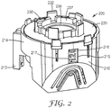
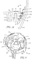
- FIG 2 is a perspective illustration of an exemplary dose counter in accordance with the present invention.
- the working components of the dose counter (200) are contained within a housing (210) and retained by a lid (220), where essentially just indicia (216) are visible via a window (215).
- the complete housing may be provided in a transparent material, such that the indicia may be viewed through the sidewall (214) of the dose counter housing.
- Such an exemplary dose counter is illustrated in Figure 3 to 8 , where the housing is made of a transparent material and no window is provided in the housing.
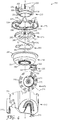
- Figures 3 and 4 represent exploded views from two different directions of a dose counter (200) orientated in respect to their position about the first axis (A) (the actuation axis).
- the dose counter (200) comprises an indicator member (270) and a worm (300).
- the dose counter may be mounted within the actuator such that the indicator member (270) faces towards the back so that indicia (216) provided on an indicium- or indicia-bearing surface (272) of the indicator member can be seen through the window (30) provided in the actuator.
- the indicator member (270) is constructed and arranged to undergo predetermined count-indicating motion when one or more doses are dispensed. It can be recognized that the indicator member (270) is rotatable about a second axis (271), wherein the second axis is disposed at an obtuse angle with respect to the first axis (A). The latter is best seen in Figure 6b showing a partial, vertical cross section through the exemplary dose counter showing the first and second axes (A and 271) and the obtuse angle ( ⁇ ).
- the first and second axes are disposed at an obtuse angle of 145 degrees or less relative to each other, in particular 135 degrees or less relative to each other, more particularly 125 degrees or less relative to each other, most particularly 120 degrees or less relative to each other.
- the first and second axes are favourably disposed at an obtuse angle of 95 degrees or greater relative to each other, more favourably 100 degrees or greater relative to each other, even more favourably 105 degrees or greater relative to each other, most favourably 110 degrees or greater relative to each other.
- the first and second axes intersect.
- an indicator member desirably comprises a indicium- or indicia-bearing surface, for e.g. indicating how many doses or how much medicament is contained in the container and/or how many doses or how much medicament has been dispensed from the container and/or that there is medicament still contained in the container that may be dispensed from the container and/or the container is or is considered empty.
- Indicia may be in the form of a sequence of numbers either increasing in value or decreasing in value around the indicator member.
- indicia may be colours. For example, a change of colour, for example from green to red, may be used to indicate the relative level of the medicament remaining in the container.
- an indication of the medicament status is sufficient; however the dose counter is still generally required to count each dose dispensed.
- Other indicia will be known to a person skilled in the art.
- an indicium- or indicia-bearing surface of the indicator member is desirably a conical or frustoconical surface relative to the second axis.
- the indicator member (270) has a series of indicia (216) disposed about the external frustoconical, indicia-bearing surface (272) in the form of numerals 200 in 20's down to zero (see e.g. Figure 4 ).
- the frustoconical, indicia-bearing surface (272) is arranged such that the portion of the surface carrying the indicia (216) is visible through a window (30) of an actuator (cf. Figure 1 ) and is orientated vertically so that the indicia may be viewed square on.
- the worm (300) typically includes a worm thread (304) and a central shaft (301).
- the worm is configured and arranged to drive the indicator member (270) as discussed in more detailed below.
- the worm is rotatable about a worm axis, labelled "W" in Figure 3 .
- a blind central hole (302) of the worm visible in e.g. Figure 4 ) engages a vertical post (219) extending from the floor of the housing (210), such that the worm is free to rotate about its vertical axis (W).
- Figure 6a shows how the worm is mounted within the housing on the post (219) that extends from a lower section (229) of the housing.
- Figures 6a and 6b providing partial, vertical cross sections through the dose counter ( Figure 6a with the worm but without the indicator member and Figure 6b without the worm but with the indicator member), it can be seen that the worm axis (W) and the second axis (271) are not disposed in a perpendicular alignment to each other.
- Figure 5b which provides a cut away view from above, it can be seen that the worm axis (W) and second axis (271) do not intersect.
- the worm and second axes are not co-axial, since the worm is arranged to drive the indicator member. While the worm and second axes could be parallel, for favourable functionality and optimal use of space, desirably they are not parallel to one another.
- the worm axis and first axis are not coaxial. Also it is desired that the worm axis does not intersect the first axis.
- the counter such that the worm axis is disposed from an angle of 180 degrees ("exact parallel alignment") to (and including) an angle of 160 degrees with respect to the first axis. It is more favourable (e.g. due to enhanced simplicity in design, assembly and manufacturing as well as operation) to dispose the worm axis in parallel alignment to the first axis. In regard to such more favoured embodiments it should be appreciated that because of e.g.
- the worm axis in a working, mass-produced dose counter may be deposited plus or minus three degrees from an exact parallel alignment to the first axis ("essentially parallel alignment"), and thus for this reason it will be understood that the general phrase "worm axis is disposed in parallel alignment to the first axis” includes “exactly parallel” as well as “essentially parallel” alignments.
- the worm axis (W) is parallel to the first axis (A), which will be appreciated from a study of any one of Figures 3 to 6a or Figure 8 .
- the vertical post (219) is positioned off-centre from the central hole (217) of the housing.
- the indicator member comprises a region for interaction with the worm, wherein the region of the indicator member and the worm are configured and arranged such that at least one portion of the region of the indicator member meshes with at least one portion of the thread of the worm. More desirably such a region of the indicator member is configured and arranged as a worm wheel.
- the inner surface (273) of the indicator member (270), i.e. the surface opposite the indicia-bearing surface (272) of the indicator member, includes protruding members (274) extending outwardly from the inner surface and arranged in a circular pattern forming a worm wheel.
- the protruding members are in the form of spokes (274) that are oblong shaped with chamfered edges.
- the spokes are desirably spaced apart sufficiently to allow the thread to pass between them and engage the lower surface (321 a) of a higher spoke (274a) and the upper surface (322b) of a lower spoke (274b) (see Figure 7e ).
- Protruding members may be any form suitable for engagement with a thread of a worm, e.g. in the form of spokes, ribs, posts, lugs, knobs, pins and the like.
- a worm wheel may be formed of protruding members extending radially outwardly.
- Worm wheels may be an integral component of an indicator member (e.g. as in the illustrated exemplary dose counter) or alternatively worm wheels may be a separate component appropriately directly affixed or indirectly coupled to an indicator member.
- the thread (304) of the worm (300) rises generally upwards when viewed from the top of the worm (300) and extends for greater than 360 degrees (more than one turn).
- a vertical overlap of the worm thread advantageously allows for permanent engagement with at least one protruding member (274) on the indicator member (270), because for at least a short part of the turn, two protruding members are engaged simultaneously.
- Such engagement is advantageous for a number of reasons including minimizing or preventing the indicator member (270) from rotating independently of a count and enhancing the precision of entry of an arriving protruding member due to secure (still engaged) positioning of a departing protruding member.
- a worm thread that extends greater than 360 degrees (i.e. has more than one turn), more particularly extends greater than 365 degrees, and most particularly extends greater than 375 degrees.
- the worm thread may have more than two turns, however it has been found advantageous for functionality and for ease of manufacturing to have two turns or less, in particular while having more than one turn.
- the cross-sectional radius of the worm from the worm axis to the outer edge of the worm flight desirably generally increases along the worm axis. This may be accomplished by generally increasing the cross-sectional diameter of the worm shaft along the worm axis or by generally increasing the cross-sectional width of the worm thread perpendicular to the worm axis along the worm axis or by both.
- the cross-sectional width of the worm thread (304) perpendicular to the worm axis (W) generally increases along the worm axis.
- the outer edge (305) has a trajectory in which the perpendicular distance from the worm axis (W) increases with increasing angle of turn and as the thread (304) rises towards the top of the worm (300).
- the cross-sectional radius of the worm from the worm axis to the outer edge of the worm flight generally increases along the worm axis.
- the trajectory/rate of increase of the outer edge of the flight may be an arc or linear with vertical distance.
- an arc is advantageous to allow for more precise tracking of protruding members associated with an indicator member; however in practice a linear rate of extension has also been found suitably accurate to provide sufficient tracking, both advantageously minimizing or preventing undesired wobbling of an indicator member due to excessive clearance between engaging portions/surfaces of the worm and indicator member.
- each complete (360 degree) turn of the worm (300) provides 15 degrees of rotation of the indicator member (270).
- the illustrated exemplary dose counters upon one count the worm rotates about 36 degrees and drives the indicator member about 1.5 degrees.
- worms are configured and arranged to undergo a predetermined rotational motion each time a dose is dispensed. Such rotational motion then drives the indicator member so that it achieves its predetermined count-indicating motion when one or more doses are dispensed.
- the indicator member may undergo a predetermined count-indicating motion each time a dose is dispensed or alternatively the indicator member undergo a predetermined count-indicating motion after a plurality of doses have been dispensed, for example after every five or every ten doses.
- Dose counters are desirably configured and arranged to induce the worm's predetermined rotational motion in coordination with reciprocal movement of the reciprocal actuation means (e.g. a valve) and the container.
- Exemplary dose counters illustrated in Figures 2 and 3 favourably include, in addition to the aforementioned components, a counter member (240), a count-transferring member (250), an indexing member (230), and a spring (260). As can be taken from e.g. Figures 3 and 4 , all of these components are oriented about the first axis (A).
- Exemplary dose counters also comprise a gear (303) provided coaxially (rotatable along the worm axis (W)) to the worm (300).
- the gear (303) is an integral portion formed at the top end of the central shaft (301) of the worm (300); however in alternative embodiments, the gear may be a separate component appropriately directly affixed or indirectly coupled to the worm.
- the counter member (240) as well as the count-transferring member (250) are desirably constructed and arranged to undergo predetermined counting or count-transferring motions, respectively, each time a dose is dispensed.
- the count member (240) induces (rotational or essentially rotational) movement of the count-transferring member (250), and the count-transferring member induces rotational movement of the worm (300) which in turn induces rotational movement of the indicator member (270).
- the counter member (240) is provided with at least four regions of interaction: a first with the count-transferring member; a second with ratchet member(s) provided on the lid; a third with the indexing member (in particular with saw-tooth protrusions thereof); and a fourth again with the ratchet member(s).
- the counter member is provided with two rings of upstanding teeth, an inner ring of teeth (241) and an outer ring of teeth (244), around a central cylinder (242) with a central hole (243).
- the outer ring of teeth (244) is disposed for interaction and engagement with ratchet members (224) provided on the bottom surface of the lid (220).
- the teeth of the outer teeth ring (244) comprise two regions for interaction: one region is a vertical surface (247) (i.e. the counter member's second region of interaction); the other region is an inclined surface (248) (i.e. the counter member's fourth region of interaction).
- An inner ring of teeth (241) is arranged for interaction and engagement with the saw-tooth protrusions (235) on the indexing member (230) (i.e. the counter member's third region of interaction) during the outward stroke of the indexing member, and favourably also during the return stroke of the indexing member of the illustrated embodiment.
- a circumferential perimeter (245) of the counter member (240) has a plurality of circumferentially equally spaced protrusions (246) extending outwards.
- the protrusions (246), representing the counter member's first region of interaction are arranged for engagement and interaction with the count-transferring member (250).
- the count-transferring member (250) is generally in the form of inner (251) and outer (252) coaxial cylinders, joined by an annular base (253).
- a plurality of bearing surfaces (218) are disposed on a shelf (211) (see Figure 8 ) in the housing (210), providing a low friction surface on which the count-transferring member rests and rotates.
- Vertical movement of the count-transferring member (250) is favourably limited or essentially prevented by inter alia how it is held within the housing of the dose counter.
- Figure 6a shows how the count-transferring member (250) is mounted within the housing (210).
- the counter member and the count-transferring member may be, independently, provided in various forms including rings, cylinders, disks or cones. It will also be appreciated that the two members may be nested.
- the inner cylinder (251) of the count-transferring member (250) has a diameter such that it slides axially inside the central cylinder (242) of the counter member (240).
- the outer cylinder (252) has a thin outer cylindrical surface (257).
- the outer circumferential perimeter (245) of the counter member (240) is slightly smaller in diameter than the internal surface (254) of the outer cylinder (252) of the count-transferring member (250), thus allowing axial (vertical) movement of the counter member (240) relative to the count-transferring member (250) and rotational movement of the counter member relative to the housing (210).
- the count-transferring member (250) includes a region for interaction and engagement with the counter member (240).
- the count-indicating member includes at least one channel (256) including a pair of inwardly facing ribs (255) on either side of a channel, and in particular four channels.
- the channels are arranged for engagement and interaction with the corresponding protrusions (246) of the counter member (240).
- the protrusions (246) extend outwardly, and engage the channels (256) of the count-transferring member (250).
- the protrusions (246) are a good fit in the channels (256) with little clearance.
- the channels are generally vertical, parallel to the first axis (A), and rotational or helical (vertical and rotational) movements of the count member will generally induce rotational movement of the count-transferring member. In such embodiments the count member and count-transferring member will generally rotate in tandem. In other alternative embodiments (not shown) the channels may be inclined, i.e. angled relative to the first axis (A). As described in detail in our copending application ( GB application No.
- the count-transferring member (250) includes a second region for interaction with the worm (300).
- the inner cylinder (251) of the count-transferring member (250) extends at its lower end (i.e. below the annular base (253)) into a horizontal and coaxial gear (280), which is thus rotatable about the first axis (A) (see e.g. Figure 4 ).
- the gear (280) is an integral portion of the count-transferring member; however in alternative embodiments the gear may be a separate component suitably directly affixed or indirectly coupled to the count-transferring member.
- the gear (280) of the count-transferring member (“first gear”) interacts and engages with the gear (303) coaxially affixed to the top end of worm (300) ("second gear"), so that rotation of the count-transferring member (250) is translated via the first and second gears (280, 303) into rotation of the worm (300).
- the rotation of the worm (300) in turn drives the indicator member (270) via interaction and engagement of the worm thread/flight and protruding members (274).
- Figure 5a shows a cut away isometric view vertically downwards into the housing (210) of the dose counter, showing the gear (280) of the count-transferring member (the member otherwise not being shown) and the gear (303) of the worm (300), but not showing the indicator member. It can be seen that teeth (324) of the first gear (280) engage teeth (325) of the second gear (303). The thread (304) of the worm is visible. Additionally, end-on views of the first axis (A) of the dose counter (200) and the worm axis (W) of the worm (300) are shown by intersection of crossed dashed lines.
- Figure 5b shows a different cut away isometric view vertically downwards into the housing (210) of the dose counter, showing inter alia teeth (324) of the first gear (280) engaging teeth (325) of the second gear (303) and a portion of the worm thread (304) engaging at least one (274a) of the protruding members (274) on the internal surface (273) of the indicator member (270).
- the axis (271) of the indicator member (270) is shown to intersect the first axis (A); although in this view the angle between the two axes in the vertical plane is not visible.
- the lid (220) is generally annular with a central circular hole (221).
- the hole has a plurality of circumferentially equally spaced radial hole extensions (222) of slightly greater radius and a plurality of circumferentially equally spaced small radially inward protrusions (223).
- Around the central hole (221) on the bottom surface of the lid (220) are a plurality of ratchet members (224), comprising two regions for engagement and interaction with the counter member (240); one region is a vertical surface (225) and the other region is an inclined surface (226).
- Disposed around the outer circumferential edge (227) of the lid (220) are a plurality of protrusions (228) that provide a means of correctly orientating and securing the lid (220) to the housing (210).
- the indexing member (230) is shaped generally like a cylindrical cap with a central hole (231).
- the indexing member (230) has a plurality of peripheral castellations (232) that are designed to pass through the radial hole extensions (222) of the lid (220).
- the indexing member (230) also has a plurality of peripheral grooves (233) designed to accommodate the inward protrusions (223) of the lid (220). The combination of these features allows for axial (vertical) movement of the indexing member relative to the lid, while securing the indexing member within the dose counter.
- a plurality of circumferentially equally spaced saw-tooth projections (235) are provided for interaction with the inner ring of teeth (241) on the counter member (240).
- the upper portion of the indexing member includes a castellation-bearing wall (237) and a circumferential ridge (236) that defines a sunken, cylindrical space.
- the spring (260) that provides a biasing means can be in the form of an annular leaf spring.
- the leaf spring (260) has an annular ring (261) with a plurality of spring elements (262) or leaves extending generally helically (coaxially with the ring) from radial projections on the circumference of the ring.
- the inner circumferential edge (263) of the leaf spring (260) is slightly larger in diameter than the outer surface (258) of the inner cylinder (251) of the count-transferring member (250) such that the bottom surface of the leaf spring (260) engages with the top surface (259) of the annular base (253) of the count-transferring member (250).
- the spring elements (262) are biased upwardly from the leaf spring (260) such that they engage with the bottom surface of the counter member (240).
- the leaf spring (260) thus biases the counter member (240) axially away from the annular base (253) of the count-transferring member (250) and towards the saw-tooth projections (235) on the indexing member (230) and towards the ratchet members (224).
- the outer ring of teeth (244) is biased towards the ratchet members (224) and the inner ring of teeth (241) is biased towards the saw-tooth projections (235).
- the pair of such that engage at any stage of operation is determined by the relative rotational positions of the indexing member (230) and the counter member (240).
- the dose counter housing (210) has a generally cylindrical body with a plurality of clip features (212) to engage with the protrusions (228) of the lid (220) to provide a means of securing the lid (220) to the housing (210).
- Two forward legs (213) are provided for engagement of the dose counter (200) with an interior surface of an actuator (e.g. an actuator of the type illustrated in Figure 1 ).
- the sidewall (214) of the housing of the embodiment shown in Figure 3 is made of a transparent material.
- Figure 8 shows a view into the housing of the dose counter (200) shown in Figure 3 .
- the dose counter (200) may be assembled by inserting the indicator member (270) into the tapering housing section of the housing (210).
- the worm (300) is dropped onto the vertical post (219).
- the count-transferring member (250) is then inserted and seated on a shelf (211) of the housing (210).
- the count-transferring member is located above the indicator member (270) and the gear (280) of the counter-transferring member engages the gear (303) of the worm (300).
- the leaf spring (260), counter member (240) and indexing member (230) can then be assembled in order over the count-transferring member (250), and finally the lid (220) can be fitted about the peripheral castellations (232) of the indexing member (230).
- the lid (220) is snap-fit engaged with the dose counter housing (210) by engagement of the protrusions (228) and associated clip features (212).
- the lid (220) and housing (210) may be otherwise connected together, such as by press fit connections, or may be ultrasonically or otherwise welded together.
- Exemplary dose counters illustrated in Figures 2 and 3 are particularly suitable for use in an actuator of a pressurized metered dose inhaler.
- dose counters (200) of Figures 2 and 3 may be suitably mounted within the interior of the actuator (20) generally positioned beneath the container (16) near and around the nozzle block (21) of the actuator.
- the castellations (232) of the indexing member (230) may surround the ferrule (18).
- the ferrule may then be located within the sunken, cylindrical area defined within the castellation bearing wall (237) (see Figure 2 ) and circumferential ridge (236).
- the legs (213; one visible in Figure 2 ) of the dose counter (200) may suitably engage with the bottom floor (32) of the actuator (20).
- a dose counter such as one illustrated in Figure 2 or Figure 3 with a pressurized metered dose inhaler such as that shown in Figure 1 can be described in the following - in two parts (1) the movements of the counter member and count-transferring member and (2) the movements of the worm and indicator member:
- the vertical surfaces (225) of the ratchet members (224) disposed on the bottom surface of the lid (220) are engaged with the vertical surfaces (247) of the outer ring of teeth (244) on the counter member (240).
- the protrusions (246) on the outer perimeter of the counter member (240) are engaged with the channels (256) on the interior side of the outer cylinder (252) of the count-transferring member (250).
- the leaf spring (260) additionally urges the counter member to its uppermost vertical position. Engagement of the aforementioned regions together with the bias provided by the dose counter spring prevents the counter member and count-transferring member from undergoing any rotational movement during storage and handling.
- the ferrule (18) may be resting on the circumferential ridge (236) of the indexing member (230) or the ferrule (18) may rest clear of the indexing member (230).
- the saw tooth projections (235) of the indexing member may be resting on the inner ring teeth (241) of the counter member (240).
- the downward vertical movement of the aerosol container towards the nozzle block (21) causes the ferrule (18) to engage (if it has not already done so) and then push down on the circumferential ridge (236) of the indexing member (230), thus causing a downward vertical movement of the indexing member and thus initiating the outward stroke of the indexing member.
- the saw-tooth projections (235) of the indexing member (230) engage (if they have not already done so) and push down on the inner ring teeth (241) of the counter member (240).
- the counter member (240) will continue to move (essentially) vertically downwards until the ratchet member (224) disengages from the counter member (240). However if the user relieves his force on the container before disengagement from the ratchet member, the counter member (240) will return to the first rest position, and no dose count will be recorded.
- the indexing member (230) and counter member (240) continue to move downwardly until such time as the counter member's outer teeth (244) disengage from the ratchet members (224) (in particular until the vertical surfaces of each (247 and 225, respectively) disengage).
- a dose count is committed to and is therefore non-reversible.
- the counter member is free to rotate and will rotate under the force of the bias. If applicable (i.e. if the user continues to press down on the container to complete actuation of the inhaler), the counter member will also continue to move vertically downward under the force of the user via the indexing member.
- the regions of interaction of the indexing member (230) and the counter member (240) include the saw-tooth projections (235) of the indexing member (230) and the inner teeth ring (241) of the counter member (240).
- the angular surfaces of said regions (235 and 241) are configured and arranged such that when force is applied by a bias, e.g. the leaf spring (260), the regions are urged vertically towards each other and since the indexing member (230) cannot rotate, the interaction between the saw-tooth projections (235) and inner teeth ring (241) now causes the counter member (240) to rotate.
- the count-transferring member rotates essentially in tandem with the rotational movement of the counter member.
- the counter member may simultaneously move vertically, so that the movement in total is an essentially helical movement; however it is generally the rotational component that induces the rotational movement of the count-transferring member.
- the point of no return for a dose counter is typically purposely set to be earlier than that of the dispenser, so that there is normally a tendency to over-count rather than under-count. Accordingly typically after the point of no return for a dose counter, the user typically still needs to apply some more force on the container to cause actuation of the inhaler.
- the patient will typically continue to apply force to the aerosol container (16) until a metered dose is released. Typically this will occur shortly after the disengagement described above, to ensure that the dose count has been committed to prior to releasing medicament and hence minimizing any potential to under-count administered doses.
- the user may (and most often does) continue to apply force onto the aerosol container, thus inducing a continued outward stroke of the indexing member (230). This movement is however generally not necessary for the dose counter to complete its counting motion.
- the counter member (240) can move vertically downwards until the protrusions (246) of the counter member reach the bottoms of the channels (256) of the count-transferring member (250).
- the force on the indexing member is released and the valve ferrule (18) is biased upwards away from the indexing member by the spring (24) in the valve, so the indexing member is allowed to commence its return stroke.
- the counter member (240) is urged, under the force of the leaf spring (260), vertically upwards towards the ratchet member (224), thereby moving the indexing member (230) vertically upwards.
- the inclined surfaces (226) of the ratchet members (224) and the inclined surfaces (248) of the outer ring of teeth (244) of the counter member (240) engage.
- the two sets of inclined surfaces (226, 248) are configured and arranged such that as the counter member (240) undergoes a further vertically upward movement under the resultant force of the leaf spring (260), the engagement and sliding of said inclined surfaces of the counter member over the inclined surfaces of the fixed ratchet members (224) induces further rotational movement of the counter member (240), which in turns induces a further rotational movement of the count-transferring member.
- the last rotational movement of the counter member allows for completion of its predetermined counting motion.
- each saw-tooth projection (235) moves over a tooth of the inner set of teeth (241) when they are vertically clear to do so under the bias of the interaction between the two sets of inclined surfaces (226, 248).
- the indexing member (230), leaf spring (260) and counter member (240) return to a second rest position where each set of teeth (241, 244) of the counter member has been incremented by one tooth and the count-transferring member (250) has rotated an increment corresponding to one count (and where accordingly the first gear (280) associated with the count-transferring member (250) has also been incremented by one tooth).
- the operation of the worm and indicator member is linked to the operation described above, in particular to the rotation of the count-transferring member via the first and second gears (280, 303).
- the operation of the indexing member (230), the counter member (240) and the spring (260) of the dose counter (200) drives the count-transferring member (250) in rotational increments, which are in a clockwise direction when viewed from above.
- the first gear (280) of the count-transferring member (250) typically has 20 teeth (see e.g. Figure 5a or b ), and consequently it makes a complete rotation (which is clockwise) after 20 counts, where each tooth corresponds to a count of one dose.
- the second gear (303) of the worm (300) typically has 10 teeth (see e.g. Figure 5a or b ), and consequently it makes a complete rotation (which is anticlockwise) after 10 counts, where again each tooth corresponds to a count of one dose.
- the gear ratio of the first gear to the second gear is therefore 2 to 1 (20 to 10 teeth).
- the worms of each the illustrated exemplary dose counter moves 36° per count, rotating the indicator member about 1.5 degrees.
- the gear ratio of the worm's rotation to the indicator member's rotation is therefore 24 to 1 (36 degrees to 1.5 degrees). Relative to the orientation shown in Figure 5 , the worm turns anticlockwise and the indicator member turns clockwise.
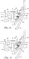
- Figure 7a is a representation of a first rest position prior to a count and Figure 7b is a representation of a second rest position after one single count, i.e. where the worm has rotated 36 degrees and the indicator member about 1.5 degrees.
- indicator member protruding member labelled "274a” is hatched.
- Figure 7a the (vertical face of the) upper terminating end (307) of the thread (304) can be seen (to the right), and a portion near this end is engaged with a protruding member (274z) of the indicator member.
- the thread desirably turns approximately 367°, and the portion of the thread near to the other, lower, terminating end (306) of the thread is engaged with the protruding member (274a) following the protruding member (274z) engaged by the portion near the upper terminating end (307).
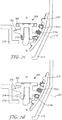
- Figure 7c illustrates the position when the worm has rotated 90 degrees (between two and three counts); Figure 7d , 180 degrees (five counts); Figure 7e , 270 degrees (between seven and eight counts); Figure 7f , 350 degrees (almost ten counts); Figure 7g , 360 degrees (tens counts).
- the second and worm axes are not in a perpendicular alignment relative to each other.
- the second axis may be favourably disposed at an obtuse angle with the respect to the worm axis, more favourably they are disposed at an obtuse angle of 95 degrees or greater relative to each other, even more favourably 100 degrees or greater relative to each other, yet even more favourably 105 degrees or greater relative to each other, most favourably 110 degrees or greater relative to each other.
- the second and worm axes are favourably disposed at an obtuse angle of 145 degrees or less relative to each other, more favourably 135 degrees or less relative to each other, even more favourably 125 degrees or less relative to each other, most favourably120 degrees or less relative to each other.
- the configuration and/or the positioning of the worm (in particular the thread thereof) and/or of the protruding members of the indicator member so that the worm thread provides a near-tangential (relative to the second axis) torque against the protruding member(s).
- the thread of the worm in five sections differing in slope, in particular the sections bordering the two ends are generally horizontal, connected to two generally rising sections with a central generally horizontal section.
- a stop feature (275, shown in Figure 4 ) on the indicator member comes into contact with a similar feature (329, shown in Figure 8 ) on the inside of the housing.
- a similar stop feature is described in WO 2007/124406 .
- An alternative mechanism to stop an indicator member of a dose counter advancing beyond zero involves stalling or jamming the worm thread. This can be achieved by either having no protruding member(s) after the final driven protruding member (e.g. providing a gap of a width sufficient to extend to where at least the next protruding member would otherwise have been), or alternatively having a continuous surface rather than a gap between the final driven protruding member and the following protruding member that should not be picked up but would be picked up if the device were to continue. Where a gap is provided the worm flight would cease to drive the indicator member, which would remain in position with a display of zero.
- actuation of the actuation means would still be possible.
- the worm would jam into the indicator member and prevent any rotation. This would only jam the indicator member, worm, counter member and count-transferring member, whilst translation of the indexing member would be possible and thus actuation of the actuation means (e.g. valve) would still be possible.
- a dose counter is described with reference to a pressurized metered dose inhaler.
- the dose counter may be adapted for use with other actuators, dispensers or inhalers having a reciprocal actuation means, for example, nasal pressurized metered dose devices, dry powder inhalers or pump spray devices.
- Dose counters are generally constructed from plastic components to keep the cost and weight of the dose counter to a minimum whilst maximising its strength and reliability.
- biasing elements which as mentioned supra may be a spring, for example, a coil spring or a leaf spring
- a spring for example, a coil spring or a leaf spring
- metallic materials that resist corrosion and/or oxidation are desirably chosen.
Landscapes
- Health & Medical Sciences (AREA)
- Engineering & Computer Science (AREA)
- Life Sciences & Earth Sciences (AREA)
- Pulmonology (AREA)
- Biomedical Technology (AREA)
- Veterinary Medicine (AREA)
- Public Health (AREA)
- Bioinformatics & Cheminformatics (AREA)
- General Health & Medical Sciences (AREA)
- Anesthesiology (AREA)
- Animal Behavior & Ethology (AREA)
- Heart & Thoracic Surgery (AREA)
- Hematology (AREA)
- Theoretical Computer Science (AREA)
- Physics & Mathematics (AREA)
- General Physics & Mathematics (AREA)
- Biophysics (AREA)
- Containers And Packaging Bodies Having A Special Means To Remove Contents (AREA)
- Infusion, Injection, And Reservoir Apparatuses (AREA)
Claims (24)
- Dosiszähler (200) zur Verwendung mit einem Inhalator (5), umfassend einen Behälter für Medikament (15), ausgestattet mit einem hin- und herlaufenden Betätigungselement (17) zur Abgabe einer Medikamentendosis daraus, wobei hin- und herlaufendes Betätigungselement sich an einer ersten Achse (A) entlang bewegt, wobei der Dosiszähler Folgendes umfasst:ein Anzeigeelement (270), drehbar über eine zweite Achse (271), wobei das Anzeigeelement so aufgebaut und angeordnet ist, dass eine vorbestimmte Zählerbewegung ausgelöst werden kann,wenn eine oder mehrere Dosen ausgegeben werden, wobei die zweite Achse (271) in einem stumpfen Winkel (α) im Verhältnis zur ersten Achse (A) angeordnet ist, unddadurch gekennzeichnet, dassder Dosiszähler ferner ein Gewinde (300) umfasst, rotierbar über eine Schneckenachse (W),wobei das Schneckengewinde aus einer Schneckenwelle (301) und einem Schneckengang (304) besteht und so angeordnet ist, dass es das Anzeigeelement (270) antreiben kann, undwobei die Schneckenachse (W) und die zweite Achse (271) sich nicht überschneiden und in einem stumpfen Winkel (β) von 95 Grad oder mehr im Verhältnis zueinander angeordnet sind.
- Dosiszähler nach Anspruch 1, wobei die erste (A) und zweite Achse (271) sich überschneiden.
- Dosiszähler nach einer der vorstehenden Ansprüche, wobei die erste Achse (A) und die Schneckenachse (W) sich nicht überschneiden.
- Dosiszähler nach einem der vorstehenden Ansprüche, wobei die Schneckenachse (W) und die erste Achse (A) nicht in einer koaxialen Ausrichtung im Verhältnis zueinander angeordnet sind.
- Dosiszähler nach einem der vorstehenden Ansprüche, wobei die Schneckenachse (W) in einem Winkel von 180 Grad bis zu einem stumpfen Winkel von 160 Grad im Verhältnis zur ersten Achse (A) angeordnet ist.
- Dosiszähler nach Anspruch 5, wobei die Schneckenachse (W) in paralleler Ausrichtung zur ersten Achse (A) angeordnet ist.
- Dosiszähler nach einem der vorstehenden Ansprüche, wobei das Anzeigeelement (270) aus einem Übertragungsbereich (274) mit dem Gewinde (300) zusammengesetzt ist, und wobei der Bereich des Anzeigeelements und des Gewindes so konfiguriert und angeordnet sind, dass mindestens ein Teil des Bereichs des Anzeigeelements mit mindestens einem Teil des Gewindes (304) an der Schnecke interagiert.
- Dosiszähler nach Anspruch 7, wobei der Bereich des Anzeigeelements (274) wie ein Gewinderad konfiguriert und angeordnet ist.
- Dosiszähler nach einem der vorstehenden Ansprüche, wobei im Verhältnis zum Winkel zwischen Schneckenachse (W) und zweiter Achse (271), der Querschnittsradius des Gewindes (300) vom Schneckengewinde bis zur äußeren Kante (305) des Schneckengewindes (304) entlang der Gewindeachse im Allgemeinen ansteigt.
- Dosiszähler nach Anspruch 9, wobei der Querschnittsradius der Gewindeschnecke (301) entlang der Schneckenachse im Allgemeinen ansteigt.
- Dosiszähler nach den Ansprüchen 9 oder 10, wobei die Querschnittsbreite des Schneckengewindes (304) senkrecht zur Schneckenachse im Allgemeinen entlang der Gewindeachse ansteigt.
- Dosiszähler nach einer der vorstehenden Ansprüche, wobei das Schneckengewinde (304) mehr als eine Windung aufweist.
- Dosiszähler nach Anspruch 12, wobei das Schneckengewinde (304) weniger als zwei Windungen aufweist.
- Dosiszähler nach einem der vorstehenden Ansprüche, wobei das Anzeigeelement (270) aus einer Zeichen tragenden Oberfläche (272) besteht, für die Anzeige der Anzahl der Dosen oder Medikamentenmenge, die in dem Behälter enthalten ist und/oder wie viele Dosen oder welche Medikamentenmenge aus dem Behälter entnommen wurden.
- Dosiszähler nach Anspruch 14, wobei die Zeichen tragende Oberfläche (272) eine konische oder kegelstumpfförmige Oberfläche im Verhältnis zur zweiten Achse (271) ist.
- Dosiszähler nach einem der vorstehenden Ansprüche, wobei die erste (A) und zweite (271) Achse in einem stumpfen Winkel von 95 Grad oder größer im Verhältnis zueinander angeordnet sind.
- Dosiszähler nach einem der vorstehenden Ansprüche, wobei die erste (A) und zweite Achse (271) in einem stumpfen Winkel von 145 Grad oder weniger im Verhältnis zueinander angeordnet sind.
- Dosiszähler nach einem der vorstehenden Ansprüche, wobei die zweite Achse (271) und die Wurmachse (W) in einem stumpfen Winkel von 145 Grad oder weniger im Verhältnis zueinander angeordnet sind.
- Aktuator (20) für die Verwendung mit einem Dispenser oder als Teil eines Dispensers, wobei der Aktuator einen Dosiszähler (200) nach einem der Ansprüche 1 bis 18 umfasst.
- Aktuator nach Anspruch 19, wobei der Dosiszähler (200) im Inneren des Aktuators (20) montiert ist.
- Aktuator nach Anspruch 19 oder Anspruch 20, wobei der Aktuator (20) ein Aktuator für die Verwendung zusammen mit einem Behälter (15) ist, einschließlich Aerosoldose (16), und einem Dosierventil (17), und wobei der Dosiszähler (200) im Inneren des Aktuators installiert ist, so dass der Dosiszähler bei Verwendung im Allgemeinen unter dem Behälter nahe des und/oder rund um einen Düsenblock (21) des Aktuators positioniert ist.
- Aktuator nach Anspruch 19 oder 20, wobei der Aktuator (20) ein Aktuator für die Verwendung mit einem Behälter (15), einschließlich eines Aerosolbehälters (16), ist, und einem Messventil (17), ausgestattet mit einem Eintauchschlauch, und wobei der Dosiszähler im Inneren des Aktuators installiert ist, so dass der Dosiszähler bei Verwendung im Allgemeinen über dem Behälter nahe des und/oder rund um einen Düsenblock/ (21) des Aktuators positioniert ist.
- Dispenser, einen Dosiszähler (200) nach einem der Ansprüche 1 bis 18 oder einen Aktuator (20) nach einem der Ansprüche 19 bis 22 umfassend.
- Dispenser nach Anspruch 23, wobei der Dispenser ein Treibgas-Dosieraerosol-Inhalator (5) ist.
Priority Applications (1)
| Application Number | Priority Date | Filing Date | Title |
|---|---|---|---|
| PL10790498T PL2509666T3 (pl) | 2009-12-09 | 2010-12-06 | Wskaźnik dawki |
Applications Claiming Priority (2)
| Application Number | Priority Date | Filing Date | Title |
|---|---|---|---|
| GBGB0921555.9A GB0921555D0 (en) | 2009-12-09 | 2009-12-09 | Dose indicator |
| PCT/US2010/059019 WO2011071788A1 (en) | 2009-12-09 | 2010-12-06 | Dose indicator |
Publications (2)
| Publication Number | Publication Date |
|---|---|
| EP2509666A1 EP2509666A1 (de) | 2012-10-17 |
| EP2509666B1 true EP2509666B1 (de) | 2017-05-17 |
Family
ID=41666844
Family Applications (1)
| Application Number | Title | Priority Date | Filing Date |
|---|---|---|---|
| EP10790498.9A Active EP2509666B1 (de) | 2009-12-09 | 2010-12-06 | Dosisindikator |
Country Status (9)
| Country | Link |
|---|---|
| US (1) | US8814035B2 (de) |
| EP (1) | EP2509666B1 (de) |
| JP (2) | JP6114033B2 (de) |
| CN (1) | CN102652026B (de) |
| CA (1) | CA2783560C (de) |
| ES (1) | ES2634467T3 (de) |
| GB (1) | GB0921555D0 (de) |
| PL (1) | PL2509666T3 (de) |
| WO (1) | WO2011071788A1 (de) |
Families Citing this family (34)
| Publication number | Priority date | Publication date | Assignee | Title |
|---|---|---|---|---|
| EP2010125B1 (de) * | 2006-04-21 | 2017-01-04 | 3M Innovative Properties Company | Dosiszähler |
| GB0920499D0 (en) | 2009-11-23 | 2010-01-06 | 3M Innovative Properties Co | Dose counter |
| CN104203319B (zh) * | 2012-01-23 | 2017-03-08 | 赛诺菲股份有限公司 | 用于吸入装置的剂量计数机构和吸入装置 |
| US20150306322A9 (en) * | 2012-01-23 | 2015-10-29 | Sanofi Sa | Inhalation Device |
| GB201215917D0 (en) | 2012-09-06 | 2012-10-24 | 3M Innovative Properties Co | Improvements in or relating to dose indicators |
| GB201223008D0 (en) * | 2012-12-20 | 2013-01-30 | Euro Celtique Sa | Counter |
| GB201312448D0 (en) | 2013-07-11 | 2013-08-28 | 3M Innovative Properties Co | Dose indicator or dose counter |
| GB201322677D0 (en) * | 2013-12-20 | 2014-02-05 | 3M Innovative Properties Co | Actuator for an inhaler |
| GB201406046D0 (en) | 2014-04-03 | 2014-05-21 | 3M Innovative Properties Co | Dose indicator or dose counter |
| GB201406047D0 (en) * | 2014-04-03 | 2014-05-21 | 3M Innovative Properties Co | Dose indicator or dose counter |
| TW201636068A (zh) * | 2015-01-13 | 2016-10-16 | 賽諾菲股份有限公司 | 藥物輸送裝置之組件 |
| EP3368083A1 (de) | 2015-10-29 | 2018-09-05 | 3M Innovative Properties Company | Formulierung und aerosoldosen, inhalatoren und dergleichen mit der formulierung |
| US20170361036A1 (en) * | 2016-06-15 | 2017-12-21 | Virgilant Technologies Limited | Electronic inhaling device |
| EP3300753B1 (de) | 2016-09-30 | 2018-12-12 | Presspart Gmbh & Co. Kg | Dosierinhalator zur abgabe von dosen eines aerosols |
| ES2913089T3 (es) | 2017-02-20 | 2022-05-31 | Presspart Gmbh & Co Kg | Inhalador dosificador |
| GB201706505D0 (en) | 2017-04-25 | 2017-06-07 | 3M Innovative Properties Co | Medicinal inhaler drive mechanism |
| US11207477B2 (en) | 2017-05-17 | 2021-12-28 | Kindeva Drug Delivery L.P. | Formulation and aerosol canisters, inhalers, and the like containing the formulation |
| USD882754S1 (en) | 2017-12-20 | 2020-04-28 | Presspart Gmbh & Co. Kg | Inhaler |
| WO2019236397A1 (en) | 2018-06-07 | 2019-12-12 | 3M Innovative Properties Company | Fluticasone and vilanterol formulation and inhaler |
| JP2021527057A (ja) | 2018-06-07 | 2021-10-11 | キンデーバ ドラッグ デリバリー リミティド パートナーシップ | フルチカゾン及びビランテロール製剤並びに吸入器 |
| EP3880169A1 (de) | 2018-11-12 | 2021-09-22 | Kindeva Drug Delivery L.P. | Umeclidinium- und vilanterolformulierung und inhalator |
| EP3940677A1 (de) | 2020-07-17 | 2022-01-19 | Presspart Gmbh & Co. Kg | Medikamentenbehälter und medikamentenabgabevorrichtung |
| CN111860750B (zh) * | 2020-08-24 | 2022-06-21 | 万通(苏州)定量阀系统有限公司 | 一种气雾剂阀门计数指示器 |
| US12029562B2 (en) | 2021-04-14 | 2024-07-09 | Satio, Inc. | Dermal patch system |
| US11964121B2 (en) | 2021-10-13 | 2024-04-23 | Satio, Inc. | Mono dose dermal patch for pharmaceutical delivery |
| US12023156B2 (en) | 2021-10-13 | 2024-07-02 | Satio, Inc. | Dermal patch for collecting a physiological sample |
| US12048543B2 (en) | 2021-11-08 | 2024-07-30 | Satio, Inc. | Dermal patch for collecting a physiological sample with removable vial |
| US11877848B2 (en) | 2021-11-08 | 2024-01-23 | Satio, Inc. | Dermal patch for collecting a physiological sample |
| US12053284B2 (en) | 2021-11-08 | 2024-08-06 | Satio, Inc. | Dermal patch for collecting a physiological sample |
| EP4398879A1 (de) | 2021-09-08 | 2024-07-17 | Kindeva Drug Delivery L.P. | Dosierinhalatoren und lösungszusammensetzungen |
| WO2024181972A1 (en) | 2022-03-01 | 2024-09-06 | Kindeva Drug Delivery L.P. | Metered dose inhalers and high-dose suspensions |
| GB2621335B (en) * | 2022-08-08 | 2024-09-04 | Merxin Ltd | Dose counter |
| WO2024182699A1 (en) | 2023-03-02 | 2024-09-06 | Kindeva Drug Delivery L.P. | Metered dose inhalers and solutions including cannabinoids in hfo-1234ze(e) |
| WO2024182686A1 (en) | 2023-03-02 | 2024-09-06 | Kindeva Drug Delivery L.P. | Metered dose inhalers and solutions including cannabinoids in hfa-152a |
Family Cites Families (24)
| Publication number | Priority date | Publication date | Assignee | Title |
|---|---|---|---|---|
| JPS6238291Y2 (de) * | 1979-10-25 | 1987-09-30 | ||
| GB9025654D0 (en) | 1990-11-26 | 1991-01-09 | Riker Laboratories Inc | Device |
| GB9211436D0 (en) | 1992-05-29 | 1992-07-15 | Norton Healthcare Ltd | Dose indicating device |
| JP3308425B2 (ja) * | 1995-03-10 | 2002-07-29 | 株式会社ユニシアジェックス | 鼻腔用投薬器 |
| US5871007A (en) | 1997-06-09 | 1999-02-16 | Chase Marketing International L.L.C. | Throat spray counting mechanism |
| TW533865U (en) | 1997-06-10 | 2003-05-21 | Glaxo Group Ltd | Dispenser for dispensing medicament and actuation indicating device |
| DE69918267T2 (de) | 1998-01-16 | 2005-07-28 | 1263152 Ontario Inc., London | Anzeigevorrichtung zur verwendung mit einer abgabevorrichtung |
| US6082358A (en) * | 1998-05-05 | 2000-07-04 | 1263152 Ontario Inc. | Indicating device for aerosol container |
| DE29814647U1 (de) | 1998-08-14 | 1999-12-23 | Josef Wischerath Gmbh & Co. Kg, 50259 Pulheim | Inhalator mit einer Dosierzähleinrichtung |
| GB2348928B (en) | 1999-04-07 | 2001-10-31 | Bespak Plc | Improvements in or relating to dispensing apparatus |
| GB2385640B (en) | 2001-02-23 | 2003-10-15 | Bespak Plc | Dosage counting devices |
| JP2003295274A (ja) * | 2002-03-29 | 2003-10-15 | Fuji Photo Optical Co Ltd | ウォームギア装置及びカメラ |
| GB0209531D0 (en) * | 2002-04-26 | 2002-06-05 | Glaxo Group Ltd | Medicament dispenser |
| ES2321601T3 (es) * | 2002-06-21 | 2009-06-09 | Glaxo Group Limited | Indicador de accionamiento para dispositivo distrituidor. |
| WO2004041334A2 (en) | 2002-11-04 | 2004-05-21 | Bang & Olufsen Medicom A/S | Device for dispension |
| GB0328635D0 (en) | 2003-12-10 | 2004-01-14 | 3M Innovative Properties Co | Dose counter for dispensers |
| CA2555347A1 (en) * | 2004-02-16 | 2005-09-01 | Stephen Edward Augustyn | Counter for use with a medicament dispenser |
| WO2006062450A1 (en) | 2004-12-10 | 2006-06-15 | Ernst Hörlins Ingenjösbyra Ab | Dose indicator for a dose inhaler |
| EP2010125B1 (de) * | 2006-04-21 | 2017-01-04 | 3M Innovative Properties Company | Dosiszähler |
| CA2661132A1 (en) * | 2006-08-22 | 2008-02-28 | Glaxo Group Limited | Drug dispenser |
| DE102006049614A1 (de) * | 2006-10-20 | 2008-04-24 | Rpc Formatec Gmbh | Inhalier-Gerät |
| GB0706405D0 (en) * | 2007-04-02 | 2007-05-09 | 3M Innovative Properties Co | Dose counter |
| DE102007045438B4 (de) | 2007-09-22 | 2016-09-01 | Boehringer Ingelheim International Gmbh | Inhalier-Gerät |
| GB0920499D0 (en) | 2009-11-23 | 2010-01-06 | 3M Innovative Properties Co | Dose counter |
-
2009
- 2009-12-09 GB GBGB0921555.9A patent/GB0921555D0/en not_active Ceased
-
2010
- 2010-12-06 EP EP10790498.9A patent/EP2509666B1/de active Active
- 2010-12-06 JP JP2012543175A patent/JP6114033B2/ja active Active
- 2010-12-06 US US13/514,192 patent/US8814035B2/en active Active
- 2010-12-06 PL PL10790498T patent/PL2509666T3/pl unknown
- 2010-12-06 CA CA2783560A patent/CA2783560C/en active Active
- 2010-12-06 WO PCT/US2010/059019 patent/WO2011071788A1/en active Application Filing
- 2010-12-06 CN CN201080056146.8A patent/CN102652026B/zh active Active
- 2010-12-06 ES ES10790498.9T patent/ES2634467T3/es active Active
-
2015
- 2015-10-09 JP JP2015200664A patent/JP6141939B2/ja active Active
Also Published As
| Publication number | Publication date |
|---|---|
| ES2634467T3 (es) | 2017-09-27 |
| CA2783560A1 (en) | 2011-06-16 |
| WO2011071788A1 (en) | 2011-06-16 |
| GB0921555D0 (en) | 2010-01-27 |
| PL2509666T3 (pl) | 2017-10-31 |
| CN102652026A (zh) | 2012-08-29 |
| EP2509666A1 (de) | 2012-10-17 |
| JP2013513431A (ja) | 2013-04-22 |
| JP2016027894A (ja) | 2016-02-25 |
| JP6141939B2 (ja) | 2017-06-07 |
| CN102652026B (zh) | 2014-08-20 |
| US8814035B2 (en) | 2014-08-26 |
| JP6114033B2 (ja) | 2017-04-12 |
| CA2783560C (en) | 2017-05-23 |
| US20120241527A1 (en) | 2012-09-27 |
Similar Documents
| Publication | Publication Date | Title |
|---|---|---|
| EP2509666B1 (de) | Dosisindikator | |
| EP2504797B2 (de) | Dosiszähler | |
| EP2108395B1 (de) | Vorrichtung zur Abgabe von Aerosol | |
| EP1927073B1 (de) | Mechanischer dosiseinheitenzähler für einen trockenpulverinhalator | |
| US7407066B2 (en) | Dosage counting devices | |
| JP6495263B2 (ja) | 投与量インジケータ又は投与量カウンタ | |
| EP3127048B1 (de) | Dosisindikator für inhalator mit abgemessener dosis | |
| EP3127049B1 (de) | Dosenzähler für inhalator mit abgemessener dosis | |
| US20040149773A1 (en) | Dosage counting devices | |
| GB2522664A (en) | Dose counter and dispensing apparatus | |
| CA3153565A1 (en) | Event status apparatuses and related devices, systems, and methods | |
| WO2020163463A9 (en) | Dose feedback mechanisms and assemblies for user feedback |
Legal Events
| Date | Code | Title | Description |
|---|---|---|---|
| PUAI | Public reference made under article 153(3) epc to a published international application that has entered the european phase |
Free format text: ORIGINAL CODE: 0009012 |
|
| 17P | Request for examination filed |
Effective date: 20120620 |
|
| AK | Designated contracting states |
Kind code of ref document: A1 Designated state(s): AL AT BE BG CH CY CZ DE DK EE ES FI FR GB GR HR HU IE IS IT LI LT LU LV MC MK MT NL NO PL PT RO RS SE SI SK SM TR |
|
| DAX | Request for extension of the european patent (deleted) | ||
| 17Q | First examination report despatched |
Effective date: 20141120 |
|
| GRAP | Despatch of communication of intention to grant a patent |
Free format text: ORIGINAL CODE: EPIDOSNIGR1 |
|
| STAA | Information on the status of an ep patent application or granted ep patent |
Free format text: STATUS: GRANT OF PATENT IS INTENDED |
|
| INTG | Intention to grant announced |
Effective date: 20170125 |
|
| GRAS | Grant fee paid |
Free format text: ORIGINAL CODE: EPIDOSNIGR3 |
|
| GRAA | (expected) grant |
Free format text: ORIGINAL CODE: 0009210 |
|
| STAA | Information on the status of an ep patent application or granted ep patent |
Free format text: STATUS: THE PATENT HAS BEEN GRANTED |
|
| AK | Designated contracting states |
Kind code of ref document: B1 Designated state(s): AL AT BE BG CH CY CZ DE DK EE ES FI FR GB GR HR HU IE IS IT LI LT LU LV MC MK MT NL NO PL PT RO RS SE SI SK SM TR |
|
| REG | Reference to a national code |
Ref country code: GB Ref legal event code: FG4D |
|
| REG | Reference to a national code |
Ref country code: CH Ref legal event code: EP |
|
| REG | Reference to a national code |
Ref country code: IE Ref legal event code: FG4D |
|
| REG | Reference to a national code |
Ref country code: AT Ref legal event code: REF Ref document number: 893908 Country of ref document: AT Kind code of ref document: T Effective date: 20170615 |
|
| REG | Reference to a national code |
Ref country code: DE Ref legal event code: R096 Ref document number: 602010042455 Country of ref document: DE |
|
| REG | Reference to a national code |
Ref country code: NL Ref legal event code: MP Effective date: 20170517 |
|
| REG | Reference to a national code |
Ref country code: ES Ref legal event code: FG2A Ref document number: 2634467 Country of ref document: ES Kind code of ref document: T3 Effective date: 20170927 |
|
| REG | Reference to a national code |
Ref country code: LT Ref legal event code: MG4D |
|
| REG | Reference to a national code |
Ref country code: AT Ref legal event code: MK05 Ref document number: 893908 Country of ref document: AT Kind code of ref document: T Effective date: 20170517 |
|
| PG25 | Lapsed in a contracting state [announced via postgrant information from national office to epo] |
Ref country code: GR Free format text: LAPSE BECAUSE OF FAILURE TO SUBMIT A TRANSLATION OF THE DESCRIPTION OR TO PAY THE FEE WITHIN THE PRESCRIBED TIME-LIMIT Effective date: 20170818 Ref country code: NO Free format text: LAPSE BECAUSE OF FAILURE TO SUBMIT A TRANSLATION OF THE DESCRIPTION OR TO PAY THE FEE WITHIN THE PRESCRIBED TIME-LIMIT Effective date: 20170817 Ref country code: FI Free format text: LAPSE BECAUSE OF FAILURE TO SUBMIT A TRANSLATION OF THE DESCRIPTION OR TO PAY THE FEE WITHIN THE PRESCRIBED TIME-LIMIT Effective date: 20170517 Ref country code: AT Free format text: LAPSE BECAUSE OF FAILURE TO SUBMIT A TRANSLATION OF THE DESCRIPTION OR TO PAY THE FEE WITHIN THE PRESCRIBED TIME-LIMIT Effective date: 20170517 Ref country code: HR Free format text: LAPSE BECAUSE OF FAILURE TO SUBMIT A TRANSLATION OF THE DESCRIPTION OR TO PAY THE FEE WITHIN THE PRESCRIBED TIME-LIMIT Effective date: 20170517 Ref country code: LT Free format text: LAPSE BECAUSE OF FAILURE TO SUBMIT A TRANSLATION OF THE DESCRIPTION OR TO PAY THE FEE WITHIN THE PRESCRIBED TIME-LIMIT Effective date: 20170517 |
|
| REG | Reference to a national code |
Ref country code: FR Ref legal event code: PLFP Year of fee payment: 8 |
|
| PG25 | Lapsed in a contracting state [announced via postgrant information from national office to epo] |
Ref country code: SE Free format text: LAPSE BECAUSE OF FAILURE TO SUBMIT A TRANSLATION OF THE DESCRIPTION OR TO PAY THE FEE WITHIN THE PRESCRIBED TIME-LIMIT Effective date: 20170517 Ref country code: BG Free format text: LAPSE BECAUSE OF FAILURE TO SUBMIT A TRANSLATION OF THE DESCRIPTION OR TO PAY THE FEE WITHIN THE PRESCRIBED TIME-LIMIT Effective date: 20170817 Ref country code: IS Free format text: LAPSE BECAUSE OF FAILURE TO SUBMIT A TRANSLATION OF THE DESCRIPTION OR TO PAY THE FEE WITHIN THE PRESCRIBED TIME-LIMIT Effective date: 20170917 Ref country code: LV Free format text: LAPSE BECAUSE OF FAILURE TO SUBMIT A TRANSLATION OF THE DESCRIPTION OR TO PAY THE FEE WITHIN THE PRESCRIBED TIME-LIMIT Effective date: 20170517 Ref country code: NL Free format text: LAPSE BECAUSE OF FAILURE TO SUBMIT A TRANSLATION OF THE DESCRIPTION OR TO PAY THE FEE WITHIN THE PRESCRIBED TIME-LIMIT Effective date: 20170517 Ref country code: RS Free format text: LAPSE BECAUSE OF FAILURE TO SUBMIT A TRANSLATION OF THE DESCRIPTION OR TO PAY THE FEE WITHIN THE PRESCRIBED TIME-LIMIT Effective date: 20170517 |
|
| PG25 | Lapsed in a contracting state [announced via postgrant information from national office to epo] |
Ref country code: SK Free format text: LAPSE BECAUSE OF FAILURE TO SUBMIT A TRANSLATION OF THE DESCRIPTION OR TO PAY THE FEE WITHIN THE PRESCRIBED TIME-LIMIT Effective date: 20170517 Ref country code: CZ Free format text: LAPSE BECAUSE OF FAILURE TO SUBMIT A TRANSLATION OF THE DESCRIPTION OR TO PAY THE FEE WITHIN THE PRESCRIBED TIME-LIMIT Effective date: 20170517 Ref country code: DK Free format text: LAPSE BECAUSE OF FAILURE TO SUBMIT A TRANSLATION OF THE DESCRIPTION OR TO PAY THE FEE WITHIN THE PRESCRIBED TIME-LIMIT Effective date: 20170517 Ref country code: EE Free format text: LAPSE BECAUSE OF FAILURE TO SUBMIT A TRANSLATION OF THE DESCRIPTION OR TO PAY THE FEE WITHIN THE PRESCRIBED TIME-LIMIT Effective date: 20170517 Ref country code: RO Free format text: LAPSE BECAUSE OF FAILURE TO SUBMIT A TRANSLATION OF THE DESCRIPTION OR TO PAY THE FEE WITHIN THE PRESCRIBED TIME-LIMIT Effective date: 20170517 |
|
| REG | Reference to a national code |
Ref country code: DE Ref legal event code: R097 Ref document number: 602010042455 Country of ref document: DE |
|
| PG25 | Lapsed in a contracting state [announced via postgrant information from national office to epo] |
Ref country code: SM Free format text: LAPSE BECAUSE OF FAILURE TO SUBMIT A TRANSLATION OF THE DESCRIPTION OR TO PAY THE FEE WITHIN THE PRESCRIBED TIME-LIMIT Effective date: 20170517 |
|
| PLBE | No opposition filed within time limit |
Free format text: ORIGINAL CODE: 0009261 |
|
| STAA | Information on the status of an ep patent application or granted ep patent |
Free format text: STATUS: NO OPPOSITION FILED WITHIN TIME LIMIT |
|
| 26N | No opposition filed |
Effective date: 20180220 |
|
| PG25 | Lapsed in a contracting state [announced via postgrant information from national office to epo] |
Ref country code: SI Free format text: LAPSE BECAUSE OF FAILURE TO SUBMIT A TRANSLATION OF THE DESCRIPTION OR TO PAY THE FEE WITHIN THE PRESCRIBED TIME-LIMIT Effective date: 20170517 |
|
| REG | Reference to a national code |
Ref country code: CH Ref legal event code: PL |
|
| REG | Reference to a national code |
Ref country code: IE Ref legal event code: MM4A |
|
| PG25 | Lapsed in a contracting state [announced via postgrant information from national office to epo] |
Ref country code: LU Free format text: LAPSE BECAUSE OF NON-PAYMENT OF DUE FEES Effective date: 20171206 Ref country code: MT Free format text: LAPSE BECAUSE OF NON-PAYMENT OF DUE FEES Effective date: 20171206 |
|
| REG | Reference to a national code |
Ref country code: BE Ref legal event code: MM Effective date: 20171231 |
|
| PG25 | Lapsed in a contracting state [announced via postgrant information from national office to epo] |
Ref country code: IE Free format text: LAPSE BECAUSE OF NON-PAYMENT OF DUE FEES Effective date: 20171206 |
|
| PG25 | Lapsed in a contracting state [announced via postgrant information from national office to epo] |
Ref country code: LI Free format text: LAPSE BECAUSE OF NON-PAYMENT OF DUE FEES Effective date: 20171231 Ref country code: CH Free format text: LAPSE BECAUSE OF NON-PAYMENT OF DUE FEES Effective date: 20171231 Ref country code: BE Free format text: LAPSE BECAUSE OF NON-PAYMENT OF DUE FEES Effective date: 20171231 |
|
| PG25 | Lapsed in a contracting state [announced via postgrant information from national office to epo] |
Ref country code: MC Free format text: LAPSE BECAUSE OF FAILURE TO SUBMIT A TRANSLATION OF THE DESCRIPTION OR TO PAY THE FEE WITHIN THE PRESCRIBED TIME-LIMIT Effective date: 20170517 Ref country code: HU Free format text: LAPSE BECAUSE OF FAILURE TO SUBMIT A TRANSLATION OF THE DESCRIPTION OR TO PAY THE FEE WITHIN THE PRESCRIBED TIME-LIMIT; INVALID AB INITIO Effective date: 20101206 |
|
| PG25 | Lapsed in a contracting state [announced via postgrant information from national office to epo] |
Ref country code: CY Free format text: LAPSE BECAUSE OF NON-PAYMENT OF DUE FEES Effective date: 20170517 |
|
| PG25 | Lapsed in a contracting state [announced via postgrant information from national office to epo] |
Ref country code: MK Free format text: LAPSE BECAUSE OF FAILURE TO SUBMIT A TRANSLATION OF THE DESCRIPTION OR TO PAY THE FEE WITHIN THE PRESCRIBED TIME-LIMIT Effective date: 20170517 |
|
| PG25 | Lapsed in a contracting state [announced via postgrant information from national office to epo] |
Ref country code: TR Free format text: LAPSE BECAUSE OF FAILURE TO SUBMIT A TRANSLATION OF THE DESCRIPTION OR TO PAY THE FEE WITHIN THE PRESCRIBED TIME-LIMIT Effective date: 20170517 |
|
| PG25 | Lapsed in a contracting state [announced via postgrant information from national office to epo] |
Ref country code: PT Free format text: LAPSE BECAUSE OF FAILURE TO SUBMIT A TRANSLATION OF THE DESCRIPTION OR TO PAY THE FEE WITHIN THE PRESCRIBED TIME-LIMIT Effective date: 20170517 |
|
| PG25 | Lapsed in a contracting state [announced via postgrant information from national office to epo] |
Ref country code: AL Free format text: LAPSE BECAUSE OF FAILURE TO SUBMIT A TRANSLATION OF THE DESCRIPTION OR TO PAY THE FEE WITHIN THE PRESCRIBED TIME-LIMIT Effective date: 20170517 |
|
| REG | Reference to a national code |
Ref country code: GB Ref legal event code: 732E Free format text: REGISTERED BETWEEN 20200723 AND 20200729 |
|
| REG | Reference to a national code |
Ref country code: ES Ref legal event code: PC2A Owner name: KINDEVA DRUG DELIVERY L.P. Effective date: 20200826 |
|
| REG | Reference to a national code |
Ref country code: GB Ref legal event code: 732E Free format text: REGISTERED BETWEEN 20200917 AND 20200923 |
|
| P01 | Opt-out of the competence of the unified patent court (upc) registered |
Effective date: 20230523 |
|
| PGFP | Annual fee paid to national office [announced via postgrant information from national office to epo] |
Ref country code: GB Payment date: 20231220 Year of fee payment: 14 |
|
| PGFP | Annual fee paid to national office [announced via postgrant information from national office to epo] |
Ref country code: FR Payment date: 20231220 Year of fee payment: 14 Ref country code: DE Payment date: 20231214 Year of fee payment: 14 |
|
| PGFP | Annual fee paid to national office [announced via postgrant information from national office to epo] |
Ref country code: PL Payment date: 20231206 Year of fee payment: 14 |
|
| PGFP | Annual fee paid to national office [announced via postgrant information from national office to epo] |
Ref country code: ES Payment date: 20240118 Year of fee payment: 14 |
|
| PGFP | Annual fee paid to national office [announced via postgrant information from national office to epo] |
Ref country code: IT Payment date: 20231229 Year of fee payment: 14 |