EP2509541B1 - Modular limb segment connector - Google Patents
Modular limb segment connector Download PDFInfo
- Publication number
- EP2509541B1 EP2509541B1 EP10795836.5A EP10795836A EP2509541B1 EP 2509541 B1 EP2509541 B1 EP 2509541B1 EP 10795836 A EP10795836 A EP 10795836A EP 2509541 B1 EP2509541 B1 EP 2509541B1
- Authority
- EP
- European Patent Office
- Prior art keywords
- connector
- joint
- male
- male connector
- female connector
- Prior art date
- Legal status (The legal status is an assumption and is not a legal conclusion. Google has not performed a legal analysis and makes no representation as to the accuracy of the status listed.)
- Active
Links
Images







Classifications
-
- A—HUMAN NECESSITIES
- A61—MEDICAL OR VETERINARY SCIENCE; HYGIENE
- A61F—FILTERS IMPLANTABLE INTO BLOOD VESSELS; PROSTHESES; DEVICES PROVIDING PATENCY TO, OR PREVENTING COLLAPSING OF, TUBULAR STRUCTURES OF THE BODY, e.g. STENTS; ORTHOPAEDIC, NURSING OR CONTRACEPTIVE DEVICES; FOMENTATION; TREATMENT OR PROTECTION OF EYES OR EARS; BANDAGES, DRESSINGS OR ABSORBENT PADS; FIRST-AID KITS
- A61F2/00—Filters implantable into blood vessels; Prostheses, i.e. artificial substitutes or replacements for parts of the body; Appliances for connecting them with the body; Devices providing patency to, or preventing collapsing of, tubular structures of the body, e.g. stents
- A61F2/50—Prostheses not implantable in the body
- A61F2/76—Means for assembling, fitting or testing prostheses, e.g. for measuring or balancing, e.g. alignment means
-
- A—HUMAN NECESSITIES
- A61—MEDICAL OR VETERINARY SCIENCE; HYGIENE
- A61F—FILTERS IMPLANTABLE INTO BLOOD VESSELS; PROSTHESES; DEVICES PROVIDING PATENCY TO, OR PREVENTING COLLAPSING OF, TUBULAR STRUCTURES OF THE BODY, e.g. STENTS; ORTHOPAEDIC, NURSING OR CONTRACEPTIVE DEVICES; FOMENTATION; TREATMENT OR PROTECTION OF EYES OR EARS; BANDAGES, DRESSINGS OR ABSORBENT PADS; FIRST-AID KITS
- A61F2/00—Filters implantable into blood vessels; Prostheses, i.e. artificial substitutes or replacements for parts of the body; Appliances for connecting them with the body; Devices providing patency to, or preventing collapsing of, tubular structures of the body, e.g. stents
- A61F2/50—Prostheses not implantable in the body
- A61F2/54—Artificial arms or hands or parts thereof
- A61F2/58—Elbows; Wrists ; Other joints; Hands
- A61F2/583—Hands; Wrist joints
- A61F2/585—Wrist joints
-
- B—PERFORMING OPERATIONS; TRANSPORTING
- B25—HAND TOOLS; PORTABLE POWER-DRIVEN TOOLS; MANIPULATORS
- B25J—MANIPULATORS; CHAMBERS PROVIDED WITH MANIPULATION DEVICES
- B25J15/00—Gripping heads and other end effectors
- B25J15/04—Gripping heads and other end effectors with provision for the remote detachment or exchange of the head or parts thereof
-
- B—PERFORMING OPERATIONS; TRANSPORTING
- B25—HAND TOOLS; PORTABLE POWER-DRIVEN TOOLS; MANIPULATORS
- B25J—MANIPULATORS; CHAMBERS PROVIDED WITH MANIPULATION DEVICES
- B25J19/00—Accessories fitted to manipulators, e.g. for monitoring, for viewing; Safety devices combined with or specially adapted for use in connection with manipulators
- B25J19/0025—Means for supplying energy to the end effector
- B25J19/0029—Means for supplying energy to the end effector arranged within the different robot elements
-
- A—HUMAN NECESSITIES
- A61—MEDICAL OR VETERINARY SCIENCE; HYGIENE
- A61F—FILTERS IMPLANTABLE INTO BLOOD VESSELS; PROSTHESES; DEVICES PROVIDING PATENCY TO, OR PREVENTING COLLAPSING OF, TUBULAR STRUCTURES OF THE BODY, e.g. STENTS; ORTHOPAEDIC, NURSING OR CONTRACEPTIVE DEVICES; FOMENTATION; TREATMENT OR PROTECTION OF EYES OR EARS; BANDAGES, DRESSINGS OR ABSORBENT PADS; FIRST-AID KITS
- A61F2/00—Filters implantable into blood vessels; Prostheses, i.e. artificial substitutes or replacements for parts of the body; Appliances for connecting them with the body; Devices providing patency to, or preventing collapsing of, tubular structures of the body, e.g. stents
- A61F2/50—Prostheses not implantable in the body
- A61F2/68—Operating or control means
- A61F2/70—Operating or control means electrical
-
- A—HUMAN NECESSITIES
- A61—MEDICAL OR VETERINARY SCIENCE; HYGIENE
- A61F—FILTERS IMPLANTABLE INTO BLOOD VESSELS; PROSTHESES; DEVICES PROVIDING PATENCY TO, OR PREVENTING COLLAPSING OF, TUBULAR STRUCTURES OF THE BODY, e.g. STENTS; ORTHOPAEDIC, NURSING OR CONTRACEPTIVE DEVICES; FOMENTATION; TREATMENT OR PROTECTION OF EYES OR EARS; BANDAGES, DRESSINGS OR ABSORBENT PADS; FIRST-AID KITS
- A61F2/00—Filters implantable into blood vessels; Prostheses, i.e. artificial substitutes or replacements for parts of the body; Appliances for connecting them with the body; Devices providing patency to, or preventing collapsing of, tubular structures of the body, e.g. stents
- A61F2/50—Prostheses not implantable in the body
- A61F2002/5007—Prostheses not implantable in the body having elastic means different from springs, e.g. including an elastomeric insert
-
- A—HUMAN NECESSITIES
- A61—MEDICAL OR VETERINARY SCIENCE; HYGIENE
- A61F—FILTERS IMPLANTABLE INTO BLOOD VESSELS; PROSTHESES; DEVICES PROVIDING PATENCY TO, OR PREVENTING COLLAPSING OF, TUBULAR STRUCTURES OF THE BODY, e.g. STENTS; ORTHOPAEDIC, NURSING OR CONTRACEPTIVE DEVICES; FOMENTATION; TREATMENT OR PROTECTION OF EYES OR EARS; BANDAGES, DRESSINGS OR ABSORBENT PADS; FIRST-AID KITS
- A61F2/00—Filters implantable into blood vessels; Prostheses, i.e. artificial substitutes or replacements for parts of the body; Appliances for connecting them with the body; Devices providing patency to, or preventing collapsing of, tubular structures of the body, e.g. stents
- A61F2/50—Prostheses not implantable in the body
- A61F2002/5081—Additional features
- A61F2002/5083—Additional features modular
-
- A—HUMAN NECESSITIES
- A61—MEDICAL OR VETERINARY SCIENCE; HYGIENE
- A61F—FILTERS IMPLANTABLE INTO BLOOD VESSELS; PROSTHESES; DEVICES PROVIDING PATENCY TO, OR PREVENTING COLLAPSING OF, TUBULAR STRUCTURES OF THE BODY, e.g. STENTS; ORTHOPAEDIC, NURSING OR CONTRACEPTIVE DEVICES; FOMENTATION; TREATMENT OR PROTECTION OF EYES OR EARS; BANDAGES, DRESSINGS OR ABSORBENT PADS; FIRST-AID KITS
- A61F2/00—Filters implantable into blood vessels; Prostheses, i.e. artificial substitutes or replacements for parts of the body; Appliances for connecting them with the body; Devices providing patency to, or preventing collapsing of, tubular structures of the body, e.g. stents
- A61F2/50—Prostheses not implantable in the body
- A61F2/68—Operating or control means
- A61F2002/6854—Operating or control means for locking or unlocking a joint
-
- A—HUMAN NECESSITIES
- A61—MEDICAL OR VETERINARY SCIENCE; HYGIENE
- A61F—FILTERS IMPLANTABLE INTO BLOOD VESSELS; PROSTHESES; DEVICES PROVIDING PATENCY TO, OR PREVENTING COLLAPSING OF, TUBULAR STRUCTURES OF THE BODY, e.g. STENTS; ORTHOPAEDIC, NURSING OR CONTRACEPTIVE DEVICES; FOMENTATION; TREATMENT OR PROTECTION OF EYES OR EARS; BANDAGES, DRESSINGS OR ABSORBENT PADS; FIRST-AID KITS
- A61F2/00—Filters implantable into blood vessels; Prostheses, i.e. artificial substitutes or replacements for parts of the body; Appliances for connecting them with the body; Devices providing patency to, or preventing collapsing of, tubular structures of the body, e.g. stents
- A61F2/50—Prostheses not implantable in the body
- A61F2/76—Means for assembling, fitting or testing prostheses, e.g. for measuring or balancing, e.g. alignment means
- A61F2002/7615—Measuring means
- A61F2002/7645—Measuring means for measuring torque, e.g. hinge or turning moment, moment of force
-
- Y—GENERAL TAGGING OF NEW TECHNOLOGICAL DEVELOPMENTS; GENERAL TAGGING OF CROSS-SECTIONAL TECHNOLOGIES SPANNING OVER SEVERAL SECTIONS OF THE IPC; TECHNICAL SUBJECTS COVERED BY FORMER USPC CROSS-REFERENCE ART COLLECTIONS [XRACs] AND DIGESTS
- Y10—TECHNICAL SUBJECTS COVERED BY FORMER USPC
- Y10T—TECHNICAL SUBJECTS COVERED BY FORMER US CLASSIFICATION
- Y10T403/00—Joints and connections
- Y10T403/70—Interfitted members
- Y10T403/7075—Interfitted members including discrete retainer
-
- Y—GENERAL TAGGING OF NEW TECHNOLOGICAL DEVELOPMENTS; GENERAL TAGGING OF CROSS-SECTIONAL TECHNOLOGIES SPANNING OVER SEVERAL SECTIONS OF THE IPC; TECHNICAL SUBJECTS COVERED BY FORMER USPC CROSS-REFERENCE ART COLLECTIONS [XRACs] AND DIGESTS
- Y10—TECHNICAL SUBJECTS COVERED BY FORMER USPC
- Y10T—TECHNICAL SUBJECTS COVERED BY FORMER US CLASSIFICATION
- Y10T74/00—Machine element or mechanism
- Y10T74/20—Control lever and linkage systems
- Y10T74/20207—Multiple controlling elements for single controlled element
- Y10T74/20305—Robotic arm
- Y10T74/20329—Joint between elements
- Y10T74/20335—Wrist
Definitions
- the present invention relates to man-made or artificial limbs for prosthetic or orthotic devices, as well as for robots. More particularly, it relates to a modular limb segment connector, such as an arm segment connector, which can be used in prosthetics, as well as for robotics applications when an artificial limb is required.
- US 4,512,709 discloses a robot toolchanger system where an adapter unit is mounted to the end effector of a robot.
- the preamble of appended claim 1 is based on this disclosure.
- DE 103 26 239 discloses a quick-change system, in particular a gripper change system, for detecting and transporting workpieces.
- US 5,800,563 discloses an impact reducing prosthetic pylon having a distal component which can be attached to a prosthetic foot.
- US 2005/0267600 discloses an alignment assembly for a modular prosthesis which can be selectively connected to each other for providing linear adjustability.
- US 2008/0276725 discloses a sensor assembly for measuring forces and/or torques which are transmitted by means of a rigid transmitter having a first part and a second part.
- a joint assembly for releasably securing a first and a second segment of an associated modular limb as defined in claim 1 is provided.
- the joint assembly comprising a male connector including a base and a load bearing projection secured to the base of the male connector protruding therefrom.
- the male connector is adapted to be secured to one of the first and second segments of the associated modular limb.
- a female connector is provided and includes a base and a load bearing socket secured to the base of the female connector.
- the socket is configured to selectively receive the projection of the male connector.
- the female connector is adapted to be secured to the other of the first and second segments of the associated modular limb.
- a locking member selectively retains the projection of the male connector in the socket of the female connector.
- One of the male or the female connector includes a torsion member made of a resilient material for reducing a torsional stiffness of the joint assembly.
- the torsion member comprises one of: a toothed outer periphery for engaging knurling formed on housing of a male connector assembly of the male connector when the connector includes the torsion member; or a toothed inner periphery for engaging knurling formed on the body of a socket of the female connector when the female connector includes the torsion member.
- the male connector, the female connector, and the locking member cooperate to form a resilient and selectively releasable modular limb joint.
- the joint assembly includes a male side connector 3 which slides into a female side connector 12 .
- a locking member or clip assembly 11 secures the two sides of the connector.
- the male connector, female connector, and locking member cooperate to form the resilient yet selectively releasable modular limb joint 1 .
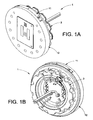
- the joint assembly 1 When fully assembled, in the embodiment shown in Figs. 1A and 1B , the joint assembly 1 forms a compact assembly that provides robust mechanical attachment, multiple weather-sealed electrical connections, and integral torque sensing.
- the mechanical attachment between the female side connector 12 and male side connector 3 is achieved when blade 10 or other load bearing projection of the male side connector assembly slides into a socket 29 or other receiver in the female connector 12 .
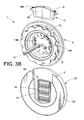
- Fig. 3B shows that a U-shaped socket 29 is defined in the female side assembly 12 for this purpose.
- blade 10 is received into or under the lip 17 in the socket 29.
- Electrical contact or communication through the joint can be achieved via one or more flat contacts 2, 2A, 2B, 2C, 4, and 9 in the male connector 3 which engage suitable elements in the female connector 12.
- electrical communication is established when the plurality of spring pins 18 (see Fig. 4B ) in the female side connector 12 are seated against the contacts in the male connector as would typically occur upon full insertion of the blade 10 into the socket 29.
- a pocket 5 ( Fig. 3B ) is formed above the socket 29 for receiving the locking clip assembly 11 once the male and female connectors are fully joined or engaged.
- a unique feature of the instant disclosure is the ability of the modular limb joint assembly to sense torque, load, and/or pressure, etc. about the cylindrical axis of the connector assembly (or the axis of rotation of the joint). This can be measured by means of strain gages 13A and 13B and a strain gage signal conditioning circuit board 8 ( Figs. 3B , 5A and 5B ) mounted to the back of the male blade 10 .
- One or more electrical connectors 43 can be used for maintaining electrical communication to the conditioning circuit board 8 , strain gages 13A , 13B , and/or other electronics through the various components of the limb, joint assembly, or individual male/female connectors. It should be noted that the strain gages 13A, 13B could include a full, half, or quarter strain gage bridge.
- strain gages While the use of strain gages is illustrated in the instant disclosure, other torque or load sensing devices can be used such as load cells, piezoelectric sensors, or pressure/strain sensing semiconductors, etc.
- position sensors could be used to measure the relative rotational displacement between the male/female connectors of the joint which can then be used to calculate the associated torque and/or load values.
- Such torque or load sensing capability is advantageous for a number of reasons. For one, it allows for a modular limb controller to properly limit the stresses that the joint and limb are subject to thereby preventing damage to the joint and/or limb.
- load and/or torque information can be used by the controller to more accurately control limb motion, position, and/or to provide bio-feedback control, sensation, etc. for prosthetic limb users.
- An additional advantage is that torque or load sensing allows precise control of forces being exerted by the prosthetic limb on external objects (or people), thus preventing damage or injury to those objects or people.
- precise force control further enhances the stability of the system and/or limb as well as the stability of the objects being manipulated.
- torque and/or load sensing is also advantageous for controlling the impedance of each joint for the same reasons that force or torque control is.
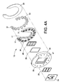
- the female side connector/assembly 12 may include a spring pin mounting circuit board 24 having electrical contacts 6 , 6A , 6B , 6C , 6D, and 6E ( Fig. 3A ), electrical spring pins 18 in spring pin blocks 25 (which are in electrical communication with contacts 6 - 6E ), a socket or receiver plate 34 , a connection backing 35 , an o-ring 26 , an electrical contact insulating member 28 , and a connection plain bearing 20.
- the spring pin circuit board 24 supports the spring pin blocks 25 which are both seated or received in a recess 27 of the connection backing 35.
- the insulating member 28 and the o-ring 26 are generally secured to either the spring pin circuit board 24 , the spring blocks 25 , and/or the connection backing 35 .
- a plurality of screws 32 , 33 can then be used to fasten together the socket or receiver plate 34 and the connection backing 35 (via holes 30 , 22) to a respective modular limb segment.
- the socket or female receiver 29 is formed between the lip 17 of the socket plate 34 and the connection backing 35 .
- Power and ground contacts 4 and 9 of the male joint connector 12 can each be contacted by multiple spring pins 18 to allow high electrical currents to flow across the joint.
- the male side connector/assembly 3 shown in exploded views in Figs. 5A and 5B , can include a torsion member 37 , a backing sheet 38 , a shim 40 , a connector side plain bearing 41 , a drive support 39 , a male joint connector subassembly 42 , strain gages 13A and 13B for measurement of torque in the connector/joint, a connection printed circuit board 8 , and internal wiring 15 .
- a plurality of countersunk clearance holes 21 may be used to allow the male side assembly to be bolted to an artificial arm assembly or respective segment of the modular limb (see Figs. 17 - 20 ).
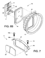
- Figs 6A and 6B show exploded views of the male joint connector subassembly 42 .
- the conductive power and ground contacts 4 and 9 the conductive communications bus contacts 2 , 2A , 2B, and 2C , an electrically insulating connection plug 44 , and the blade 10 (which may be made from hardened steel) are shown.
- knurling 45 can be formed on the housing 49 of the male joint connector subassembly 42 which increases the contact area with the toothed outer periphery of the polymer material of the torsion member 37 . This helps improve the mechanical bond and prevent or retard the torsion member from slipping.
- the torsion member can be a torsional spring manufactured from any material (plastic, rubber, metal, etc.) having the appropriate spring characteristics for the particular parameters (maximum load, stiffness, etc.) which the joint is designed to accommodate.
- the locking clip assembly 11 shown in an exploded view in Fig. 7 , includes a plain bearing 23 , a lock or clip 46 , and socket cap screws 19 and 19A.
- the plain bearing 23 (which can be made from a polymer based material) in this embodiment fits into recess 47 in lock 46 and the screws 19 and 19A fit into the counterbored clearance holes 48 and 48A .
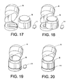
- the male side connector/assembly 3 and female side connector/assembly 12 can be attached to separate artificial arm sections (e.g., see modules A and B as shown in Figs. 17 - 20 ). These can be a humeral rotator and an elbow, as illustrated in Figs. 17-20 . However, they can, instead, be other limb segments of an arm or a leg or a robot.
- the joint connection process begins by first sliding blade 10 of male side connector 3 into the socket/receiver 29 of female side connector 12 . The joint connection is fully established when blade 10 is fully engaged in a sliding interference fit with edge or lip 17 in receiver/socket 29 . These steps are shown in Figs.
- the locking clip assembly 11 is inserted into receiver 29 after blade 10 is fully engaged with edge/lip 17 .
- the screws 19 and 19A are driven into threaded holes 31 (see Figs. 4A-4B ) and tightened.
- the modular limb joint assembly 1 is thus configured as shown in Figs. 1A and 1B .
- Fig. 20 shows the two arm section modules in a connected fashion.
- the first arm section can be the humeral rotator A and the second arm section can be an elbow B .
- the two limb sections which are joined can be, for example, a wrist connection to a forearm or an upper arm connection to a shoulder.
- blade 10 transfers rotational and linear mechanical loads from the male connector 3 to the socket/receiver 29 in the female connector 12.
- Electrical contacts 4 , 9 , 2 , 2A , 2B, and 2C transfer power and electrical signals from the male connector 3 to spring pins 18 in the female connector 12.
- Torsion member 37 and plain bearing 41 allow rotation of the male joint connector subassembly portion 42 in relation to the base/drive support 39 .
- the rotation allowed by torsion member 37 reduces the torsional stiffness of the connector about the axis of torsion member 37 so that torsional shock loads transferred across the joint are minimized.
- the reduced stiffness allowed by torsion member 37 also allows better control of torque passing through the joint.
- joint torque is measured by means of strain gages 13A and 13B mounted in male joint inner connector portion 42 . It should be noted that the strain gages or other load, torque, or position sensing devices can be located in either or both of the male and female side connectors.
- FIG. 8 Another embodiment of the joint assembly 100 is shown in Figs. 8 through 16 .
- the joint assembly 100 has a male side connector 50 which slides into a female side connector 65 .
- a sliding motion along the aligned axes of the male side connector 50 and the female side connector 65 is contemplated.
- a locking lever assembly 56 secures together the two associated limb segments attached to the respective male/female side connectors of the joint assembly.
- the joint assembly 100 When fully assembled as shown in Fig. 8 the joint assembly 100 forms a compact joint that provides robust mechanical attachment, multiple weather-sealed electrical connections, and integral torque sensing.
- the mechanical attachment between female side connector 65 and male side connector 50 is achieved when a plurality of tabs 52 on a hub portion 74b of the male side connector slide into a plurality of slots or notches 62 in the socket/receiver of the female connector.
- an indexing tab 51 slides into an indexing slot 63 in the female receiver 64 in order to correctly orient the male side assembly in relation to the female side assembly.
- the tabs, slots, or notches can be arranged in any configuration and on either connector so as to facilitate positive traction or engagement between the male and female connectors of the joint for the purpose of transmitting torsional as well as axial loads.
- Electrical contact/communication can be achieved through flat contacts 69 , 70 , 71, and 72 in male side connector 50 when such contacts engage a plurality of spring pins 68 in the female side connector 65 .
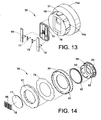
- the male side connector 50 is shown in an exploded view in Fig. 13 .
- the male connector 50 may include a cup or base portion 74a , the load bearing hub or projection 74b , a connection plug 75 , a plug recess 76 , and electrical contacts 69 , 70 , 71 , and 72 .
- torque about the cylindrical axis (or axis of rotation) of the joint assembly can be measured by means of strain gauges 49A and 49B mounted to the male connector 50 (as illustrated) or to the female connector 65.
- the female side connector 65 may include a spring pin mounting circuit board 77 , electrical spring pins 68 in spring pin blocks 78 , a torsional member 67 , a backing sheet 79 , a housing 80 , a plain bearing 82 , and a female receiver or socket 64 .
- Power and ground contacts 69 and 70 can each be contacted by multiple spring pins 68 to allow high electrical currents to flow across the joint assembly.
- knurling 83 can also be formed on the body of the socket 49 of the female joint connector 65 which increases the contact area with the toothed inner periphery of the torsion member 67 .
- the housing 80 can be knurled or toothed so as to mesh with a toothed outer periphery of the torsion member 67 . This helps improve the mechanical bond and prevent or retard slipping between the torsion member and the male and/or female joint connectors.
- the locking lever assembly 56 shown in an exploded view in Fig. 16 , can be composed of a locking collar 54 , a locking lever 57 , a pin 86 , a pull rod 88 , and a nut 91 .
- a head portion 87 of the pull rod 88 is pivotally secured in a lobed end 85 of the lever 57 by the pin 86 .
- Rotating the lever 57 causes a split 89 in the collar 54 to open or close, depending on the direction of rotation. In this manner, when the lever assembly 56 is placed in a locked state, it cinches the socket/receiver of the female connector about the hub portion of the male connector creating a rigid joint connection.
- a locking lever guard 59 ( Figs. 11-12 ) may also be provided and secured to the housing 80 by way of fasteners 58A-58C . It should be appreciated that other locking lever assembly constructions can also be employed.
- the male side connector 50 and female side connector 65 are attached to separate limb segments or modules (not shown for this embodiment) that are to be joined together using the previously described joint assembly. In one embodiment, these can be a wrist and a forearm, for example.
- the joint is established by first sliding the tabs 52 of male connector 50 into slots 62 of the socket/receiver 64 of female connector 65 (with the male and female sides oriented so that indexing tab 51 engages indexing slot 63 ).
- the male and female connectors are fully engaged when tabs 52 and 51 bottom in slots 62 and 63 of the receiver 64 .
- power and ground contacts 69 and 70 are in intimate contact with a plurality of conductive spring pins 68
- communications contacts 71 and 72 are each in intimate contact with a single spring pin 68 .
- locking lever 57 (shown opened in Fig. 9 ) is pushed down into the position shown in Fig. 8 to clamp female socket/receiver 64 around hub portion 74b ( Fig. 13 ). The joint is thus established as shown in Fig. 8 .
- tabs 52 and 51 transfer torque to slots/notches 62 and 63 in socket/receiver 64 in the female side assembly 65.
- Electrical contacts 69 , 70 , 71 , and 72 transfer electrical power and electrical signals from the male connector 50 to spring pins 68 in the female connector 65 thus establishing electrical communication between the limb segments of the artificial limb.
- Torsion member 67 and plain bearing 82 allow rotation of female receiver/socket 64 with respect to housing/base 80 about the cylindrical axis of housing 80 .
- the rotation allowed by torsion member 67 reduces the torsional stiffness of the connector about the axis of spring 67 so that torsional shock loads transferred across the joint are minimized.
- the reduced stiffness allowed by torsion member 67 also facilitates better control of torque passing through the joint.
- Torque in the joint can be measured by means of strain gages 49A and 49B mounted to the male connector 50 . As discussed with respect to the first embodiment, other known means for measuring torque are also contemplated.
- the modular limb joint assembly disclosed herein can be used to connect multiple modules or segments of an associated modular limb in series. It provides a high strength mechanical connection capable of bearing high torque and axial loads, as well as an integral electrical connection for power and signals. It also includes integral torque sensing elements. Further, it provides an elastic element, compliance element, or torsion member which enables some resiliency in the joint. It should be noted that the torsion member may also serve as a series elastic element within the joint assembly which is effectively in series between the "input" or driving end of the joint and the "output" or driven end of the joint. Such a series elastic element may act as low pass filter effectively filtering out shock loads while providing enhanced force control and stability (particularly when coupled with load or torque sensors as described previously). A more detailed discussion of the advantages of using a series elastic element can be found in U.S. Patent No. 5,910,720 to Williamson, et al.
- Typical artificial limbs such as prosthetic arms or robot arms, are designed as a single integrated assembly which cannot be simply and quickly disassembled into component modules. Moreover, such arms are not designed with load and/or torque sensing elements which are integral to the connector, since they do not even have a modular connector. Due to the lack of easily connectible limb modules or segments, typical man-made arms do not have a single assembly which combines the mechanical and electrical interface with a load and/or torque sensor, as well as a compliance element, as in the disclosed embodiments.
- a new and improved artificial limb such as an arm, which comprises modular segments.
- an integral torque sensor can be provided along with a compliance or torsion element to allow the joint between two segments of a limb to function better.
- a connecting device which electrically connects first and second components of an artificial limb.
- the connecting device comprises a first component block including a blade and a second component block including a socket in which the blade is selectively accommodated.
- a locking clip can selectively secure the first component block to the second component block.
- a joint for an artificial limb.
- the joint comprises a first connector including a blade and a first electrical contact surface and a second connector including a socket in which the blade is selectively accommodated, the socket including a second electrical contact surface.
- a locking clip is provided for securing the first connector to the second connector. Electrical communication is achieved between the first and second connectors when the first and second electrical contact surfaces are in contact with each other.
Landscapes
- Health & Medical Sciences (AREA)
- Engineering & Computer Science (AREA)
- Transplantation (AREA)
- Heart & Thoracic Surgery (AREA)
- Life Sciences & Earth Sciences (AREA)
- Oral & Maxillofacial Surgery (AREA)
- Mechanical Engineering (AREA)
- Biomedical Technology (AREA)
- Robotics (AREA)
- Vascular Medicine (AREA)
- Cardiology (AREA)
- Animal Behavior & Ethology (AREA)
- General Health & Medical Sciences (AREA)
- Public Health (AREA)
- Veterinary Medicine (AREA)
- Orthopedic Medicine & Surgery (AREA)
- Prostheses (AREA)
Description
- The present invention relates to man-made or artificial limbs for prosthetic or orthotic devices, as well as for robots. More particularly, it relates to a modular limb segment connector, such as an arm segment connector, which can be used in prosthetics, as well as for robotics applications when an artificial limb is required.
- In the field of prosthetics, there remains a limited ability to control prosthetic and/or orthotic joints in a suitable manner for practical clinical application. While great strides have been made in prosthetic legs, the development of prosthetic arms has not been as advanced. Typically, limbs such as arms, whether for prosthetics or robotics, are assembled with custom bolted and screwed mechanical connections that are different for each joint. These mechanical connections may or may not include the electrical interconnections between adjacent arm components. Typical solutions can include complex wiring harnesses that require bulky electrical connectors or solder connections. Such solutions are disadvantageous because they only work for a specific joint. In other words, they are not usable for joints between multiple arm modules.
- Although prosthetic technology has advanced in recent years, the prior art still has failed to bridge the gap between manmade prosthetics and user demands and needs. Therefore, an extensive opportunity for design advancements and innovation remains where the prior art fails or is deficient. Most myoelectric prosthetic arms move in three ways. They bend at the elbow, rotate at the wrist and a rudimentary hand clamps shut. A need exists to replicate the great many varieties of movements that a human arm is capable of making. It is believed that a human arm has 27 degrees of freedom, including individual finger bending, and the use of an opposable thumb. Robotic arms used as prostheses are not fully articulated to give the user the same degrees of freedom as a natural arm, not to mention the speed and torque of a human arm. Moreover, the human arm can sense pressure, which conventional man-made arms cannot do. It would be advantageous if the prosthetic or robotic arm was sensitive enough to pick up a piece of paper, a wine glass or even a grape without mishap.
- While many advances are taking place to allow for better prosthetics and orthotics, as well as more functional robotic limbs, there remains a need to develop better connections for the various segments of a limb so that the segments can be more readily attached and detached in a simple manner, without external wiring, and in a manner that provides a weather tight seal. It would also be advantageous to provide sensors for torque being transmitted between adjacent components of a limb.
-
US 4,512,709 discloses a robot toolchanger system where an adapter unit is mounted to the end effector of a robot. The preamble of appendedclaim 1 is based on this disclosure. -
DE 103 26 239 discloses a quick-change system, in particular a gripper change system, for detecting and transporting workpieces. -
US 5,800,563 discloses an impact reducing prosthetic pylon having a distal component which can be attached to a prosthetic foot. -
US 2005/0267600 discloses an alignment assembly for a modular prosthesis which can be selectively connected to each other for providing linear adjustability. -
US 2008/0276725 discloses a sensor assembly for measuring forces and/or torques which are transmitted by means of a rigid transmitter having a first part and a second part. - According to the present invention, a joint assembly for releasably securing a first and a second segment of an associated modular limb as defined in
claim 1 is provided. The joint assembly comprising a male connector including a base and a load bearing projection secured to the base of the male connector protruding therefrom. The male connector is adapted to be secured to one of the first and second segments of the associated modular limb. A female connector is provided and includes a base and a load bearing socket secured to the base of the female connector. The socket is configured to selectively receive the projection of the male connector. The female connector is adapted to be secured to the other of the first and second segments of the associated modular limb. A locking member selectively retains the projection of the male connector in the socket of the female connector. One of the male or the female connector includes a torsion member made of a resilient material for reducing a torsional stiffness of the joint assembly. The torsion member comprises one of: a toothed outer periphery for engaging knurling formed on housing of a male connector assembly of the male connector when the connector includes the torsion member; or a toothed inner periphery for engaging knurling formed on the body of a socket of the female connector when the female connector includes the torsion member. The male connector, the female connector, and the locking member cooperate to form a resilient and selectively releasable modular limb joint. -
-
Figs. 1A and 1B show a fully assembled and mated connector according to a first embodiment of the present invention. -
Fig. 2 shows a partially disassembled connector ofFig. 1A with a locking clip removed and male and female connector sides partially removed from each other. -
Figs. 3A and3B show the connector ofFig. 2 in a fully disassembled condition. -
Figs. 4A and4B show exploded views of the female side of the connector ofFig. 2 . -
Figs. 5A and5B show exploded views of the male side of the connector ofFig. 2 . -
Figs. 6A and6B show exploded views of the blade and electrical contact assembly of the male side of the connector ofFig. 2 . -
Fig. 7 shows an exploded view of the locking clip assembly of the connector ofFig. 2 . -
Fig. 8 shows a fully engaged and clamped connector according to a second embodiment of the present invention. -
Fig. 9 shows the connector ofFig. 8 with a locking lever open. -
Fig. 10 shows the connector ofFig. 8 with the locking lever open and male and female sides disengaged. -
Figs. 11 and 12 show exploded views of a connector assembly ofFig. 8 . -
Fig. 13 shows an exploded view of the male side of the connector ofFig. 8 . -
Figs. 14 and15 show exploded views of the female side of the connector ofFig. 8 . -
Fig. 16 shows an exploded view of a locking lever assembly of the connector ofFig. 8 . -
Figs. 17 - 20 show the steps involved in securing a first limb element to a second limb element when employing the male side assembly and female side assembly illustrated inFigs. 1A - 7 . - One embodiment of the connector or
modular joint assembly 1 for an artificial limb is shown inFigs. 1A through 7 . As is shown in the drawings and particularly inFig. 2 , the joint assembly includes amale side connector 3 which slides into afemale side connector 12. A locking member orclip assembly 11 secures the two sides of the connector. The male connector, female connector, and locking member cooperate to form the resilient yet selectively releasablemodular limb joint 1. - When fully assembled, in the embodiment shown in
Figs. 1A and 1B , thejoint assembly 1 forms a compact assembly that provides robust mechanical attachment, multiple weather-sealed electrical connections, and integral torque sensing. As is shown in particular inFigs. 3A and3B , the mechanical attachment between thefemale side connector 12 andmale side connector 3 is achieved whenblade 10 or other load bearing projection of the male side connector assembly slides into asocket 29 or other receiver in thefemale connector 12. In particular,Fig. 3B shows that aU-shaped socket 29 is defined in thefemale side assembly 12 for this purpose. In the instant embodiment,blade 10 is received into or under thelip 17 in thesocket 29. Electrical contact or communication through the joint can be achieved via one or moreflat contacts male connector 3 which engage suitable elements in thefemale connector 12. By way of example only, electrical communication is established when the plurality of spring pins 18 (seeFig. 4B ) in thefemale side connector 12 are seated against the contacts in the male connector as would typically occur upon full insertion of theblade 10 into thesocket 29. Also, a pocket 5 (Fig. 3B ) is formed above thesocket 29 for receiving the lockingclip assembly 11 once the male and female connectors are fully joined or engaged. - A unique feature of the instant disclosure is the ability of the modular limb joint assembly to sense torque, load, and/or pressure, etc. about the cylindrical axis of the connector assembly (or the axis of rotation of the joint). This can be measured by means of
strain gages Figs. 3B ,5A and5B ) mounted to the back of themale blade 10. One or moreelectrical connectors 43 can be used for maintaining electrical communication to theconditioning circuit board 8,strain gages strain gages - While the use of strain gages is illustrated in the instant disclosure, other torque or load sensing devices can be used such as load cells, piezoelectric sensors, or pressure/strain sensing semiconductors, etc. In addition, position sensors could be used to measure the relative rotational displacement between the male/female connectors of the joint which can then be used to calculate the associated torque and/or load values.
- Such torque or load sensing capability is advantageous for a number of reasons. For one, it allows for a modular limb controller to properly limit the stresses that the joint and limb are subject to thereby preventing damage to the joint and/or limb. In addition, such load and/or torque information can be used by the controller to more accurately control limb motion, position, and/or to provide bio-feedback control, sensation, etc. for prosthetic limb users. An additional advantage is that torque or load sensing allows precise control of forces being exerted by the prosthetic limb on external objects (or people), thus preventing damage or injury to those objects or people. Furthermore, precise force control further enhances the stability of the system and/or limb as well as the stability of the objects being manipulated. Moreover, torque and/or load sensing is also advantageous for controlling the impedance of each joint for the same reasons that force or torque control is.
- As is shown in the exploded views in
Figs. 4A and4B , the female side connector/assembly 12 may include a spring pin mountingcircuit board 24 havingelectrical contacts Fig. 3A ), electrical spring pins 18 in spring pin blocks 25 (which are in electrical communication with contacts 6 - 6E), a socket orreceiver plate 34, aconnection backing 35, an o-ring 26, an electricalcontact insulating member 28, and a connectionplain bearing 20. As illustrated inFigs. 4A and4B , the springpin circuit board 24 supports the spring pin blocks 25 which are both seated or received in arecess 27 of theconnection backing 35. The insulatingmember 28 and the o-ring 26 are generally secured to either the springpin circuit board 24, the spring blocks 25, and/or theconnection backing 35. A plurality ofscrews receiver plate 34 and the connection backing 35 (viaholes 30, 22) to a respective modular limb segment. Once assembled, the socket orfemale receiver 29 is formed between thelip 17 of thesocket plate 34 and theconnection backing 35. Power andground contacts joint connector 12 can each be contacted by multiple spring pins 18 to allow high electrical currents to flow across the joint. - The male side connector/
assembly 3, shown in exploded views inFigs. 5A and5B , can include atorsion member 37, abacking sheet 38, ashim 40, a connector sideplain bearing 41, adrive support 39, a malejoint connector subassembly 42,strain gages circuit board 8, andinternal wiring 15. A plurality of countersunkclearance holes 21 may be used to allow the male side assembly to be bolted to an artificial arm assembly or respective segment of the modular limb (seeFigs. 17 - 20 ). -
Figs 6A and6B show exploded views of the malejoint connector subassembly 42. In particular, the conductive power andground contacts communications bus contacts connection plug 44, and the blade 10 (which may be made from hardened steel) are shown. In addition, knurling 45 can be formed on thehousing 49 of the malejoint connector subassembly 42 which increases the contact area with the toothed outer periphery of the polymer material of thetorsion member 37. This helps improve the mechanical bond and prevent or retard the torsion member from slipping. It should be noted the torsion member can be a torsional spring manufactured from any material (plastic, rubber, metal, etc.) having the appropriate spring characteristics for the particular parameters (maximum load, stiffness, etc.) which the joint is designed to accommodate. - The locking
clip assembly 11, shown in an exploded view inFig. 7 , includes aplain bearing 23, a lock orclip 46, andsocket cap screws recess 47 inlock 46 and thescrews clearance holes - In operation, the male side connector/
assembly 3 and female side connector/assembly 12 can be attached to separate artificial arm sections (e.g., see modules A and B as shown inFigs. 17 - 20 ). These can be a humeral rotator and an elbow, as illustrated inFigs. 17-20 . However, they can, instead, be other limb segments of an arm or a leg or a robot. As is shown inFig. 2 , the joint connection process begins by first slidingblade 10 ofmale side connector 3 into the socket/receiver 29 offemale side connector 12. The joint connection is fully established whenblade 10 is fully engaged in a sliding interference fit with edge orlip 17 in receiver/socket 29. These steps are shown inFigs. 17 and 19 . When full engagement is achieved then power andground contacts communications contacts respective spring pin 18. - To ensure that the
male side connector 3 andfemale side connector 12 do not become disengaged during service or operation, the lockingclip assembly 11 is inserted intoreceiver 29 afterblade 10 is fully engaged with edge/lip 17. In the embodiment shown, thescrews Fig. 7 ) are driven into threaded holes 31 (seeFigs. 4A-4B ) and tightened. Of course, other ways of securing the locking clip in place, in a manner that the clip can be detached as needed when disassembling the joint, are also contemplated. The modular limbjoint assembly 1 is thus configured as shown inFigs. 1A and 1B . Similarly,Fig. 20 shows the two arm section modules in a connected fashion. In the embodiment shown, the first arm section can be the humeral rotator A and the second arm section can be an elbow B. However, other embodiments are also contemplated. In other words, the two limb sections which are joined can be, for example, a wrist connection to a forearm or an upper arm connection to a shoulder. - When the male and female connectors are fully engaged,
blade 10 transfers rotational and linear mechanical loads from themale connector 3 to the socket/receiver 29 in thefemale connector 12.Electrical contacts male connector 3 to spring pins 18 in thefemale connector 12. -
Torsion member 37 andplain bearing 41 allow rotation of the male jointconnector subassembly portion 42 in relation to the base/drive support 39. The rotation allowed bytorsion member 37 reduces the torsional stiffness of the connector about the axis oftorsion member 37 so that torsional shock loads transferred across the joint are minimized. The reduced stiffness allowed bytorsion member 37 also allows better control of torque passing through the joint. In the embodiment illustrated, joint torque is measured by means ofstrain gages inner connector portion 42. It should be noted that the strain gages or other load, torque, or position sensing devices can be located in either or both of the male and female side connectors. - Another embodiment of the
joint assembly 100 is shown inFigs. 8 through 16 . As is shown in the drawings and particularly inFig. 10 , thejoint assembly 100 has amale side connector 50 which slides into afemale side connector 65. In this embodiment, a sliding motion along the aligned axes of themale side connector 50 and thefemale side connector 65 is contemplated. A lockinglever assembly 56 secures together the two associated limb segments attached to the respective male/female side connectors of the joint assembly. - When fully assembled as shown in
Fig. 8 thejoint assembly 100 forms a compact joint that provides robust mechanical attachment, multiple weather-sealed electrical connections, and integral torque sensing. As is shown in particular inFigs. 9 - 12 , the mechanical attachment betweenfemale side connector 65 andmale side connector 50 is achieved when a plurality oftabs 52 on ahub portion 74b of the male side connector slide into a plurality of slots ornotches 62 in the socket/receiver of the female connector. Moreover, anindexing tab 51 slides into anindexing slot 63 in thefemale receiver 64 in order to correctly orient the male side assembly in relation to the female side assembly. Naturally, the tabs, slots, or notches can be arranged in any configuration and on either connector so as to facilitate positive traction or engagement between the male and female connectors of the joint for the purpose of transmitting torsional as well as axial loads. Electrical contact/communication can be achieved throughflat contacts male side connector 50 when such contacts engage a plurality of spring pins 68 in thefemale side connector 65. - The
male side connector 50 is shown in an exploded view inFig. 13 . In general, themale connector 50 may include a cup orbase portion 74a, the load bearing hub orprojection 74b, aconnection plug 75, aplug recess 76, andelectrical contacts strain gauges female connector 65. - As is shown in the exploded views in
Figs. 14 and15 , thefemale side connector 65 may include a spring pin mountingcircuit board 77, electrical spring pins 68 in spring pin blocks 78, atorsional member 67, abacking sheet 79, ahousing 80, aplain bearing 82, and a female receiver orsocket 64. Power andground contacts 69 and 70 (Fig. 13 ) can each be contacted by multiple spring pins 68 to allow high electrical currents to flow across the joint assembly. In addition, knurling 83 can also be formed on the body of thesocket 49 of the femalejoint connector 65 which increases the contact area with the toothed inner periphery of thetorsion member 67. Similarly, as best illustrated inFig. 14 , thehousing 80 can be knurled or toothed so as to mesh with a toothed outer periphery of thetorsion member 67. This helps improve the mechanical bond and prevent or retard slipping between the torsion member and the male and/or female joint connectors. - The locking
lever assembly 56, shown in an exploded view inFig. 16 , can be composed of alocking collar 54, a lockinglever 57, apin 86, apull rod 88, and anut 91. Ahead portion 87 of thepull rod 88 is pivotally secured in alobed end 85 of thelever 57 by thepin 86. Rotating thelever 57 causes asplit 89 in thecollar 54 to open or close, depending on the direction of rotation. In this manner, when thelever assembly 56 is placed in a locked state, it cinches the socket/receiver of the female connector about the hub portion of the male connector creating a rigid joint connection. In addition, a locking lever guard 59 (Figs. 11-12 ) may also be provided and secured to thehousing 80 by way offasteners 58A-58C. It should be appreciated that other locking lever assembly constructions can also be employed. - In operation, the
male side connector 50 andfemale side connector 65 are attached to separate limb segments or modules (not shown for this embodiment) that are to be joined together using the previously described joint assembly. In one embodiment, these can be a wrist and a forearm, for example. As is shown inFig. 10 , the joint is established by first sliding thetabs 52 ofmale connector 50 intoslots 62 of the socket/receiver 64 of female connector 65 (with the male and female sides oriented so thatindexing tab 51 engages indexing slot 63). The male and female connectors are fully engaged whentabs slots receiver 64. When full engagement is achieved, power andground contacts communications contacts single spring pin 68. - To ensure that the
male connector 50 andfemale connector 65 do not become disengaged during operation of the artificial, prosthetic, or robotic limb, locking lever 57 (shown opened inFig. 9 ) is pushed down into the position shown inFig. 8 to clamp female socket/receiver 64 aroundhub portion 74b (Fig. 13 ). The joint is thus established as shown inFig. 8 . - When the joint is fully established,
tabs notches receiver 64 in thefemale side assembly 65.Electrical contacts male connector 50 to spring pins 68 in thefemale connector 65 thus establishing electrical communication between the limb segments of the artificial limb. -
Torsion member 67 andplain bearing 82 allow rotation of female receiver/socket 64 with respect to housing/base 80 about the cylindrical axis ofhousing 80. The rotation allowed bytorsion member 67 reduces the torsional stiffness of the connector about the axis ofspring 67 so that torsional shock loads transferred across the joint are minimized. The reduced stiffness allowed bytorsion member 67 also facilitates better control of torque passing through the joint. Torque in the joint can be measured by means ofstrain gages male connector 50. As discussed with respect to the first embodiment, other known means for measuring torque are also contemplated. - The modular limb joint assembly disclosed herein can be used to connect multiple modules or segments of an associated modular limb in series. It provides a high strength mechanical connection capable of bearing high torque and axial loads, as well as an integral electrical connection for power and signals. It also includes integral torque sensing elements. Further, it provides an elastic element, compliance element, or torsion member which enables some resiliency in the joint. It should be noted that the torsion member may also serve as a series elastic element within the joint assembly which is effectively in series between the "input" or driving end of the joint and the "output" or driven end of the joint. Such a series elastic element may act as low pass filter effectively filtering out shock loads while providing enhanced force control and stability (particularly when coupled with load or torque sensors as described previously). A more detailed discussion of the advantages of using a series elastic element can be found in
U.S. Patent No. 5,910,720 to Williamson, et al. - Typical artificial limbs, such as prosthetic arms or robot arms, are designed as a single integrated assembly which cannot be simply and quickly disassembled into component modules. Moreover, such arms are not designed with load and/or torque sensing elements which are integral to the connector, since they do not even have a modular connector. Due to the lack of easily connectible limb modules or segments, typical man-made arms do not have a single assembly which combines the mechanical and electrical interface with a load and/or torque sensor, as well as a compliance element, as in the disclosed embodiments.
- Disclosed has been a new and improved artificial limb, such as an arm, which comprises modular segments. With the system disclosed herein, the reliability and safety of the electrical connection can be improved. At the same time, an integral torque sensor can be provided along with a compliance or torsion element to allow the joint between two segments of a limb to function better.
- According to one embodiment of the present disclosure, there is provided a connecting device which electrically connects first and second components of an artificial limb. The connecting device comprises a first component block including a blade and a second component block including a socket in which the blade is selectively accommodated. A locking clip can selectively secure the first component block to the second component block.
- According to another embodiment of the present disclosure, a joint is provided for an artificial limb. The joint comprises a first connector including a blade and a first electrical contact surface and a second connector including a socket in which the blade is selectively accommodated, the socket including a second electrical contact surface. A locking clip is provided for securing the first connector to the second connector. Electrical communication is achieved between the first and second connectors when the first and second electrical contact surfaces are in contact with each other.
- The disclosure has been described with reference to several embodiments. Obviously, alterations and modifications will occur to others upon a reading and understanding of this specification. It is intended to include all such modifications and alterations insofar as they come within the scope of the appended claims or the equivalents thereof.
Claims (8)
- A joint assembly (1) for releasably securing a first (A) and a second (B) segment of an associated modular limb, the joint assembly comprising:a male connector (3) including a base (42) and a load bearing projection (10) secured to the base of the male connector and protruding therefrom, the male connector being adapted to be secured to one of the first and second segments of the associated modular limb;a female connector (12) including a base and a load bearing socket (29) secured to the base of the female connector, the socket being configured to selectively receive the projection of the male connector, the female connector being adapted to be secured to the other of the first and second segments of the associated modular limb;a locking member (11) selectively retaining the projection of the male connector in the socket of the female connector;characterised in thatone of the male or the female connector includes a torsion member (37, 67) made of a resilient material for reducing a torsional stiffness of the joint assembly;the torsion member comprising one of:a toothed outer periphery for engaging knurling (45) formed on housing of a male connector subassembly of the male connector when the male connector includes the torsion member; ora toothed inner periphery for engaging knurling formed on the body of a socket of the female connector when the female connector includes the torsion member; andwherein the male connector, the female connector, and the locking member cooperate to form a resilient and selectively releasable modular limb joint.
- The joint assembly of claim 1 wherein the male connector further includes a first electrical contact (2, 2A, 2B, 2C, 4, 9) mounted to the projection of the male connector and wherein the female connector further includes a second electrical contact (18) mounted to the socket of the female connector, the first electrical contact being aligned with the second electrical contact when the projection is received in the socket for establishing electrical communication between the first and second segments of the associated modular limb.
- The joint assembly of claim 1 or 2, wherein the torsion member is ring shaped and disposed between the projection (10) and the base of the male connector.
- The joint assembly of any preceding claim, wherein one of the male connector and the female connector includes a load sensor (13A, 13B) for measuring a torsional load across the joint.
- The joint assembly of claim 4, wherein the load sensor comprises one of a full, half, or quarter strain gage bridge.
- The joint assembly of claim 5, wherein the strain gage bridge includes a first half and a second half, the first half of the bridge being disposed adjacent the projection at a first location spaced from an axis of rotation of the joint and the second half of the bridge being disposed adjacent the projection at a second location spaced from the axis of rotation of the joint.
- The joint assembly of any preceding claim, further including a weathertight seal disposed between the male connector and the female connector.
- The joint assembly of any preceding claim, wherein the locking member comprises one of a clip (46) and a collar (54).
Applications Claiming Priority (3)
| Application Number | Priority Date | Filing Date | Title |
|---|---|---|---|
| US26762909P | 2009-12-08 | 2009-12-08 | |
| US12/959,816 US8425620B2 (en) | 2009-12-08 | 2010-12-03 | Modular limb segment connector |
| PCT/US2010/059229 WO2011071878A1 (en) | 2009-12-08 | 2010-12-07 | Modular limb segment connector |
Publications (2)
| Publication Number | Publication Date |
|---|---|
| EP2509541A1 EP2509541A1 (en) | 2012-10-17 |
| EP2509541B1 true EP2509541B1 (en) | 2015-03-25 |
Family
ID=44082470
Family Applications (1)
| Application Number | Title | Priority Date | Filing Date |
|---|---|---|---|
| EP10795836.5A Active EP2509541B1 (en) | 2009-12-08 | 2010-12-07 | Modular limb segment connector |
Country Status (3)
| Country | Link |
|---|---|
| US (2) | US8425620B2 (en) |
| EP (1) | EP2509541B1 (en) |
| WO (1) | WO2011071878A1 (en) |
Cited By (1)
| Publication number | Priority date | Publication date | Assignee | Title |
|---|---|---|---|---|
| WO2025237803A1 (en) * | 2024-05-13 | 2025-11-20 | Otto Bock Healthcare Products Gmbh | Multi-part prosthesis having a proximal component and a distal component, and such components |
Families Citing this family (49)
| Publication number | Priority date | Publication date | Assignee | Title |
|---|---|---|---|---|
| US10342461B2 (en) | 2007-10-15 | 2019-07-09 | Alterg, Inc. | Method of gait evaluation and training with differential pressure system |
| WO2014153201A1 (en) | 2013-03-14 | 2014-09-25 | Alterg, Inc. | Method of gait evaluation and training with differential pressure system |
| EP2542391B1 (en) * | 2010-03-02 | 2014-06-25 | ABB Research Ltd. | A system for electrically connecting a tool to a robot wrist and a method therefor |
| IT1404527B1 (en) * | 2011-02-24 | 2013-11-22 | Comau Spa | ARTICULATED ROBOT WRIST. |
| IT1404528B1 (en) * | 2011-02-24 | 2013-11-22 | Comau Spa | ARTICULATED ROBOT WRIST. |
| GB201114264D0 (en) | 2011-08-18 | 2011-10-05 | Touch Emas Ltd | Improvements in or relating to prosthetics and orthotics |
| GB201302025D0 (en) | 2013-02-05 | 2013-03-20 | Touch Emas Ltd | Improvements in or relating to prosthetics |
| US9914003B2 (en) | 2013-03-05 | 2018-03-13 | Alterg, Inc. | Monocolumn unweighting systems |
| WO2014153016A1 (en) | 2013-03-14 | 2014-09-25 | Alterg, Inc. | Cantilevered unweighting systems |
| US10265565B2 (en) | 2013-03-14 | 2019-04-23 | Alterg, Inc. | Support frame and related unweighting system |
| US20140308061A1 (en) * | 2013-04-16 | 2014-10-16 | Caterpillar Inc. | Method and System for Detecting Engagement with a Work Tool Accessory |
| US10046465B2 (en) * | 2013-06-06 | 2018-08-14 | Seiko Epson Corporation | Attaching and detaching device and robot |
| US9505136B1 (en) * | 2013-06-24 | 2016-11-29 | Redwood Robotics | Precision assembly of robotic components |
| TWI552743B (en) * | 2013-12-19 | 2016-10-11 | Hiwin Tech Corp | Inductive force feedback mechanism |
| GB201403265D0 (en) | 2014-02-25 | 2014-04-09 | Touch Emas Ltd | Prosthetic digit for use with touchscreen devices |
| JP2015169366A (en) * | 2014-03-06 | 2015-09-28 | 古河電気工業株式会社 | Solar heat collection device |
| GB201408253D0 (en) | 2014-05-09 | 2014-06-25 | Touch Emas Ltd | Systems and methods for controlling a prosthetic hand |
| ES2857728T3 (en) * | 2014-09-17 | 2021-09-29 | Soft Robotics Inc | Soft Robotic Actuator Fixing Hub and Electro-Adhesive Actuator and Gripper Assembly |
| GB201417541D0 (en) * | 2014-10-03 | 2014-11-19 | Touch Bionics Ltd | Wrist device for a prosthetic limb |
| US10189168B2 (en) | 2014-11-18 | 2019-01-29 | Soft Robotics, Inc. | Soft robotic actuator enhancements |
| US9592603B2 (en) * | 2014-12-01 | 2017-03-14 | Spin Master Ltd. | Reconfigurable robotic system |
| CN108883539B (en) * | 2016-03-29 | 2021-11-02 | 生活机器人学股份有限公司 | Mechanical arm mechanism and rotary joint device |
| US10369028B2 (en) * | 2016-04-22 | 2019-08-06 | Rehabilitation Institute Of Chicago | Safety overload for direct skeletal attachment |
| US11185426B2 (en) | 2016-09-02 | 2021-11-30 | Touch Bionics Limited | Systems and methods for prosthetic wrist rotation |
| DE102016125724B3 (en) | 2016-12-27 | 2018-05-03 | Otto Bock Healthcare Products Gmbh | Fastening arrangement of a prosthetic hand on a forearm shaft and prosthesis system |
| KR101980269B1 (en) | 2017-05-17 | 2019-05-21 | 한국과학기술연구원 | Module connection system |
| WO2018236225A1 (en) * | 2017-06-20 | 2018-12-27 | Opum Technologies Limited | Orthosis or exoskeleton system with modular elements |
| US11957954B2 (en) | 2017-10-18 | 2024-04-16 | Alterg, Inc. | Gait data collection and analytics system and methods for operating unweighting training systems |
| US10973660B2 (en) | 2017-12-15 | 2021-04-13 | Touch Bionics Limited | Powered prosthetic thumb |
| DE102017131193A1 (en) * | 2017-12-22 | 2019-06-27 | Otto Bock Healthcare Products Gmbh | Device for fixing two orthopedic components to each other |
| USD895706S1 (en) * | 2018-05-18 | 2020-09-08 | Universal Robots A/S | Robot joint having an input flange |
| USD898090S1 (en) * | 2018-05-18 | 2020-10-06 | Universal Robots A/S | Toothed connection flange for a robot joint |
| CN108839042A (en) * | 2018-07-23 | 2018-11-20 | 清华大学 | Control integrated module driving device |
| US11547581B2 (en) | 2018-12-20 | 2023-01-10 | Touch Bionics Limited | Energy conservation of a motor-driven digit |
| USD890829S1 (en) * | 2019-03-15 | 2020-07-21 | Misty Robotics, Inc. | Flange for a robotic arm |
| USD891494S1 (en) * | 2019-03-15 | 2020-07-28 | Misty Robotics, Inc. | Socket for a Robotic arm |
| CN113853181A (en) | 2019-04-10 | 2021-12-28 | 塔驰仿生有限公司 | Prosthetic fingers with articulated links |
| US11738893B2 (en) | 2019-04-30 | 2023-08-29 | Soft Robotics, Inc. | Picking, placing, and scanning bagged clothing and other articles |
| JP7319105B2 (en) * | 2019-06-27 | 2023-08-01 | ファナック株式会社 | Rotary axis structure and robot |
| CN110405809A (en) * | 2019-07-28 | 2019-11-05 | 南京昱晟机器人科技有限公司 | A kind of industrial robot having safety custody function and safety custody method |
| JP7396834B2 (en) * | 2019-08-23 | 2023-12-12 | ファナック株式会社 | Interface mechanism and horizontal articulated robot |
| US12527672B2 (en) | 2019-09-18 | 2026-01-20 | Touch Bionics Limited | Prosthetic digits and actuators |
| US11931270B2 (en) | 2019-11-15 | 2024-03-19 | Touch Bionics Limited | Prosthetic digit actuator |
| DE102020116481A1 (en) * | 2020-06-23 | 2021-12-23 | Otto Bock Healthcare Products Gmbh | Interface arrangement |
| US12115087B2 (en) | 2020-11-03 | 2024-10-15 | Touch Bionics Limited | Sensor for prosthetic control |
| KR102316139B1 (en) * | 2020-11-04 | 2021-10-22 | 만드로 주식회사 | Wrist joint structure of artificial hand |
| CN113977556B (en) * | 2021-11-15 | 2023-07-21 | 沈阳新松机器人自动化股份有限公司 | Compact type high-anti-overturning rotary mechanism |
| USD1099187S1 (en) | 2022-01-14 | 2025-10-21 | Universal Robots A/S | Robot joint |
| USD1082878S1 (en) | 2022-01-14 | 2025-07-08 | Universal Robots A/S | Robot joint |
Family Cites Families (35)
| Publication number | Priority date | Publication date | Assignee | Title |
|---|---|---|---|---|
| US910720A (en) | 1907-02-27 | 1909-01-26 | Rasmus Petersen | Drying apparatus. |
| JPS5890485A (en) | 1981-11-11 | 1983-05-30 | ロボティック・システムズ・リミテッド | Structure of robot |
| US4521924A (en) | 1983-03-01 | 1985-06-11 | University Of Utah | Electrically driven artificial arm |
| US4512709A (en) * | 1983-07-25 | 1985-04-23 | Cincinnati Milacron Inc. | Robot toolchanger system |
| US4766775A (en) * | 1986-05-02 | 1988-08-30 | Hodge Steven W | Modular robot manipulator |
| US4905938A (en) * | 1988-07-01 | 1990-03-06 | General Electric Company | Special purpose robotic end effector |
| GB2236054B (en) * | 1989-09-20 | 1993-10-06 | Steeper Hugh Ltd | Artificial wrist unit |
| EP0441397A1 (en) | 1990-02-09 | 1991-08-14 | Hitachi, Ltd. | Assembling a modular robot arm by means of a second robot arm |
| JPH07100786A (en) | 1993-10-01 | 1995-04-18 | Yaskawa Electric Corp | Unwired robot |
| US5523662A (en) * | 1994-05-02 | 1996-06-04 | Engineering Services, Inc. | Modular, expandable and reconfigurable robot |
| US5650704A (en) | 1995-06-29 | 1997-07-22 | Massachusetts Institute Of Technology | Elastic actuator for precise force control |
| US5800563A (en) * | 1995-12-22 | 1998-09-01 | Ohio Willow Wood Company | Impact reducing prosthetic pylon |
| US6686717B2 (en) * | 1997-04-01 | 2004-02-03 | Charles Khairallah | Modular articulated structure |
| GB9706625D0 (en) | 1997-04-01 | 1997-05-21 | Khairallah Charles | Hyper-redundant robot |
| KR20010053478A (en) | 1999-05-10 | 2001-06-25 | 이데이 노부유끼 | Connector and robot apparatus |
| US6780042B1 (en) * | 2000-08-03 | 2004-08-24 | Rutgers, The State University Of New Jersey | Active quick connecting/disconnecting connector |
| US6575802B2 (en) * | 2001-08-24 | 2003-06-10 | Xerox Corporation | Robotic toy modular system with distributed program |
| US6454624B1 (en) * | 2001-08-24 | 2002-09-24 | Xerox Corporation | Robotic toy with posable joints |
| US6605914B2 (en) * | 2001-08-24 | 2003-08-12 | Xerox Corporation | Robotic toy modular system |
| JP3756095B2 (en) * | 2001-10-01 | 2006-03-15 | 日本サーボ株式会社 | Articulated industrial robot and arm unit of the robot |
| DE10326239B4 (en) | 2003-06-11 | 2007-05-16 | Ass Maschb Gmbh | Quick-change system |
| US6972042B2 (en) * | 2003-08-28 | 2005-12-06 | Ampu-Clamp Llc | Quick-release tube clamp for modular lower limb prosthetic systems and method thereof |
| US8175747B2 (en) | 2003-12-22 | 2012-05-08 | Irobou Co., Ltd. | Joinable robot component for robot toy, modifiable robot toy using the joinable robot components, and control method thereof |
| US7338532B2 (en) * | 2004-05-27 | 2008-03-04 | Engineered Silicone Products L.L.C. | Alignment assembly for a prosthesis |
| US20070021841A1 (en) * | 2005-03-24 | 2007-01-25 | Bloorview Kids Rehab, A Corporation Registered Under The Ontario Corporations Act | Joint for prosthesis |
| US7296835B2 (en) | 2005-08-11 | 2007-11-20 | Anybots, Inc. | Robotic hand and arm apparatus |
| DE102005051495A1 (en) * | 2005-10-26 | 2007-05-03 | Otto Bock Healthcare Ip Gmbh & Co. Kg | Sensor arrangement for the measurement of forces and / or moments and use of the sensor arrangement |
| DE102005062083A1 (en) * | 2005-12-22 | 2007-07-05 | Otto Bock Healthcare Ip Gmbh & Co. Kg | Artificial hand, comprises elastic element and unit for being locked in required position |
| US8209840B2 (en) * | 2006-04-04 | 2012-07-03 | Ati Industrial Automation, Inc. | Rotating coupling for robotic tool changer |
| US8601667B2 (en) * | 2006-04-04 | 2013-12-10 | Ati Industrial Automation, Inc. | Rotating coupling for robotic tool changer with actuation mechanism |
| US7549883B2 (en) * | 2006-07-07 | 2009-06-23 | Applied Minds, Inc. | Hermaphroditic coupling |
| EP2114315B1 (en) * | 2007-02-06 | 2016-05-18 | DEKA Products Limited Partnership | Arm prosthetic device |
| US20090192619A1 (en) | 2007-11-23 | 2009-07-30 | Orthocare Innovations Llc | Passive electro-magnetically damped joint |
| US20100016990A1 (en) * | 2008-07-21 | 2010-01-21 | Kulite Semiconductor Products, Inc. | Microelectromechanical system (MEMS) employing wireless transmission for providing sensory signals |
| US8591599B1 (en) * | 2011-01-07 | 2013-11-26 | Infinite Biomedical Technologies, Llc | Electrode assemblies for detecting muscle signals in a prosthetic liner |
-
2010
- 2010-12-03 US US12/959,816 patent/US8425620B2/en active Active
- 2010-12-07 EP EP10795836.5A patent/EP2509541B1/en active Active
- 2010-12-07 WO PCT/US2010/059229 patent/WO2011071878A1/en not_active Ceased
-
2012
- 2012-10-31 US US13/664,990 patent/US9456909B2/en not_active Expired - Fee Related
Cited By (1)
| Publication number | Priority date | Publication date | Assignee | Title |
|---|---|---|---|---|
| WO2025237803A1 (en) * | 2024-05-13 | 2025-11-20 | Otto Bock Healthcare Products Gmbh | Multi-part prosthesis having a proximal component and a distal component, and such components |
Also Published As
| Publication number | Publication date |
|---|---|
| EP2509541A1 (en) | 2012-10-17 |
| US20110136376A1 (en) | 2011-06-09 |
| US20130059467A1 (en) | 2013-03-07 |
| US8425620B2 (en) | 2013-04-23 |
| WO2011071878A1 (en) | 2011-06-16 |
| US9456909B2 (en) | 2016-10-04 |
Similar Documents
| Publication | Publication Date | Title |
|---|---|---|
| US8425620B2 (en) | Modular limb segment connector | |
| US8100986B2 (en) | Prosthetic finger | |
| US11464655B2 (en) | Arm prosthetic device | |
| EP2532927B1 (en) | Modular rotational electric actuator | |
| US12011375B2 (en) | Arm prosthetic device | |
| Cempini et al. | A powered finger–thumb wearable hand exoskeleton with self-aligning joint axes | |
| US7438724B2 (en) | System and method for force feedback | |
| CN101909830B (en) | Robot and method for monitoring the torque on such a robot | |
| US11969363B2 (en) | System and method for a prosthetic hand having sensored brushless motors | |
| US11771571B2 (en) | Modular prosthetic hand system | |
| US20120109337A1 (en) | Finger element | |
| US20070021841A1 (en) | Joint for prosthesis | |
| AU2006332292B2 (en) | Articulated hand prosthesis | |
| US20250025318A1 (en) | Prosthetic finger and prosthetic hand having a prosthetic finger | |
| EP3727209B1 (en) | System made up of multiple orthopedic components and method for controlling such a system | |
| WO2010092089A1 (en) | Rehabilitation robot | |
| EP2854717B1 (en) | Powered lower extremity orthotic | |
| CA2544680A1 (en) | Exoskeleton system for a proportional movement biological segment and exoskeleton assembly of a said systems | |
| US20200315817A1 (en) | Device for fixing two orthopedic components to one another | |
| US20240366407A1 (en) | Arm prosthetic device | |
| WO2019121786A1 (en) | System consisting of at least one orthopaedic component, and an operator control and/or feedback device | |
| CN115415998A (en) | Wearable hip joint direct-drive power-assisted exoskeleton robot | |
| US20240299195A1 (en) | Arm Prosthetic Device | |
| CN114795817B (en) | Semi-packaged finger clamp and finger rehabilitation exoskeleton robot | |
| Moser et al. | A design for an exoskeletal device with reduced reliance on joint alignment |
Legal Events
| Date | Code | Title | Description |
|---|---|---|---|
| PUAI | Public reference made under article 153(3) epc to a published international application that has entered the european phase |
Free format text: ORIGINAL CODE: 0009012 |
|
| 17P | Request for examination filed |
Effective date: 20120601 |
|
| AK | Designated contracting states |
Kind code of ref document: A1 Designated state(s): AL AT BE BG CH CY CZ DE DK EE ES FI FR GB GR HR HU IE IS IT LI LT LU LV MC MK MT NL NO PL PT RO RS SE SI SK SM TR |
|
| DAX | Request for extension of the european patent (deleted) | ||
| GRAP | Despatch of communication of intention to grant a patent |
Free format text: ORIGINAL CODE: EPIDOSNIGR1 |
|
| INTG | Intention to grant announced |
Effective date: 20141015 |
|
| RAP1 | Party data changed (applicant data changed or rights of an application transferred) |
Owner name: HDT EXPEDITIONARY SYSTEMS, INC. |
|
| GRAS | Grant fee paid |
Free format text: ORIGINAL CODE: EPIDOSNIGR3 |
|
| GRAA | (expected) grant |
Free format text: ORIGINAL CODE: 0009210 |
|
| AK | Designated contracting states |
Kind code of ref document: B1 Designated state(s): AL AT BE BG CH CY CZ DE DK EE ES FI FR GB GR HR HU IE IS IT LI LT LU LV MC MK MT NL NO PL PT RO RS SE SI SK SM TR |
|
| REG | Reference to a national code |
Ref country code: GB Ref legal event code: FG4D |
|
| REG | Reference to a national code |
Ref country code: CH Ref legal event code: EP |
|
| REG | Reference to a national code |
Ref country code: IE Ref legal event code: FG4D |
|
| REG | Reference to a national code |
Ref country code: DE Ref legal event code: R096 Ref document number: 602010023482 Country of ref document: DE Effective date: 20150507 |
|
| REG | Reference to a national code |
Ref country code: AT Ref legal event code: REF Ref document number: 717402 Country of ref document: AT Kind code of ref document: T Effective date: 20150515 |
|
| PG25 | Lapsed in a contracting state [announced via postgrant information from national office to epo] |
Ref country code: SE Free format text: LAPSE BECAUSE OF FAILURE TO SUBMIT A TRANSLATION OF THE DESCRIPTION OR TO PAY THE FEE WITHIN THE PRESCRIBED TIME-LIMIT Effective date: 20150325 Ref country code: FI Free format text: LAPSE BECAUSE OF FAILURE TO SUBMIT A TRANSLATION OF THE DESCRIPTION OR TO PAY THE FEE WITHIN THE PRESCRIBED TIME-LIMIT Effective date: 20150325 Ref country code: HR Free format text: LAPSE BECAUSE OF FAILURE TO SUBMIT A TRANSLATION OF THE DESCRIPTION OR TO PAY THE FEE WITHIN THE PRESCRIBED TIME-LIMIT Effective date: 20150325 Ref country code: LT Free format text: LAPSE BECAUSE OF FAILURE TO SUBMIT A TRANSLATION OF THE DESCRIPTION OR TO PAY THE FEE WITHIN THE PRESCRIBED TIME-LIMIT Effective date: 20150325 |
|
| REG | Reference to a national code |
Ref country code: AT Ref legal event code: MK05 Ref document number: 717402 Country of ref document: AT Kind code of ref document: T Effective date: 20150325 |
|
| REG | Reference to a national code |
Ref country code: LT Ref legal event code: MG4D |
|
| PG25 | Lapsed in a contracting state [announced via postgrant information from national office to epo] |
Ref country code: RS Free format text: LAPSE BECAUSE OF FAILURE TO SUBMIT A TRANSLATION OF THE DESCRIPTION OR TO PAY THE FEE WITHIN THE PRESCRIBED TIME-LIMIT Effective date: 20150325 Ref country code: GR Free format text: LAPSE BECAUSE OF FAILURE TO SUBMIT A TRANSLATION OF THE DESCRIPTION OR TO PAY THE FEE WITHIN THE PRESCRIBED TIME-LIMIT Effective date: 20150626 Ref country code: LV Free format text: LAPSE BECAUSE OF FAILURE TO SUBMIT A TRANSLATION OF THE DESCRIPTION OR TO PAY THE FEE WITHIN THE PRESCRIBED TIME-LIMIT Effective date: 20150325 |
|
| PG25 | Lapsed in a contracting state [announced via postgrant information from national office to epo] |
Ref country code: NL Free format text: LAPSE BECAUSE OF FAILURE TO SUBMIT A TRANSLATION OF THE DESCRIPTION OR TO PAY THE FEE WITHIN THE PRESCRIBED TIME-LIMIT Effective date: 20150325 |
|
| PG25 | Lapsed in a contracting state [announced via postgrant information from national office to epo] |
Ref country code: CZ Free format text: LAPSE BECAUSE OF FAILURE TO SUBMIT A TRANSLATION OF THE DESCRIPTION OR TO PAY THE FEE WITHIN THE PRESCRIBED TIME-LIMIT Effective date: 20150325 Ref country code: SK Free format text: LAPSE BECAUSE OF FAILURE TO SUBMIT A TRANSLATION OF THE DESCRIPTION OR TO PAY THE FEE WITHIN THE PRESCRIBED TIME-LIMIT Effective date: 20150325 Ref country code: RO Free format text: LAPSE BECAUSE OF FAILURE TO SUBMIT A TRANSLATION OF THE DESCRIPTION OR TO PAY THE FEE WITHIN THE PRESCRIBED TIME-LIMIT Effective date: 20150325 Ref country code: ES Free format text: LAPSE BECAUSE OF FAILURE TO SUBMIT A TRANSLATION OF THE DESCRIPTION OR TO PAY THE FEE WITHIN THE PRESCRIBED TIME-LIMIT Effective date: 20150325 Ref country code: PT Free format text: LAPSE BECAUSE OF FAILURE TO SUBMIT A TRANSLATION OF THE DESCRIPTION OR TO PAY THE FEE WITHIN THE PRESCRIBED TIME-LIMIT Effective date: 20150727 Ref country code: EE Free format text: LAPSE BECAUSE OF FAILURE TO SUBMIT A TRANSLATION OF THE DESCRIPTION OR TO PAY THE FEE WITHIN THE PRESCRIBED TIME-LIMIT Effective date: 20150325 |
|
| REG | Reference to a national code |
Ref country code: FR Ref legal event code: PLFP Year of fee payment: 6 |
|
| PG25 | Lapsed in a contracting state [announced via postgrant information from national office to epo] |
Ref country code: IS Free format text: LAPSE BECAUSE OF FAILURE TO SUBMIT A TRANSLATION OF THE DESCRIPTION OR TO PAY THE FEE WITHIN THE PRESCRIBED TIME-LIMIT Effective date: 20150725 Ref country code: PL Free format text: LAPSE BECAUSE OF FAILURE TO SUBMIT A TRANSLATION OF THE DESCRIPTION OR TO PAY THE FEE WITHIN THE PRESCRIBED TIME-LIMIT Effective date: 20150325 Ref country code: AT Free format text: LAPSE BECAUSE OF FAILURE TO SUBMIT A TRANSLATION OF THE DESCRIPTION OR TO PAY THE FEE WITHIN THE PRESCRIBED TIME-LIMIT Effective date: 20150325 |
|
| REG | Reference to a national code |
Ref country code: DE Ref legal event code: R097 Ref document number: 602010023482 Country of ref document: DE |
|
| PG25 | Lapsed in a contracting state [announced via postgrant information from national office to epo] |
Ref country code: DK Free format text: LAPSE BECAUSE OF FAILURE TO SUBMIT A TRANSLATION OF THE DESCRIPTION OR TO PAY THE FEE WITHIN THE PRESCRIBED TIME-LIMIT Effective date: 20150325 |
|
| PLBE | No opposition filed within time limit |
Free format text: ORIGINAL CODE: 0009261 |
|
| STAA | Information on the status of an ep patent application or granted ep patent |
Free format text: STATUS: NO OPPOSITION FILED WITHIN TIME LIMIT |
|
| 26N | No opposition filed |
Effective date: 20160105 |
|
| PG25 | Lapsed in a contracting state [announced via postgrant information from national office to epo] |
Ref country code: IT Free format text: LAPSE BECAUSE OF FAILURE TO SUBMIT A TRANSLATION OF THE DESCRIPTION OR TO PAY THE FEE WITHIN THE PRESCRIBED TIME-LIMIT Effective date: 20150325 |
|
| PG25 | Lapsed in a contracting state [announced via postgrant information from national office to epo] |
Ref country code: SI Free format text: LAPSE BECAUSE OF FAILURE TO SUBMIT A TRANSLATION OF THE DESCRIPTION OR TO PAY THE FEE WITHIN THE PRESCRIBED TIME-LIMIT Effective date: 20150325 Ref country code: BE Free format text: LAPSE BECAUSE OF NON-PAYMENT OF DUE FEES Effective date: 20151231 |
|
| PG25 | Lapsed in a contracting state [announced via postgrant information from national office to epo] |
Ref country code: MC Free format text: LAPSE BECAUSE OF FAILURE TO SUBMIT A TRANSLATION OF THE DESCRIPTION OR TO PAY THE FEE WITHIN THE PRESCRIBED TIME-LIMIT Effective date: 20150325 Ref country code: LU Free format text: LAPSE BECAUSE OF FAILURE TO SUBMIT A TRANSLATION OF THE DESCRIPTION OR TO PAY THE FEE WITHIN THE PRESCRIBED TIME-LIMIT Effective date: 20151207 |
|
| REG | Reference to a national code |
Ref country code: CH Ref legal event code: PL |
|
| PG25 | Lapsed in a contracting state [announced via postgrant information from national office to epo] |
Ref country code: BE Free format text: LAPSE BECAUSE OF FAILURE TO SUBMIT A TRANSLATION OF THE DESCRIPTION OR TO PAY THE FEE WITHIN THE PRESCRIBED TIME-LIMIT Effective date: 20150325 |
|
| REG | Reference to a national code |
Ref country code: IE Ref legal event code: MM4A |
|
| PG25 | Lapsed in a contracting state [announced via postgrant information from national office to epo] |
Ref country code: LI Free format text: LAPSE BECAUSE OF NON-PAYMENT OF DUE FEES Effective date: 20151231 Ref country code: CH Free format text: LAPSE BECAUSE OF NON-PAYMENT OF DUE FEES Effective date: 20151231 Ref country code: IE Free format text: LAPSE BECAUSE OF NON-PAYMENT OF DUE FEES Effective date: 20151207 |
|
| REG | Reference to a national code |
Ref country code: FR Ref legal event code: PLFP Year of fee payment: 7 |
|
| PG25 | Lapsed in a contracting state [announced via postgrant information from national office to epo] |
Ref country code: HU Free format text: LAPSE BECAUSE OF FAILURE TO SUBMIT A TRANSLATION OF THE DESCRIPTION OR TO PAY THE FEE WITHIN THE PRESCRIBED TIME-LIMIT; INVALID AB INITIO Effective date: 20101207 Ref country code: SM Free format text: LAPSE BECAUSE OF FAILURE TO SUBMIT A TRANSLATION OF THE DESCRIPTION OR TO PAY THE FEE WITHIN THE PRESCRIBED TIME-LIMIT Effective date: 20150325 Ref country code: NO Free format text: LAPSE BECAUSE OF FAILURE TO SUBMIT A TRANSLATION OF THE DESCRIPTION OR TO PAY THE FEE WITHIN THE PRESCRIBED TIME-LIMIT Effective date: 20150625 Ref country code: BG Free format text: LAPSE BECAUSE OF FAILURE TO SUBMIT A TRANSLATION OF THE DESCRIPTION OR TO PAY THE FEE WITHIN THE PRESCRIBED TIME-LIMIT Effective date: 20150325 |
|
| PG25 | Lapsed in a contracting state [announced via postgrant information from national office to epo] |
Ref country code: CY Free format text: LAPSE BECAUSE OF FAILURE TO SUBMIT A TRANSLATION OF THE DESCRIPTION OR TO PAY THE FEE WITHIN THE PRESCRIBED TIME-LIMIT Effective date: 20150325 |
|
| PG25 | Lapsed in a contracting state [announced via postgrant information from national office to epo] |
Ref country code: MT Free format text: LAPSE BECAUSE OF FAILURE TO SUBMIT A TRANSLATION OF THE DESCRIPTION OR TO PAY THE FEE WITHIN THE PRESCRIBED TIME-LIMIT Effective date: 20150325 |
|
| REG | Reference to a national code |
Ref country code: FR Ref legal event code: PLFP Year of fee payment: 8 |
|
| PG25 | Lapsed in a contracting state [announced via postgrant information from national office to epo] |
Ref country code: MK Free format text: LAPSE BECAUSE OF FAILURE TO SUBMIT A TRANSLATION OF THE DESCRIPTION OR TO PAY THE FEE WITHIN THE PRESCRIBED TIME-LIMIT Effective date: 20150325 Ref country code: TR Free format text: LAPSE BECAUSE OF FAILURE TO SUBMIT A TRANSLATION OF THE DESCRIPTION OR TO PAY THE FEE WITHIN THE PRESCRIBED TIME-LIMIT Effective date: 20150325 |
|
| PG25 | Lapsed in a contracting state [announced via postgrant information from national office to epo] |
Ref country code: AL Free format text: LAPSE BECAUSE OF FAILURE TO SUBMIT A TRANSLATION OF THE DESCRIPTION OR TO PAY THE FEE WITHIN THE PRESCRIBED TIME-LIMIT Effective date: 20150325 |
|
| REG | Reference to a national code |
Ref country code: DE Ref legal event code: R081 Ref document number: 602010023482 Country of ref document: DE Owner name: HDT ROBOTICS, LLC (N.D.GES.D.STAATES DELAWARE), US Free format text: FORMER OWNER: HDT EXPEDITIONARY SYSTEMS, INC., SOLON, OHIO, US |
|
| PGFP | Annual fee paid to national office [announced via postgrant information from national office to epo] |
Ref country code: GB Payment date: 20251211 Year of fee payment: 16 |
|
| PGFP | Annual fee paid to national office [announced via postgrant information from national office to epo] |
Ref country code: FR Payment date: 20251216 Year of fee payment: 16 |
|
| PGFP | Annual fee paid to national office [announced via postgrant information from national office to epo] |
Ref country code: DE Payment date: 20251222 Year of fee payment: 16 |