EP2509328A2 - Method and apparatus for generating a 3d image from a 2d image - Google Patents
Method and apparatus for generating a 3d image from a 2d image Download PDFInfo
- Publication number
- EP2509328A2 EP2509328A2 EP12162521A EP12162521A EP2509328A2 EP 2509328 A2 EP2509328 A2 EP 2509328A2 EP 12162521 A EP12162521 A EP 12162521A EP 12162521 A EP12162521 A EP 12162521A EP 2509328 A2 EP2509328 A2 EP 2509328A2
- Authority
- EP
- European Patent Office
- Prior art keywords
- image
- input
- shifted
- pixels
- row
- Prior art date
- Legal status (The legal status is an assumption and is not a legal conclusion. Google has not performed a legal analysis and makes no representation as to the accuracy of the status listed.)
- Granted
Links
Images


Classifications
-
- H—ELECTRICITY
- H04—ELECTRIC COMMUNICATION TECHNIQUE
- H04N—PICTORIAL COMMUNICATION, e.g. TELEVISION
- H04N13/00—Stereoscopic video systems; Multi-view video systems; Details thereof
- H04N13/20—Image signal generators
- H04N13/261—Image signal generators with monoscopic-to-stereoscopic image conversion
Definitions
- the present invention relates to a method and apparatus for generating a 3D image from a 2D image.
- the invention relates to method of generating sequences of 3D images from a corresponding sequence of 2D images.
- the method in embodiments is for generating 3D video from 2D video.
- a method for producing three dimensional (referred to as 3D from this point forward) video from two dimensional (referred to as 2D from this point forward) video captured using a single camera.
- 3D three dimensional
- 2D from this point forward two dimensional
- Separate 2D frames are created for each of the left and right eyes of a viewer for one 2D input frame.
- These separate 2D frames are displayed on a 3D display alternately one after another in a time sharing fashion.
- An observer wears shutter or polarized glasses depending on the system.
- the left eye frame is displayed on the display, the lens in front of the right eye blocks the vision and vice versa. In this manner, different views of the scene are fed to left and right eyes separately.
- the human visual system fuses the data coming from both eyes, and the viewer can observe the depth of field on the display.
- a system for converting 2D video to 3D video. This is achieved by processing each frame from the 2D video so as to apply a horizontal shift between images that will subsequently be presented to the left eye and right eye of a viewer.
- Left and right eye frames are generated by sub-sampling the original 2D input frame by 2 in the horizontal direction.
- a "side-by-side" packed frame is generated that has the same resolution as the original 2D input frame.
- the horizontal shift is applied to both left and right eye images to create 3D Output frame, i.e. a frame from a sequence of similarly processed frames of video that when viewed by a user will appear as 3D video.
- Figure 1 shows schematically how the process of WO-A-90/13848 operates. Initially, a 2D input frame 2 is received. This is sub-sampled to generate two intermediate frames 4 of the same height but half the width. A combined frame 6 is then created including both the intermediate frames 4. The combined frame 6 has the same width and height as the original frame 2. Next a shift is applied to each of the constituent parts of the combined frame 6 so as to generate a 3D output frame 8.
- WO-A-98/29860 discloses systems and methods for synthesizing a 3D video stream from a 2D video source.
- a frame from the two-dimensional video source is digitized and then split into a plurality of fields, each containing a portion of the information in the frame.
- the fields are then separately processed and transformed to introduce what are described as "visual clues" that, when assembled with the other fields, will be interpreted by a viewer as a 3D image.
- the transformations include skewing transformations, shifting transformations, and scaling transformations.
- the transformations may be performed in the horizontal dimension, the vertical dimension, or a combination of both.
- the 3D video stream After the 3D video stream has been synthesized, it is displayed on an appropriate display device, which might include a multiplexed display device which alternates the viewing of different fields in conjunction with a pair of shuttered glasses.
- the glasses allow one field to be displayed to one eye of viewer and another field to be displayed to another eye of a viewer.
- US-A-5,739,844 discloses a method by which 3D image data is generated from a 2D film. The method works by taking into account motion parameters associated with objects in the frame in question and then determining a shift for one of the two stereo images in dependence on the motion parameter.
- US-A-5,682,437 relates to a modification on the method of US-A-5,739,844 discussed above. It identifies a problem that occurs using the method of US-A-5,739,844 when the movement of objects within an input image is at variable speeds such that in some cases an insufficient delay is used in generating a second image for use in producing a 3D output. Means by which the delay may be varied so as to avoid this effect occurring are disclosed.
- US-A-2010/0021141 discloses a method for generating stereoscopic images starting from a 2D video and then creating a number of layers so as to enable the generation of 3D video.
- the system relates to a method by which subtitle data may be presented in a 3D manner corresponding to 3D video and so as to avoid the effect of "flat graphics" which appear "to be buried” in stereoscopic video, thus causing displeasure to viewers.
- US-A-6,031,564 discloses a means by which 3D stereoscopic images may be generated from a monoscopic image. Two perspectives are used, the second perspective being generated by "image warping". This is done primarily by identifying objects and their outline shapes, and in the transformation of the outline shapes into new shapes.
- US-A-6,314,211 discloses apparatus and method for converting a 2D image sequence into a 3D image sequence using a conversion of a motion disparity into a horizontal disparity and subsequent post-processing method.
- US-A-5,796,373 relates to an apparatus and method of using 2D image data for providing view-visual depth, and in particular to the use of a personal computer to provide a stereoscopic display by means of a "shutter-type stereoscopic eye-glasses".
- Last, US-A-7,064,895 relates to a method by which a stereoscopic image may be observed by a viewer without use of special glasses.
- a method of generating a 3D image from an input 2D image by generating at least one shifted 2D image for presentation to a user in combination with the input 2D image or another shifted image derived from the input 2D image comprising: receiving an input 2D image; for a first row of pixels in the input 2D image, from some selected point along the row mapping all pixels a common number of pixel locations to the left or right thereby shifting the image and forming a shifted image; mapping pixels in locations in the input 2D image before the predetermined point, a variable number of pixel locations to the left or right to positions in the shifted image; and repeating for other rows in the input 2D image.
- a method is provided by which 3D images can easily and efficiently be generated based on input 2D images. Consequently a method is also provided for generating 3D video based on input 2D video, 2D video being effectively made up of a sequence of 2D images.
- the method includes the steps of, for a row of pixels in the input image determining a point along the row that depends on the amount of "shift" required. All pixels beyond this point are mapped by a common amount to positions in a row in a shifted image. For pixels before this point in the input row, the mapping is not uniform but rather varies. This enables a smooth mapping to be achieved and also avoids the problem of black strips appearing at the side of an image as encountered using conventional methods of generating 3D images from 2D input images.
- the same transformation is performed on all rows of a 2D input image such that the image as a whole is "shifted".
- variable mapping is determined in dependence on a linear relationship between original position and mapped position. This ensures a smooth filling of the region that would conventionally have been a black strip.
- the linear relationship has a constant of proportionality dependent on original pixel position.
- the further along a row a pixel's position in the input image the further along it will be positioned in the shifted or output image.
- the linear mapping is performed in accordance with some defined algorithm.
- x is not integer
- P out i d 2 .
- the input 2D image has a width of w pixels and the selected point is defined as n in which n ⁇ w, the shift amount being ⁇ , such that all pixels in the input 2D image with a position greater than or equal to n are shifted to a new position n + ⁇ in the shifted image.
- pixels in the shifted image having a position less than n + ⁇ are assigned values in dependence on the pixel values in the input 2D image of the pixels having position being less than n.
- the pixel value is determined on a weighted average.
- down-sampling upon receipt of the input 2D image, down-sampling is performed to generate two images for processing.
- the down-sampling comprises lowpass filtering and then sub-sampling.
- Each of the down-sampled images is shifted by an amount, so that the two shifted images can be presented to a user.
- the method comprises presenting to a user the shifted 2D image in combination with the input 2D image or another shifted image derived from the input 2D image, to thereby generate a 3D image.
- a method of generating 3D video from 2D video comprising for each frame of an input 2D video, generating a 3D image in accordance with the first aspect of the present invention.
- the first aspect of the present invention relates generally to generating a 3D image from a 2D image
- the second aspect includes the method of the first aspect but relates to its use in generating a 3D video from a 2D video which may be thought of as generating a sequence of 3D images from a sequence of input 2D images.
- apparatus for generating a 3D image from an input 2D image by generating at least one shifted 2D image for presentation to a user in combination with the input 2D image or another shifted image derived from the input 2D image
- the apparatus comprising a processor arranged to receive an input 2D image and for a first row of pixels in the input 2D image, from some selected point along the row to map all pixels a common number of pixel locations to the left or right thereby shifting the image and forming a shifted image and being further arranged to map pixels in locations in the input 2D image before the predetermined point, a variable number of pixel locations to the left or right to positions in the shifted image.
- Apparatus which serves to easily and efficiently generate 3D images based on input 2D images. Consequently apparatus is also provided for generating 3D video based on input 2D video, 2D video being effectively made up of a sequence of 2D images.
- the apparatus can form part of a television system or perhaps part of a set top box or TV peripheral which receives a 2D video signal and then provides this to a television for display.
- the apparatus comprises a memory for storing the 2D input image prior to processing.
- the memory is arranged to store the generated 3D image prior to presentation to a user.
- the apparatus is arranged to receive an input 2D video made up of frames each being an input 2D image and to generate a 3D video by generating a 3D image for each of the received frames.
- a television set including a display for displaying video and apparatus for generating a 3D video according to the second aspect of the present invention.
- a method of generating a 3D image from an original 2D image by generating at least one shifted image for presentation to a user in combination with the original 2D image or another shifted image derived from the original 2D image, so as to generate a 3D effect comprising: receiving an original 2D image; for a first row of pixels in the original 2D image, at some predetermined point along the row shifting all pixels a common number of pixel locations to the left or right thereby shifting the image; for pixels in locations before the predetermined point, interpolating values for corresponding positions in the shifted image.
- a 2D image or video frame 10 is received.
- left and right eye images 12 and 14 are generated by down-sampling in the horizontal direction.
- the down-sampling may be performed in any desired manner.
- the input frame is first passed through a low pass (antialiasing) filtering and then subsampled. In other words, there is no aliasing and every pixel, after this stage, has some component from more than one pixel of the raw input image, i.e. the received 2D image or video frame.
- a packed frame 16 is created in a manner similar to that described above with reference to step 6 of Figure 1 .
- the left and right frames may be presented in a side-by-side manner.
- any suitable "packing method” may be used.
- the "left" and “right” frames are packed one above the other, i.e. vertically side-by-side instead of horizontally. The specific method of packing used in each case depends on the expected input format in the eventual 3D display.
- the method of down-sampling is also changed in dependence on the packing method used. For example, if the frames are packed one above the other then instead of horizontal down-sampling, vertical down-sampling could be used.
- Another packing method that may be used is a line interleaving method which is mostly used with pattern retarder type polarized panels.
- a fourth method that may be used is no-packing and no-down-sampling. This may be used if the display panel can support twice frame rate driving. Irrespective of the packing method used, two frames are eventually sent or presented to a viewer's left and right eyes after being unpacked and hence the present method is applicable to all in the same way. Therefore, for the purpose of the present description it will suffice to consider only the side-by-side packing, as a non-limiting example, from this point on.
- Figure 3 shows a schematic representation of how the problem of black strips at the edges of a frame can arise when 3D video is generated from 2D video using a method such as that described in WO-A-90/13848 .
- the figure illustrates a horizontal shift operation for a single row of a frame. It will be appreciated that all rows in the frame are subjected to the same shift so that the entire frame can be said to have shifted.
- " w " is the width of the frame and n is a number between 1 and w.
- This row of pixels may be thought of as an "input row” as it is a row from an input 2D frame, and the corresponding row of shifted frame is referred to as the "output row", as it is a row from an output 3D frame.
- pixels of the input row 20 are mapped to the pixels of the output row 22 as indicated shown by the arrows 24.
- the same shift operation is applied to all rows of the original frame.
- the shift amount is " ⁇ " which is greater than zero, so the frame is translated to the right.
- some pixels 26 at the beginning of the output row 22 remain empty. These "missing" pixels are painted black or assigned some neutral value. In the present method linear shifting is used to find values for these missing pixels.
- a linear shift operation is used.
- some pixels of the output row are copied directly from the pixels of the input row and some pixels of the output row are calculated as the weighted average of the pixels of the input row.
- Figure 4 shows an example of a horizontal linear shift operation for the first row of a frame. As mentioned above, the same shift operation is typically applied to all rows of the frame thereby providing a full frame shift.
- an input row 28 is made up of w pixels in column positions (c) 1 to w. Pixels within this row are to be mapped to positions in the row of an output image.
- the overall shift amount or mapping required in this example to produce a frame suitable for providing (in combination with another frame) a 3D video effect is defined, as above with reference to Figure 3 , as " ⁇ " which is greater than zero.
- ⁇ which is greater than zero.
- the image in the frame is translated to the right.
- " s " denotes shift amount.
- n " is a number between 1 and w .
- " i " is a number between 1 and "n+ ⁇ ", to be described in greater detail below.
- the pixels of the input row are mapped to the pixels of the shifted row as shown by the arrows 32. As can be seen, the shift applied to pixels of the input row is not constant.
- Pixels in the input row with column number greater than or equal to n are directly mapped to the respective columns " n + ⁇ " of the shifted output row.
- the shift applied to each of the pixels in a position greater than or equal to n is ⁇ .
- the shift amount is zero.
- the pixel in column one of the input row is directly copied to the first column of the shifted output row.
- the shift amount increases from 0 to ⁇ .
- the pixel at column " i " in the output row is copied from one column of the input row for all values of c ⁇ n and for some values of c ⁇ n. for these pixels having positions c ⁇ n for which there is no direct copy or mapping available, the value in the output row is calculated as the weighted average of some pixels of the input row.
- the weighted average may be calculated as the weighted average of some pixels of the input row.
- P in ( i ) denotes the pixel at column i of the input row
- P out ( i ) denotes the pixel at column i of the output row
- a shift amount " x " is determined as the position of the pixel in the input row that is mapped to a shifted position in the output row.
- the value of the pixel in the output row at position 6 will be the value of the pixel at position 6x(30/30+30), i.e. 3, in the input row.
- the value of pixel 3 from the input row is copied to position 6 in the output row.
- the value of pixel 4 from the input row is copied to position 8 in the output row, and so on.
- the constant of proportionality is defined in x above, i.e. determined by the parameters n and ⁇ .
- the above described weighted averaging scheme takes into account two samples to produce an output value, i.e. the greatest integer that is smaller than or equal to x and smallest integer that is greater than or equal to x.
- a weighted average can be determined that incorporates more than two samples. Also, if a frame is translated to left, then linear shift block works on the right side of the frame using the same methodology, but in the reverse direction.
- the gradient of the arrows showing the mapping of pixels from the input row to the output row varies.
- the precise gradients are not important as these merely depend on the schematic manner in which the rows and their separation are depicted in the figure, what this does show clearly is that for pixels in the region having value of c ⁇ n, the mapping or shift is not uniform, but varies across this region.
- values for all pixels in the output row are calculated in a simple and efficient manner in a way that leaves no black strips or null values in the output frame.
- down-sampling may be performed so as to generate the two images that are to be used in the formation of a 3D image for reach frame within a 2D video.
- no down-sampling is performed and instead the entire input frame is transformed in the manner described above.
- WO-A-98/29860 a method is disclosed that also provides depth perception by generating two (stereo) images from a single (mono) image. However, it does this by producing two interlaced videos from one progressive video.
- the method is largely intended for use on CRT systems, which unlike LCDS or plasmas, provide interlaced outputs. By exploiting this property of CRTs, the two generated video streams (images) each use half of the progressive image data. In this way by driving the video in an interlaced manner spatial video resolution is halved but temporal video resolution is doubled. Seperate and decoupled operations are applied on the two halves. Much of the disclosure relates to operations such as shifting and scaling to generate depth perception.
- the present method and apparatus serves to trasform a single progressive video input to double progressive video outputs more applicable to present day LCDs, plasmas etc.
- all the original image data (except that lost at boundaries due to shifting) on both generated images is used.
- the present method enables the pushing of the whole frame to the background or foreground, i.e. the left or right in depdnence on image configuration, and management of the problems at boundaries in an efficient and cost effective way.
- WO-A-98/29860 methods that leave holes are used to create depth variation.
- the holes are filled in some manner.
- the fill could be black pixels or some interpolated, interpreted data from around.
- no holes are formed in the output image. Rather all pixels are filled in a first iteration.
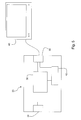
- Figure 5 shows a schematic representation of a system 33 of generating 3D video from a source 2D video.
- the system includes an input 34 to receive a 2D video.
- a processor 36 receives the 2D and serves to process it as described above.
- An output 38 is shown coupled to a television system 40 for display of 3D video.
- Memory 42 may be provided as part of the system for storing the generated 3D video or the received 2D video prior to or during processing. It will be understood that any suitable processor may be used.
- the processor is provided as an ASIC or FPGA programmed or configured to perform the method described above.
- the television system may be any type of television system or monitor.
- the television is a plasma or LCD television system as this type works particularly well with the image processing method described above.
- the system 33 may be integrated into a television so that the television receives 2D video in the normal way but processes this on the fly and generates 3D video for display to a user.
Landscapes
- Engineering & Computer Science (AREA)
- Multimedia (AREA)
- Signal Processing (AREA)
- Testing, Inspecting, Measuring Of Stereoscopic Televisions And Televisions (AREA)
Abstract
Description
- The present invention relates to a method and apparatus for generating a 3D image from a 2D image. In embodiments, the invention relates to method of generating sequences of 3D images from a corresponding sequence of 2D images. In other words, the method in embodiments is for generating 3D video from 2D video.
- Generally, a method is provided for producing three dimensional (referred to as 3D from this point forward) video from two dimensional (referred to as 2D from this point forward) video captured using a single camera. Separate 2D frames are created for each of the left and right eyes of a viewer for one 2D input frame. These separate 2D frames are displayed on a 3D display alternately one after another in a time sharing fashion. An observer wears shutter or polarized glasses depending on the system. When the left eye frame is displayed on the display, the lens in front of the right eye blocks the vision and vice versa. In this manner, different views of the scene are fed to left and right eyes separately. Finally, the human visual system fuses the data coming from both eyes, and the viewer can observe the depth of field on the display.
- In international patent application no
WO-A-90/13848 -
Figure 1 shows schematically how the process ofWO-A-90/13848 2D input frame 2 is received. This is sub-sampled to generate twointermediate frames 4 of the same height but half the width. A combinedframe 6 is then created including both theintermediate frames 4. The combinedframe 6 has the same width and height as theoriginal frame 2. Next a shift is applied to each of the constituent parts of the combinedframe 6 so as to generate a3D output frame 8. - Although the system of
WO-A-90/13848 -
WO-A-98/29860 - The transformations may be performed in the horizontal dimension, the vertical dimension, or a combination of both. After the 3D video stream has been synthesized, it is displayed on an appropriate display device, which might include a multiplexed display device which alternates the viewing of different fields in conjunction with a pair of shuttered glasses. The glasses allow one field to be displayed to one eye of viewer and another field to be displayed to another eye of a viewer.
- There are a number of known methods by which 3D images or video can be generated from a 2D film or image.
US-A-5,739,844 discloses a method by which 3D image data is generated from a 2D film. The method works by taking into account motion parameters associated with objects in the frame in question and then determining a shift for one of the two stereo images in dependence on the motion parameter. -
US-A-5,682,437 relates to a modification on the method ofUS-A-5,739,844 discussed above. It identifies a problem that occurs using the method ofUS-A-5,739,844 when the movement of objects within an input image is at variable speeds such that in some cases an insufficient delay is used in generating a second image for use in producing a 3D output. Means by which the delay may be varied so as to avoid this effect occurring are disclosed. - Next,
US-A-2010/0021141 discloses a method for generating stereoscopic images starting from a 2D video and then creating a number of layers so as to enable the generation of 3D video. In particular, the system relates to a method by which subtitle data may be presented in a 3D manner corresponding to 3D video and so as to avoid the effect of "flat graphics" which appear "to be buried" in stereoscopic video, thus causing displeasure to viewers. -
US-A-6,031,564 discloses a means by which 3D stereoscopic images may be generated from a monoscopic image. Two perspectives are used, the second perspective being generated by "image warping". This is done primarily by identifying objects and their outline shapes, and in the transformation of the outline shapes into new shapes.US-A-6,314,211 discloses apparatus and method for converting a 2D image sequence into a 3D image sequence using a conversion of a motion disparity into a horizontal disparity and subsequent post-processing method. -
US-A-5,796,373 relates to an apparatus and method of using 2D image data for providing view-visual depth, and in particular to the use of a personal computer to provide a stereoscopic display by means of a "shutter-type stereoscopic eye-glasses". Last,US-A-7,064,895 relates to a method by which a stereoscopic image may be observed by a viewer without use of special glasses. - According to a first aspect of the present invention, there is provided a method of generating a 3D image from an
input 2D image by generating at least one shifted 2D image for presentation to a user in combination with theinput 2D image or another shifted image derived from theinput 2D image, the method comprising: receiving aninput 2D image; for a first row of pixels in theinput 2D image, from some selected point along the row mapping all pixels a common number of pixel locations to the left or right thereby shifting the image and forming a shifted image; mapping pixels in locations in theinput 2D image before the predetermined point, a variable number of pixel locations to the left or right to positions in the shifted image; and repeating for other rows in theinput 2D image. - A method is provided by which 3D images can easily and efficiently be generated based on
input 2D images. Consequently a method is also provided for generating 3D video based oninput 2D video, 2D video being effectively made up of a sequence of 2D images. The method includes the steps of, for a row of pixels in the input image determining a point along the row that depends on the amount of "shift" required. All pixels beyond this point are mapped by a common amount to positions in a row in a shifted image. For pixels before this point in the input row, the mapping is not uniform but rather varies. This enables a smooth mapping to be achieved and also avoids the problem of black strips appearing at the side of an image as encountered using conventional methods of generating 3D images from 2D input images. - Preferably, the same transformation is performed on all rows of a 2D input image such that the image as a whole is "shifted".
- Preferably, the variable mapping is determined in dependence on a linear relationship between original position and mapped position. This ensures a smooth filling of the region that would conventionally have been a black strip.
- Preferably, the linear relationship has a constant of proportionality dependent on original pixel position. In other words, the further along a row a pixel's position in the input image, the further along it will be positioned in the shifted or output image. This means that the strip that would conventionally have been black is faithfully filled with the original image data so that the "stretching" of the input image at this point is unlikely to be noticed by a user or viewer. This is particularly the case since the viewer's attention will be on the main body of image where the 3D effect will be generated.
- Preferably, the linear mapping is performed in accordance with some defined algorithm.
- In one example, the following can be used:
- Pin(i) denotes a pixel at position i of the input row
- Pout(i) denotes a pixel at position i of the output row and the shift amount, i.e. pixel correspondence, is defined as

- Pout(i) = Pin(x).
- Preferably, if x is not integer, then the following relationship is used to determine the pixel value within the output row Pout (i)

in which
└ x┘ : greatest integer that is smaller than or equal to x;
┌ x┐ : smallest integer that is greater than or equal to x; and,
- In one example, the
input 2D image has a width of w pixels and the selected point is defined as n in which n <w, the shift amount being α, such that all pixels in theinput 2D image with a position greater than or equal to n are shifted to a new position n + α in the shifted image. - In one example, pixels in the shifted image having a position less than n + α are assigned values in dependence on the pixel values in the
input 2D image of the pixels having position being less than n. - In one example, for pixel positions in the output row for which there is not a direct mapping from a single pixel in the input row, the pixel value is determined on a weighted average.
- In one example, upon receipt of the
input 2D image, down-sampling is performed to generate two images for processing. Preferably, the down-sampling comprises lowpass filtering and then sub-sampling. Each of the down-sampled images is shifted by an amount, so that the two shifted images can be presented to a user. - In one example, the method comprises presenting to a user the shifted 2D image in combination with the
input 2D image or another shifted image derived from theinput 2D image, to thereby generate a 3D image. - According to a second aspect of the present invention, there is provided a method of generating 3D video from 2D video, comprising for each frame of an
input 2D video, generating a 3D image in accordance with the first aspect of the present invention. In other words, whereas the first aspect of the present invention relates generally to generating a 3D image from a 2D image, the second aspect includes the method of the first aspect but relates to its use in generating a 3D video from a 2D video which may be thought of as generating a sequence of 3D images from a sequence ofinput 2D images. - According to a second aspect of the present invention, there is provided apparatus for generating a 3D image from an
input 2D image by generating at least one shifted 2D image for presentation to a user in combination with theinput 2D image or another shifted image derived from theinput 2D image, the apparatus comprising a processor arranged to receive aninput 2D image and for a first row of pixels in theinput 2D image, from some selected point along the row to map all pixels a common number of pixel locations to the left or right thereby shifting the image and forming a shifted image and being further arranged to map pixels in locations in theinput 2D image before the predetermined point, a variable number of pixel locations to the left or right to positions in the shifted image. - Apparatus is provided which serves to easily and efficiently generate 3D images based on
input 2D images. Consequently apparatus is also provided for generating 3D video based oninput 2D video, 2D video being effectively made up of a sequence of 2D images. As will be explained below, the apparatus can form part of a television system or perhaps part of a set top box or TV peripheral which receives a 2D video signal and then provides this to a television for display. - Preferably, the apparatus comprises a memory for storing the 2D input image prior to processing.
- Preferably, the memory is arranged to store the generated 3D image prior to presentation to a user.
- Preferably, the apparatus is arranged to receive an
input 2D video made up of frames each being aninput 2D image and to generate a 3D video by generating a 3D image for each of the received frames. - According to a third aspect of the present invention, there is provided a television set including a display for displaying video and apparatus for generating a 3D video according to the second aspect of the present invention.
- According to a fourth aspect of the present invention, there is provided a method of generating a 3D image from an original 2D image by generating at least one shifted image for presentation to a user in combination with the original 2D image or another shifted image derived from the original 2D image, so as to generate a 3D effect, the method comprising: receiving an original 2D image; for a first row of pixels in the original 2D image, at some predetermined point along the row shifting all pixels a common number of pixel locations to the left or right thereby shifting the image; for pixels in locations before the predetermined point, interpolating values for corresponding positions in the shifted image.
- It will be appreciated that any features expressed herein as being provided "in one example" or as being "preferable" may be provided in combination with any one or more other such features together with any one or more of the aspects of the present invention.
- Embodiments of the present invention will now be described in detail with reference to the accompanying drawings, in which:
-
Figure 1 shows a schematic representation of a method of generating 3D video from 2D video as used inWO-A-90/13848 -
Figure 2 is a schematic representation of a method of generating 3D video from 2D video; -
Figure 3 shows an example of pixel transforms in a row of video as used in a method of generating 3D video from 2D video; -
Figure 4 is a schematic representation of a method of generating 3D video from 2D video; and, -
Figure 5 is a schematic representation of a television system connected to a system for generating 3D video from 2D video. - An example of the present method will now be described with reference to
Figure 2 . Initially, a 2D image orvideo frame 10 is received. Then, left andright eye images - A packed
frame 16 is created in a manner similar to that described above with reference to step 6 ofFigure 1 . In this example, the left and right frames may be presented in a side-by-side manner. However, it will be appreciated that any suitable "packing method" may be used. In one example, the "left" and "right" frames are packed one above the other, i.e. vertically side-by-side instead of horizontally. The specific method of packing used in each case depends on the expected input format in the eventual 3D display. - The method of down-sampling is also changed in dependence on the packing method used. For example, if the frames are packed one above the other then instead of horizontal down-sampling, vertical down-sampling could be used. Another packing method that may be used is a line interleaving method which is mostly used with pattern retarder type polarized panels. A fourth method that may be used is no-packing and no-down-sampling. This may be used if the display panel can support twice frame rate driving. Irrespective of the packing method used, two frames are eventually sent or presented to a viewer's left and right eyes after being unpacked and hence the present method is applicable to all in the same way. Therefore, for the purpose of the present description it will suffice to consider only the side-by-side packing, as a non-limiting example, from this point on.
- Once the side-by-side frame has been produced the problem of the black or vacant strips at the sides is addressed. This is done with the use of a method referred to herein as "linear shift" and serves to prevent black strips at the vertical (or horizontal depending on packing mode) sides of the left and right eye frames.
- The problem of strips at the side of the shifted frames can be understood with reference to
Figure 3 . -
Figure 3 shows a schematic representation of how the problem of black strips at the edges of a frame can arise when 3D video is generated from 2D video using a method such as that described inWO-A-90/13848 input 2D frame, and the corresponding row of shifted frame is referred to as the "output row", as it is a row from anoutput 3D frame. - As can be seen, pixels of the
input row 20 are mapped to the pixels of theoutput row 22 as indicated shown by thearrows 24. When reference is made herein to a first pixel being "mapped to" another pixel, this means that the pixel value of the first pixel is assigned to the position of a second pixel. - The same shift operation is applied to all rows of the original frame. The shift amount is "α" which is greater than zero, so the frame is translated to the right. As the pixels are translated to right, some
pixels 26 at the beginning of theoutput row 22 remain empty. These "missing" pixels are painted black or assigned some neutral value. In the present method linear shifting is used to find values for these missing pixels. - To fill the missing pixels, a linear shift operation is used. In this method, some pixels of the output row are copied directly from the pixels of the input row and some pixels of the output row are calculated as the weighted average of the pixels of the input row.
Figure 4 shows an example of a horizontal linear shift operation for the first row of a frame. As mentioned above, the same shift operation is typically applied to all rows of the frame thereby providing a full frame shift. - Referring to
Figure 4 , aninput row 28 is made up of w pixels in column positions (c) 1 to w. Pixels within this row are to be mapped to positions in the row of an output image. The overall shift amount or mapping required in this example to produce a frame suitable for providing (in combination with another frame) a 3D video effect is defined, as above with reference toFigure 3 , as "α" which is greater than zero. Thus, the image in the frame is translated to the right. InFigure 4 , "s" denotes shift amount. "n" is a number between 1 and w. "i" is a number between 1 and "n+α", to be described in greater detail below. The pixels of the input row are mapped to the pixels of the shifted row as shown by thearrows 32. As can be seen, the shift applied to pixels of the input row is not constant. - Pixels in the input row with column number greater than or equal to n are directly mapped to the respective columns "n+α" of the shifted output row. In other words, the shift applied to each of the pixels in a position greater than or equal to n is α. For the first column (c=1) of the input row, the shift amount is zero. In other words, the pixel in column one of the input row is directly copied to the first column of the shifted output row. For columns between 1 and n, the shift amount increases from 0 to α.
- In other words, the pixel at column "i" in the output row is copied from one column of the input row for all values of c ≥ n and for some values of c<n. for these pixels having positions c < n for which there is no direct copy or mapping available, the value in the output row is calculated as the weighted average of some pixels of the input row. One example of a means by which the weighted average may be calculated will now be described in detail. It will be appreciated though that any suitable means for calculating a weighted average may be used.
- P in(i) denotes the pixel at column i of the input row
- P out(i) denotes the pixel at column i of the output row
- A shift amount "x" is determined as the position of the pixel in the input row that is mapped to a shifted position in the output row. In other words, Pout(i) is defined in some way with respect to the values of the input pixels in the region between c=1 and c=n in the input row.
- The shift may be defined as follows:

- If x is an integer number, then

- For example, if α = 30, and n=30, then the value of the pixel in the output row at
position 6, will be the value of the pixel at position 6x(30/30+30), i.e. 3, in the input row. Hence the value ofpixel 3 from the input row is copied toposition 6 in the output row. The value ofpixel 4 from the input row is copied toposition 8 in the output row, and so on. For these pixels (those with positions c < n), there is therefore a linear relationship between the original position of a pixel in the input row and the position in the output row to which it is written. The constant of proportionality is defined in x above, i.e. determined by the parameters n and α. - Although a linear relationship is defined in this example, it will be understood that other relationships may be defined to determine the mapping of input pixels to output pixels. Indeed, it is preferred that any mapping as determined from a polynomial family may be used, the polynomial family being defined as

- Linear mapping is the specific example when w 1 = 1 and wi = 0 for i = 2 to m.
- If x is not integer, then the following relationship is used to determine the pixel value within the output row Pout (i)

in which
└ x┘: greatest integer that is smaller than or equal to x;
┌ x┐: smallest integer that is greater than or equal to x; and,
- The above described weighted averaging scheme takes into account two samples to produce an output value, i.e. the greatest integer that is smaller than or equal to x and smallest integer that is greater than or equal to x. In some examples, a weighted average can be determined that incorporates more than two samples. Also, if a frame is translated to left, then linear shift block works on the right side of the frame using the same methodology, but in the reverse direction.
- Referring again to
Figure 4 , as can be seen, the gradient of the arrows showing the mapping of pixels from the input row to the output row varies. For pixel at c=1, the arrow is vertical, whereas for pixel c=n, the arrow has the gradient that represents the overall mapping for pixels with c>n. This represents a variation in the shift as explained above. Indeed, whilst the precise gradients are not important as these merely depend on the schematic manner in which the rows and their separation are depicted in the figure, what this does show clearly is that for pixels in the region having value of c<n, the mapping or shift is not uniform, but varies across this region. - Thus, it will be appreciated that values for all pixels in the output row are calculated in a simple and efficient manner in a way that leaves no black strips or null values in the output frame. As explained above, in one example, down-sampling may be performed so as to generate the two images that are to be used in the formation of a 3D image for reach frame within a 2D video. Preferably, no down-sampling is performed and instead the entire input frame is transformed in the manner described above.
- In
WO-A-98/29860 - In contrast the present method and apparatus, serves to trasform a single progressive video input to double progressive video outputs more applicable to present day LCDs, plasmas etc. In preferred embodiments of the present method, all the original image data (except that lost at boundaries due to shifting) on both generated images is used. The present method enables the pushing of the whole frame to the background or foreground, i.e. the left or right in depdnence on image configuration, and management of the problems at boundaries in an efficient and cost effective way.
- Furthermore, in
WO-A-98/29860 -
Figure 5 shows a schematic representation of asystem 33 of generating 3D video from asource 2D video. The system includes aninput 34 to receive a 2D video. Aprocessor 36 receives the 2D and serves to process it as described above. Anoutput 38 is shown coupled to atelevision system 40 for display of 3D video.Memory 42 may be provided as part of the system for storing the generated 3D video or the received 2D video prior to or during processing. It will be understood that any suitable processor may be used. Typically, the processor is provided as an ASIC or FPGA programmed or configured to perform the method described above. The television system may be any type of television system or monitor. - Preferably the television is a plasma or LCD television system as this type works particularly well with the image processing method described above. Furthermore, it will be appreciated that although shown as a separate system, the
system 33 may be integrated into a television so that the television receives 2D video in the normal way but processes this on the fly and generates 3D video for display to a user. - Embodiments of the present invention have been described with particular reference to the examples illustrated. However, it will be appreciated that variations and modifications may be made to the examples described within the scope of the present invention.
Claims (15)
- A method of generating a 3D image from an input 2D image by generating at least one shifted 2D image for presentation to a user in combination with the input 2D image or another shifted image derived from the input 2D image, the method comprising:receiving an input 2D image;for a first row of pixels in the input 2D image, from some selected point along the row mapping all pixels a common number of pixel locations to the left or mapping all pixels a common number of pixel locations to the right thereby shifting the image and forming a shifted image;mapping pixels in locations in the input 2D image before the predetermined point, a variable number of pixel locations to the left or right to positions in the shifted image; andrepeating for other rows in the input 2D image.
- A method according to claim 1, in which the variable mapping is determined in dependence on a linear relationship between original position and mapped position.
- A method according to claim 1, in which the linear relationship has a constant of proportionality dependent on original pixel position.
- A method according to claim 3, in which
Pin(i) denotes a pixel at position i of the input row
Pout(i) denotes a pixel at position i of the output row
and the shift amount is defined
if x is an integer number, then
- A method according to claim 4, in which,
if x is not integer, then the following relationship is used to determine the pixel value within the output row Pout (i)
in which
└ x┘: greatest integer that is smaller than or equal to x;
┌ x┐: smallest integer that is greater than or equal to x; and,
- A method according to any of claims 1 to 5, in which the input 2D image has a width of w pixels and the selected point is defined as n in which n <w, the shift amount being α, such that all pixels in the input 2D image with a position greater than or equal to n are shifted to a new position n + α in the shifted image.
- A method according to claim 6, in which pixels in the shifted image having a position less than n + α are assigned values in dependence on the pixel values in the input 2D image of the pixels having position being less than n.
- A method according to claim 2 or 3, in which for pixel positions in the output row for which there is not a direct mapping from a single pixel in the input row, the pixel value is determined on a weighted average.
- A method according to any of claims 1 to 8, in which upon receipt of the input 2D image, down-sampling is performed to generate two images for processing, each of the down-sampled images being shifted by an amount, so that the two shifted images can be presented to a user.
- A method according to any of claims 1 to 9, comprising presenting to a user the shifted 2D image in combination with the input 2D image or another shifted image derived from the input 2D image, to thereby generate a 3D image.
- A method of generating 3D video from 2D video, comprising for each frame of an input 2D video, generating a 3D image in accordance with the method of any one or more of claims 1 to 10.
- Apparatus for generating a 3D image from an input 2D image by generating at least one shifted 2D image for presentation to a user in combination with the input 2D image or another shifted image derived from the input 2D image, the apparatus comprising a processor arranged to
receive an input 2D image and for a first row of pixels in the input 2D image, from some selected point along the row to map all pixels a common number of pixel locations to the left or right thereby shifting the image and forming a shifted image
and being further arranged to map pixels in locations in the input 2D image before the predetermined point, a variable number of pixel locations to the left or right to positions in the shifted image. - Apparatus according to claim 12, comprising a memory for storing the 2D input image prior to processing and/or storing the generated 3D image prior to presentation to a user.
- Apparatus according to claim 12 or 13, arranged to receive an input 2D video made up of frames each being an input 2D image and to generate a 3D video by generating a 3D image for each of the received frames.
- A television set including a display for displaying video and apparatus for generating a 3D video according to claim 14.
Applications Claiming Priority (1)
| Application Number | Priority Date | Filing Date | Title |
|---|---|---|---|
| TR2011/03444A TR201103444A2 (en) | 2011-04-08 | 2011-04-08 | Method and device for creating a 3D image from a 2D image. |
Publications (3)
| Publication Number | Publication Date |
|---|---|
| EP2509328A2 true EP2509328A2 (en) | 2012-10-10 |
| EP2509328A3 EP2509328A3 (en) | 2015-04-08 |
| EP2509328B1 EP2509328B1 (en) | 2022-01-26 |
Family
ID=46045734
Family Applications (1)
| Application Number | Title | Priority Date | Filing Date |
|---|---|---|---|
| EP12162521.4A Active EP2509328B1 (en) | 2011-04-08 | 2012-03-30 | Method and apparatus for generating a 3d image from a 2d image |
Country Status (3)
| Country | Link |
|---|---|
| EP (1) | EP2509328B1 (en) |
| ES (1) | ES2908403T3 (en) |
| TR (1) | TR201103444A2 (en) |
Citations (9)
| Publication number | Priority date | Publication date | Assignee | Title |
|---|---|---|---|---|
| WO1990013848A1 (en) | 1989-04-28 | 1990-11-15 | Delta System Design Limited | Imaging systems |
| US5682437A (en) | 1994-09-22 | 1997-10-28 | Sanyo Electric Co., Ltd. | Method of converting two-dimensional images into three-dimensional images |
| US5739844A (en) | 1994-02-04 | 1998-04-14 | Sanyo Electric Co. Ltd. | Method of converting two-dimensional image into three-dimensional image |
| WO1998029860A1 (en) | 1996-12-27 | 1998-07-09 | Chequemate International Inc. | System and method for synthesizing three-dimensional video from a two-dimensional video source |
| US5796373A (en) | 1996-10-10 | 1998-08-18 | Artificial Parallax Electronics Corp. | Computerized stereoscopic image system and method of using two-dimensional image for providing a view having visual depth |
| US6031564A (en) | 1997-07-07 | 2000-02-29 | Reveo, Inc. | Method and apparatus for monoscopic to stereoscopic image conversion |
| US6314211B1 (en) | 1997-12-30 | 2001-11-06 | Samsung Electronics Co., Ltd. | Apparatus and method for converting two-dimensional image sequence into three-dimensional image using conversion of motion disparity into horizontal disparity and post-processing method during generation of three-dimensional image |
| US7064895B2 (en) | 2000-08-09 | 2006-06-20 | Canon Kabushiki Kaisha | Stereoscopic image display method and stereoscopic image display apparatus using it |
| US20100021141A1 (en) | 2008-07-24 | 2010-01-28 | Panasonic Corporation | Play back apparatus, playback method and program for playing back 3d video |
Family Cites Families (4)
| Publication number | Priority date | Publication date | Assignee | Title |
|---|---|---|---|---|
| US6590573B1 (en) * | 1983-05-09 | 2003-07-08 | David Michael Geshwind | Interactive computer system for creating three-dimensional image information and for converting two-dimensional image information for three-dimensional display systems |
| CN100576251C (en) * | 2005-04-19 | 2009-12-30 | 皇家飞利浦电子股份有限公司 | Presentation unit, presentation method and image processing device |
| US8471898B2 (en) * | 2008-02-05 | 2013-06-25 | Disney Enterprises, Inc. | Medial axis decomposition of 2D objects to synthesize binocular depth |
| US8502862B2 (en) * | 2009-09-30 | 2013-08-06 | Disney Enterprises, Inc. | Method and system for utilizing pre-existing image layers of a two-dimensional image to create a stereoscopic image |
-
2011
- 2011-04-08 TR TR2011/03444A patent/TR201103444A2/en unknown
-
2012
- 2012-03-30 EP EP12162521.4A patent/EP2509328B1/en active Active
- 2012-03-30 ES ES12162521T patent/ES2908403T3/en active Active
Patent Citations (9)
| Publication number | Priority date | Publication date | Assignee | Title |
|---|---|---|---|---|
| WO1990013848A1 (en) | 1989-04-28 | 1990-11-15 | Delta System Design Limited | Imaging systems |
| US5739844A (en) | 1994-02-04 | 1998-04-14 | Sanyo Electric Co. Ltd. | Method of converting two-dimensional image into three-dimensional image |
| US5682437A (en) | 1994-09-22 | 1997-10-28 | Sanyo Electric Co., Ltd. | Method of converting two-dimensional images into three-dimensional images |
| US5796373A (en) | 1996-10-10 | 1998-08-18 | Artificial Parallax Electronics Corp. | Computerized stereoscopic image system and method of using two-dimensional image for providing a view having visual depth |
| WO1998029860A1 (en) | 1996-12-27 | 1998-07-09 | Chequemate International Inc. | System and method for synthesizing three-dimensional video from a two-dimensional video source |
| US6031564A (en) | 1997-07-07 | 2000-02-29 | Reveo, Inc. | Method and apparatus for monoscopic to stereoscopic image conversion |
| US6314211B1 (en) | 1997-12-30 | 2001-11-06 | Samsung Electronics Co., Ltd. | Apparatus and method for converting two-dimensional image sequence into three-dimensional image using conversion of motion disparity into horizontal disparity and post-processing method during generation of three-dimensional image |
| US7064895B2 (en) | 2000-08-09 | 2006-06-20 | Canon Kabushiki Kaisha | Stereoscopic image display method and stereoscopic image display apparatus using it |
| US20100021141A1 (en) | 2008-07-24 | 2010-01-28 | Panasonic Corporation | Play back apparatus, playback method and program for playing back 3d video |
Also Published As
| Publication number | Publication date |
|---|---|
| TR201103444A2 (en) | 2012-10-22 |
| ES2908403T3 (en) | 2022-04-29 |
| EP2509328B1 (en) | 2022-01-26 |
| EP2509328A3 (en) | 2015-04-08 |
Similar Documents
| Publication | Publication Date | Title |
|---|---|---|
| JP4251952B2 (en) | Stereoscopic image display apparatus and stereoscopic image display method | |
| US8633967B2 (en) | Method and device for the creation of pseudo-holographic images | |
| KR101675041B1 (en) | Resolution enhanced 3d vedio rendering systems and methods | |
| EP1967016B1 (en) | 3d image display method and apparatus | |
| KR20110086079A (en) | Method and system for processing an input three-dimensional video signal | |
| EP1807806B1 (en) | Disparity map | |
| CN102932662B (en) | Single-view-to-multi-view stereoscopic video generation method and method for solving depth information graph and generating disparity map | |
| KR101847675B1 (en) | Method and device for stereo base extension of stereoscopic images and image sequences | |
| US20120044241A1 (en) | Three-dimensional on-screen display imaging system and method | |
| NL2011349C2 (en) | Method for generating, transmitting and receiving stereoscopic images, and related devices. | |
| EP2463853A1 (en) | Image display device, image display system, and image display method | |
| EP2490173B1 (en) | Method for processing a stereoscopic image comprising a black band and corresponding device | |
| US20130050183A1 (en) | System and Method of Rendering Stereoscopic Images | |
| US20120170837A1 (en) | Method and device for generating partial views and/or a stereoscopic image master from a 2d-view for stereoscopic playback | |
| JP2010278743A (en) | Three-dimensional video display apparatus and three-dimensional video display method | |
| US20140132743A1 (en) | Apparatus and method for encoding/decoding mutli-view images | |
| KR102180068B1 (en) | Method and device of generating multi-view image with resolution scaling function | |
| EP2509328B1 (en) | Method and apparatus for generating a 3d image from a 2d image | |
| US10009590B2 (en) | Method for reducing the size of a stereoscopic image | |
| JP2012138655A (en) | Image processing device and image processing method | |
| WO2007017834A3 (en) | Disparity value generator | |
| JP2011124802A (en) | Device and method for generating stereoscopic video | |
| EP2547109A1 (en) | Automatic conversion in a 2D/3D compatible mode | |
| KR102492367B1 (en) | Image data generating method and stereoscopic image display system using the same | |
| US8947507B2 (en) | Method of processing 3D images, and corresponding system including the formulation of missing pixels using windows of details from first and second views |
Legal Events
| Date | Code | Title | Description |
|---|---|---|---|
| PUAI | Public reference made under article 153(3) epc to a published international application that has entered the european phase |
Free format text: ORIGINAL CODE: 0009012 |
|
| AK | Designated contracting states |
Kind code of ref document: A2 Designated state(s): AL AT BE BG CH CY CZ DE DK EE ES FI FR GB GR HR HU IE IS IT LI LT LU LV MC MK MT NL NO PL PT RO RS SE SI SK SM TR |
|
| AX | Request for extension of the european patent |
Extension state: BA ME |
|
| RIN1 | Information on inventor provided before grant (corrected) |
Inventor name: BASTUG, AHMET Inventor name: OZER, NURI Inventor name: OZDEMIR, HUSEYIN |
|
| PUAL | Search report despatched |
Free format text: ORIGINAL CODE: 0009013 |
|
| AK | Designated contracting states |
Kind code of ref document: A3 Designated state(s): AL AT BE BG CH CY CZ DE DK EE ES FI FR GB GR HR HU IE IS IT LI LT LU LV MC MK MT NL NO PL PT RO RS SE SI SK SM TR |
|
| AX | Request for extension of the european patent |
Extension state: BA ME |
|
| RIC1 | Information provided on ipc code assigned before grant |
Ipc: H04N 13/02 20060101AFI20150303BHEP |
|
| 17P | Request for examination filed |
Effective date: 20151008 |
|
| RBV | Designated contracting states (corrected) |
Designated state(s): AL AT BE BG CH CY CZ DE DK EE ES FI FR GB GR HR HU IE IS IT LI LT LU LV MC MK MT NL NO PL PT RO RS SE SI SK SM TR |
|
| STAA | Information on the status of an ep patent application or granted ep patent |
Free format text: STATUS: EXAMINATION IS IN PROGRESS |
|
| 17Q | First examination report despatched |
Effective date: 20170127 |
|
| REG | Reference to a national code |
Ref country code: DE Ref legal event code: R079 Ref document number: 602012077574 Country of ref document: DE Free format text: PREVIOUS MAIN CLASS: H04N0013020000 Ipc: H04N0013000000 |
|
| RIC1 | Information provided on ipc code assigned before grant |
Ipc: H04N 13/00 20180101AFI20191126BHEP |
|
| GRAP | Despatch of communication of intention to grant a patent |
Free format text: ORIGINAL CODE: EPIDOSNIGR1 |
|
| STAA | Information on the status of an ep patent application or granted ep patent |
Free format text: STATUS: GRANT OF PATENT IS INTENDED |
|
| INTG | Intention to grant announced |
Effective date: 20211018 |
|
| GRAS | Grant fee paid |
Free format text: ORIGINAL CODE: EPIDOSNIGR3 |
|
| GRAA | (expected) grant |
Free format text: ORIGINAL CODE: 0009210 |
|
| STAA | Information on the status of an ep patent application or granted ep patent |
Free format text: STATUS: THE PATENT HAS BEEN GRANTED |
|
| AK | Designated contracting states |
Kind code of ref document: B1 Designated state(s): AL AT BE BG CH CY CZ DE DK EE ES FI FR GB GR HR HU IE IS IT LI LT LU LV MC MK MT NL NO PL PT RO RS SE SI SK SM TR |
|
| REG | Reference to a national code |
Ref country code: GB Ref legal event code: FG4D |
|
| REG | Reference to a national code |
Ref country code: CH Ref legal event code: EP |
|
| REG | Reference to a national code |
Ref country code: AT Ref legal event code: REF Ref document number: 1466197 Country of ref document: AT Kind code of ref document: T Effective date: 20220215 |
|
| REG | Reference to a national code |
Ref country code: IE Ref legal event code: FG4D |
|
| REG | Reference to a national code |
Ref country code: DE Ref legal event code: R096 Ref document number: 602012077574 Country of ref document: DE |
|
| REG | Reference to a national code |
Ref country code: ES Ref legal event code: FG2A Ref document number: 2908403 Country of ref document: ES Kind code of ref document: T3 Effective date: 20220429 |
|
| REG | Reference to a national code |
Ref country code: LT Ref legal event code: MG9D |
|
| REG | Reference to a national code |
Ref country code: NL Ref legal event code: MP Effective date: 20220126 |
|
| REG | Reference to a national code |
Ref country code: AT Ref legal event code: MK05 Ref document number: 1466197 Country of ref document: AT Kind code of ref document: T Effective date: 20220126 |
|
| PG25 | Lapsed in a contracting state [announced via postgrant information from national office to epo] |
Ref country code: NL Free format text: LAPSE BECAUSE OF FAILURE TO SUBMIT A TRANSLATION OF THE DESCRIPTION OR TO PAY THE FEE WITHIN THE PRESCRIBED TIME-LIMIT Effective date: 20220126 |
|
| PG25 | Lapsed in a contracting state [announced via postgrant information from national office to epo] |
Ref country code: SE Free format text: LAPSE BECAUSE OF FAILURE TO SUBMIT A TRANSLATION OF THE DESCRIPTION OR TO PAY THE FEE WITHIN THE PRESCRIBED TIME-LIMIT Effective date: 20220126 Ref country code: RS Free format text: LAPSE BECAUSE OF FAILURE TO SUBMIT A TRANSLATION OF THE DESCRIPTION OR TO PAY THE FEE WITHIN THE PRESCRIBED TIME-LIMIT Effective date: 20220126 Ref country code: PT Free format text: LAPSE BECAUSE OF FAILURE TO SUBMIT A TRANSLATION OF THE DESCRIPTION OR TO PAY THE FEE WITHIN THE PRESCRIBED TIME-LIMIT Effective date: 20220526 Ref country code: NO Free format text: LAPSE BECAUSE OF FAILURE TO SUBMIT A TRANSLATION OF THE DESCRIPTION OR TO PAY THE FEE WITHIN THE PRESCRIBED TIME-LIMIT Effective date: 20220426 Ref country code: LT Free format text: LAPSE BECAUSE OF FAILURE TO SUBMIT A TRANSLATION OF THE DESCRIPTION OR TO PAY THE FEE WITHIN THE PRESCRIBED TIME-LIMIT Effective date: 20220126 Ref country code: HR Free format text: LAPSE BECAUSE OF FAILURE TO SUBMIT A TRANSLATION OF THE DESCRIPTION OR TO PAY THE FEE WITHIN THE PRESCRIBED TIME-LIMIT Effective date: 20220126 Ref country code: BG Free format text: LAPSE BECAUSE OF FAILURE TO SUBMIT A TRANSLATION OF THE DESCRIPTION OR TO PAY THE FEE WITHIN THE PRESCRIBED TIME-LIMIT Effective date: 20220426 |
|
| PG25 | Lapsed in a contracting state [announced via postgrant information from national office to epo] |
Ref country code: PL Free format text: LAPSE BECAUSE OF FAILURE TO SUBMIT A TRANSLATION OF THE DESCRIPTION OR TO PAY THE FEE WITHIN THE PRESCRIBED TIME-LIMIT Effective date: 20220126 Ref country code: LV Free format text: LAPSE BECAUSE OF FAILURE TO SUBMIT A TRANSLATION OF THE DESCRIPTION OR TO PAY THE FEE WITHIN THE PRESCRIBED TIME-LIMIT Effective date: 20220126 Ref country code: GR Free format text: LAPSE BECAUSE OF FAILURE TO SUBMIT A TRANSLATION OF THE DESCRIPTION OR TO PAY THE FEE WITHIN THE PRESCRIBED TIME-LIMIT Effective date: 20220427 Ref country code: FI Free format text: LAPSE BECAUSE OF FAILURE TO SUBMIT A TRANSLATION OF THE DESCRIPTION OR TO PAY THE FEE WITHIN THE PRESCRIBED TIME-LIMIT Effective date: 20220126 Ref country code: AT Free format text: LAPSE BECAUSE OF FAILURE TO SUBMIT A TRANSLATION OF THE DESCRIPTION OR TO PAY THE FEE WITHIN THE PRESCRIBED TIME-LIMIT Effective date: 20220126 |
|
| PG25 | Lapsed in a contracting state [announced via postgrant information from national office to epo] |
Ref country code: IS Free format text: LAPSE BECAUSE OF FAILURE TO SUBMIT A TRANSLATION OF THE DESCRIPTION OR TO PAY THE FEE WITHIN THE PRESCRIBED TIME-LIMIT Effective date: 20220526 |
|
| REG | Reference to a national code |
Ref country code: DE Ref legal event code: R097 Ref document number: 602012077574 Country of ref document: DE |
|
| PG25 | Lapsed in a contracting state [announced via postgrant information from national office to epo] |
Ref country code: SM Free format text: LAPSE BECAUSE OF FAILURE TO SUBMIT A TRANSLATION OF THE DESCRIPTION OR TO PAY THE FEE WITHIN THE PRESCRIBED TIME-LIMIT Effective date: 20220126 Ref country code: SK Free format text: LAPSE BECAUSE OF FAILURE TO SUBMIT A TRANSLATION OF THE DESCRIPTION OR TO PAY THE FEE WITHIN THE PRESCRIBED TIME-LIMIT Effective date: 20220126 Ref country code: RO Free format text: LAPSE BECAUSE OF FAILURE TO SUBMIT A TRANSLATION OF THE DESCRIPTION OR TO PAY THE FEE WITHIN THE PRESCRIBED TIME-LIMIT Effective date: 20220126 Ref country code: MC Free format text: LAPSE BECAUSE OF FAILURE TO SUBMIT A TRANSLATION OF THE DESCRIPTION OR TO PAY THE FEE WITHIN THE PRESCRIBED TIME-LIMIT Effective date: 20220126 Ref country code: EE Free format text: LAPSE BECAUSE OF FAILURE TO SUBMIT A TRANSLATION OF THE DESCRIPTION OR TO PAY THE FEE WITHIN THE PRESCRIBED TIME-LIMIT Effective date: 20220126 Ref country code: DK Free format text: LAPSE BECAUSE OF FAILURE TO SUBMIT A TRANSLATION OF THE DESCRIPTION OR TO PAY THE FEE WITHIN THE PRESCRIBED TIME-LIMIT Effective date: 20220126 Ref country code: CZ Free format text: LAPSE BECAUSE OF FAILURE TO SUBMIT A TRANSLATION OF THE DESCRIPTION OR TO PAY THE FEE WITHIN THE PRESCRIBED TIME-LIMIT Effective date: 20220126 |
|
| REG | Reference to a national code |
Ref country code: CH Ref legal event code: PL |
|
| PG25 | Lapsed in a contracting state [announced via postgrant information from national office to epo] |
Ref country code: AL Free format text: LAPSE BECAUSE OF FAILURE TO SUBMIT A TRANSLATION OF THE DESCRIPTION OR TO PAY THE FEE WITHIN THE PRESCRIBED TIME-LIMIT Effective date: 20220126 |
|
| PLBE | No opposition filed within time limit |
Free format text: ORIGINAL CODE: 0009261 |
|
| STAA | Information on the status of an ep patent application or granted ep patent |
Free format text: STATUS: NO OPPOSITION FILED WITHIN TIME LIMIT |
|
| REG | Reference to a national code |
Ref country code: BE Ref legal event code: MM Effective date: 20220331 |
|
| 26N | No opposition filed |
Effective date: 20221027 |
|
| PG25 | Lapsed in a contracting state [announced via postgrant information from national office to epo] |
Ref country code: LU Free format text: LAPSE BECAUSE OF NON-PAYMENT OF DUE FEES Effective date: 20220330 Ref country code: LI Free format text: LAPSE BECAUSE OF NON-PAYMENT OF DUE FEES Effective date: 20220331 Ref country code: IE Free format text: LAPSE BECAUSE OF NON-PAYMENT OF DUE FEES Effective date: 20220330 Ref country code: CH Free format text: LAPSE BECAUSE OF NON-PAYMENT OF DUE FEES Effective date: 20220331 |
|
| PG25 | Lapsed in a contracting state [announced via postgrant information from national office to epo] |
Ref country code: SI Free format text: LAPSE BECAUSE OF FAILURE TO SUBMIT A TRANSLATION OF THE DESCRIPTION OR TO PAY THE FEE WITHIN THE PRESCRIBED TIME-LIMIT Effective date: 20220126 Ref country code: BE Free format text: LAPSE BECAUSE OF NON-PAYMENT OF DUE FEES Effective date: 20220331 |
|
| PG25 | Lapsed in a contracting state [announced via postgrant information from national office to epo] |
Ref country code: HU Free format text: LAPSE BECAUSE OF FAILURE TO SUBMIT A TRANSLATION OF THE DESCRIPTION OR TO PAY THE FEE WITHIN THE PRESCRIBED TIME-LIMIT; INVALID AB INITIO Effective date: 20120330 |
|
| PG25 | Lapsed in a contracting state [announced via postgrant information from national office to epo] |
Ref country code: MK Free format text: LAPSE BECAUSE OF FAILURE TO SUBMIT A TRANSLATION OF THE DESCRIPTION OR TO PAY THE FEE WITHIN THE PRESCRIBED TIME-LIMIT Effective date: 20220126 Ref country code: CY Free format text: LAPSE BECAUSE OF FAILURE TO SUBMIT A TRANSLATION OF THE DESCRIPTION OR TO PAY THE FEE WITHIN THE PRESCRIBED TIME-LIMIT Effective date: 20220126 |
|
| PG25 | Lapsed in a contracting state [announced via postgrant information from national office to epo] |
Ref country code: MT Free format text: LAPSE BECAUSE OF FAILURE TO SUBMIT A TRANSLATION OF THE DESCRIPTION OR TO PAY THE FEE WITHIN THE PRESCRIBED TIME-LIMIT Effective date: 20220126 |
|
| PGFP | Annual fee paid to national office [announced via postgrant information from national office to epo] |
Ref country code: DE Payment date: 20250319 Year of fee payment: 14 |
|
| PGFP | Annual fee paid to national office [announced via postgrant information from national office to epo] |
Ref country code: FR Payment date: 20250325 Year of fee payment: 14 |
|
| PGFP | Annual fee paid to national office [announced via postgrant information from national office to epo] |
Ref country code: IT Payment date: 20250325 Year of fee payment: 14 Ref country code: GB Payment date: 20250321 Year of fee payment: 14 |
|
| PGFP | Annual fee paid to national office [announced via postgrant information from national office to epo] |
Ref country code: ES Payment date: 20250425 Year of fee payment: 14 |
|
| PGFP | Annual fee paid to national office [announced via postgrant information from national office to epo] |
Ref country code: TR Payment date: 20260327 Year of fee payment: 15 |