EP2509059A1 - Display device and meter device using same - Google Patents
Display device and meter device using same Download PDFInfo
- Publication number
- EP2509059A1 EP2509059A1 EP09851677A EP09851677A EP2509059A1 EP 2509059 A1 EP2509059 A1 EP 2509059A1 EP 09851677 A EP09851677 A EP 09851677A EP 09851677 A EP09851677 A EP 09851677A EP 2509059 A1 EP2509059 A1 EP 2509059A1
- Authority
- EP
- European Patent Office
- Prior art keywords
- light
- color filter
- display
- display device
- emitting
- Prior art date
- Legal status (The legal status is an assumption and is not a legal conclusion. Google has not performed a legal analysis and makes no representation as to the accuracy of the status listed.)
- Granted
Links
Images


Classifications
-
- B—PERFORMING OPERATIONS; TRANSPORTING
- B60—VEHICLES IN GENERAL
- B60K—ARRANGEMENT OR MOUNTING OF PROPULSION UNITS OR OF TRANSMISSIONS IN VEHICLES; ARRANGEMENT OR MOUNTING OF PLURAL DIVERSE PRIME-MOVERS IN VEHICLES; AUXILIARY DRIVES FOR VEHICLES; INSTRUMENTATION OR DASHBOARDS FOR VEHICLES; ARRANGEMENTS IN CONNECTION WITH COOLING, AIR INTAKE, GAS EXHAUST OR FUEL SUPPLY OF PROPULSION UNITS IN VEHICLES
- B60K35/00—Instruments specially adapted for vehicles; Arrangement of instruments in or on vehicles
- B60K35/60—Instruments characterised by their location or relative disposition in or on vehicles
-
- B—PERFORMING OPERATIONS; TRANSPORTING
- B60—VEHICLES IN GENERAL
- B60Q—ARRANGEMENT OF SIGNALLING OR LIGHTING DEVICES, THE MOUNTING OR SUPPORTING THEREOF OR CIRCUITS THEREFOR, FOR VEHICLES IN GENERAL
- B60Q3/00—Arrangement of lighting devices for vehicle interiors; Lighting devices specially adapted for vehicle interiors
- B60Q3/10—Arrangement of lighting devices for vehicle interiors; Lighting devices specially adapted for vehicle interiors for dashboards
-
- B—PERFORMING OPERATIONS; TRANSPORTING
- B60—VEHICLES IN GENERAL
- B60K—ARRANGEMENT OR MOUNTING OF PROPULSION UNITS OR OF TRANSMISSIONS IN VEHICLES; ARRANGEMENT OR MOUNTING OF PLURAL DIVERSE PRIME-MOVERS IN VEHICLES; AUXILIARY DRIVES FOR VEHICLES; INSTRUMENTATION OR DASHBOARDS FOR VEHICLES; ARRANGEMENTS IN CONNECTION WITH COOLING, AIR INTAKE, GAS EXHAUST OR FUEL SUPPLY OF PROPULSION UNITS IN VEHICLES
- B60K35/00—Instruments specially adapted for vehicles; Arrangement of instruments in or on vehicles
- B60K35/20—Output arrangements, i.e. from vehicle to user, associated with vehicle functions or specially adapted therefor
- B60K35/21—Output arrangements, i.e. from vehicle to user, associated with vehicle functions or specially adapted therefor using visual output, e.g. blinking lights or matrix displays
-
- B—PERFORMING OPERATIONS; TRANSPORTING
- B60—VEHICLES IN GENERAL
- B60K—ARRANGEMENT OR MOUNTING OF PROPULSION UNITS OR OF TRANSMISSIONS IN VEHICLES; ARRANGEMENT OR MOUNTING OF PLURAL DIVERSE PRIME-MOVERS IN VEHICLES; AUXILIARY DRIVES FOR VEHICLES; INSTRUMENTATION OR DASHBOARDS FOR VEHICLES; ARRANGEMENTS IN CONNECTION WITH COOLING, AIR INTAKE, GAS EXHAUST OR FUEL SUPPLY OF PROPULSION UNITS IN VEHICLES
- B60K35/00—Instruments specially adapted for vehicles; Arrangement of instruments in or on vehicles
- B60K35/20—Output arrangements, i.e. from vehicle to user, associated with vehicle functions or specially adapted therefor
- B60K35/28—Output arrangements, i.e. from vehicle to user, associated with vehicle functions or specially adapted therefor characterised by the type of the output information, e.g. video entertainment or vehicle dynamics information; characterised by the purpose of the output information, e.g. for attracting the attention of the driver
-
- B—PERFORMING OPERATIONS; TRANSPORTING
- B60—VEHICLES IN GENERAL
- B60K—ARRANGEMENT OR MOUNTING OF PROPULSION UNITS OR OF TRANSMISSIONS IN VEHICLES; ARRANGEMENT OR MOUNTING OF PLURAL DIVERSE PRIME-MOVERS IN VEHICLES; AUXILIARY DRIVES FOR VEHICLES; INSTRUMENTATION OR DASHBOARDS FOR VEHICLES; ARRANGEMENTS IN CONNECTION WITH COOLING, AIR INTAKE, GAS EXHAUST OR FUEL SUPPLY OF PROPULSION UNITS IN VEHICLES
- B60K35/00—Instruments specially adapted for vehicles; Arrangement of instruments in or on vehicles
- B60K35/20—Output arrangements, i.e. from vehicle to user, associated with vehicle functions or specially adapted therefor
- B60K35/29—Instruments characterised by the way in which information is handled, e.g. showing information on plural displays or prioritising information according to driving conditions
-
- B—PERFORMING OPERATIONS; TRANSPORTING
- B60—VEHICLES IN GENERAL
- B60K—ARRANGEMENT OR MOUNTING OF PROPULSION UNITS OR OF TRANSMISSIONS IN VEHICLES; ARRANGEMENT OR MOUNTING OF PLURAL DIVERSE PRIME-MOVERS IN VEHICLES; AUXILIARY DRIVES FOR VEHICLES; INSTRUMENTATION OR DASHBOARDS FOR VEHICLES; ARRANGEMENTS IN CONNECTION WITH COOLING, AIR INTAKE, GAS EXHAUST OR FUEL SUPPLY OF PROPULSION UNITS IN VEHICLES
- B60K35/00—Instruments specially adapted for vehicles; Arrangement of instruments in or on vehicles
- B60K35/50—Instruments characterised by their means of attachment to or integration in the vehicle
-
- G—PHYSICS
- G01—MEASURING; TESTING
- G01D—MEASURING NOT SPECIALLY ADAPTED FOR A SPECIFIC VARIABLE; ARRANGEMENTS FOR MEASURING TWO OR MORE VARIABLES NOT COVERED IN A SINGLE OTHER SUBCLASS; TARIFF METERING APPARATUS; MEASURING OR TESTING NOT OTHERWISE PROVIDED FOR
- G01D11/00—Component parts of measuring arrangements not specially adapted for a specific variable
- G01D11/28—Structurally-combined illuminating devices
-
- B—PERFORMING OPERATIONS; TRANSPORTING
- B60—VEHICLES IN GENERAL
- B60K—ARRANGEMENT OR MOUNTING OF PROPULSION UNITS OR OF TRANSMISSIONS IN VEHICLES; ARRANGEMENT OR MOUNTING OF PLURAL DIVERSE PRIME-MOVERS IN VEHICLES; AUXILIARY DRIVES FOR VEHICLES; INSTRUMENTATION OR DASHBOARDS FOR VEHICLES; ARRANGEMENTS IN CONNECTION WITH COOLING, AIR INTAKE, GAS EXHAUST OR FUEL SUPPLY OF PROPULSION UNITS IN VEHICLES
- B60K2360/00—Indexing scheme associated with groups B60K35/00 or B60K37/00 relating to details of instruments or dashboards
- B60K2360/18—Information management
- B60K2360/188—Displaying information using colour changes
-
- B—PERFORMING OPERATIONS; TRANSPORTING
- B60—VEHICLES IN GENERAL
- B60K—ARRANGEMENT OR MOUNTING OF PROPULSION UNITS OR OF TRANSMISSIONS IN VEHICLES; ARRANGEMENT OR MOUNTING OF PLURAL DIVERSE PRIME-MOVERS IN VEHICLES; AUXILIARY DRIVES FOR VEHICLES; INSTRUMENTATION OR DASHBOARDS FOR VEHICLES; ARRANGEMENTS IN CONNECTION WITH COOLING, AIR INTAKE, GAS EXHAUST OR FUEL SUPPLY OF PROPULSION UNITS IN VEHICLES
- B60K2360/00—Indexing scheme associated with groups B60K35/00 or B60K37/00 relating to details of instruments or dashboards
- B60K2360/20—Optical features of instruments
-
- B—PERFORMING OPERATIONS; TRANSPORTING
- B60—VEHICLES IN GENERAL
- B60K—ARRANGEMENT OR MOUNTING OF PROPULSION UNITS OR OF TRANSMISSIONS IN VEHICLES; ARRANGEMENT OR MOUNTING OF PLURAL DIVERSE PRIME-MOVERS IN VEHICLES; AUXILIARY DRIVES FOR VEHICLES; INSTRUMENTATION OR DASHBOARDS FOR VEHICLES; ARRANGEMENTS IN CONNECTION WITH COOLING, AIR INTAKE, GAS EXHAUST OR FUEL SUPPLY OF PROPULSION UNITS IN VEHICLES
- B60K2360/00—Indexing scheme associated with groups B60K35/00 or B60K37/00 relating to details of instruments or dashboards
- B60K2360/20—Optical features of instruments
- B60K2360/23—Optical features of instruments using reflectors
-
- B—PERFORMING OPERATIONS; TRANSPORTING
- B60—VEHICLES IN GENERAL
- B60K—ARRANGEMENT OR MOUNTING OF PROPULSION UNITS OR OF TRANSMISSIONS IN VEHICLES; ARRANGEMENT OR MOUNTING OF PLURAL DIVERSE PRIME-MOVERS IN VEHICLES; AUXILIARY DRIVES FOR VEHICLES; INSTRUMENTATION OR DASHBOARDS FOR VEHICLES; ARRANGEMENTS IN CONNECTION WITH COOLING, AIR INTAKE, GAS EXHAUST OR FUEL SUPPLY OF PROPULSION UNITS IN VEHICLES
- B60K2360/00—Indexing scheme associated with groups B60K35/00 or B60K37/00 relating to details of instruments or dashboards
- B60K2360/20—Optical features of instruments
- B60K2360/25—Optical features of instruments using filters
-
- B—PERFORMING OPERATIONS; TRANSPORTING
- B60—VEHICLES IN GENERAL
- B60K—ARRANGEMENT OR MOUNTING OF PROPULSION UNITS OR OF TRANSMISSIONS IN VEHICLES; ARRANGEMENT OR MOUNTING OF PLURAL DIVERSE PRIME-MOVERS IN VEHICLES; AUXILIARY DRIVES FOR VEHICLES; INSTRUMENTATION OR DASHBOARDS FOR VEHICLES; ARRANGEMENTS IN CONNECTION WITH COOLING, AIR INTAKE, GAS EXHAUST OR FUEL SUPPLY OF PROPULSION UNITS IN VEHICLES
- B60K2360/00—Indexing scheme associated with groups B60K35/00 or B60K37/00 relating to details of instruments or dashboards
- B60K2360/20—Optical features of instruments
- B60K2360/33—Illumination features
-
- B—PERFORMING OPERATIONS; TRANSPORTING
- B60—VEHICLES IN GENERAL
- B60K—ARRANGEMENT OR MOUNTING OF PROPULSION UNITS OR OF TRANSMISSIONS IN VEHICLES; ARRANGEMENT OR MOUNTING OF PLURAL DIVERSE PRIME-MOVERS IN VEHICLES; AUXILIARY DRIVES FOR VEHICLES; INSTRUMENTATION OR DASHBOARDS FOR VEHICLES; ARRANGEMENTS IN CONNECTION WITH COOLING, AIR INTAKE, GAS EXHAUST OR FUEL SUPPLY OF PROPULSION UNITS IN VEHICLES
- B60K2360/00—Indexing scheme associated with groups B60K35/00 or B60K37/00 relating to details of instruments or dashboards
- B60K2360/20—Optical features of instruments
- B60K2360/33—Illumination features
- B60K2360/332—Light emitting diodes
-
- B—PERFORMING OPERATIONS; TRANSPORTING
- B60—VEHICLES IN GENERAL
- B60K—ARRANGEMENT OR MOUNTING OF PROPULSION UNITS OR OF TRANSMISSIONS IN VEHICLES; ARRANGEMENT OR MOUNTING OF PLURAL DIVERSE PRIME-MOVERS IN VEHICLES; AUXILIARY DRIVES FOR VEHICLES; INSTRUMENTATION OR DASHBOARDS FOR VEHICLES; ARRANGEMENTS IN CONNECTION WITH COOLING, AIR INTAKE, GAS EXHAUST OR FUEL SUPPLY OF PROPULSION UNITS IN VEHICLES
- B60K2360/00—Indexing scheme associated with groups B60K35/00 or B60K37/00 relating to details of instruments or dashboards
- B60K2360/20—Optical features of instruments
- B60K2360/33—Illumination features
- B60K2360/34—Backlit symbols
-
- B—PERFORMING OPERATIONS; TRANSPORTING
- B60—VEHICLES IN GENERAL
- B60K—ARRANGEMENT OR MOUNTING OF PROPULSION UNITS OR OF TRANSMISSIONS IN VEHICLES; ARRANGEMENT OR MOUNTING OF PLURAL DIVERSE PRIME-MOVERS IN VEHICLES; AUXILIARY DRIVES FOR VEHICLES; INSTRUMENTATION OR DASHBOARDS FOR VEHICLES; ARRANGEMENTS IN CONNECTION WITH COOLING, AIR INTAKE, GAS EXHAUST OR FUEL SUPPLY OF PROPULSION UNITS IN VEHICLES
- B60K2360/00—Indexing scheme associated with groups B60K35/00 or B60K37/00 relating to details of instruments or dashboards
- B60K2360/20—Optical features of instruments
- B60K2360/33—Illumination features
- B60K2360/341—Illumination of dials
-
- B—PERFORMING OPERATIONS; TRANSPORTING
- B60—VEHICLES IN GENERAL
- B60K—ARRANGEMENT OR MOUNTING OF PROPULSION UNITS OR OF TRANSMISSIONS IN VEHICLES; ARRANGEMENT OR MOUNTING OF PLURAL DIVERSE PRIME-MOVERS IN VEHICLES; AUXILIARY DRIVES FOR VEHICLES; INSTRUMENTATION OR DASHBOARDS FOR VEHICLES; ARRANGEMENTS IN CONNECTION WITH COOLING, AIR INTAKE, GAS EXHAUST OR FUEL SUPPLY OF PROPULSION UNITS IN VEHICLES
- B60K2360/00—Indexing scheme associated with groups B60K35/00 or B60K37/00 relating to details of instruments or dashboards
- B60K2360/20—Optical features of instruments
- B60K2360/33—Illumination features
- B60K2360/343—Illumination of matrix displays
-
- B—PERFORMING OPERATIONS; TRANSPORTING
- B60—VEHICLES IN GENERAL
- B60K—ARRANGEMENT OR MOUNTING OF PROPULSION UNITS OR OF TRANSMISSIONS IN VEHICLES; ARRANGEMENT OR MOUNTING OF PLURAL DIVERSE PRIME-MOVERS IN VEHICLES; AUXILIARY DRIVES FOR VEHICLES; INSTRUMENTATION OR DASHBOARDS FOR VEHICLES; ARRANGEMENTS IN CONNECTION WITH COOLING, AIR INTAKE, GAS EXHAUST OR FUEL SUPPLY OF PROPULSION UNITS IN VEHICLES
- B60K2360/00—Indexing scheme associated with groups B60K35/00 or B60K37/00 relating to details of instruments or dashboards
- B60K2360/20—Optical features of instruments
- B60K2360/33—Illumination features
- B60K2360/349—Adjustment of brightness
-
- B—PERFORMING OPERATIONS; TRANSPORTING
- B60—VEHICLES IN GENERAL
- B60K—ARRANGEMENT OR MOUNTING OF PROPULSION UNITS OR OF TRANSMISSIONS IN VEHICLES; ARRANGEMENT OR MOUNTING OF PLURAL DIVERSE PRIME-MOVERS IN VEHICLES; AUXILIARY DRIVES FOR VEHICLES; INSTRUMENTATION OR DASHBOARDS FOR VEHICLES; ARRANGEMENTS IN CONNECTION WITH COOLING, AIR INTAKE, GAS EXHAUST OR FUEL SUPPLY OF PROPULSION UNITS IN VEHICLES
- B60K2360/00—Indexing scheme associated with groups B60K35/00 or B60K37/00 relating to details of instruments or dashboards
- B60K2360/60—Structural details of dashboards or instruments
- B60K2360/68—Features of instruments
- B60K2360/693—Cover plate features
-
- G—PHYSICS
- G09—EDUCATION; CRYPTOGRAPHY; DISPLAY; ADVERTISING; SEALS
- G09F—DISPLAYING; ADVERTISING; SIGNS; LABELS OR NAME-PLATES; SEALS
- G09F13/00—Illuminated signs; Luminous advertising
- G09F13/04—Signs, boards or panels, illuminated from behind the insignia
Definitions
- the present invention relates to a display device used in a meter device, which displays travelling states such as vehicle speed in a passenger vehicle or the like, and a meter device using the display device.
- Patent Documents 1 to 3 Conventionally, for this type of display devices, configurations as disclosed in Patent Documents 1 to 3 have been proposed.
- Patent Document 1 In a conventional configuration described in Patent Document 1, a plurality of panel switches are arranged around a liquid crystal panel, and a light guide lens is arranged between the liquid crystal panel and the panel switches. Light from the liquid crystal panel is guided to the panel switches via the light guide lens to illuminate the panel switches. Thus, in Patent Document 1, a light source dedicated to illuminate the panel switches is not required.
- a light control means is provided between a plurality of light sources for vehicle speed display and a plurality of light sources for a shift range display.
- the light control means allows light from the light sources for vehicle speed display to be radiated to a shift range display, which serves as backlight for the shift range display.
- light from the light sources for the shift range display is prevented from being radiated to the vehicle speed display, thereby preventing illumination unevenness in the vehicle speed display.
- a front surface of a light shielding case having a meter therein is coated with a transparent case.
- a corner portion between a front wall portion and a side wall portion of the transparent case has a reflection portion for reflecting external light (light of a head lamp) entering from an edge of the side wall portion outward without allowing the light to pass to the front wall portion.
- This reflection portion shields the external light entering the light shielding case through the transparent case, thereby suppressing illumination unevenness in a meter display.
- a reflecting mirror is provided at the rotational center of an indicator of a tachometer, and display light indicating vehicle travelling speed is emitted from a display to the reflecting mirror through a smoke glass so that the driver can see the travelling speed from display reflected by reflected light.
- the whole of the panel switches is illuminated by light from the liquid crystal panel. Illumination of the panel switches in Patent Document 1 utilizes light of a liquid crystal display screen. Accordingly, the light amount of the switches depends on the light amount of the backlight for the liquid crystal screen to display the switches. Thus, when it is attempted to increase the light amount of the switches, the liquid crystal display screen becomes too bright. Accordingly, in the case of adopting this configuration for decorative illumination, it is difficult to obtain a desired decorative design due to limitations by brightness of the liquid crystal display screen or the like. Moreover, in the configuration described in Patent Document 1, an area for ensuring switch light is required in the liquid crystal screen, resulting in an increase in the whole of the liquid crystal display device in size. Further, in the case where this configuration is adopted to perform decorative illumination away from the liquid crystal screen, a long light guide lens is needed, and it is difficult to incorporate such a light guide lens in the limited space in the display device.
- the whole of the shift range display is illuminated by light from the light sources for vehicle speed display, which is effective in preventing illumination unevenness.
- the light control means for controlling light is needed to be provided between the plurality of light sources for vehicle speed display and the plurality of light sources for the shift range display, which makes the configuration complicated.
- the transparent case is provided with the reflection portion for shielding external light. That is, the configuration in Patent Document 3 serves to prevent light from entering into the case, not to utilize light, and therefore, the decorative effect of illumination cannot be expected.
- the reflection portion in this embodiment, the prism-like portion dedicated to guide light from the light source to the front panel of the meter is required.
- the number of components increases and the configuration becomes complicated.
- decorative and display functions need to be satisfied at the same time and thus, as described above, a desired decorative design cannot be ensured.
- An objective of the present invention is to provide a display device capable of effectively achieving a decorative effect by utilizing a portion of a color filter at the front of a light-emitting display unit with a simple configuration, and a meter device using the display device.
- a display device that includes a light-emitting display unit and a color filter arranged at the front of the light-emitting display unit.
- the device is characterized in that a light-emitting element is provided in the outside of the light-emitting display unit, and a light-discharging surface for discharging light from the light-emitting element in a forward direction is formed at an end of the color filter.
- the display device when the light-emitting element emits light, the light-discharging surface of the color filter discharges light received from the light-emitting element. Since the color filter arranged at the front of the light-emitting display unit is locally utilized to perform decorative illumination, the decorative effect can be obtained without increasing the number of components. Moreover, since decorative illumination can be made independent from display illumination, a desired decorative effect can be obtained.
- a reflecting surface is preferably provided in a light path of the light-emitting element, and light from the light-emitting element preferably reaches the light-discharging surface through the reflecting surface.
- the light-discharging surface is preferably formed by roughening an end of the color filter.
- a meter device is characterized in that the above described display device is incorporated in an opening of a vehicle instrument panel, the light-emitting display unit displays the vehicle travelling state, and a transparent front plate is provided in the opening so as to cover the color filter.
- the meter device can improve the decorative effect in displaying the vehicle driving state.
- the reflecting surface is preferably provided at a portion of the display device or a vehicle component.
- the color filter is preferably provided with a wall portion for preventing light from the reflecting surface from leaking to a back surface of the color filter.
- the color filter and the front plate are preferably subjected to smoke processing.
- a meter device 10 in this embodiment is installed in an opening 11a of a vehicle instrument panel 11, and a display device 12 is incorporated thereinto.
- the meter device is located in the opening 11a below a hood portion 11 b of the instrument panel 11, and a front plate 13 formed of a transparent plate is arranged at a front frame 16 of the meter device 10 so as to cover a color filter 19 of the display device 12.
- the front plate 13 is subjected to smoke processing for setting a predetermined transmittance (for example, 33%) with respect to the brightness of a luminous source.
- the display device 12 includes a case 15 configured of a horizontally long box-like rear case member 14a, the front of which is opened, and a front case member 14b assembled to the front opened portion of the rear case member 14a.
- a plurality of light guiding portions 15a are formed in a front upper portion of the front case member 14b so as to arrange the light guiding portions 15a at intervals in a horizontal direction when viewed from the front.
- the front frame 16 is attached to the front of the front case member 14b.
- a horizontally long display window 16a is formed in a front lower portion of the front frame 16.
- a display hole 16b corresponding to each of the light guiding portions 15a of the front case member 14b is formed in the front upper portion of the front frame 16.
- a light-emitting display unit 18 formed of a VFD (Vacuum Fluorescent Display) is arranged at the front of the circuit board 17 so as to correspond to the display window 16a of the front frame 16.
- the light-emitting display unit 18 is provided with a plurality of displays formed of light-emitting elements for displaying the vehicle driving state, and in this embodiment, a vehicle speed display 18a, a shift position display 18b, a fuel level display 18c and a time display 18d are provided.
- the color filter 19 e.g.
- the color filter 19 is subjected to smoke processing for setting a predetermined transmittance (for example, about 25%) with respect to brightness of a luminous source.
- a display plate 20 is arranged between the light guiding portions 15a of the front case member 14b and the display hole 16b of the front frame 16.
- the display plate 20 is colored black except for display marks, which will be discussed below.
- a plurality of translucent display marks for displaying the vehicle driving state such as a lamp illumination mark 20a, a seatbelt reminder mark 20b, a left blinker mark 20c and a right blinker mark 20d, are assigned at positions corresponding to each of the light guiding portions 15a of the display plate 20.
- a plurality of display light-emitting elements 21 are arranged at the front of the circuit board 17 so as to correspond to the light guiding portions 15a of the front case member 14b.
- the display light-emitting elements 21 emit light, thereby displaying the display marks 20a to 20d on the display plate 20 in a standing out manner.
- the display marks 20a to 20d are invisible in the state where the display light-emitting elements 21 do not emit light.
- the front frame 16 is jet-black and thus, is almost invisible, and the boundary between the front frame 16 and the display plate 20 is also invisible.
- a plurality of decorative (illumination) light-emitting elements 22 are horizontally arranged at the front of the circuit board 17.
- An inclined portion 23 is formed at a lower end of the color filter 19, and a light-discharging surface 23a for discharging light from the decorative light-emitting elements 22 is formed at the front of the inclined portion 23 so as extend in the horizontal direction.
- the light-discharging surface 23a is formed by roughening the front surface of the inclined portion 23, for example, by applying fine grain finishing.
- An inclined reflection portion 24 is formed at lower front end of the front case member 14b so as to be located in a light path from the decorative light-emitting elements 22 to the light-discharging surface 23a.
- a reflecting surface 24a for reflecting light from the decorative light-emitting elements 22 and allowing the light to reach the light-discharging surface 23a is formed in the inner surface of the reflection portion 24.
- the reflecting surface 24a is formed by applying mirror-like finishing such as metal evaporation and metal plating to the inner surface of the reflection portion 24.
- a barrier portion 24b protrudes from an upper end of the reflection portion 24, preventing excessive light from the decorative light-emitting elements 22 from leaking in the forward direction.
- a wall portion 25 protruding downward is provided at a lower end of the color filter 19 so as to be connected to the inclined portion 23.
- the existence of the wall portion 25 prevents light from the reflecting surface 24a from leaking to the back surface of the color filter 19.
- the driving state is displayed through light emission of the displays 18a to 18d of the light-emitting display unit 18 and light emission of the display marks 20a to 20d by the display light-emitting elements 21.
- display light of the light-emitting display unit 18 is converted into light of color that has less visual stimulus but is highly visible through the color filter 19.
- the decorative light-emitting elements 22 emit light, and the light is guided to the light-discharging surface 23a below the color filter 19 through the reflecting surface 24a and then, the decorative light is discharged from the light-discharging surface 23a in the forward direction. Therefore, the display device 12 can achieve an excellent decorative effect.
- This embodiment achieves the following advantages.
- the embodiment may be modified as follows.
- the light-discharging surface 28a may be provided in a lower end surface of the color filter 19, and the wall portion 25 may be omitted.
- the light-discharging surface 23a is formed by roughening the inclined portion 23 of the color filter 19 in the embodiment, the light-discharging surface 23a may be formed by applying metal plating to the inclined portion 23 or adhering a reflective sheet to the inclined portion 23.
- the reflecting surface 24a is provided at a part of the front case member 14b of the display device 12 in this embodiment, the reflecting surface 24a may be provided at a part of a vehicle component such as the instrument panel 12.
- the reflecting surface 24a is provided at a part of the front case 15 in this embodiment, the reflecting surface 24a may be provided at the reflecting plate.
- the front plate 13 that is not subjected to smoke processing may be used in the meter device 10.
Landscapes
- Engineering & Computer Science (AREA)
- Mechanical Engineering (AREA)
- Chemical & Material Sciences (AREA)
- Combustion & Propulsion (AREA)
- Transportation (AREA)
- Physics & Mathematics (AREA)
- General Physics & Mathematics (AREA)
- Instrument Panels (AREA)
- Illuminated Signs And Luminous Advertising (AREA)
- Devices For Indicating Variable Information By Combining Individual Elements (AREA)
Abstract
Description
- The present invention relates to a display device used in a meter device, which displays travelling states such as vehicle speed in a passenger vehicle or the like, and a meter device using the display device.
- Conventionally, for this type of display devices, configurations as disclosed in Patent Documents 1 to 3 have been proposed.
- In a conventional configuration described in Patent Document 1, a plurality of panel switches are arranged around a liquid crystal panel, and a light guide lens is arranged between the liquid crystal panel and the panel switches. Light from the liquid crystal panel is guided to the panel switches via the light guide lens to illuminate the panel switches. Thus, in Patent Document 1, a light source dedicated to illuminate the panel switches is not required.
- In a conventional configuration described in
Patent Document 2, a light control means is provided between a plurality of light sources for vehicle speed display and a plurality of light sources for a shift range display. The light control means allows light from the light sources for vehicle speed display to be radiated to a shift range display, which serves as backlight for the shift range display. In contrast, light from the light sources for the shift range display is prevented from being radiated to the vehicle speed display, thereby preventing illumination unevenness in the vehicle speed display. - In a conventional configuration described in Patent Document 3, a front surface of a light shielding case having a meter therein is coated with a transparent case. A corner portion between a front wall portion and a side wall portion of the transparent case has a reflection portion for reflecting external light (light of a head lamp) entering from an edge of the side wall portion outward without allowing the light to pass to the front wall portion. This reflection portion shields the external light entering the light shielding case through the transparent case, thereby suppressing illumination unevenness in a meter display.
- In a conventional configuration described in Patent Document 4, light from a light source is reflected on two reflection portions through an air layer to allow a front panel of a meter to perform surface-emitting. With this configuration, since an illumination chamber formed of an air layer can be formed, the whole of the front panel can be illuminated without using any planar illuminant, achieving cost reduction.
- In the conventional configuration described in Patent Document 5, a reflecting mirror is provided at the rotational center of an indicator of a tachometer, and display light indicating vehicle travelling speed is emitted from a display to the reflecting mirror through a smoke glass so that the driver can see the travelling speed from display reflected by reflected light. With this configuration, since there is no need to provide a smoke glass in front of the meter, visibility of the tachometer indicator is ensured.
- Patent Document 1: Japanese Laid-Open Patent Publication No.
2006-59565 - Patent Document 2: Japanese Laid-Open Patent Publication No.
2006-145334 - Patent Document 3: Japanese Laid-Open Patent Publication No.
2000-16118 - Patent Document 4: Japanese Laid-Open Patent Publication No.
2001-281007 - Patent Document 5: Japanese Laid-Open Patent Publication No.
2005-233276 - However, each of the conventional configurations has the following problems.
- In the configuration described in Patent Document 1, the whole of the panel switches is illuminated by light from the liquid crystal panel. Illumination of the panel switches in Patent Document 1 utilizes light of a liquid crystal display screen. Accordingly, the light amount of the switches depends on the light amount of the backlight for the liquid crystal screen to display the switches. Thus, when it is attempted to increase the light amount of the switches, the liquid crystal display screen becomes too bright. Accordingly, in the case of adopting this configuration for decorative illumination, it is difficult to obtain a desired decorative design due to limitations by brightness of the liquid crystal display screen or the like. Moreover, in the configuration described in Patent Document 1, an area for ensuring switch light is required in the liquid crystal screen, resulting in an increase in the whole of the liquid crystal display device in size. Further, in the case where this configuration is adopted to perform decorative illumination away from the liquid crystal screen, a long light guide lens is needed, and it is difficult to incorporate such a light guide lens in the limited space in the display device.
- In the configuration described in
Patent Document 2, the whole of the shift range display is illuminated by light from the light sources for vehicle speed display, which is effective in preventing illumination unevenness. However, it is difficult to satisfactorily display the vehicle speed and supply decorative illumination at the same time. Moreover, in the configuration described inPatent Document 2, the light control means for controlling light is needed to be provided between the plurality of light sources for vehicle speed display and the plurality of light sources for the shift range display, which makes the configuration complicated. - In the configuration described in Patent Document 3, the transparent case is provided with the reflection portion for shielding external light. That is, the configuration in Patent Document 3 serves to prevent light from entering into the case, not to utilize light, and therefore, the decorative effect of illumination cannot be expected.
- In the configuration described in Patent Document 4, the reflection portion (in this embodiment, the prism-like portion) dedicated to guide light from the light source to the front panel of the meter is required. Despite the fact that cost reduction can be achieved, the number of components increases and the configuration becomes complicated. Moreover, in the configuration described in Patent Document 4, in the case of performing a decorative function, decorative and display functions need to be satisfied at the same time and thus, as described above, a desired decorative design cannot be ensured.
- In the configuration described in Patent Document 5, since it is needed to provide the dedicated large and expensive reflecting mirror at the rotational center of the indicator of the tachometer, the number of components increases and moreover, unless the reflection angle of the reflecting mirror is accurately set, the display screen may be distorted. For this reason, the configuration described in Patent Document 5 inevitably leads to high costs. Also in the configuration described in Patent Document 5, in the case of performing a decorative function, decorative and display functions need to be satisfied at the same time and thus, as described above, a desired decorative design cannot be ensured.
- The present invention is made in consideration of the problems in such conventional techniques. An objective of the present invention is to provide a display device capable of effectively achieving a decorative effect by utilizing a portion of a color filter at the front of a light-emitting display unit with a simple configuration, and a meter device using the display device.
- To achieve the foregoing objective and in accordance with one aspect of the present invention, a display device is provided that includes a light-emitting display unit and a color filter arranged at the front of the light-emitting display unit. The device is characterized in that a light-emitting element is provided in the outside of the light-emitting display unit, and a light-discharging surface for discharging light from the light-emitting element in a forward direction is formed at an end of the color filter.
- Therefore, in the display device according to the present invention, when the light-emitting element emits light, the light-discharging surface of the color filter discharges light received from the light-emitting element. Since the color filter arranged at the front of the light-emitting display unit is locally utilized to perform decorative illumination, the decorative effect can be obtained without increasing the number of components. Moreover, since decorative illumination can be made independent from display illumination, a desired decorative effect can be obtained.
- In the above described display device, a reflecting surface is preferably provided in a light path of the light-emitting element, and light from the light-emitting element preferably reaches the light-discharging surface through the reflecting surface.
- In the above described display device, the light-discharging surface is preferably formed by roughening an end of the color filter.
- A meter device according to the present invention is characterized in that the above described display device is incorporated in an opening of a vehicle instrument panel, the light-emitting display unit displays the vehicle travelling state, and a transparent front plate is provided in the opening so as to cover the color filter.
- Therefore, the meter device according to the present invention can improve the decorative effect in displaying the vehicle driving state.
- In the above described meter device, the reflecting surface is preferably provided at a portion of the display device or a vehicle component.
- In the above described meter device, the color filter is preferably provided with a wall portion for preventing light from the reflecting surface from leaking to a back surface of the color filter.
- In the above described meter device, the color filter and the front plate are preferably subjected to smoke processing.
- As described above, according to the present invention, in decorative illumination, a highly decorative effect can be obtained even with a simple configuration.
-
-
Fig. 1 is a front view showing a display device according to one embodiment of the present invention; -
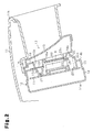
Fig. 2 is an enlarged cross-sectional view taken along a line 2-2 inFig. 1 , showing a state where the display device is incorporated in a vehicle instrument panel; -
Fig. 3 is an enlarged partial cross-sectional view showing a part inFig. 2 ; and -
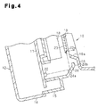
Fig. 4 is a partial cross-sectional view showing a modification. - A vehicle meter device according to one embodiment of the present invention will be described with reference to the drawings.
- As shown in
Figs. 1 and2 , ameter device 10 in this embodiment is installed in an opening 11a of avehicle instrument panel 11, and adisplay device 12 is incorporated thereinto. The meter device is located in the opening 11a below ahood portion 11 b of theinstrument panel 11, and afront plate 13 formed of a transparent plate is arranged at afront frame 16 of themeter device 10 so as to cover acolor filter 19 of thedisplay device 12. Thefront plate 13 is subjected to smoke processing for setting a predetermined transmittance (for example, 33%) with respect to the brightness of a luminous source. - The
display device 12 includes acase 15 configured of a horizontally long box-likerear case member 14a, the front of which is opened, and afront case member 14b assembled to the front opened portion of therear case member 14a. A plurality oflight guiding portions 15a are formed in a front upper portion of thefront case member 14b so as to arrange thelight guiding portions 15a at intervals in a horizontal direction when viewed from the front. Thefront frame 16 is attached to the front of thefront case member 14b. A horizontallylong display window 16a is formed in a front lower portion of thefront frame 16. Adisplay hole 16b corresponding to each of thelight guiding portions 15a of thefront case member 14b is formed in the front upper portion of thefront frame 16. - As shown in
Fig. 2 , acircuit board 17, which mounts control components and operating components for thedisplay device 12, is arranged in thecase 15. A light-emittingdisplay unit 18 formed of a VFD (Vacuum Fluorescent Display) is arranged at the front of thecircuit board 17 so as to correspond to thedisplay window 16a of thefront frame 16. As shown inFig. 1 , the light-emittingdisplay unit 18 is provided with a plurality of displays formed of light-emitting elements for displaying the vehicle driving state, and in this embodiment, avehicle speed display 18a, ashift position display 18b, afuel level display 18c and atime display 18d are provided. The color filter 19 (e.g. pale red) for converting light of the display elements of the light-emitting display unit 18 (e.g. green) into light of color with less stimulus (e.g. white) is arranged at the front of the light-emittingdisplay unit 18. Thecolor filter 19 is subjected to smoke processing for setting a predetermined transmittance (for example, about 25%) with respect to brightness of a luminous source. - As shown in
Fig. 2 , adisplay plate 20 is arranged between thelight guiding portions 15a of thefront case member 14b and thedisplay hole 16b of thefront frame 16. Thedisplay plate 20 is colored black except for display marks, which will be discussed below. As shown inFig. 1 , a plurality of translucent display marks for displaying the vehicle driving state, such as alamp illumination mark 20a, aseatbelt reminder mark 20b, aleft blinker mark 20c and aright blinker mark 20d, are assigned at positions corresponding to each of thelight guiding portions 15a of thedisplay plate 20. A plurality of display light-emittingelements 21 are arranged at the front of thecircuit board 17 so as to correspond to thelight guiding portions 15a of thefront case member 14b. The display light-emittingelements 21 emit light, thereby displaying the display marks 20a to 20d on thedisplay plate 20 in a standing out manner. The display marks 20a to 20d are invisible in the state where the display light-emittingelements 21 do not emit light. Thefront frame 16 is jet-black and thus, is almost invisible, and the boundary between thefront frame 16 and thedisplay plate 20 is also invisible. - As shown in
Figs. 2 and3 , in an outer lower portion of the light-emittingdisplay unit 18, a plurality of decorative (illumination) light-emittingelements 22 are horizontally arranged at the front of thecircuit board 17. Aninclined portion 23 is formed at a lower end of thecolor filter 19, and a light-dischargingsurface 23a for discharging light from the decorative light-emittingelements 22 is formed at the front of theinclined portion 23 so as extend in the horizontal direction. The light-dischargingsurface 23a is formed by roughening the front surface of theinclined portion 23, for example, by applying fine grain finishing. - An
inclined reflection portion 24 is formed at lower front end of thefront case member 14b so as to be located in a light path from the decorative light-emittingelements 22 to the light-dischargingsurface 23a. A reflectingsurface 24a for reflecting light from the decorative light-emittingelements 22 and allowing the light to reach the light-dischargingsurface 23a is formed in the inner surface of thereflection portion 24. The reflectingsurface 24a is formed by applying mirror-like finishing such as metal evaporation and metal plating to the inner surface of thereflection portion 24. Abarrier portion 24b protrudes from an upper end of thereflection portion 24, preventing excessive light from the decorative light-emittingelements 22 from leaking in the forward direction. - A
wall portion 25 protruding downward is provided at a lower end of thecolor filter 19 so as to be connected to theinclined portion 23. The existence of thewall portion 25 prevents light from the reflectingsurface 24a from leaking to the back surface of thecolor filter 19. - Next, operation of the vehicle meter device thus configured will be described.
- During driving of the vehicle, the driving state is displayed through light emission of the
displays 18a to 18d of the light-emittingdisplay unit 18 and light emission of the display marks 20a to 20d by the display light-emittingelements 21. In this case, display light of the light-emittingdisplay unit 18 is converted into light of color that has less visual stimulus but is highly visible through thecolor filter 19. In displaying the driving state, the decorative light-emittingelements 22 emit light, and the light is guided to the light-dischargingsurface 23a below thecolor filter 19 through the reflectingsurface 24a and then, the decorative light is discharged from the light-dischargingsurface 23a in the forward direction. Therefore, thedisplay device 12 can achieve an excellent decorative effect. - This embodiment achieves the following advantages.
- (1) In this embodiment, the light-discharging
surface 23a for discharging light from the decorative light-emittingelements 22 through the reflectingsurface 24a in the forward direction is formed at the lower end of thecolor filter 19 arranged at the light-emittingdisplay unit 18. For this reason, the decorative effect of thedisplay device 12 can be obtained by utilizing thecolor filter 19 for the light-emittingdisplay unit 18. Further, since the decorative light-emittingelements 22 can be used only for decorative illumination, not for display, a highly decorative effect can be obtained. - (2) In this embodiment, since the
barrier portion 24b of thereflection portion 24 prevents excessive light from the light-emittingdisplay unit 18 to leak in the forward direction, loss of the decorative effect can be prevented. - (3) In this embodiment, the reflecting
surface 24a is formed in the light path of the decorative light-emittingelements 22, and light from the decorative light-emittingelements 22 reaches the light-dischargingsurface 23a through the reflectingsurface 24a. For this reason, even when the decorative light-emittingelements 22 are located separately from the light-dischargingsurface 23a, light from the decorative light-emittingelements 22 can be guided to the light-dischargingsurface 23a through the reflectingsurface 24a. Accordingly, since the decorative light-emittingelements 22 can be incorporated at positions where they cannot be viewed from the outside and they can be easily mounted, excellent appearance can be obtained and the whole of the device can be reduced in size. - (4) In this embodiment, the light-discharging
surface 23a is formed by roughening theinclined portion 23 arranged at the end of thecolor filter 19. For this reason, the light-discharging surface can be formed without greatly changing the configuration of thecolor filter 19. - (5) In this embodiment, the reflecting
surface 24a is provided in a portion of thefront case member 14b of thedisplay device 12. For this reason, there is no need to arrange a dedicated reflection member having a reflecting surface in the light path of the decorative light-emittingelements 22, which contributes to a simple configuration. - (6) In this embodiment, the
color filter 19 is provided with thewall portion 25 for preventing light from the reflectingsurface 24a from leaking to the back surface of thecolor filter 19. For this reason, the light from the reflectingsurface 24a is prevented from leaking to the back surface of thecolor filter 19. This reduces the possibility that display unevenness due to shading or contrast occurs in display of the vehicle driving state by the light-emittingdisplay unit 18. - (7) In this embodiment, the
color filter 19 and thefront plate 13 are subjected to smoke processing. For this reason, undesirable parts of themeter device 10 in appearance, for example, structures such as printing pattern on the light-emittingdisplay unit 18 and fastening screws are hidden, and the vehicle driving state can be clearly displayed. In contrast, when thefront plate 13, which is not subjected to smoke processing, is used, the smoke opacity lacks and thus, the undesirable parts in appearance are visually recognized. This problem can be addressed only by increasing the smoke opacity of the color filter. However, in this case, the function of the color filter is degraded and the display brightness of each of thedisplays 18a to 18d in the light-emittingdisplay unit 18 cannot be ensured. This embodiment can avoid these problems. - The embodiment may be modified as follows.
- As shown in
Fig. 4 , the light-discharging surface 28a may be provided in a lower end surface of thecolor filter 19, and thewall portion 25 may be omitted. - Although the light-discharging
surface 23a is formed by roughening theinclined portion 23 of thecolor filter 19 in the embodiment, the light-dischargingsurface 23a may be formed by applying metal plating to theinclined portion 23 or adhering a reflective sheet to theinclined portion 23. - Although the reflecting
surface 24a is provided at a part of thefront case member 14b of thedisplay device 12 in this embodiment, the reflectingsurface 24a may be provided at a part of a vehicle component such as theinstrument panel 12. - Although the reflecting
surface 24a is provided at a part of thefront case 15 in this embodiment, the reflectingsurface 24a may be provided at the reflecting plate. - The
front plate 13 that is not subjected to smoke processing may be used in themeter device 10.
Claims (7)
- A display device comprising:a light-emitting display unit; anda color filter arranged at the front of the light-emitting display unit,the device being characterized in that a light-emitting element is provided in the outside of the light-emitting display unit, and a light-discharging surface for discharging light from the light-emitting element in a forward direction is formed at an end of the color filter.
- The display device according to claim 1, characterized in that a reflecting surface is provided in a light path of the light-emitting element, and light from the light-emitting element reaches the light-discharging surface through the reflecting surface.
- The display device according to claim 1 or 2, characterized in that the light-discharging surface is formed by roughening an end of the color filter.
- A meter device characterized in that the display device according to any one of claims 1 to 3 is incorporated in an opening of a vehicle instrument panel, wherein the light-emitting display unit displays the vehicle travelling state, and a transparent front plate is provided in the opening so as to cover the color filter.
- The meter device according to claim 4, characterized in that the reflecting surface is provided at a portion of the display device or a vehicle component.
- The meter device according to claim 4 or 5, characterized in that the color filter is provided with a wall portion for preventing light from the reflecting surface from leaking to a back surface of the color filter.
- The meter device according to any one of claims 4 to 6, characterized in that the color filter and the front plate are subjected to smoke processing.
Applications Claiming Priority (1)
| Application Number | Priority Date | Filing Date | Title |
|---|---|---|---|
| PCT/JP2009/070115 WO2011064887A1 (en) | 2009-11-30 | 2009-11-30 | Display device and meter device using same |
Publications (3)
| Publication Number | Publication Date |
|---|---|
| EP2509059A1 true EP2509059A1 (en) | 2012-10-10 |
| EP2509059A4 EP2509059A4 (en) | 2014-06-18 |
| EP2509059B1 EP2509059B1 (en) | 2016-09-07 |
Family
ID=44066006
Family Applications (1)
| Application Number | Title | Priority Date | Filing Date |
|---|---|---|---|
| EP09851677.6A Not-in-force EP2509059B1 (en) | 2009-11-30 | 2009-11-30 | Display device and meter device using same |
Country Status (4)
| Country | Link |
|---|---|
| US (1) | US8783922B2 (en) |
| EP (1) | EP2509059B1 (en) |
| JP (1) | JP5352680B2 (en) |
| WO (1) | WO2011064887A1 (en) |
Families Citing this family (7)
| Publication number | Priority date | Publication date | Assignee | Title |
|---|---|---|---|---|
| CN104870233B (en) * | 2012-11-13 | 2018-06-08 | 江森自控科技公司 | Illuminated vehicle interior components |
| CN104755879A (en) * | 2012-11-21 | 2015-07-01 | 歌乐株式会社 | Information processing device and browser control method thereof |
| JP5983667B2 (en) * | 2013-04-11 | 2016-09-06 | 株式会社デンソー | Vehicle display device |
| JP6367608B2 (en) * | 2014-05-19 | 2018-08-01 | 矢崎総業株式会社 | Vehicle display device |
| DE102014216208B4 (en) * | 2014-08-14 | 2026-02-19 | Robert Bosch Gmbh | Method and device for determining the reaction time of a vehicle driver |
| JP2019025947A (en) * | 2017-07-25 | 2019-02-21 | 株式会社デンソー | Display device for vehicle |
| CN114126922B (en) | 2018-11-23 | 2024-01-05 | 上海延锋金桥汽车饰件系统有限公司 | vehicle interior parts |
Family Cites Families (21)
| Publication number | Priority date | Publication date | Assignee | Title |
|---|---|---|---|---|
| JPS6071261U (en) | 1983-10-24 | 1985-05-20 | 鶴田 正克 | Golf practice device with bell |
| DE3704574C2 (en) | 1986-02-17 | 1994-06-09 | Yazaki Corp | Dial for a measuring instrument |
| JPS63197734U (en) | 1987-06-11 | 1988-12-20 | ||
| JPH0438381Y2 (en) | 1987-09-01 | 1992-09-08 | ||
| JP2601564Y2 (en) * | 1993-03-19 | 1999-11-22 | 矢崎総業株式会社 | Vehicle instrument |
| JP2918014B2 (en) | 1993-06-22 | 1999-07-12 | 矢崎総業株式会社 | Instrument lighting structure |
| JP2830900B2 (en) | 1994-05-13 | 1998-12-02 | 矢崎総業株式会社 | Display device for vehicles |
| JP2000016118A (en) | 1998-06-30 | 2000-01-18 | Nippon Seiki Co Ltd | Meter device |
| JP3610792B2 (en) | 1998-11-20 | 2005-01-19 | 日産自動車株式会社 | Vehicle engine start control device |
| JP3747452B2 (en) | 2000-03-31 | 2006-02-22 | 日本精機株式会社 | Meter device |
| JP2002351358A (en) | 2001-05-23 | 2002-12-06 | Nippon Seiki Co Ltd | Display device |
| JP2003057629A (en) | 2001-08-10 | 2003-02-26 | Alpine Electronics Inc | Display panel device |
| JP4438322B2 (en) * | 2003-06-04 | 2010-03-24 | ソニー株式会社 | Panel display |
| JP2005084153A (en) | 2003-09-05 | 2005-03-31 | Denso:Kk | Display device |
| JP2005233276A (en) | 2004-02-18 | 2005-09-02 | Ntn Corp | Traction drive type continuously variable transmission |
| JP2006059565A (en) | 2004-08-17 | 2006-03-02 | Denso Corp | Lighting structure |
| US7780304B2 (en) * | 2004-09-03 | 2010-08-24 | Continental Automotive Systems Us, Inc. | Smoked lens for vehicle |
| JP2006145334A (en) | 2004-11-18 | 2006-06-08 | Calsonic Kansei Corp | Instrument for vehicle |
| JP2006350147A (en) | 2005-06-20 | 2006-12-28 | Nippon Seiki Co Ltd | Display device |
| US7494256B1 (en) * | 2006-04-05 | 2009-02-24 | Yazaki North America, Inc. | Illuminated instrument cluster with perceived 3-D display segments |
| JP2008261664A (en) | 2007-04-10 | 2008-10-30 | Calsonic Kansei Corp | Meter device |
-
2009
- 2009-11-30 JP JP2011543062A patent/JP5352680B2/en active Active
- 2009-11-30 EP EP09851677.6A patent/EP2509059B1/en not_active Not-in-force
- 2009-11-30 WO PCT/JP2009/070115 patent/WO2011064887A1/en not_active Ceased
- 2009-11-30 US US13/512,284 patent/US8783922B2/en active Active
Also Published As
| Publication number | Publication date |
|---|---|
| US8783922B2 (en) | 2014-07-22 |
| JP5352680B2 (en) | 2013-11-27 |
| EP2509059A4 (en) | 2014-06-18 |
| US20120262901A1 (en) | 2012-10-18 |
| WO2011064887A1 (en) | 2011-06-03 |
| EP2509059B1 (en) | 2016-09-07 |
| JPWO2011064887A1 (en) | 2013-04-11 |
Similar Documents
| Publication | Publication Date | Title |
|---|---|---|
| EP2509059B1 (en) | Display device and meter device using same | |
| US6100943A (en) | Vehicular display device for directly and indirectly displaying information | |
| US6379015B2 (en) | Indicating instrument with an illuminated pointer disposed behind the dial | |
| US9316511B2 (en) | Three-dimensional design section structure of meter for automobile | |
| US6727962B2 (en) | Combination instrument for a motor vehicle | |
| CN107710314A (en) | Display device | |
| JP4622751B2 (en) | Vehicle display device | |
| US7278748B2 (en) | Display apparatus | |
| JP4802980B2 (en) | Display device | |
| JP2018080954A (en) | Display device | |
| JP4186910B2 (en) | Display device | |
| JP2009251419A (en) | Display apparatus | |
| JP2005067443A (en) | Vehicle display device | |
| JP2005091218A (en) | Vehicle display device | |
| JP4514569B2 (en) | Display device | |
| JP4858228B2 (en) | Pointer instrument | |
| JP4600234B2 (en) | Vehicle instrument | |
| JP2004226364A (en) | Display device for vehicles | |
| JP5767902B2 (en) | Vehicle instrument | |
| JP2024021153A (en) | display device | |
| KR20090063584A (en) | Pointer on the instrument cluster | |
| JP2005309157A (en) | Display device | |
| JP2007101358A (en) | Vehicle instrument | |
| US20140116321A1 (en) | Meter with pointer | |
| KR101073397B1 (en) | Unification display window having indirectness light emitted diode illuminator |
Legal Events
| Date | Code | Title | Description |
|---|---|---|---|
| PUAI | Public reference made under article 153(3) epc to a published international application that has entered the european phase |
Free format text: ORIGINAL CODE: 0009012 |
|
| 17P | Request for examination filed |
Effective date: 20120424 |
|
| AK | Designated contracting states |
Kind code of ref document: A1 Designated state(s): AT BE BG CH CY CZ DE DK EE ES FI FR GB GR HR HU IE IS IT LI LT LU LV MC MK MT NL NO PL PT RO SE SI SK SM TR |
|
| RAP1 | Party data changed (applicant data changed or rights of an application transferred) |
Owner name: TOYOTA SHATAI KABUSHIKI KAISHA Owner name: YAZAKI CORPORATION Owner name: TOYOTA JIDOSHA KABUSHIKI KAISHA |
|
| DAX | Request for extension of the european patent (deleted) | ||
| A4 | Supplementary search report drawn up and despatched |
Effective date: 20140521 |
|
| RIC1 | Information provided on ipc code assigned before grant |
Ipc: G09F 13/20 20060101ALI20140515BHEP Ipc: B60K 35/00 20060101AFI20140515BHEP Ipc: B60Q 3/04 20060101ALI20140515BHEP Ipc: G01D 11/28 20060101ALI20140515BHEP Ipc: G01D 11/24 20060101ALI20140515BHEP Ipc: G09F 13/02 20060101ALI20140515BHEP Ipc: G09F 9/00 20060101ALI20140515BHEP Ipc: G09F 13/04 20060101ALI20140515BHEP Ipc: B60K 37/02 20060101ALI20140515BHEP |
|
| REG | Reference to a national code |
Ref country code: DE Ref legal event code: R079 Ref document number: 602009041064 Country of ref document: DE Free format text: PREVIOUS MAIN CLASS: G09F0009000000 Ipc: B60K0035000000 |
|
| RIC1 | Information provided on ipc code assigned before grant |
Ipc: B60K 35/00 20060101AFI20160415BHEP Ipc: G01D 11/28 20060101ALI20160415BHEP Ipc: G09F 13/20 20060101ALI20160415BHEP Ipc: G01D 11/24 20060101ALI20160415BHEP Ipc: B60Q 3/04 20060101ALI20160415BHEP Ipc: B60K 37/02 20060101ALI20160415BHEP Ipc: G09F 9/00 20060101ALI20160415BHEP Ipc: G09F 13/02 20060101ALI20160415BHEP Ipc: G09F 13/04 20060101ALI20160415BHEP |
|
| GRAP | Despatch of communication of intention to grant a patent |
Free format text: ORIGINAL CODE: EPIDOSNIGR1 |
|
| INTG | Intention to grant announced |
Effective date: 20160607 |
|
| RAP1 | Party data changed (applicant data changed or rights of an application transferred) |
Owner name: TOYOTA SHATAI KABUSHIKI KAISHA Owner name: YAZAKI CORPORATION Owner name: TOYOTA JIDOSHA KABUSHIKI KAISHA |
|
| RIN1 | Information on inventor provided before grant (corrected) |
Inventor name: ICHIHARA, HIROAKI Inventor name: AIKAWA, KOJI Inventor name: TATSUTA, YOSHIFUMI Inventor name: SHIMADA, TAKAHIRO Inventor name: NOMURA, KOJI Inventor name: KINOSHITA, MASAHARU Inventor name: MINAKATA, MASATO |
|
| GRAS | Grant fee paid |
Free format text: ORIGINAL CODE: EPIDOSNIGR3 |
|
| GRAA | (expected) grant |
Free format text: ORIGINAL CODE: 0009210 |
|
| AK | Designated contracting states |
Kind code of ref document: B1 Designated state(s): AT BE BG CH CY CZ DE DK EE ES FI FR GB GR HR HU IE IS IT LI LT LU LV MC MK MT NL NO PL PT RO SE SI SK SM TR |
|
| REG | Reference to a national code |
Ref country code: GB Ref legal event code: FG4D |
|
| REG | Reference to a national code |
Ref country code: CH Ref legal event code: EP |
|
| REG | Reference to a national code |
Ref country code: IE Ref legal event code: FG4D |
|
| REG | Reference to a national code |
Ref country code: AT Ref legal event code: REF Ref document number: 826513 Country of ref document: AT Kind code of ref document: T Effective date: 20161015 |
|
| REG | Reference to a national code |
Ref country code: DE Ref legal event code: R096 Ref document number: 602009041064 Country of ref document: DE |
|
| REG | Reference to a national code |
Ref country code: FR Ref legal event code: PLFP Year of fee payment: 8 |
|
| REG | Reference to a national code |
Ref country code: LT Ref legal event code: MG4D |
|
| REG | Reference to a national code |
Ref country code: NL Ref legal event code: MP Effective date: 20160907 |
|
| PG25 | Lapsed in a contracting state [announced via postgrant information from national office to epo] |
Ref country code: NO Free format text: LAPSE BECAUSE OF FAILURE TO SUBMIT A TRANSLATION OF THE DESCRIPTION OR TO PAY THE FEE WITHIN THE PRESCRIBED TIME-LIMIT Effective date: 20161207 Ref country code: HR Free format text: LAPSE BECAUSE OF FAILURE TO SUBMIT A TRANSLATION OF THE DESCRIPTION OR TO PAY THE FEE WITHIN THE PRESCRIBED TIME-LIMIT Effective date: 20160907 Ref country code: LT Free format text: LAPSE BECAUSE OF FAILURE TO SUBMIT A TRANSLATION OF THE DESCRIPTION OR TO PAY THE FEE WITHIN THE PRESCRIBED TIME-LIMIT Effective date: 20160907 Ref country code: FI Free format text: LAPSE BECAUSE OF FAILURE TO SUBMIT A TRANSLATION OF THE DESCRIPTION OR TO PAY THE FEE WITHIN THE PRESCRIBED TIME-LIMIT Effective date: 20160907 |
|
| REG | Reference to a national code |
Ref country code: AT Ref legal event code: MK05 Ref document number: 826513 Country of ref document: AT Kind code of ref document: T Effective date: 20160907 |
|
| PG25 | Lapsed in a contracting state [announced via postgrant information from national office to epo] |
Ref country code: ES Free format text: LAPSE BECAUSE OF FAILURE TO SUBMIT A TRANSLATION OF THE DESCRIPTION OR TO PAY THE FEE WITHIN THE PRESCRIBED TIME-LIMIT Effective date: 20160907 Ref country code: BE Free format text: LAPSE BECAUSE OF NON-PAYMENT OF DUE FEES Effective date: 20161130 Ref country code: GR Free format text: LAPSE BECAUSE OF FAILURE TO SUBMIT A TRANSLATION OF THE DESCRIPTION OR TO PAY THE FEE WITHIN THE PRESCRIBED TIME-LIMIT Effective date: 20161208 Ref country code: SE Free format text: LAPSE BECAUSE OF FAILURE TO SUBMIT A TRANSLATION OF THE DESCRIPTION OR TO PAY THE FEE WITHIN THE PRESCRIBED TIME-LIMIT Effective date: 20160907 Ref country code: NL Free format text: LAPSE BECAUSE OF FAILURE TO SUBMIT A TRANSLATION OF THE DESCRIPTION OR TO PAY THE FEE WITHIN THE PRESCRIBED TIME-LIMIT Effective date: 20160907 Ref country code: LV Free format text: LAPSE BECAUSE OF FAILURE TO SUBMIT A TRANSLATION OF THE DESCRIPTION OR TO PAY THE FEE WITHIN THE PRESCRIBED TIME-LIMIT Effective date: 20160907 |
|
| PG25 | Lapsed in a contracting state [announced via postgrant information from national office to epo] |
Ref country code: RO Free format text: LAPSE BECAUSE OF FAILURE TO SUBMIT A TRANSLATION OF THE DESCRIPTION OR TO PAY THE FEE WITHIN THE PRESCRIBED TIME-LIMIT Effective date: 20160907 Ref country code: EE Free format text: LAPSE BECAUSE OF FAILURE TO SUBMIT A TRANSLATION OF THE DESCRIPTION OR TO PAY THE FEE WITHIN THE PRESCRIBED TIME-LIMIT Effective date: 20160907 |
|
| PG25 | Lapsed in a contracting state [announced via postgrant information from national office to epo] |
Ref country code: BE Free format text: LAPSE BECAUSE OF FAILURE TO SUBMIT A TRANSLATION OF THE DESCRIPTION OR TO PAY THE FEE WITHIN THE PRESCRIBED TIME-LIMIT Effective date: 20160907 Ref country code: AT Free format text: LAPSE BECAUSE OF FAILURE TO SUBMIT A TRANSLATION OF THE DESCRIPTION OR TO PAY THE FEE WITHIN THE PRESCRIBED TIME-LIMIT Effective date: 20160907 Ref country code: CZ Free format text: LAPSE BECAUSE OF FAILURE TO SUBMIT A TRANSLATION OF THE DESCRIPTION OR TO PAY THE FEE WITHIN THE PRESCRIBED TIME-LIMIT Effective date: 20160907 Ref country code: IS Free format text: LAPSE BECAUSE OF FAILURE TO SUBMIT A TRANSLATION OF THE DESCRIPTION OR TO PAY THE FEE WITHIN THE PRESCRIBED TIME-LIMIT Effective date: 20170107 Ref country code: SM Free format text: LAPSE BECAUSE OF FAILURE TO SUBMIT A TRANSLATION OF THE DESCRIPTION OR TO PAY THE FEE WITHIN THE PRESCRIBED TIME-LIMIT Effective date: 20160907 Ref country code: PT Free format text: LAPSE BECAUSE OF FAILURE TO SUBMIT A TRANSLATION OF THE DESCRIPTION OR TO PAY THE FEE WITHIN THE PRESCRIBED TIME-LIMIT Effective date: 20170109 Ref country code: PL Free format text: LAPSE BECAUSE OF FAILURE TO SUBMIT A TRANSLATION OF THE DESCRIPTION OR TO PAY THE FEE WITHIN THE PRESCRIBED TIME-LIMIT Effective date: 20160907 Ref country code: SK Free format text: LAPSE BECAUSE OF FAILURE TO SUBMIT A TRANSLATION OF THE DESCRIPTION OR TO PAY THE FEE WITHIN THE PRESCRIBED TIME-LIMIT Effective date: 20160907 Ref country code: BG Free format text: LAPSE BECAUSE OF FAILURE TO SUBMIT A TRANSLATION OF THE DESCRIPTION OR TO PAY THE FEE WITHIN THE PRESCRIBED TIME-LIMIT Effective date: 20161207 |
|
| REG | Reference to a national code |
Ref country code: DE Ref legal event code: R097 Ref document number: 602009041064 Country of ref document: DE |
|
| PG25 | Lapsed in a contracting state [announced via postgrant information from national office to epo] |
Ref country code: IT Free format text: LAPSE BECAUSE OF FAILURE TO SUBMIT A TRANSLATION OF THE DESCRIPTION OR TO PAY THE FEE WITHIN THE PRESCRIBED TIME-LIMIT Effective date: 20160907 |
|
| REG | Reference to a national code |
Ref country code: CH Ref legal event code: PL |
|
| PLBE | No opposition filed within time limit |
Free format text: ORIGINAL CODE: 0009261 |
|
| STAA | Information on the status of an ep patent application or granted ep patent |
Free format text: STATUS: NO OPPOSITION FILED WITHIN TIME LIMIT |
|
| PG25 | Lapsed in a contracting state [announced via postgrant information from national office to epo] |
Ref country code: LI Free format text: LAPSE BECAUSE OF NON-PAYMENT OF DUE FEES Effective date: 20161130 Ref country code: DK Free format text: LAPSE BECAUSE OF FAILURE TO SUBMIT A TRANSLATION OF THE DESCRIPTION OR TO PAY THE FEE WITHIN THE PRESCRIBED TIME-LIMIT Effective date: 20160907 Ref country code: CH Free format text: LAPSE BECAUSE OF NON-PAYMENT OF DUE FEES Effective date: 20161130 |
|
| 26N | No opposition filed |
Effective date: 20170608 |
|
| REG | Reference to a national code |
Ref country code: IE Ref legal event code: MM4A |
|
| PG25 | Lapsed in a contracting state [announced via postgrant information from national office to epo] |
Ref country code: SI Free format text: LAPSE BECAUSE OF FAILURE TO SUBMIT A TRANSLATION OF THE DESCRIPTION OR TO PAY THE FEE WITHIN THE PRESCRIBED TIME-LIMIT Effective date: 20160907 |
|
| PG25 | Lapsed in a contracting state [announced via postgrant information from national office to epo] |
Ref country code: LU Free format text: LAPSE BECAUSE OF NON-PAYMENT OF DUE FEES Effective date: 20161130 |
|
| REG | Reference to a national code |
Ref country code: FR Ref legal event code: PLFP Year of fee payment: 9 |
|
| PG25 | Lapsed in a contracting state [announced via postgrant information from national office to epo] |
Ref country code: IE Free format text: LAPSE BECAUSE OF NON-PAYMENT OF DUE FEES Effective date: 20161130 |
|
| PG25 | Lapsed in a contracting state [announced via postgrant information from national office to epo] |
Ref country code: CY Free format text: LAPSE BECAUSE OF FAILURE TO SUBMIT A TRANSLATION OF THE DESCRIPTION OR TO PAY THE FEE WITHIN THE PRESCRIBED TIME-LIMIT Effective date: 20160907 Ref country code: HU Free format text: LAPSE BECAUSE OF FAILURE TO SUBMIT A TRANSLATION OF THE DESCRIPTION OR TO PAY THE FEE WITHIN THE PRESCRIBED TIME-LIMIT; INVALID AB INITIO Effective date: 20091130 |
|
| PG25 | Lapsed in a contracting state [announced via postgrant information from national office to epo] |
Ref country code: MK Free format text: LAPSE BECAUSE OF FAILURE TO SUBMIT A TRANSLATION OF THE DESCRIPTION OR TO PAY THE FEE WITHIN THE PRESCRIBED TIME-LIMIT Effective date: 20160907 Ref country code: MC Free format text: LAPSE BECAUSE OF FAILURE TO SUBMIT A TRANSLATION OF THE DESCRIPTION OR TO PAY THE FEE WITHIN THE PRESCRIBED TIME-LIMIT Effective date: 20160907 Ref country code: TR Free format text: LAPSE BECAUSE OF FAILURE TO SUBMIT A TRANSLATION OF THE DESCRIPTION OR TO PAY THE FEE WITHIN THE PRESCRIBED TIME-LIMIT Effective date: 20160907 |
|
| PG25 | Lapsed in a contracting state [announced via postgrant information from national office to epo] |
Ref country code: MT Free format text: LAPSE BECAUSE OF NON-PAYMENT OF DUE FEES Effective date: 20161130 |
|
| REG | Reference to a national code |
Ref country code: FR Ref legal event code: PLFP Year of fee payment: 10 |
|
| PGFP | Annual fee paid to national office [announced via postgrant information from national office to epo] |
Ref country code: FR Payment date: 20221010 Year of fee payment: 14 |
|
| PGFP | Annual fee paid to national office [announced via postgrant information from national office to epo] |
Ref country code: GB Payment date: 20221006 Year of fee payment: 14 Ref country code: DE Payment date: 20221004 Year of fee payment: 14 |
|
| REG | Reference to a national code |
Ref country code: DE Ref legal event code: R119 Ref document number: 602009041064 Country of ref document: DE |
|
| GBPC | Gb: european patent ceased through non-payment of renewal fee |
Effective date: 20231130 |
|
| PG25 | Lapsed in a contracting state [announced via postgrant information from national office to epo] |
Ref country code: DE Free format text: LAPSE BECAUSE OF NON-PAYMENT OF DUE FEES Effective date: 20240601 |
|
| PG25 | Lapsed in a contracting state [announced via postgrant information from national office to epo] |
Ref country code: GB Free format text: LAPSE BECAUSE OF NON-PAYMENT OF DUE FEES Effective date: 20231130 |
|
| PG25 | Lapsed in a contracting state [announced via postgrant information from national office to epo] |
Ref country code: FR Free format text: LAPSE BECAUSE OF NON-PAYMENT OF DUE FEES Effective date: 20231130 |
|
| PG25 | Lapsed in a contracting state [announced via postgrant information from national office to epo] |
Ref country code: GB Free format text: LAPSE BECAUSE OF NON-PAYMENT OF DUE FEES Effective date: 20231130 Ref country code: FR Free format text: LAPSE BECAUSE OF NON-PAYMENT OF DUE FEES Effective date: 20231130 Ref country code: DE Free format text: LAPSE BECAUSE OF NON-PAYMENT OF DUE FEES Effective date: 20240601 |