EP2508945B1 - Direktionale Klangerfassung - Google Patents
Direktionale Klangerfassung Download PDFInfo
- Publication number
- EP2508945B1 EP2508945B1 EP11161466.5A EP11161466A EP2508945B1 EP 2508945 B1 EP2508945 B1 EP 2508945B1 EP 11161466 A EP11161466 A EP 11161466A EP 2508945 B1 EP2508945 B1 EP 2508945B1
- Authority
- EP
- European Patent Office
- Prior art keywords
- gaze direction
- sound recording
- user
- primary gaze
- sound
- Prior art date
- Legal status (The legal status is an assumption and is not a legal conclusion. Google has not performed a legal analysis and makes no representation as to the accuracy of the status listed.)
- Active
Links
- 230000003321 amplification Effects 0.000 claims description 28
- 238000003199 nucleic acid amplification method Methods 0.000 claims description 28
- 238000000034 method Methods 0.000 claims description 24
- 210000003128 head Anatomy 0.000 claims description 10
- 230000033001 locomotion Effects 0.000 description 6
- 230000002238 attenuated effect Effects 0.000 description 5
- 230000008901 benefit Effects 0.000 description 3
- 230000000694 effects Effects 0.000 description 3
- 230000001419 dependent effect Effects 0.000 description 1
- 238000010586 diagram Methods 0.000 description 1
- 230000006870 function Effects 0.000 description 1
- 230000004886 head movement Effects 0.000 description 1
- 238000002044 microwave spectrum Methods 0.000 description 1
- 238000001228 spectrum Methods 0.000 description 1
- 238000002604 ultrasonography Methods 0.000 description 1
Images


Classifications
-
- G—PHYSICS
- G03—PHOTOGRAPHY; CINEMATOGRAPHY; ANALOGOUS TECHNIQUES USING WAVES OTHER THAN OPTICAL WAVES; ELECTROGRAPHY; HOLOGRAPHY
- G03B—APPARATUS OR ARRANGEMENTS FOR TAKING PHOTOGRAPHS OR FOR PROJECTING OR VIEWING THEM; APPARATUS OR ARRANGEMENTS EMPLOYING ANALOGOUS TECHNIQUES USING WAVES OTHER THAN OPTICAL WAVES; ACCESSORIES THEREFOR
- G03B31/00—Associated working of cameras or projectors with sound-recording or sound-reproducing means
Definitions
- the present invention relates to the field of directional sound capturing and more particularly to a device and a method for capturing sound from a certain direction or certain directions. Particular aspects of the invention relate to directional sound capturing in a portable device.
- sound can be captured by means of microphones of various kinds. It is also known that sound from a particular direction can be captured by means of directional microphones with the effect that sound from a particular direction is amplified compared to sounds from other directions, and/or that sounds from other directions are attenuated compared to the sound from the particular direction.
- directional microphones will normally capture sound in a particular fixed direction. This direction may not be the direction of interest to a user of the directional microphone, or the user of the apparatus comprising the directional microphone.
- a directional microphone may only capture sound in a fixed direction
- the direction into which the directional microphone is currently directed may still not be the direction of interest to a user of the directional microphone. This is particularly so if the direction of interest is frequently changed, which e.g. may be the case if the user is interested in capture sound from a moving object such as a moving person or similar.
- the problem that the direction of interest is frequently changed may e.g. be solved by attaching the directional microphone to the head of the user, such that the user may turn his head in the direction of interest with the effect that the directional microphone will capture sounds in that direction.
- the problem that the direction of interest is frequently changed may also be solved by specifying a direction which is indicated using user's hands and body (see e.g. JP2010122369A ), a user's gaze (see e.g. WO2010149823A1 ), or by combination of audio and video of the user (see e.g. US2006075422A1 ).
- present invention is directed to solving the problem of providing an improved scheme for detecting sound from a certain direction or from certain directions.
- the sound recording arrangement 10 may be any electronic unit, e.g. a hearing aid arrangement or similar or a head set for professional use or for use during gaming activities or any other suitable sound recording and sound reproducing arrangement or similar.
- the sound recording arrangement 10 comprises a sound recording unit 12 capable of operatively capturing sounds arriving at the sound recording unit 12 from objects in the field of view of a user 20 of the sound recording arrangement 10, and a first image recording unit 14a configured to operatively record a first set of images of the head and/or the eyes of the user 20, and a control unit 18 that is configured to operatively determine a primary gaze direction 22 and/or 24 of the user 20 based on the first set of images, and that is further configured to operatively amplify sounds arriving in the primary gaze direction 22 and/or 24 compared to sounds arriving from other directions. This may e.g. be accomplished by amplifying sounds in the gaze direction, while sounds from other directions may be recorded without amplification. Alternatively, this may e.g.
- sounds in the gaze direction may be accomplished by amplifying sounds in the gaze direction, while sounds from other directions may be attenuated.
- this may e.g. be accomplished by recording sounds in the gaze direction without amplification while sounds from other directions may be attenuated, which in fact means that sounds in the gaze direction are amplified compared to other sounds.
- sounds in the gaze direction and the other sounds are mixed, while the sounds in the gaze directions are amplified compared to the other sounds.
- the level of amplification of the sounds in the gaze direction may be adjustable and/or set to a predetermined level, e.g. depending on the user's which and/or depending on the working environment wherein the sound recording arrangement 10 is to be used.
- the sound recording unit 12 comprises a cluster of sound recording devices, e.g. a first sound recording device 12a and a second sound recording device 12b, e.g. arranged to operatively receive sounds omnidirectional, or within a circle sector of less than 45°, or less than 90°, or less than 135°, or less than 180°, or less than 225°, or less than 270°, or less than 315°.
- a person skilled in the art realizes that the direction from which sounds are arriving at the sound recording unit 12 can be determined by using the first and the second sound recording devices 12a, 12b, e.g. by comparing the timing of the sound arriving at the first sound recording device 12a and the second sound recording device 12b. This may e.g.
- a typical phased array antenna operates in the microwave spectrum
- the sound recording unit 12 and the two sound recording devices 12a, 12b operate in the audible spectrum.
- the sound recording arrangement 10 will be able to amplify sounds arriving in one angular dimension only, e.g. in azimuth (i.e. the horizontal direction) or in elevation (i.e. the vertical) direction) based on sounds recorded by the two sound recording devices 12a and 12b.
- a third sound recording device 12c is added then the sound recording arrangement 10 will be able to amplify sounds arriving in two angular dimensions, e.g. in an azimuth (i.e. horizontal) direction and in an elevation (i.e.
- the three sound recording devices 12a, 12b and 12c are arranged in a non-linear fashion, e.g. arranged in a triangle pattern or according to any other suitable polygonal pattern.
- the sound recording unit 12 may have one, two, three or more sound recording devices. Two or more sound recording devices may e.g. be arranged in a linear fashion and/or in a polygonal fashion or similar, e.g. in a two or three dimensional array or similar.
- the first image recording unit 14a comprises one or more camera arrangements or similar that are configured to operatively record images of the head and/or the eyes of a user 20 of the sound recording arrangement.
- One camera arrangement may e.g. record one eye and another camera arrangement may record the other eye of the user 20.
- the first image recording unit 14a may e.g. comprise one or more still cameras, e.g. a digital still camera, preferably configured to record a number of consecutive by separate images of the user 20.
- the first image recording unit 14a may e.g. comprise one or more motion picture cameras, e.g. a digital video camera, which is configured to continuously record the user's motions.
- the sound recording arrangement 10 may also comprise a second image recording unit 14b configured to operatively record images of the field of view of the user 20 of the sound recording arrangement 10.
- the field of view of the user 20 corresponds to the whole or at least a part of the view of the surroundings that a user 20 can see while using the sound recording arrangement 10.
- the second image recording unit 14b is a camera arrangement or similar configured to operatively record images of the field of view.
- the second image recording unit 14b may e.g. be a still camera, e.g. a digital still camera, which is configured to record a number of consecutive by separate images of the field of view.
- the second image recording unit 14b may e.g. be a motion picture camera, e.g. a digital video camera, which is configured to continuously record the field of view.
- the sound recording arrangement 10 may also comprise a sound producing unit 19.
- the sound producing unit 19 is configured to operatively provide the user 20 of the sound recording arrangement 10 with sound captured by the sound recording unit 12, wherein the sound arriving at the sound recording unit 12 in the gaze direction 22 and/or 24 of the user 20 has been amplified, as will be elaborated in more detail later.
- the sound producing unit 19 may be any sound producing unit that is known by those skilled in the art to be suitable for the purposes described herein.
- the sound producing unit 19 may e.g. comprise a loudspeaker or similar configured to operatively produce sounds that can be heard by the user 20, e.g. sounds within the frequency range of 20-20 000 Hz.
- the sound recording arrangement 10 may comprise a distance measuring unit 16.
- the distance measuring unit 16 is configured to operatively obtain the distance to an object 40a and/or 40b in the gaze direction 22 and/or 24 respectively as will be elaborated in more detail later.
- the distance measuring unit 16 may be any distance measuring unit known by those skilled in the art to be suitable for the purposes described herein.
- the distance measuring unit 16 may e.g. comprise a sound measuring unit configured to measure distances by sending a sound pulse such as an ultrasound pulse or similar to a target and then measure the time it takes for the sound pulse to be reflected off the target and back to the unit in question.
- the distance measuring unit 16 may e.g.
- the distance measuring unit 16 may e.g. comprise an autofocus arrangement which directly or indirectly provides the distance to an object 40a and/or 40b in the gaze direction 22 and/or 24 respectively being in focus.
- the autofocus arrangement may e.g. be a part of the second image recording unit 14b configured to operatively record images of the field of view of the user 20 of the sound recording arrangement 10.
- the distance measuring unit 16 may e.g.
- the distance measuring unit 16 may then be configured to operatively estimate the distance to an object 40a and/or 40b at which the user 20 gazes by detecting the vergence of the eyes. It is well known to those skilled in the art that the vergence is the simultaneous movement of both eyes in opposite directions to obtain or maintain single binocular vision.
- the control unit 18 of the sound recording arrangement 10 may be implemented using hardware and/or software, e.g. in the form of special dedicated programs running on hardware in the form of an Application-Specific Integrated Circuit (ASIC) or similar.
- the control unit 18 is configured to control, monitor and/or communicate with the other parts and functions of the sound recording arrangement 10 so as to perform the actions or similar of the embodiments described herein.
- the control unit 18 may be configured to control, monitor and/or communicate with the sound recording unit 12, the first image recording unit 14a, and the second image recording unit 14b, and the distance measuring unit 16 and the sound producing unit 19.
- the sound recording unit 12 the first image recording unit 14a, the second image recording unit 14b, the distance measuring unit 16, and the sound producing unit 18 may be attached to, or arranged within the sound recording arrangement 10 and/or connected to the sound recording arrangement 10.
- the connection may e.g. be a wired or a wireless connection.
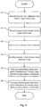
- FIG 3 is a schematic flowchart illustrating a method according to an embodiment of the present solution.
- the flowchart is discussed below with reference to the sound recording arrangement 10 described above with reference to Figure 1 and Figure 2 . However, the discussion applies mutatis mutandis to all sound recording arrangement with sound recording capabilities and image recording capabilities that are configured to operatively perform the actions according to embodiments of the present solution.
- a first action A1 it is preferred that sound arriving at the sound recording unit 12 from objects in the field of view of the user 20 of the sound recording arrangement 10 is recorded by, preferably by using the sound recording unit 12.
- the field of view of the user 20 may correspond to the view that the user 20 may look at or is currently looking at, in other words what the user 20 may see or what the user 20 currently sees.
- the objects may e.g. be a first person 40a and/or a second person 40b.
- the user 20 may e.g. talk and/or listen to the first person 40a and/or the second person 40b.
- a first set of images of the head and/or the eyes of the user 20 is recorded, preferably by using the first image recording unit 14a.
- a primary gaze direction of the user 20 is determined in part based on the first set of images recorded in the second action A2.
- Figure 1 schematically illustrates a first primary gaze direction 22, and a second primary gaze direction 24.
- the first primary gaze direction 22 the user gazes at a first object 40a
- the second primary gaze direction 24 the user 20 gazes at a second object 40b.
- a primary gaze direction is preferably determined when the user 20 repeatedly gazes in a particular direction in the field of view, and/or when the user 20 gaze in a direction in the field of view under a predetermined period. Glancing around in the field of view and/or shortly looking at an object in the field of view will not be enough to determine a primary gaze direction.
- the primary gaze direction is preferably determined in part by the control unit 18 operating on the first set of images by means of a suitable gaze tracking algorithm or similar.
- the gaze tracking algorithm may operate by only tracking the movements of one eye or both eyes of the user 20, e.g. in case the first set of images are recorded by a head mounted image recording unit 14a.
- the gaze tracking algorithm may operate by tracking the head movements and/or tracking the movements of one eye or both eyes of the user 20, e.g. in case the first set of images are recorded by a table mounted image recording unit 14a.
- the control unit 18 may start the third action by determine a secondary gaze direction of the user 20 based on the first set of images, where the sound recording arrangement 10 may comprise a second image recording unit 14b configured to operatively record a second set of images of an object 40a and/or 40b in the field of view of the user 20, which object 40a and/or 40b is located in the secondary gaze direction.
- the control unit 18 determines the primary gaze direction 22 and/or 24 of the user 20 based on the first set of images as indicated above, and based on a correlation of the secondary gaze direction and an object tracking of the object 40a and/or 40b in the second set of images.
- Object tracking using images or similar of an object is well known per se by those skilled in the art and it needs no further description.
- a fourth action A4 it is preferred that only sounds in the primary gaze direction 22 and/or 24 is amplified. It is preferred that the control unit 18 is configured to operatively amplify sounds in the primary gaze direction 22 and/or 24. Other sounds outside the primary gaze direction 22 and/or 24 may alternatively or additionally be attenuated, i.e. sounds from other directions than primary gaze direction 22 and/or 24 may be attenuated. When applicable, it is preferred that the control unit 18 is configured to operatively attenuate such other sounds.
- Figure 1 an exemplifying amplification in a first primary gaze direction 22, which amplification has been indicated by a conical shape 22a, and an exemplifying amplification in a second primary gaze direction 24, which amplification has been indicated by a conical shape 24a.
- the amplification may be compensated, e.g. for parallax differences, in case the sound recording unit 12 and the user 20 are located at different positions.
- the sound recording unit 12 may comprise a cluster of at least two sound recording devices 12a, 12b or at least three sound recording devices 12a, 12b, 12c.
- Each sound recording device 12a, 12b, 12c is capable of operatively capture sound from objects in the field of view of the user 20.
- sounds is only amplified in the primary gaze direction 22 and/or 24 in one angular dimension using said at least two sound recording devices 12a, 12b, or in two angular dimensions using said at least three sound recording devices 12a, 12b, 12c.
- the control unit 18 is configured to operatively amplify sounds in the primary gaze direction 22 and/or 24, and possibly to attenuate sounds outside the primary gaze direction 22 and/or 24.
- the sound recording unit 12 may comprise a distance measuring unit 16 configured to operatively obtain the distance to an object 40a and/or 40b in the primary gaze direction 22 and/or 24 respectively.
- the control unit 18 may be configured to operatively amplify sounds in the primary gaze direction 22 and/or 24 at the distance obtained by the distance measuring unit 16. For example, using the distance information it is possible to focus on sound coming far away or closer and not indiscriminately amplify sound in a certain direction.
- amplification of the sound received in the primary gaze direction 22 and/or 24 is reduced when the time during which the primary gaze direction 22 and/or 24 respectively remains the same drops below a predetermined threshold and/or the frequency at which the same primary gaze direction 22 and/or 24 is repeatedly determined drops below a predetermined threshold.
- the amplification in a primary gaze direction 22 and/or 24 may be reduced when no sound is recorded during a predetermined period in the primary gaze direction 22 and/or 24 respectively.
- the amplification may be gradually reduced.
- the control unit 18 may be configured to operatively reduce the amplification as indicated above.
- amplification of the sound received in the primary gaze direction 22 and/or 24 is raised when the time during which the primary gaze direction 22 and/or 24 respectively remains the same and/or the frequency at which the primary gaze direction 22 and/or 24 respectively is repeated is above a predetermined threshold.
- the amplification may be gradually raised.
- the amplification may be immediately raised when the current primary gaze direction is the same as a previously determined primary gaze direction.
- the control unit 18 may be configured to operatively raise the amplification as indicated above.
- sound in the primary gaze direction 22 and/or 24 may be amplified even if there is currently no sound arriving at the sound recording unit 12 in the primary gaze direction 22 and/or 24 respectively.
Landscapes
- Physics & Mathematics (AREA)
- General Physics & Mathematics (AREA)
- Electrophonic Musical Instruments (AREA)
- Stereophonic System (AREA)
Claims (18)
- Klangaufnahmevorrichtung (10), umfassend:eine Klangaufnahmeeinheit (12), die dazu imstande ist, betriebsmäßig Klang aufzunehmen, der an der Klangaufnahmeeinheit (12) von Objekten (40a; 40b) in einem Sichtfeld eines Benutzers (20) der Klangaufnahmevorrichtung (10) ankommt,eine erste Bildaufnahmeeinheit (14a),eine Steuereinheit (18),wobei:- die erste Bildaufnahmeeinheit (14a) dazu ausgelegt ist, betriebsmäßig einen ersten Satz von Bildern des Kopfes und/oder der Augen des Benutzers (20) aufzunehmen,- die Steuereinheit (18) dazu ausgelegt ist, betriebsmäßig eine primäre Blickrichtung (22; 24) des Benutzers (20) auf Grundlage des ersten Satzes von Bildern zu bestimmen, wobei die primäre Blickrichtung eine Richtung ist, in welche der Benutzer (20) wiederholt blickt oder in welche der Benutzer (29) für einen vorgegebenen Zeitraum blickt,- die Steuereinheit (18) ferner dazu ausgelegt ist, betriebsmäßig Klänge, die in der primären Blickrichtung (22; 24) ankommen, im Vergleich zu Klängen, die aus anderen Richtungen ankommen, zu verstärken,wobei die Klangaufnahmevorrichtung (10) dadurch gekennzeichnet ist, dass:- die Steuereinheit (18) ferner dazu ausgelegt ist, betriebsmäßig eine sekundäre Blickrichtung des Benutzers (20) auf Grundlage des ersten Satzes von Bildern zu bestimmen, wobei die sekundäre Blickrichtung eine Richtung im Sichtfeld des Benutzers (20) ist,- die Klangaufnahmevorrichtung (10) eine zweite Bildaufnahmeeinheit (14b) umfasst, die dazu ausgelegt ist, betriebsmäßig einen zweiten Satz von Bildern eines Objektes (40a; 40b) aufzunehmen, das sich in der sekundären Blickrichtung befindet,- die Steuereinheit (18) ferner dazu ausgelegt ist, betriebsmäßig das Objekt (40a; 40b) in dem zweiten Satz von Bildern zu verfolgen, und- die Steuereinheit (18) ferner dazu ausgelegt ist, betriebsmäßig die primäre Blickrichtung (22; 24) des Benutzers (20) auf Grundlage des ersten Satzes von Bildern und auf Grundlage einer Korrelation der sekundären Blickrichtung und der Verfolgung des Objektes (40a; 40b) in dem zweiten Satz von Bildern zu bestimmen.
- Klangaufnahmevorrichtung (10) nach Anspruch 1,
wobei:- die Klangaufnahmeeinheit (12) eine Gruppe aus mindestens zwei Klangaufnahmevorrichtungen (12a, 12b) oder mindestens drei Klangaufnahmevorrichtungen (12a, 12b, 12c) umfasst, die jeweils dazu imstande sind, betriebsmäßig Klänge von Objekten im Sichtfeld eines Benutzers (20) aufzunehmen, und- die Steuereinheit (18) dazu ausgelegt ist, betriebsmäßig Klänge in der primären Blickrichtung (22; 24) in einer Winkelabmessung unter Verwendung der mindestens zwei Klangaufnahmevorrichtungen (12a, 12b) oder in zwei Winkelabmessungen unter Verwendung der mindestens drei Klangaufnahmevorrichtungen (12a, 12b, 12c) zu verstärken. - Klangaufnahmevorrichtung (10) nach einem von Anspruch 1 oder 2, umfassend eine Abstandsmesseinheit (16), die dazu ausgelegt ist, betriebsmäßig den Abstand zu einem Objekt (40a, 40b) in der primären Blickrichtung (22; 24) zu erhalten,
wobei:
die Steuereinheit (18) dazu ausgelegt ist, betriebsmäßig Klänge in der primären Blickrichtung (22; 24) in einem von der Abstandsmesseinheit (16) erhaltenen Abstand zu verstärken. - Klangaufnahmevorrichtung (10) nach Anspruch 1,
wobei:
die Steuereinheit (18) dazu ausgelegt ist, betriebsmäßig die Verstärkung zu verringern, wenn die Zeit, während der die primäre Blickrichtung (22; 24) gleich bleibt, unter einen vorgegebenen Schwellenwert fällt und/oder die Frequenz, mit der die gleiche primäre Blickrichtung (22; 24) wiederholt bestimmt wird, unter einen vorgegebenen Schwellenwert fällt. - Klangaufnahmevorrichtung (10) nach Anspruch 1,
wobei:
die Steuereinheit (18) dazu ausgelegt ist, betriebsmäßig die Verstärkung zu verringern, wenn kein Klang in der primären Blickrichtung (22; 24) während eines vorgegebenen Zeitraums aufgenommen wird. - Klangaufnahmevorrichtung (10) nach einem von Anspruch 1, 4 oder 5,
wobei:
die Steuereinheit (18) dazu ausgelegt ist, betriebsmäßig die Verstärkung zu erhöhen, wenn die Zeit, während der die primäre Blickrichtung (22; 24) gleich bleibt, und/oder die Frequenz, mit der die primäre Blickrichtung (22; 24) wiederholt bestimmt wird, über einen vorgegebenen Schwellenwert steigt. - Klangaufnahmevorrichtung (10) nach Anspruch 6,
wobei:
die Steuereinheit (18) dazu ausgelegt ist, betriebsmäßig die Verstärkung allmählich zu erhöhen. - Klangaufnahmevorrichtung (10) nach Anspruch 7,
wobei:
die Steuereinheit (18) dazu ausgelegt ist, betriebsmäßig die Verstärkung sofort zu erhöhen, wenn die aktuelle primäre Blickrichtung (22; 24) gleich einer zuvor bestimmten primären Blickrichtung (22; 24) ist. - Klangaufnahmevorrichtung (10) nach Anspruch 1,
wobei:
die Steuereinheit (18) dazu ausgelegt ist, betriebsmäßig Klänge in der primären Blickrichtung (22; 24) zu verstärken, selbst wenn aktuell kein Klang an der Klangaufnahmeeinheit (12) in der primären Blickrichtung (22; 24) ankommt. - Verfahren in einer Klangaufnahmevorrichtung (10) zum Verstärken von Klängen in einer primären Blickrichtung eines Benutzers (20) der Klangaufnahmevorrichtung (10), wobei das Verfahren die folgenden Vorgänge umfasst:- Aufnehmen von Klängen, die an einer Klangaufnahmeeinheit (12) von Objekten (40a; 40b) im Sichtfeld des Benutzers (20) ankommen,- Aufnehmen, mit einer ersten Bildaufnahmeeinheit (14a), eines ersten Satzes von Bildern des Kopfes und/oder der Augen des Benutzers (20),- Bestimmen, mit einer Steuereinheit (18), einer primären Blickrichtung (22; 24) des Benutzers (20) auf Grundlage des ersten Satzes von Bildern, wobei die primäre Blickrichtung eine Richtung ist, in welche der Benutzer (20) wiederholt blickt oder in welche der Benutzer (20) während eines vorgegebenen Zeitraums blickt,- Verstärken, mit der Steuereinheit (18), von Klängen, die in der primären Blickrichtung (22; 24) ankommen, im Vergleich zu Klängen, die aus anderen Richtungen ankommen,wobei das Verfahren dadurch gekennzeichnet, dass es die folgenden Vorgänge umfasst:- Bestimmen einer sekundären Blickrichtung des Benutzers (20) auf Grundlage des ersten Satzes von Bildern, wobei die sekundäre Blickrichtung eine Richtung im Sichtfeld des Benutzers (20) ist,- Aufnehmen, mit einer zweiten Bildaufnahmeeinheit (14b), eines zweiten Satzes von Bildern eines Objektes (40a; 40b), das sich in der sekundären Blickrichtung befindet,- Verfolgen des Objektes (40a; 40b) in dem zweiten Satz von Bildern, und- ferner Bestimmen, mit der Steuereinheit (18), der primären Blickrichtung (22; 24) des Benutzers (20) auf Grundlage des ersten Satzes von Bildern und auf Grundlage einer Korrelation der sekundären Blickrichtung und der Verfolgung des Objektes (40a; 40b) in dem zweiten Satz von Bildern.
- Verfahren nach einem von Anspruch 10, wobei das Verfahren die folgenden Vorgänge umfasst:- Aufnehmen der Klänge von Objekten im Sichtfeld eines Benutzers (20) unter Verwendung von mindestens zwei Klangaufnahmevorrichtungen (12a, 12b) oder unter Verwendung von mindestens drei Klangaufnahmevorrichtungen (12a, 12b, 12c), und- Verstärken von Klängen in der primären Blickrichtung (22; 24) in einer Winkelabmessung auf Grundlage von Klängen, die von den mindestens zwei Klangaufnahmevorrichtungen (12a, 12b) aufgenommen werden, oder in zwei Winkelabmessungen auf Grundlage von Klängen, die von den mindestens drei Klangaufnahmevorrichtungen (12a, 12b, 12c) aufgenommen werden.
- Verfahren nach einem von Anspruch 10 oder 11, wobei das Verfahren die folgenden Vorgänge umfasst:- Erhalten des Abstands zu einem Objekt (40a, 40b) in der primären Blickrichtung (22; 24),- Verstärken von Klängen in der primären Blickrichtung (22; 24) in dem von der Abstandsmesseinheit (16) erhaltenen Abstand.
- Verfahren nach Anspruch 10,
wobei das Verfahren die folgenden Vorgänge umfasst:
Verringern der Verstärkung, wenn die Zeit, während der die primäre Blickrichtung (22; 24) gleich bleibt, unter einen vorgegebenen Schwellenwert fällt und/oder die Frequenz, mit der die gleiche primäre Blickrichtung (22; 24) wiederholt bestimmt wird, unter einen vorgegebenen Schwellenwert fällt. - Verfahren nach Anspruch 10,
wobei das Verfahren die folgenden Vorgänge umfasst:
Verringern der Verstärkung, wenn kein Klang in der primären Blickrichtung (22; 24) während eines vorgegebenen Zeitraums aufgenommen wird. - Verfahren nach einem von Anspruch 10, 13 oder 14,
wobei das Verfahren die folgenden Vorgänge umfasst:
Erhöhen der Verstärkung, wenn die Zeit, während der die primäre Blickrichtung (22; 24) gleich bleibt, und/oder die Frequenz, mit der die primäre Blickrichtung (22; 24) wiederholt bestimmt wird, über einen vorgegebenen Schwellenwert steigt. - Verfahren nach Anspruch 15,
wobei das Verfahren die folgenden Vorgänge umfasst:
allmähliches Erhöhen der Verstärkung. - Verfahren nach Anspruch 10,
wobei das Verfahren die folgenden Vorgänge umfasst:
Erhöhen der Verstärkung sofort, wenn die aktuelle primäre Blickrichtung (22; 24) gleich einer zuvor bestimmten primären Blickrichtung (22; 24) ist. - Verfahren nach Anspruch 10,
wobei das Verfahren die folgenden Vorgänge umfasst:
Verstärken von Klängen in der primären Blickrichtung (22; 24), selbst wenn aktuell kein Klang an der Klangaufnahmeeinheit (12) in der primären Blickrichtung (22; 24) ankommt.
Priority Applications (2)
| Application Number | Priority Date | Filing Date | Title |
|---|---|---|---|
| EP11161466.5A EP2508945B1 (de) | 2011-04-07 | 2011-04-07 | Direktionale Klangerfassung |
| US13/413,291 US9057943B2 (en) | 2011-04-07 | 2012-03-06 | Directional sound capturing |
Applications Claiming Priority (1)
| Application Number | Priority Date | Filing Date | Title |
|---|---|---|---|
| EP11161466.5A EP2508945B1 (de) | 2011-04-07 | 2011-04-07 | Direktionale Klangerfassung |
Publications (2)
| Publication Number | Publication Date |
|---|---|
| EP2508945A1 EP2508945A1 (de) | 2012-10-10 |
| EP2508945B1 true EP2508945B1 (de) | 2020-02-19 |
Family
ID=44144856
Family Applications (1)
| Application Number | Title | Priority Date | Filing Date |
|---|---|---|---|
| EP11161466.5A Active EP2508945B1 (de) | 2011-04-07 | 2011-04-07 | Direktionale Klangerfassung |
Country Status (2)
| Country | Link |
|---|---|
| US (1) | US9057943B2 (de) |
| EP (1) | EP2508945B1 (de) |
Families Citing this family (16)
| Publication number | Priority date | Publication date | Assignee | Title |
|---|---|---|---|---|
| DK1607840T3 (da) | 2004-06-18 | 2015-02-16 | Tobii Technology Ab | Øjenstyring af et computerapparat |
| US9554229B2 (en) * | 2011-10-31 | 2017-01-24 | Sony Corporation | Amplifying audio-visual data based on user's head orientation |
| US11714487B2 (en) | 2013-03-04 | 2023-08-01 | Tobii Ab | Gaze and smooth pursuit based continuous foveal adjustment |
| US10895908B2 (en) | 2013-03-04 | 2021-01-19 | Tobii Ab | Targeting saccade landing prediction using visual history |
| US9898081B2 (en) | 2013-03-04 | 2018-02-20 | Tobii Ab | Gaze and saccade based graphical manipulation |
| WO2014155153A1 (en) | 2013-03-27 | 2014-10-02 | Nokia Corporation | Image point of interest analyser with animation generator |
| EP2813175A3 (de) | 2013-06-14 | 2015-04-01 | Oticon A/s | Hörhilfevorrichtung mit Gehirn-Computer-Schnittstelle |
| US9143880B2 (en) * | 2013-08-23 | 2015-09-22 | Tobii Ab | Systems and methods for providing audio to a user based on gaze input |
| US10430150B2 (en) | 2013-08-23 | 2019-10-01 | Tobii Ab | Systems and methods for changing behavior of computer program elements based on gaze input |
| EP3138080B1 (de) * | 2014-06-03 | 2021-08-11 | Apple Inc. | Verfahren und system für die darstellung von digitalen informationen im zusammenhang mit einem realen objekt |
| US9898078B2 (en) | 2015-01-12 | 2018-02-20 | Dell Products, L.P. | Immersive environment correction display and method |
| US10021339B2 (en) * | 2015-12-01 | 2018-07-10 | Qualcomm Incorporated | Electronic device for generating video data |
| US9905244B2 (en) * | 2016-02-02 | 2018-02-27 | Ebay Inc. | Personalized, real-time audio processing |
| US10990171B2 (en) | 2018-12-27 | 2021-04-27 | Facebook Technologies, Llc | Audio indicators of user attention in AR/VR environment |
| US11022794B2 (en) * | 2018-12-27 | 2021-06-01 | Facebook Technologies, Llc | Visual indicators of user attention in AR/VR environment |
| US11375322B2 (en) * | 2020-02-28 | 2022-06-28 | Oticon A/S | Hearing aid determining turn-taking |
Family Cites Families (10)
| Publication number | Priority date | Publication date | Assignee | Title |
|---|---|---|---|---|
| US4021613A (en) * | 1975-06-09 | 1977-05-03 | Clive Kennedy | Audio information modifying apparatus |
| DE19547093A1 (de) * | 1995-12-16 | 1997-06-19 | Nokia Deutschland Gmbh | Schaltungsanordnung zur Verbesserung des Störabstandes |
| US8103033B2 (en) * | 2004-09-01 | 2012-01-24 | Bose Corporation | Audio system for portable device |
| KR100754385B1 (ko) * | 2004-09-30 | 2007-08-31 | 삼성전자주식회사 | 오디오/비디오 센서를 이용한 위치 파악, 추적 및 분리장치와 그 방법 |
| JP5050721B2 (ja) * | 2007-08-06 | 2012-10-17 | ソニー株式会社 | 情報処理装置、情報処理方法及びプログラム |
| US7747160B2 (en) * | 2008-01-04 | 2010-06-29 | Sony Ericsson Mobile Communications Ab | Intelligent red eye removal |
| JP5366043B2 (ja) * | 2008-11-18 | 2013-12-11 | 株式会社国際電気通信基礎技術研究所 | 音声記録再生装置 |
| US20120105486A1 (en) * | 2009-04-09 | 2012-05-03 | Dynavox Systems Llc | Calibration free, motion tolerent eye-gaze direction detector with contextually aware computer interaction and communication methods |
| EP2446642B1 (de) * | 2009-06-23 | 2017-04-12 | Nokia Technologies Oy | Verfahren und vorrichtung zum verarbeiten von audiosignalen |
| US8593375B2 (en) * | 2010-07-23 | 2013-11-26 | Gregory A Maltz | Eye gaze user interface and method |
-
2011
- 2011-04-07 EP EP11161466.5A patent/EP2508945B1/de active Active
-
2012
- 2012-03-06 US US13/413,291 patent/US9057943B2/en active Active
Non-Patent Citations (1)
| Title |
|---|
| None * |
Also Published As
| Publication number | Publication date |
|---|---|
| US20120257036A1 (en) | 2012-10-11 |
| US9057943B2 (en) | 2015-06-16 |
| EP2508945A1 (de) | 2012-10-10 |
Similar Documents
| Publication | Publication Date | Title |
|---|---|---|
| EP2508945B1 (de) | Direktionale Klangerfassung | |
| US10575117B2 (en) | Directional sound modification | |
| US9516241B2 (en) | Beamforming method and apparatus for sound signal | |
| US9622013B2 (en) | Directional sound modification | |
| US9900688B2 (en) | Beamforming audio with wearable device microphones | |
| EP2953348B1 (de) | Bestimmung, anzeige und einstellung des besten schallquellenplatzierungsbereichs in bezug auf ein mikrofon | |
| CN102577433B (zh) | 基于听众位置的音量调整 | |
| US9084038B2 (en) | Method of controlling audio recording and electronic device | |
| US20070025555A1 (en) | Method and apparatus for processing information, and computer product | |
| EP3342187B1 (de) | Unterdrückung von umgebungsgeräuschen | |
| DE10196882B3 (de) | Aufzeichnen von beweglichen Bildern | |
| JP2013048412A (ja) | オーディオエンハンス型装置 | |
| JP2004528766A (ja) | 音声/画像を用いて話者を感知し位置探しする方法及び装置 | |
| EP4358537A2 (de) | Direktionale klangmodifikation | |
| CN112866894A (zh) | 声场控制方法及装置、移动终端、存储介质 | |
| CN108063910A (zh) | 用于视频会议系统中的摄像机底座及其方法 | |
| EP3195618B1 (de) | Verfahren zum betrieb eines hörsystems sowie ein hörsystem | |
| US11902754B2 (en) | Audio processing method, apparatus, electronic device and storage medium | |
| JP6600186B2 (ja) | 情報処理装置、制御方法およびプログラム | |
| CN112188363B (zh) | 音频播放的控制方法、装置、电子设备和可读存储介质 | |
| US20240031527A1 (en) | Apparatus, systems, and methods for videoconferencing devices | |
| KR20240090752A (ko) | 시선-기반 오디오 빔포밍 | |
| CN117636928A (zh) | 一种拾音装置及相关音频增强方法 | |
| CN114174860A (zh) | 基于雷达的噪声过滤 | |
| KR20090017203A (ko) | 화자 위치 추적 방법 및 장치 |
Legal Events
| Date | Code | Title | Description |
|---|---|---|---|
| PUAI | Public reference made under article 153(3) epc to a published international application that has entered the european phase |
Free format text: ORIGINAL CODE: 0009012 |
|
| AK | Designated contracting states |
Kind code of ref document: A1 Designated state(s): AL AT BE BG CH CY CZ DE DK EE ES FI FR GB GR HR HU IE IS IT LI LT LU LV MC MK MT NL NO PL PT RO RS SE SI SK SM TR |
|
| AX | Request for extension of the european patent |
Extension state: BA ME |
|
| 17P | Request for examination filed |
Effective date: 20130318 |
|
| STAA | Information on the status of an ep patent application or granted ep patent |
Free format text: STATUS: EXAMINATION IS IN PROGRESS |
|
| 17Q | First examination report despatched |
Effective date: 20180612 |
|
| GRAP | Despatch of communication of intention to grant a patent |
Free format text: ORIGINAL CODE: EPIDOSNIGR1 |
|
| STAA | Information on the status of an ep patent application or granted ep patent |
Free format text: STATUS: GRANT OF PATENT IS INTENDED |
|
| INTG | Intention to grant announced |
Effective date: 20190731 |
|
| RIN1 | Information on inventor provided before grant (corrected) |
Inventor name: EK, MARTIN Inventor name: ARONSSON, PAER-ANDERS Inventor name: LANDQVIST, MAGNUS Inventor name: JENDBRO, MAGNUS Inventor name: STENBERG, PAER Inventor name: THOERN, KARL OLA |
|
| GRAS | Grant fee paid |
Free format text: ORIGINAL CODE: EPIDOSNIGR3 |
|
| GRAA | (expected) grant |
Free format text: ORIGINAL CODE: 0009210 |
|
| STAA | Information on the status of an ep patent application or granted ep patent |
Free format text: STATUS: THE PATENT HAS BEEN GRANTED |
|
| AK | Designated contracting states |
Kind code of ref document: B1 Designated state(s): AL AT BE BG CH CY CZ DE DK EE ES FI FR GB GR HR HU IE IS IT LI LT LU LV MC MK MT NL NO PL PT RO RS SE SI SK SM TR |
|
| RAP1 | Party data changed (applicant data changed or rights of an application transferred) |
Owner name: SONY CORPORATION |
|
| REG | Reference to a national code |
Ref country code: GB Ref legal event code: FG4D |
|
| REG | Reference to a national code |
Ref country code: CH Ref legal event code: EP |
|
| REG | Reference to a national code |
Ref country code: DE Ref legal event code: R096 Ref document number: 602011065051 Country of ref document: DE |
|
| REG | Reference to a national code |
Ref country code: AT Ref legal event code: REF Ref document number: 1235636 Country of ref document: AT Kind code of ref document: T Effective date: 20200315 |
|
| REG | Reference to a national code |
Ref country code: IE Ref legal event code: FG4D |
|
| REG | Reference to a national code |
Ref country code: NL Ref legal event code: FP |
|
| PG25 | Lapsed in a contracting state [announced via postgrant information from national office to epo] |
Ref country code: NO Free format text: LAPSE BECAUSE OF FAILURE TO SUBMIT A TRANSLATION OF THE DESCRIPTION OR TO PAY THE FEE WITHIN THE PRESCRIBED TIME-LIMIT Effective date: 20200519 Ref country code: FI Free format text: LAPSE BECAUSE OF FAILURE TO SUBMIT A TRANSLATION OF THE DESCRIPTION OR TO PAY THE FEE WITHIN THE PRESCRIBED TIME-LIMIT Effective date: 20200219 Ref country code: RS Free format text: LAPSE BECAUSE OF FAILURE TO SUBMIT A TRANSLATION OF THE DESCRIPTION OR TO PAY THE FEE WITHIN THE PRESCRIBED TIME-LIMIT Effective date: 20200219 |
|
| REG | Reference to a national code |
Ref country code: LT Ref legal event code: MG4D |
|
| PG25 | Lapsed in a contracting state [announced via postgrant information from national office to epo] |
Ref country code: SE Free format text: LAPSE BECAUSE OF FAILURE TO SUBMIT A TRANSLATION OF THE DESCRIPTION OR TO PAY THE FEE WITHIN THE PRESCRIBED TIME-LIMIT Effective date: 20200219 Ref country code: LV Free format text: LAPSE BECAUSE OF FAILURE TO SUBMIT A TRANSLATION OF THE DESCRIPTION OR TO PAY THE FEE WITHIN THE PRESCRIBED TIME-LIMIT Effective date: 20200219 Ref country code: HR Free format text: LAPSE BECAUSE OF FAILURE TO SUBMIT A TRANSLATION OF THE DESCRIPTION OR TO PAY THE FEE WITHIN THE PRESCRIBED TIME-LIMIT Effective date: 20200219 Ref country code: IS Free format text: LAPSE BECAUSE OF FAILURE TO SUBMIT A TRANSLATION OF THE DESCRIPTION OR TO PAY THE FEE WITHIN THE PRESCRIBED TIME-LIMIT Effective date: 20200619 Ref country code: GR Free format text: LAPSE BECAUSE OF FAILURE TO SUBMIT A TRANSLATION OF THE DESCRIPTION OR TO PAY THE FEE WITHIN THE PRESCRIBED TIME-LIMIT Effective date: 20200520 Ref country code: BG Free format text: LAPSE BECAUSE OF FAILURE TO SUBMIT A TRANSLATION OF THE DESCRIPTION OR TO PAY THE FEE WITHIN THE PRESCRIBED TIME-LIMIT Effective date: 20200519 |
|
| PG25 | Lapsed in a contracting state [announced via postgrant information from national office to epo] |
Ref country code: PT Free format text: LAPSE BECAUSE OF FAILURE TO SUBMIT A TRANSLATION OF THE DESCRIPTION OR TO PAY THE FEE WITHIN THE PRESCRIBED TIME-LIMIT Effective date: 20200712 Ref country code: SM Free format text: LAPSE BECAUSE OF FAILURE TO SUBMIT A TRANSLATION OF THE DESCRIPTION OR TO PAY THE FEE WITHIN THE PRESCRIBED TIME-LIMIT Effective date: 20200219 Ref country code: EE Free format text: LAPSE BECAUSE OF FAILURE TO SUBMIT A TRANSLATION OF THE DESCRIPTION OR TO PAY THE FEE WITHIN THE PRESCRIBED TIME-LIMIT Effective date: 20200219 Ref country code: LT Free format text: LAPSE BECAUSE OF FAILURE TO SUBMIT A TRANSLATION OF THE DESCRIPTION OR TO PAY THE FEE WITHIN THE PRESCRIBED TIME-LIMIT Effective date: 20200219 Ref country code: CZ Free format text: LAPSE BECAUSE OF FAILURE TO SUBMIT A TRANSLATION OF THE DESCRIPTION OR TO PAY THE FEE WITHIN THE PRESCRIBED TIME-LIMIT Effective date: 20200219 Ref country code: RO Free format text: LAPSE BECAUSE OF FAILURE TO SUBMIT A TRANSLATION OF THE DESCRIPTION OR TO PAY THE FEE WITHIN THE PRESCRIBED TIME-LIMIT Effective date: 20200219 Ref country code: ES Free format text: LAPSE BECAUSE OF FAILURE TO SUBMIT A TRANSLATION OF THE DESCRIPTION OR TO PAY THE FEE WITHIN THE PRESCRIBED TIME-LIMIT Effective date: 20200219 Ref country code: DK Free format text: LAPSE BECAUSE OF FAILURE TO SUBMIT A TRANSLATION OF THE DESCRIPTION OR TO PAY THE FEE WITHIN THE PRESCRIBED TIME-LIMIT Effective date: 20200219 Ref country code: SK Free format text: LAPSE BECAUSE OF FAILURE TO SUBMIT A TRANSLATION OF THE DESCRIPTION OR TO PAY THE FEE WITHIN THE PRESCRIBED TIME-LIMIT Effective date: 20200219 |
|
| REG | Reference to a national code |
Ref country code: AT Ref legal event code: MK05 Ref document number: 1235636 Country of ref document: AT Kind code of ref document: T Effective date: 20200219 |
|
| REG | Reference to a national code |
Ref country code: DE Ref legal event code: R097 Ref document number: 602011065051 Country of ref document: DE |
|
| PG25 | Lapsed in a contracting state [announced via postgrant information from national office to epo] |
Ref country code: MC Free format text: LAPSE BECAUSE OF FAILURE TO SUBMIT A TRANSLATION OF THE DESCRIPTION OR TO PAY THE FEE WITHIN THE PRESCRIBED TIME-LIMIT Effective date: 20200219 |
|
| REG | Reference to a national code |
Ref country code: CH Ref legal event code: PL |
|
| PLBE | No opposition filed within time limit |
Free format text: ORIGINAL CODE: 0009261 |
|
| STAA | Information on the status of an ep patent application or granted ep patent |
Free format text: STATUS: NO OPPOSITION FILED WITHIN TIME LIMIT |
|
| 26N | No opposition filed |
Effective date: 20201120 |
|
| PG25 | Lapsed in a contracting state [announced via postgrant information from national office to epo] |
Ref country code: AT Free format text: LAPSE BECAUSE OF FAILURE TO SUBMIT A TRANSLATION OF THE DESCRIPTION OR TO PAY THE FEE WITHIN THE PRESCRIBED TIME-LIMIT Effective date: 20200219 Ref country code: CH Free format text: LAPSE BECAUSE OF NON-PAYMENT OF DUE FEES Effective date: 20200430 Ref country code: LI Free format text: LAPSE BECAUSE OF NON-PAYMENT OF DUE FEES Effective date: 20200430 Ref country code: LU Free format text: LAPSE BECAUSE OF NON-PAYMENT OF DUE FEES Effective date: 20200407 Ref country code: IT Free format text: LAPSE BECAUSE OF FAILURE TO SUBMIT A TRANSLATION OF THE DESCRIPTION OR TO PAY THE FEE WITHIN THE PRESCRIBED TIME-LIMIT Effective date: 20200219 Ref country code: FR Free format text: LAPSE BECAUSE OF NON-PAYMENT OF DUE FEES Effective date: 20200419 |
|
| REG | Reference to a national code |
Ref country code: BE Ref legal event code: MM Effective date: 20200430 |
|
| PG25 | Lapsed in a contracting state [announced via postgrant information from national office to epo] |
Ref country code: BE Free format text: LAPSE BECAUSE OF NON-PAYMENT OF DUE FEES Effective date: 20200430 Ref country code: PL Free format text: LAPSE BECAUSE OF FAILURE TO SUBMIT A TRANSLATION OF THE DESCRIPTION OR TO PAY THE FEE WITHIN THE PRESCRIBED TIME-LIMIT Effective date: 20200219 Ref country code: SI Free format text: LAPSE BECAUSE OF FAILURE TO SUBMIT A TRANSLATION OF THE DESCRIPTION OR TO PAY THE FEE WITHIN THE PRESCRIBED TIME-LIMIT Effective date: 20200219 |
|
| PG25 | Lapsed in a contracting state [announced via postgrant information from national office to epo] |
Ref country code: IE Free format text: LAPSE BECAUSE OF NON-PAYMENT OF DUE FEES Effective date: 20200407 |
|
| REG | Reference to a national code |
Ref country code: GB Ref legal event code: 746 Effective date: 20211105 |
|
| PG25 | Lapsed in a contracting state [announced via postgrant information from national office to epo] |
Ref country code: TR Free format text: LAPSE BECAUSE OF FAILURE TO SUBMIT A TRANSLATION OF THE DESCRIPTION OR TO PAY THE FEE WITHIN THE PRESCRIBED TIME-LIMIT Effective date: 20200219 Ref country code: MT Free format text: LAPSE BECAUSE OF FAILURE TO SUBMIT A TRANSLATION OF THE DESCRIPTION OR TO PAY THE FEE WITHIN THE PRESCRIBED TIME-LIMIT Effective date: 20200219 Ref country code: CY Free format text: LAPSE BECAUSE OF FAILURE TO SUBMIT A TRANSLATION OF THE DESCRIPTION OR TO PAY THE FEE WITHIN THE PRESCRIBED TIME-LIMIT Effective date: 20200219 |
|
| PG25 | Lapsed in a contracting state [announced via postgrant information from national office to epo] |
Ref country code: MK Free format text: LAPSE BECAUSE OF FAILURE TO SUBMIT A TRANSLATION OF THE DESCRIPTION OR TO PAY THE FEE WITHIN THE PRESCRIBED TIME-LIMIT Effective date: 20200219 Ref country code: AL Free format text: LAPSE BECAUSE OF FAILURE TO SUBMIT A TRANSLATION OF THE DESCRIPTION OR TO PAY THE FEE WITHIN THE PRESCRIBED TIME-LIMIT Effective date: 20200219 |
|
| PGFP | Annual fee paid to national office [announced via postgrant information from national office to epo] |
Ref country code: GB Payment date: 20230321 Year of fee payment: 13 |
|
| PGFP | Annual fee paid to national office [announced via postgrant information from national office to epo] |
Ref country code: NL Payment date: 20230321 Year of fee payment: 13 |
|
| P01 | Opt-out of the competence of the unified patent court (upc) registered |
Effective date: 20230527 |
|
| PGFP | Annual fee paid to national office [announced via postgrant information from national office to epo] |
Ref country code: DE Payment date: 20240320 Year of fee payment: 14 |