EP2508849A1 - Dispositif de fixation d'un capteur de mesure d'une grandeur physique du contenu d'un milieu confine - Google Patents
Dispositif de fixation d'un capteur de mesure d'une grandeur physique du contenu d'un milieu confine Download PDFInfo
- Publication number
- EP2508849A1 EP2508849A1 EP12163077A EP12163077A EP2508849A1 EP 2508849 A1 EP2508849 A1 EP 2508849A1 EP 12163077 A EP12163077 A EP 12163077A EP 12163077 A EP12163077 A EP 12163077A EP 2508849 A1 EP2508849 A1 EP 2508849A1
- Authority
- EP
- European Patent Office
- Prior art keywords
- thimble
- sensor
- detachable
- fixing
- fastening
- Prior art date
- Legal status (The legal status is an assumption and is not a legal conclusion. Google has not performed a legal analysis and makes no representation as to the accuracy of the status listed.)
- Granted
Links
Images

Classifications
-
- G—PHYSICS
- G01—MEASURING; TESTING
- G01D—MEASURING NOT SPECIALLY ADAPTED FOR A SPECIFIC VARIABLE; ARRANGEMENTS FOR MEASURING TWO OR MORE VARIABLES NOT COVERED IN A SINGLE OTHER SUBCLASS; TARIFF METERING APPARATUS; MEASURING OR TESTING NOT OTHERWISE PROVIDED FOR
- G01D11/00—Component parts of measuring arrangements not specially adapted for a specific variable
- G01D11/24—Housings ; Casings for instruments
- G01D11/245—Housings for sensors
-
- G—PHYSICS
- G01—MEASURING; TESTING
- G01D—MEASURING NOT SPECIALLY ADAPTED FOR A SPECIFIC VARIABLE; ARRANGEMENTS FOR MEASURING TWO OR MORE VARIABLES NOT COVERED IN A SINGLE OTHER SUBCLASS; TARIFF METERING APPARATUS; MEASURING OR TESTING NOT OTHERWISE PROVIDED FOR
- G01D11/00—Component parts of measuring arrangements not specially adapted for a specific variable
- G01D11/30—Supports specially adapted for an instrument; Supports specially adapted for a set of instruments
-
- G—PHYSICS
- G01—MEASURING; TESTING
- G01K—MEASURING TEMPERATURE; MEASURING QUANTITY OF HEAT; THERMALLY-SENSITIVE ELEMENTS NOT OTHERWISE PROVIDED FOR
- G01K1/00—Details of thermometers not specially adapted for particular types of thermometer
- G01K1/14—Supports; Fastening devices; Arrangements for mounting thermometers in particular locations
- G01K1/146—Supports; Fastening devices; Arrangements for mounting thermometers in particular locations arrangements for moving thermometers to or from a measuring position
Definitions
- the invention relates to a device for fixing a sensor for measuring a physical quantity of the contents of a confined medium.
- the invention has a particularly advantageous application for mounting and dismounting a measurement sensor associated with a thermowell.
- thermowell in English "thimble" is a small diameter tube closed at one end and for exchanging between physical media separated by its wall.
- the thimbles are commonly used to measure certain properties of a content in a confined environment without the probe of a measuring sensor being in direct contact with the fluid present inside the confined environment, the confined medium being able to for example, a tank, pipe or pipe.
- a fixing system comprising a thermowell may be implemented to allow a probe to measure the temperature of a fluid flowing in the pipe and correct the fluid flow if necessary.
- the probe may be of the thermocouple type.
- the thimbles are generally mechanically fixed to the wall of the enclosed medium by appropriate means welded to the wall of the confined medium.
- the attachment is of the screw and nut type
- the thermowell then has an external thread allowing the screwing of the thimble in the internal thread of a suitable nut-type means, for example a thredolet.
- Part of the thermowell, external to the confined medium, is able to be surrounded by a clamping tool allowing the operator to tighten or loosen the thermowell fixation in the appropriate means.
- this portion of the thermowell has a hexagonal perimeter and a standardized size.
- thermowells Another difficulty related to probes targeted in the thermowells is encountered during disassembly of the probes with wiring: the wiring of the probe must be disconnected before unscrewing to avoid twisting the cable. This additional electrical disconnection adds constraints such as electrical logging, electrical authorization of the operator, tools, execution time ...
- the invention proposes to replace the fastener type screw and nut to classically associate the measurement sensor to the thimble with a manually attachable and detachable attachment.
- manually attachable and detachable fastening all mechanical systems allowing a medium-force operator to attach the sensor to the thermowell or to detach the sensor from the thermowell without the use of a tool.
- the mechanical systems can be of the clipping type, hook, force fitting ...
- the invention then responds to the problem of risks incurred by the operator during assembly and disassembly of the measuring sensor.
- the measurement sensor comprises the probe, an assembly element to the device and, optionally, elements for processing, transmission and / or display of measured values.
- the thimble may be fixed on a wall of the enclosed medium by appropriate means, for example nut type.
- the manually attachable and detachable fastener has a first element connected to the thermowell and a second element connected to the measurement sensor.
- This embodiment has the advantage of solving the electrical disconnection constraints of the probe since this disconnection can be performed in a manipulation without the screwing action and thus without twisting the wiring.
- the clamping device for clamping annular ridges requires the provision of a male element and a female element.
- This clamping device by clamping annular grooves can be put in place to ensure good resistance to pressure.
- clipping systems such as ball couplings, spring, bushing, smooth coupling with O-ring ...
- the elements of the manually attachable and detachable fastener are able to be associated and disassociated with a manual movement having a rotation less than half a turn, which allows the user not to let go of one elements fixing during the joining or the separation of the elements of the fixation.
- This preferred embodiment of the fastener, attachable and manually detachable excludes associations by screwing which have the same risks as the prior art: that is to say, unscrewing the wrong element and a possible twist of a wiring and an electrical connector.
- the thimble and the first element of the fastener are made in one piece.
- This embodiment has the advantage of reducing the number of screwed parts of the fixing device and thus reduce the risk of unscrewing.
- this embodiment improves the rigidity of the fixing device. This solution is envisaged to set up the device of the invention in a confined environment or to replace an existing fixing device.
- the intermediate assembly connection between the thimble and the first element of the fastener comprises a thread.
- the assembly connection and has an end is screw type or, alternatively, nut.
- a protective element is deployed on a portion of the thimble able to be surrounded by a clamping tool.
- the portion of the thermowell capable of being surrounded by a clamping tool has, for example, a hexagonal perimeter allowing the operator to mount or dismount the thermowell in a suitable nut-type means by means of a clamping tool, for example a key.
- the protective element for example of the "skirt" type plastic, protects the portion of the thimble able to receive the clamping tool but also the portion of the thimble in contact with the appropriate means.
- the fastening device object of the invention comprises a means capable of ensuring the non-sealing of the fastening attachable and detachable manually.
- a means capable of ensuring the non-sealing of the fastening attachable and detachable manually In case of cracking of the thermowell, there may be presence probe side of a fluid under pressure.
- This embodiment has the advantage of avoiding, in this case, the risk of projection during disassembly of the attachable attachment and detachable manually.
- the means capable of guaranteeing the non-sealing of the manually attachable and detachable fastening comprises permanent holes.
- the means capable of guaranteeing the non-sealing of the manually attachable and detachable fastener comprises at least one valve or a rupture disk. Thanks to each of these provisions, the fluid abnormally present in the thimble is thus purged by fixing without being projected onto the user.
- the Figure 1 shows a schematic representation of the elements of a particular embodiment of the device object of the invention for replacing an existing fastening system.
- the Figure 1 thus shows the attachment device 10 of the invention and the sensor 11 for measuring a physical quantity of the contents of a confined medium.
- the confined environment can be a tank, a pipe, a pipe.
- the fixing device 10 comprises a glove finger 12 composed of a penetrating part 13 in the confined medium and a part 15 able to be surrounded by a clamping tool.
- the portion 15 of the thimble 12 capable of being surrounded by a clamping tool has, for example, a hexagonal perimeter allowing the operator to assemble or dismount the thimble 12 in the appropriate means by means of a wrench .
- the mechanical connection between the thimble 12 and the appropriate means is of the screw and nut type, the penetrating part 13 comprising a beveled thread 14 corresponding to the appropriate means.
- the thimble 12 has a cavernous body 17 making it possible to receive a probe 23 of the measurement sensor 11 able to measure certain physical quantities of a content in the confined environment without the probe 23 being in direct contact with the fluid present in the inside the confined environment.
- a protective element 22, for example of the plastic "skirt" type, makes it possible to protect the portion of the thimble 12 suitable for be surrounded by a clamping tool but also the portion of the glove finger 12 in contact with the appropriate means.
- the measurement sensor 11 comprises the probe 23, the assembly elements 24 with the fixing device 10 and the processing and / or display elements 25.
- the assembly elements 24 are connected with the fixing device 10 by the means 27 for installing the measuring sensor 11.
- the assembly elements 24 and the means 27 may have a common thread allowing the means 11 to be screwed into the fastening device.
- the device according to the invention proposes to connect the measurement sensor 11 to the glove finger 12 by a manually attachable and detachable attachment. More specifically, the manually attachable and detachable fastener makes it possible to directly connect the measurement sensor 11 to the glove finger 12.
- manually attachable and detachable fastening is understood all the mechanical systems allowing a medium-force operator to attach or detach the measuring sensor 11 with the glove finger 12 without using a tool.
- the mechanical systems may be of the clipping, hooking, force-fitting type ... It is thus possible to install a measurement sensor 11, or to replace only the measurement sensor 11 with a new measuring sensor 11, without difficulty in an operator.
- the Figure 1 shows clamping fixation of annular ridges.
- a male member forming part of the thimble 12, can penetrate a female element 21.
- the annular grooves of the fixing device 10 then ensure the holding of the male and female elements together, made of stainless steel, by means of a nitrile elastomer O-ring.
- the O-ring seals the connection between the male and female elements. This fastening by clamping annular grooves allows good resistance to pressure and ease of handling by the operator.
- the fixing device 10 object of the invention comprises, in variants, a means 29 adapted to ensure the non-sealing of the attachment and detachable manually detachable.
- This means 29 may be composed of permanent holes allowing the fluid abnormally present in the thimble 12 to be evacuated without being projected towards the user.
- This means 29 may also be composed of at least one valve or rupture disk allowing the fluid abnormally present in the thimble 12 to be purged from the fixing device 10.
- thermowell 12 and the first element 20 of the attachment are made in one piece.
- This embodiment has an advantage of rigidity of the fixing device 10. This solution is envisaged to set up the device object of the invention in a confined environment or to replace an existing fixing device.
- the fastening device 10 of the invention comprises an intermediate connection fitting 31 between a glove finger 12 'and the first element 20 of the fastener. This realization allows to realize the two pieces separately. This solution is envisaged to replace part of an existing fixing device 10 and to set up a device according to the invention.
- the elements 20 and 21 of the manually attachable and detachable fastener are able to be associated and disassociated with a manual movement having a rotation less than half a turn, which allows the user not to to release one of the fastening elements during the fastening or the separation of the elements of the fastening. A single movement is thus sufficient for the attachment and detachment of the fasteners.
- connection fitting 31 intermediate between the thimble and the first element 20 of the fastener is of the screw type or, in variant, nut.
- the connection 31 assembly then has an external thread corresponding to the internal thread 32 of the thimble 12 '.
- This embodiment has the advantage of not having to modify the existing glove fingers 12 ', provided with a thread, for the implementation of a device according to the invention.
- this solution is less preferred because the probe 23 'must be longer than a conventional probe 23 to be adapted to penetrate to the bottom of the cavernous body 17.
- the element 22' of protection must also be adapted for this solution .
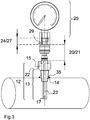
- the Figure 3 shows an embodiment of the device of the invention disposed on a pipe.
- the elements are thus assembled to ensure the rigidity of the fastening device.
- Part 13 of the thimble is disposed inside the pipe.
- the thimble is thus screwed by the thread 24 in a suitable means welded to the pipe by a weld 35, the portion 15 allowing the operator to perform the clamping of the thimble.
- a protection element 22 is also arranged to protect this part 15.
- the elements 20 and 21 of the manually attachable and detachable fastener are connected to each other. Fixing between the thimble and the appropriate means 35 being of the screw and nut type, the thimble 12 then has a thread 14 allowing the glove finger 12 to be screwed into the appropriate means 35 of the nut type, for example a throttle .
- the portion 15 of the thimble 12, external to the confined medium, is adapted to be surrounded by a clamping tool allowing the operator to tighten or loosen the thimble 12 in the appropriate means 35, nut type.
- This portion 15 of the thimble 12 is hexagonal with a standardized size.
- a portion 13 of the thimble 12 is disposed inside the pipe.
- the thimble 12 is thus screwed by the thread 24 in a suitable nut-type means welded to the pipe, the part 15 allowing the operator to perform the tightening of the thermowell 12.
- a protective element 22 is also arranged to protect this part 15.
- the elements 20 and 21 of the manually attachable and detachable fastener are connected to each other.
- the measuring means 11 is inserted into the cavernous body 17 and screwed between the threads of the connecting elements 24 and the means 27.
- processing and / or display elements use a simple temperature counter.
- the device object of the invention makes it possible to replace a measuring sensor 11, easily and without risk for the operator or the sensor.
Landscapes
- Physics & Mathematics (AREA)
- General Physics & Mathematics (AREA)
- Measuring Fluid Pressure (AREA)
- Testing Or Calibration Of Command Recording Devices (AREA)
Abstract
Description
- L'invention concerne un dispositif de fixation d'un capteur de mesure d'une grandeur physique du contenu d'un milieu confiné. L'invention présente une application particulièrement avantageuse pour monter et démonter un capteur de mesure associé à un doigt de gant.
- Un doigt de gant (en anglais « thimble ») est un tube de petit diamètre fermé à une extrémité et permettant d'effectuer des échanges entre des milieux physiques séparés par sa paroi. Les doigts de gant sont communément utilisés afin de mesurer certaines propriétés d'un contenu dans un milieu confiné sans que la sonde d'un capteur de mesure soit en contact direct avec le fluide présent à l'intérieur du milieu confiné, le milieu confiné pouvant être, par exemple, un réservoir, un tuyau ou une canalisation.
- Par exemple, dans une canalisation, un système de fixation comprenant un doigt de gant peut être mis en place pour permettre à une sonde de mesurer la température d'un fluide circulant dans la canalisation et corriger au besoin le débit du fluide. Pour ce faire la sonde peut être du type thermocouple.
- Les doigts de gant sont généralement fixés mécaniquement sur la paroi du milieu confiné par un moyen approprié soudé sur la paroi du milieu confiné. Généralement la fixation est du type vis et écrou, le doigt de gant possède alors un filetage externe autorisant le vissage du doigt de gant dans le filetage interne d'un moyen approprié de type écrou, par exemple un thrédolet. Une partie du doigt de gant, externe au milieu confiné, est apte à être entourée par un outil de serrage permettant à l'exploitant de serrer ou desserrer la fixation du doigt de gant dans le moyen approprié. Généralement, cette partie du doigt de gant possède un périmètre hexagonal et une taille normalisée.
- Régulièrement, il est constaté des incidents ou accidents lors de démontage de sonde disposée dans un doigt de gant. En effet, afin de démonter en toute sécurité un capteur de mesure fixé sur un doigt de gant, il faut utiliser une clé pour dévisser le capteur de mesure et une contre-clé pour maintenir en place le doigt de gant dans le moyen approprié. Toutefois, il arrive que la contre-clé soit oubliée et que le doigt de gant se dévisse à la place du capteur de mesure. Il arrive aussi que l'exploitant se trompe et dévisse directement le doigt de gant au lieu du capteur de mesure. Si une erreur intervient dans le démontage du capteur de mesure, cela peut engendrer un risque mécanique, thermique ou chimique selon les propriétés du liquide ou du gaz contenu dans le milieu confiné.
- En outre, une autre difficulté liée aux sondes visées dans les doigts de gant est rencontrée lors du démontage des sondes avec câblage : le câblage de la sonde doit être déconnecté avant le dévissage afin d'éviter de tordre le câble. Cette déconnection électrique supplémentaire ajoute des contraintes de type consignation électrique, habilitation électrique de l'exploitant, outillage, temps d'exécution ...
- L'invention propose de remplacer la fixation de type vis et écrou permettant d'associer classiquement le capteur de mesure au doigt de gant par une fixation attachable et détachable manuellement.
- A cet effet, l'invention vise un dispositif de fixation d'un capteur de mesure d'une grandeur physique du contenu d'un milieu confiné,
- ledit dispositif de fixation comportant un doigt de gant fixé sur une paroi du milieu confiné et comportant une partie pénétrante dans le milieu confiné,
- ledit capteur de mesure comportant une sonde disposée à l'intérieur de la partie pénétrante du doigt de gant,
- On comprend par fixation attachable et détachable manuellement tous les systèmes mécaniques permettant à un exploitant de force moyenne d'attacher le capteur de mesure au doigt de gant ou de détacher le capteur de mesure du doigt de gant sans utiliser un outil. Les systèmes mécaniques peuvent être du type clipsage, crochet, emmanchement en force... L'invention répond alors au problème des risques encourus par l'exploitant lors du montage et du démontage du capteur de mesure.
- On note que le capteur de mesure comprend la sonde, un élément d'assemblage au dispositif et, éventuellement, des éléments de traitement, de transmission et/ou d'affichage de valeurs mesurées. Le doigt de gant peut être fixé sur une paroi du milieu confiné par un moyen approprié, par exemple de type écrou.
- Dans des modes de réalisation, la fixation attachable et détachable manuellement comporte un premier élément relié au doigt de gant et un deuxième élément relié au capteur de mesure. Cette réalisation présente l'avantage de résoudre les contraintes de déconnection électrique de la sonde puisque cette déconnexion peut être effectuée dans une manipulation sans action de vissage donc sans torsion du câblage.
- Par exemple, le dispositif de fixation par serrage de stries annulaires nécessite la disposition d'un élément mâle et d'un élément femelle. Ce dispositif de fixation par serrage de stries annulaires peut être mis en place pour garantir une bonne résistance à la pression. Il existe d'autres systèmes par clipsage moins coûteux tels que les raccords à billes, ressort, bague, raccord lisse avec joint torique...
- Dans des modes de réalisation, les éléments de la fixation attachable et détachable manuellement sont aptes à être associés et dissociés avec un mouvement manuel comportant une rotation inférieure à un demi-tour, ce qui permet à l'utilisateur de ne pas lâcher l'un des éléments de fixation pendant la solidarisation ou la désolidarisation des éléments de de la fixation. Ce mode de réalisation préférentiel de la fixation, attachable et détachable manuellement, exclu les associations par vissage qui présentent les mêmes risques que l'art antérieur : c'est-à-dire un dévissage du mauvais élément et une torsion possible d'un câblage et d'un connecteur électriques.
- Dans des modes de réalisation, le doigt de gant et le premier élément de la fixation sont réalisés en une seule pièce monobloc. Cette réalisation présente l'avantage de réduire le nombre de pièces vissées du dispositif de fixation et ainsi de réduire le risque de mauvais dévissage. De plus, cette réalisation améliore la rigidité du dispositif de fixation. Cette solution est envisagée pour mettre en place le dispositif de l'invention dans un milieu confiné ou pour remplacer un dispositif de fixation existant.
- Dans des modes de réalisation, le dispositif de fixation objet de l'invention comporte un raccord d'assemblage intermédiaire entre le doigt de gant et le premier élément de la fixation. Cette réalisation permet de réaliser les deux pièces séparément. Cette solution est envisagée pour remplacer en partie un dispositif de fixation existant et mettre en place le dispositif objet de l'invention.
- Dans des modes de réalisation, le raccord d'assemblage intermédiaire entre le doigt de gant et le premier élément de la fixation comporte un filetage. Le raccord d'assemblage comporte ainsi une extrémité est de type vis ou, en variante, écrou. Ces modes de réalisation présentent l'avantage de ne pas modifier les doigts de gant existants, munis d'un filetage, pour la mise en oeuvre du dispositif objet de l'invention.
- Dans des modes de réalisation, un élément de protection est déployé sur une partie du doigt de gant apte à être entourée par un outil de serrage. La partie du doigt de gant apte à être entourée par un outil de serrage présente, par exemple, un périmètre hexagonal permettant à l'exploitant de monter ou démonter le doigt de gant dans un moyen approprié, de type écrou, au moyen d'un outil de serrage, par exemple une clé. L'élément de protection, par exemple de type « jupe » en matière plastique, permet de protéger la partie du doigt de gant apte à recevoir l'outil de serrage mais également la partie du doigt de gant en contact avec le moyen approprié.
- Dans des modes de réalisation, le dispositif de fixation objet de l'invention comporte un moyen apte à garantir la non étanchéité de la fixation attachable et détachable manuellement. En cas de fissuration du doigt de gant, il peut y avoir présence coté sonde d'un fluide sous pression. Cette réalisation présente l'avantage d'éviter, dans ce cas, les risques de projection lors du démontage de la fixation attachable et détachable manuellement.
- Dans des modes de réalisation, le moyen apte à garantir la non étanchéité de la fixation attachable et détachable manuellement comporte des trous permanents.
- Dans des modes de réalisation, le moyen apte à garantir la non étanchéité de la fixation attachable et détachable manuellement comporte au moins une soupape ou un disque de rupture. Grâce à chacune de ces dispositions, le fluide anormalement présent dans le doigt de gant est ainsi purgé par la fixation sans être projeté sur l'utilisateur.
- L'invention sera mieux comprise à la lecture de la description qui suit et à l'examen des figures qui l'accompagnent. Ces figures ne sont données qu'à titre illustratif mais nullement limitatif de l'invention. Elles montrent :
-
Figure 1 : une représentation schématique des éléments d'un mode de réalisation particulier du dispositif objet de l'invention permettant de remplacer un système de fixation existant ; -
Figure 2 : une représentation schématique des éléments d'un mode de réalisation particulier du dispositif objet de l'invention permettant de remplacer en partie un système de fixation existant et -
Figure 3 : une représentation schématique des éléments d'un mode de réalisation particulier du dispositif objet de l'invention dans une réalisation de l'invention. - Les éléments identiques, similaires ou analogues, conservent les mêmes références d'une Figure à l'autre.
- Les figures ne sont pas à l'échelle.
- La
Figure 1 montre une représentation schématique des éléments d'un mode de réalisation particulier du dispositif objet de l'invention permettant de remplacer un système de fixation existant. LaFigure 1 montre ainsi le dispositif 10 de fixation objet de l'invention et le capteur 11 de mesure d'une grandeur physique du contenu d'un milieu confiné. Le milieu confiné peut être un réservoir, un tuyau, une canalisation. - Le dispositif 10 de fixation comporte un doigt de gant 12 composé d'une partie pénétrante 13 dans le milieu confiné et d'une partie 15 apte à être entourée par un outil de serrage. La partie 15 du doigt de gant 12 apte à être entourée par un outil de serrage possède, par exemple, un périmètre hexagonal permettant à l'exploitant de monter ou démonter le doigt de gant 12 dans le moyen approprié, au moyen d'une clé. La liaison mécanique entre le doigt de gant 12 et le moyen approprié est du type vis et écrou, la partie pénétrante 13 comportant un filetage 14 biseauté correspondant au moyen approprié.
- Le doigt de gant 12 possède un corps caverneux 17 permettant d'accueillir une sonde 23 du capteur de mesure 11 apte à mesurer certaines grandeurs physiques d'un contenu dans le milieu confiné sans que la sonde 23 soit en contact direct avec le fluide présent à l'intérieur du milieu confiné.
- Un élément 22 de protection, par exemple de type « jupe » en matière plastique, permet de protéger la partie du doigt de gant 12 apte à être entourée par un outil de serrage mais également la partie du doigt de gant 12 en contact avec le moyen approprié.
- Le capteur 11 de mesure comprend la sonde 23, les éléments d'assemblage 24 avec le dispositif 10 de fixation et les éléments 25 de traitement et/ou d'affichage. Les éléments d'assemblage 24 sont reliés avec le dispositif 10 de fixation par les moyens 27 d'installation du capteur 11 de mesure. Par exemple, les éléments d'assemblage 24 et les moyens 27 peuvent présenter un filetage commun permettant de visser le moyen 11 dans le dispositif 10 de fixation.
- Le dispositif objet de l'invention propose de relier le capteur 11 de mesure au doigt de gant 12 par une fixation attachable et détachable manuellement. Plus précisément, la fixation attachable et détachable manuellement permet de relier directement le capteur 11 de mesure au doigt de gant 12. On comprend par fixation attachable et détachable manuellement tout les systèmes mécaniques permettant à un exploitant de force moyenne d'attacher ou de détacher le capteur 11 de mesure avec le doigt de gant 12 sans utiliser un outil. Les systèmes mécaniques peuvent être du type clipsage, crochet, emmanchement en force ... Il est ainsi possible d'installer un capteur 11 de mesure, ou de remplacer uniquement le capteur 11 de mesure par un nouveau capteur 11 de mesure, sans difficulté pour un exploitant.
- Par exemple, la
Figure 1 montre une fixation par serrage de stries annulaires. Un élément 20 mâle, faisant partie du doigt de gant 12, peut pénétrer dans un élément 21 femelle. Les stries annulaires du dispositif de fixation 10 assurent alors le maintien des éléments 20 mâle et 21 femelle ensemble, réalisées en acier inoxydable, grâce à un joint torique en élastomère nitrile. De plus, le joint torique assure l'étanchéité de la liaison entre les éléments 20 male et 21 femelle. Cette fixation par serrage de stries annulaires permet une bonne résistance à la pression et une simplicité de manipulation par l'exploitant. - En cas de fissuration du doigt de gant 12, il peut y avoir présence coté sonde 23 d'un fluide sous pression. Pour palier à ce problème, le dispositif 10 de fixation objet de l'invention comporte, dans des variantes, un moyen 29 apte à garantir la non étanchéité de la fixation attachable et détachable manuellement.
- Ce moyen 29 peut être composé de trous permanents permettant au fluide anormalement présent dans le doigt de gant 12 d'être évacué sans être projeté vers l'utilisateur. Ce moyen 29 peut également être composé d'au moins une soupape ou d'un disque de rupture permettant au fluide anormalement présent dans le doigt de gant 12 d'être purgé du dispositif 10 de fixation.
- Sur la
Figure 1 , le doigt de gant 12 et le premier élément 20 de la fixation sont réalisés en une seule pièce monobloc. Cette réalisation présente un avantage de rigidité du dispositif 10 de fixation. Cette solution est envisagée pour mettre en place le dispositif objet de l'invention dans un milieu confiné ou pour remplacer un dispositif 10 de fixation existant. - Sur la
Figure 2 , le dispositif 10 de fixation objet de l'invention comporte un raccord 31 d'assemblage intermédiaire entre un doigt de gant 12' et le premier élément 20 de la fixation. Cette réalisation permet de réaliser les deux pièces séparément. Cette solution est envisagée pour remplacer en partie un dispositif 10 de fixation existant et mettre en place un dispositif selon l'invention. - Dans les deux modes de réalisation, les éléments 20 et 21 de la fixation attachable et détachable manuellement sont aptes à être associés et dissociés avec un mouvement manuel comportant une rotation inférieure à un demi-tour, ce qui permet à l'utilisateur de ne pas lâcher l'un des éléments de fixation pendant la solidarisation ou la désolidarisation des éléments de de la fixation. Un seul mouvement suffit ainsi à la fixation et au détachement des éléments de fixation.
- Sur la
Figure 2 , le raccord 31 d'assemblage intermédiaire entre le doigt de gant et le premier élément 20 de la fixation est de type vis ou, en variante, écrou. Le raccord 31 d'assemblage présente alors un filetage externe correspondant au filetage interne 32 du doigt de gant 12'. Ce mode de réalisation présente l'avantage de ne pas avoir à modifier les doigts de gant 12' existant, dotés d'un filetage, pour la mise en oeuvre d'un dispositif selon l'invention. Cependant, cette solution est moins préférentielle car la sonde 23' doit être plus longue qu'une sonde 23 classique pour être adaptée à pénétrer jusqu'au fond du corps caverneux 17. L'élément 22' de protection doit également être adapté pour cette solution. - La
Figure 3 montre un exemple de réalisation du dispositif objet de l'invention disposé sur un tuyau. Les éléments sont ainsi assemblés pour assurer la rigidité du dispositif 10 de fixation. Une partie 13 du doigt de gant est disposée à l'intérieur du tuyau. Le doigt de gant est ainsi vissé par le filetage 24 dans un moyen approprié soudé au tuyau par une soudure 35, la partie 15 permettant à l'exploitant d'effectuer le serrage du doigt de gant. Un élément 22 de protection est également disposé pour protéger cette partie 15. - Les éléments 20 et 21 de la fixation attachable et détachable manuellement sont connectés entre eux. La fixation entre le doigt de gant et le moyen approprié 35 étant du type vis et écrou, le doigt de gant 12 possède alors un filetage 14 autorisant le vissage du doigt de gant 12 dans le moyen approprié 35 de type écrou, par exemple un thrédolet.
- La partie 15 du doigt de gant 12, externe au milieu confiné, est apte à être entourée par un outil de serrage permettant à l'exploitant de serrer ou desserrer le doigt de gant 12 dans le moyen approprié 35, de type écrou. Cette partie 15 du doigt de gant 12 est hexagonale avec une taille normalisée.
- Les éléments sont ainsi assemblés pour assurer la rigidité du dispositif 10 de fixation. Une partie 13 du doigt de gant 12 est disposée à l'intérieur du tuyau. Le doigt de gant 12 est ainsi vissé par le filetage 24 dans un moyen approprié de type écrou soudé au tuyau, la partie 15 permettant à l'exploitant d'effectuer le serrage du doigt de gant 12. Un élément 22 de protection est également disposé pour protéger cette partie 15.
- Les éléments 20 et 21 de la fixation attachable et détachable manuellement sont connectés entre eux. Le moyen 11 de mesure est inséré dans le corps caverneux 17 et vissé entre les filetages des éléments d'assemblage 24 et des moyens 27. On retrouve également la présence du moyen 29 apte à garantir la non étanchéité de la fixation attachable et détachable manuellement.
- En outre, les éléments 25 de traitement et/ou d'affichage utilisent un simple compteur de température.
- Grace à la fixation attachable et détachable manuellement, le dispositif objet de l'invention permet de remplacer un capteur 11 de mesure, facilement et sans risque pour l'exploitant ou le capteur.
Claims (10)
- Dispositif (10) de fixation d'un capteur (11) de mesure d'une grandeur physique du contenu d'un milieu confiné,- ledit dispositif (10) de fixation comportant un doigt de gant (12, 12') fixé sur une paroi du milieu confiné et comportant une partie (13) pénétrante dans le milieu confiné,- ledit capteur (11) de mesure comportant une sonde (23, 23') disposée à l'intérieur de la partie (13) pénétrante du doigt de gant (12, 12'),
caractérisé en ce que le capteur (11) de mesure est relié au doigt (12, 12') de gant par une fixation attachable et détachable manuellement. - Dispositif (10) de fixation selon la revendication 1, dans lequel la fixation attachable et détachable manuellement comporte un premier élément (20) relié au doigt de gant (12, 12') et un deuxième élément (21) relié au capteur (11) de mesure.
- Dispositif (10) de fixation selon la revendication 2, dans lequel les éléments (20, 21) de la fixation attachable et détachable manuellement sont aptes à être associés et dissociés avec un mouvement manuel comportant une rotation inférieure à un demi-tour.
- Dispositif (10) de fixation selon l'une des revendications 2 ou 3, dans lequel le doigt de gant (12) et le premier élément (20) de la fixation sont réalisés en une seule pièce monobloc.
- Dispositif (10) de fixation selon l'une des revendications 2 ou 3, qui comporte un raccord (31) d'assemblage intermédiaire entre le doigt de gant (12') et le premier élément (20) de la fixation.
- Dispositif (10) de fixation selon la revendication 5, dans lequel le raccord (31) d'assemblage intermédiaire entre le doigt de gant (12') et le premier élément (20) de la fixation comporte un filetage.
- Dispositif (10) de fixation selon l'une des revendications 1 à 6, qui comporte un élément (22, 22') de protection déployé sur une partie du doigt de gant (12, 12') apte à être entourée par un outil de serrage.
- Dispositif (10) de fixation selon d'une des revendications 1 à 7, qui comporte un moyen (29) apte à garantir la non étanchéité de la fixation attachable et détachable manuellement.
- Dispositif (10) de fixation selon la revendication 8, dans lequel le moyen (29) apte à garantir la non étanchéité de la fixation attachable et détachable manuellement comporte des trous permanents.
- Dispositif (10) de fixation selon la revendication 8, dans lequel le moyen (29) apte à garantir la non étanchéité de la fixation attachable et détachable manuellement comporte au moins une soupape ou un disque de rupture.
Applications Claiming Priority (1)
| Application Number | Priority Date | Filing Date | Title |
|---|---|---|---|
| FR1152884A FR2973505B1 (fr) | 2011-04-04 | 2011-04-04 | Dispositif de fixation d'un capteur de mesure d'une grandeur physique du contenu d'un milieu confine. |
Publications (2)
| Publication Number | Publication Date |
|---|---|
| EP2508849A1 true EP2508849A1 (fr) | 2012-10-10 |
| EP2508849B1 EP2508849B1 (fr) | 2020-05-27 |
Family
ID=45894709
Family Applications (1)
| Application Number | Title | Priority Date | Filing Date |
|---|---|---|---|
| EP12163077.6A Active EP2508849B1 (fr) | 2011-04-04 | 2012-04-04 | Dispositif de fixation d'un capteur de mesure d'une grandeur physique du contenu d'un milieu confine |
Country Status (2)
| Country | Link |
|---|---|
| EP (1) | EP2508849B1 (fr) |
| FR (1) | FR2973505B1 (fr) |
Citations (3)
| Publication number | Priority date | Publication date | Assignee | Title |
|---|---|---|---|---|
| US3462315A (en) * | 1965-08-26 | 1969-08-19 | Pall Corp | Swing mounted thermocouple assembly |
| CH521657A (de) * | 1970-12-14 | 1972-04-15 | Proton Ag | Messwertgebereinrichtung mit herausnehmbarer Messwertgebersonde |
| US5456761A (en) * | 1993-07-15 | 1995-10-10 | Alcan International Limited | High temperature and abrasion resistant temperature measuring device |
-
2011
- 2011-04-04 FR FR1152884A patent/FR2973505B1/fr active Active
-
2012
- 2012-04-04 EP EP12163077.6A patent/EP2508849B1/fr active Active
Patent Citations (3)
| Publication number | Priority date | Publication date | Assignee | Title |
|---|---|---|---|---|
| US3462315A (en) * | 1965-08-26 | 1969-08-19 | Pall Corp | Swing mounted thermocouple assembly |
| CH521657A (de) * | 1970-12-14 | 1972-04-15 | Proton Ag | Messwertgebereinrichtung mit herausnehmbarer Messwertgebersonde |
| US5456761A (en) * | 1993-07-15 | 1995-10-10 | Alcan International Limited | High temperature and abrasion resistant temperature measuring device |
Also Published As
| Publication number | Publication date |
|---|---|
| EP2508849B1 (fr) | 2020-05-27 |
| FR2973505A1 (fr) | 2012-10-05 |
| FR2973505B1 (fr) | 2013-05-10 |
Similar Documents
| Publication | Publication Date | Title |
|---|---|---|
| CN103339432B (zh) | 手工上紧的液压配件 | |
| EP2369216B1 (fr) | Appareil de fixation d'un dispositif sur une structure circulaire | |
| US20130181445A1 (en) | Fitting for jacketed conduits | |
| US9279526B2 (en) | Apparatuses and methods for providing finger-tightened and ratchet-secured connections between conduits | |
| CN101326393B (zh) | 管接头锁定装置 | |
| CA2779014A1 (fr) | Raccord anti-rotation sans fil de verrouillage | |
| US20130263674A1 (en) | Tube or pipe clamp with a force measurement device | |
| FR2973094A3 (fr) | Dispositif de raccordement pour les conduites rigides ou flexibles avec indicateur de l'etat de montage | |
| JP5198837B2 (ja) | 継手への二重管の接続構造及び継手 | |
| EP2508849B1 (fr) | Dispositif de fixation d'un capteur de mesure d'une grandeur physique du contenu d'un milieu confine | |
| JP5522006B2 (ja) | 温度センサーの端部保持部材の取付構造 | |
| US9964246B2 (en) | Hose crimp fitting or hydraulic adaptors that utilize a reverse threaded lock nut that engages to a JIC nut or similar swivel nut to prevent the nut from loosening | |
| CN205192630U (zh) | 一种温度传感器探头旋转限位结构 | |
| WO2007063717A1 (fr) | Structure d’accouplement | |
| JP2009115160A (ja) | ガスケット、および、これを用いた管継手 | |
| KR101232319B1 (ko) | 파이프 연결구 | |
| US9109738B2 (en) | Sealing plug for quick closing coupling system | |
| FR2964721A1 (fr) | Un dispositif pour interdire le desserrage et le demontage d'un raccordement souple de gaz sur l'alimentation du reseau gaz en cuivre rigide, et assurer la securite normative du raccordement | |
| JP5127327B2 (ja) | トロリ線温度検出装置 | |
| EP0995945B1 (fr) | Manomètre encastrable pour dispositif de distribution de fluide sous pression, notamment pour détendeur de gaz | |
| EP2591269B1 (fr) | Collier de dérivation pour une canalisation de fluide, eau ou gaz par exemple | |
| JP2016017771A (ja) | 配管密閉性検査用プラグ | |
| JP5395970B2 (ja) | 管継手及び閉鎖バルブ | |
| JP2013245695A (ja) | 管体連結具、管体連結方法 | |
| JP5593170B2 (ja) | 流体温度測定装置 |
Legal Events
| Date | Code | Title | Description |
|---|---|---|---|
| PUAI | Public reference made under article 153(3) epc to a published international application that has entered the european phase |
Free format text: ORIGINAL CODE: 0009012 |
|
| 17P | Request for examination filed |
Effective date: 20120404 |
|
| AK | Designated contracting states |
Kind code of ref document: A1 Designated state(s): AL AT BE BG CH CY CZ DE DK EE ES FI FR GB GR HR HU IE IS IT LI LT LU LV MC MK MT NL NO PL PT RO RS SE SI SK SM TR |
|
| AX | Request for extension of the european patent |
Extension state: BA ME |
|
| STAA | Information on the status of an ep patent application or granted ep patent |
Free format text: STATUS: EXAMINATION IS IN PROGRESS |
|
| 17Q | First examination report despatched |
Effective date: 20170314 |
|
| GRAP | Despatch of communication of intention to grant a patent |
Free format text: ORIGINAL CODE: EPIDOSNIGR1 |
|
| STAA | Information on the status of an ep patent application or granted ep patent |
Free format text: STATUS: GRANT OF PATENT IS INTENDED |
|
| INTG | Intention to grant announced |
Effective date: 20191217 |
|
| GRAS | Grant fee paid |
Free format text: ORIGINAL CODE: EPIDOSNIGR3 |
|
| GRAA | (expected) grant |
Free format text: ORIGINAL CODE: 0009210 |
|
| STAA | Information on the status of an ep patent application or granted ep patent |
Free format text: STATUS: THE PATENT HAS BEEN GRANTED |
|
| AK | Designated contracting states |
Kind code of ref document: B1 Designated state(s): AL AT BE BG CH CY CZ DE DK EE ES FI FR GB GR HR HU IE IS IT LI LT LU LV MC MK MT NL NO PL PT RO RS SE SI SK SM TR |
|
| REG | Reference to a national code |
Ref country code: GB Ref legal event code: FG4D Free format text: NOT ENGLISH |
|
| REG | Reference to a national code |
Ref country code: CH Ref legal event code: EP |
|
| REG | Reference to a national code |
Ref country code: DE Ref legal event code: R096 Ref document number: 602012070298 Country of ref document: DE |
|
| REG | Reference to a national code |
Ref country code: AT Ref legal event code: REF Ref document number: 1275006 Country of ref document: AT Kind code of ref document: T Effective date: 20200615 |
|
| REG | Reference to a national code |
Ref country code: GR Ref legal event code: EP Ref document number: 20200402300 Country of ref document: GR Effective date: 20201014 |
|
| REG | Reference to a national code |
Ref country code: LT Ref legal event code: MG4D |
|
| PG25 | Lapsed in a contracting state [announced via postgrant information from national office to epo] |
Ref country code: NO Free format text: LAPSE BECAUSE OF FAILURE TO SUBMIT A TRANSLATION OF THE DESCRIPTION OR TO PAY THE FEE WITHIN THE PRESCRIBED TIME-LIMIT Effective date: 20200827 Ref country code: IS Free format text: LAPSE BECAUSE OF FAILURE TO SUBMIT A TRANSLATION OF THE DESCRIPTION OR TO PAY THE FEE WITHIN THE PRESCRIBED TIME-LIMIT Effective date: 20200927 Ref country code: PT Free format text: LAPSE BECAUSE OF FAILURE TO SUBMIT A TRANSLATION OF THE DESCRIPTION OR TO PAY THE FEE WITHIN THE PRESCRIBED TIME-LIMIT Effective date: 20200928 Ref country code: FI Free format text: LAPSE BECAUSE OF FAILURE TO SUBMIT A TRANSLATION OF THE DESCRIPTION OR TO PAY THE FEE WITHIN THE PRESCRIBED TIME-LIMIT Effective date: 20200527 Ref country code: SE Free format text: LAPSE BECAUSE OF FAILURE TO SUBMIT A TRANSLATION OF THE DESCRIPTION OR TO PAY THE FEE WITHIN THE PRESCRIBED TIME-LIMIT Effective date: 20200527 Ref country code: LT Free format text: LAPSE BECAUSE OF FAILURE TO SUBMIT A TRANSLATION OF THE DESCRIPTION OR TO PAY THE FEE WITHIN THE PRESCRIBED TIME-LIMIT Effective date: 20200527 |
|
| REG | Reference to a national code |
Ref country code: NL Ref legal event code: MP Effective date: 20200527 |
|
| PG25 | Lapsed in a contracting state [announced via postgrant information from national office to epo] |
Ref country code: BG Free format text: LAPSE BECAUSE OF FAILURE TO SUBMIT A TRANSLATION OF THE DESCRIPTION OR TO PAY THE FEE WITHIN THE PRESCRIBED TIME-LIMIT Effective date: 20200827 Ref country code: RS Free format text: LAPSE BECAUSE OF FAILURE TO SUBMIT A TRANSLATION OF THE DESCRIPTION OR TO PAY THE FEE WITHIN THE PRESCRIBED TIME-LIMIT Effective date: 20200527 Ref country code: LV Free format text: LAPSE BECAUSE OF FAILURE TO SUBMIT A TRANSLATION OF THE DESCRIPTION OR TO PAY THE FEE WITHIN THE PRESCRIBED TIME-LIMIT Effective date: 20200527 Ref country code: HR Free format text: LAPSE BECAUSE OF FAILURE TO SUBMIT A TRANSLATION OF THE DESCRIPTION OR TO PAY THE FEE WITHIN THE PRESCRIBED TIME-LIMIT Effective date: 20200527 |
|
| REG | Reference to a national code |
Ref country code: AT Ref legal event code: MK05 Ref document number: 1275006 Country of ref document: AT Kind code of ref document: T Effective date: 20200527 |
|
| PG25 | Lapsed in a contracting state [announced via postgrant information from national office to epo] |
Ref country code: AL Free format text: LAPSE BECAUSE OF FAILURE TO SUBMIT A TRANSLATION OF THE DESCRIPTION OR TO PAY THE FEE WITHIN THE PRESCRIBED TIME-LIMIT Effective date: 20200527 Ref country code: NL Free format text: LAPSE BECAUSE OF FAILURE TO SUBMIT A TRANSLATION OF THE DESCRIPTION OR TO PAY THE FEE WITHIN THE PRESCRIBED TIME-LIMIT Effective date: 20200527 |
|
| PG25 | Lapsed in a contracting state [announced via postgrant information from national office to epo] |
Ref country code: DK Free format text: LAPSE BECAUSE OF FAILURE TO SUBMIT A TRANSLATION OF THE DESCRIPTION OR TO PAY THE FEE WITHIN THE PRESCRIBED TIME-LIMIT Effective date: 20200527 Ref country code: ES Free format text: LAPSE BECAUSE OF FAILURE TO SUBMIT A TRANSLATION OF THE DESCRIPTION OR TO PAY THE FEE WITHIN THE PRESCRIBED TIME-LIMIT Effective date: 20200527 Ref country code: EE Free format text: LAPSE BECAUSE OF FAILURE TO SUBMIT A TRANSLATION OF THE DESCRIPTION OR TO PAY THE FEE WITHIN THE PRESCRIBED TIME-LIMIT Effective date: 20200527 Ref country code: SM Free format text: LAPSE BECAUSE OF FAILURE TO SUBMIT A TRANSLATION OF THE DESCRIPTION OR TO PAY THE FEE WITHIN THE PRESCRIBED TIME-LIMIT Effective date: 20200527 Ref country code: CZ Free format text: LAPSE BECAUSE OF FAILURE TO SUBMIT A TRANSLATION OF THE DESCRIPTION OR TO PAY THE FEE WITHIN THE PRESCRIBED TIME-LIMIT Effective date: 20200527 Ref country code: AT Free format text: LAPSE BECAUSE OF FAILURE TO SUBMIT A TRANSLATION OF THE DESCRIPTION OR TO PAY THE FEE WITHIN THE PRESCRIBED TIME-LIMIT Effective date: 20200527 Ref country code: RO Free format text: LAPSE BECAUSE OF FAILURE TO SUBMIT A TRANSLATION OF THE DESCRIPTION OR TO PAY THE FEE WITHIN THE PRESCRIBED TIME-LIMIT Effective date: 20200527 |
|
| PG25 | Lapsed in a contracting state [announced via postgrant information from national office to epo] |
Ref country code: SK Free format text: LAPSE BECAUSE OF FAILURE TO SUBMIT A TRANSLATION OF THE DESCRIPTION OR TO PAY THE FEE WITHIN THE PRESCRIBED TIME-LIMIT Effective date: 20200527 Ref country code: PL Free format text: LAPSE BECAUSE OF FAILURE TO SUBMIT A TRANSLATION OF THE DESCRIPTION OR TO PAY THE FEE WITHIN THE PRESCRIBED TIME-LIMIT Effective date: 20200527 |
|
| REG | Reference to a national code |
Ref country code: DE Ref legal event code: R097 Ref document number: 602012070298 Country of ref document: DE |
|
| PLBE | No opposition filed within time limit |
Free format text: ORIGINAL CODE: 0009261 |
|
| STAA | Information on the status of an ep patent application or granted ep patent |
Free format text: STATUS: NO OPPOSITION FILED WITHIN TIME LIMIT |
|
| 26N | No opposition filed |
Effective date: 20210302 |
|
| PG25 | Lapsed in a contracting state [announced via postgrant information from national office to epo] |
Ref country code: SI Free format text: LAPSE BECAUSE OF FAILURE TO SUBMIT A TRANSLATION OF THE DESCRIPTION OR TO PAY THE FEE WITHIN THE PRESCRIBED TIME-LIMIT Effective date: 20200527 |
|
| PG25 | Lapsed in a contracting state [announced via postgrant information from national office to epo] |
Ref country code: MC Free format text: LAPSE BECAUSE OF FAILURE TO SUBMIT A TRANSLATION OF THE DESCRIPTION OR TO PAY THE FEE WITHIN THE PRESCRIBED TIME-LIMIT Effective date: 20200527 |
|
| GBPC | Gb: european patent ceased through non-payment of renewal fee |
Effective date: 20210404 |
|
| PG25 | Lapsed in a contracting state [announced via postgrant information from national office to epo] |
Ref country code: LU Free format text: LAPSE BECAUSE OF NON-PAYMENT OF DUE FEES Effective date: 20210404 |
|
| REG | Reference to a national code |
Ref country code: BE Ref legal event code: MM Effective date: 20210430 |
|
| PG25 | Lapsed in a contracting state [announced via postgrant information from national office to epo] |
Ref country code: GB Free format text: LAPSE BECAUSE OF NON-PAYMENT OF DUE FEES Effective date: 20210404 |
|
| PG25 | Lapsed in a contracting state [announced via postgrant information from national office to epo] |
Ref country code: IE Free format text: LAPSE BECAUSE OF NON-PAYMENT OF DUE FEES Effective date: 20210404 |
|
| PG25 | Lapsed in a contracting state [announced via postgrant information from national office to epo] |
Ref country code: BE Free format text: LAPSE BECAUSE OF NON-PAYMENT OF DUE FEES Effective date: 20210430 |
|
| PG25 | Lapsed in a contracting state [announced via postgrant information from national office to epo] |
Ref country code: HU Free format text: LAPSE BECAUSE OF FAILURE TO SUBMIT A TRANSLATION OF THE DESCRIPTION OR TO PAY THE FEE WITHIN THE PRESCRIBED TIME-LIMIT; INVALID AB INITIO Effective date: 20120404 Ref country code: CY Free format text: LAPSE BECAUSE OF FAILURE TO SUBMIT A TRANSLATION OF THE DESCRIPTION OR TO PAY THE FEE WITHIN THE PRESCRIBED TIME-LIMIT Effective date: 20200527 |
|
| PG25 | Lapsed in a contracting state [announced via postgrant information from national office to epo] |
Ref country code: MK Free format text: LAPSE BECAUSE OF FAILURE TO SUBMIT A TRANSLATION OF THE DESCRIPTION OR TO PAY THE FEE WITHIN THE PRESCRIBED TIME-LIMIT Effective date: 20200527 |
|
| PG25 | Lapsed in a contracting state [announced via postgrant information from national office to epo] |
Ref country code: TR Free format text: LAPSE BECAUSE OF FAILURE TO SUBMIT A TRANSLATION OF THE DESCRIPTION OR TO PAY THE FEE WITHIN THE PRESCRIBED TIME-LIMIT Effective date: 20200527 |
|
| PG25 | Lapsed in a contracting state [announced via postgrant information from national office to epo] |
Ref country code: MT Free format text: LAPSE BECAUSE OF FAILURE TO SUBMIT A TRANSLATION OF THE DESCRIPTION OR TO PAY THE FEE WITHIN THE PRESCRIBED TIME-LIMIT Effective date: 20200527 |
|
| PGFP | Annual fee paid to national office [announced via postgrant information from national office to epo] |
Ref country code: DE Payment date: 20250528 Year of fee payment: 14 |
|
| PGFP | Annual fee paid to national office [announced via postgrant information from national office to epo] |
Ref country code: IT Payment date: 20250425 Year of fee payment: 14 |
|
| PGFP | Annual fee paid to national office [announced via postgrant information from national office to epo] |
Ref country code: FR Payment date: 20250429 Year of fee payment: 14 |
|
| PGFP | Annual fee paid to national office [announced via postgrant information from national office to epo] |
Ref country code: GR Payment date: 20250425 Year of fee payment: 14 |
|
| PGFP | Annual fee paid to national office [announced via postgrant information from national office to epo] |
Ref country code: CH Payment date: 20250602 Year of fee payment: 14 |