EP2508426B1 - Flow device and method and system using the flow device - Google Patents
Flow device and method and system using the flow device Download PDFInfo
- Publication number
- EP2508426B1 EP2508426B1 EP20120163280 EP12163280A EP2508426B1 EP 2508426 B1 EP2508426 B1 EP 2508426B1 EP 20120163280 EP20120163280 EP 20120163280 EP 12163280 A EP12163280 A EP 12163280A EP 2508426 B1 EP2508426 B1 EP 2508426B1
- Authority
- EP
- European Patent Office
- Prior art keywords
- cantilevered tabs
- outer perimeter
- opening
- tabs
- cantilevered
- Prior art date
- Legal status (The legal status is an assumption and is not a legal conclusion. Google has not performed a legal analysis and makes no representation as to the accuracy of the status listed.)
- Not-in-force
Links
Images

Classifications
-
- B—PERFORMING OPERATIONS; TRANSPORTING
- B64—AIRCRAFT; AVIATION; COSMONAUTICS
- B64D—EQUIPMENT FOR FITTING IN OR TO AIRCRAFT; FLIGHT SUITS; PARACHUTES; ARRANGEMENT OR MOUNTING OF POWER PLANTS OR PROPULSION TRANSMISSIONS IN AIRCRAFT
- B64D15/00—De-icing or preventing icing on exterior surfaces of aircraft
- B64D15/02—De-icing or preventing icing on exterior surfaces of aircraft by ducted hot gas or liquid
- B64D15/04—Hot gas application
-
- B—PERFORMING OPERATIONS; TRANSPORTING
- B64—AIRCRAFT; AVIATION; COSMONAUTICS
- B64D—EQUIPMENT FOR FITTING IN OR TO AIRCRAFT; FLIGHT SUITS; PARACHUTES; ARRANGEMENT OR MOUNTING OF POWER PLANTS OR PROPULSION TRANSMISSIONS IN AIRCRAFT
- B64D33/00—Arrangement in aircraft of power plant parts or auxiliaries not otherwise provided for
- B64D33/02—Arrangement in aircraft of power plant parts or auxiliaries not otherwise provided for of combustion air intakes
- B64D2033/0233—Arrangement in aircraft of power plant parts or auxiliaries not otherwise provided for of combustion air intakes comprising de-icing means
-
- Y—GENERAL TAGGING OF NEW TECHNOLOGICAL DEVELOPMENTS; GENERAL TAGGING OF CROSS-SECTIONAL TECHNOLOGIES SPANNING OVER SEVERAL SECTIONS OF THE IPC; TECHNICAL SUBJECTS COVERED BY FORMER USPC CROSS-REFERENCE ART COLLECTIONS [XRACs] AND DIGESTS
- Y10—TECHNICAL SUBJECTS COVERED BY FORMER USPC
- Y10T—TECHNICAL SUBJECTS COVERED BY FORMER US CLASSIFICATION
- Y10T137/00—Fluid handling
- Y10T137/1624—Destructible or deformable element controlled
- Y10T137/1632—Destructible element
Definitions
- the present invention generally relates to flow devices used in a fluid system, and more particularly to a flow device that is adapted to restrict flow of a fluid within a system and further capable of responding to an over-pressure condition in the system.
- a portion of the air compressed by the fan and/or compressor of a gas turbine engine is typically used for various purposes, including cooling of engine components and, in the case of aircraft engines, use in anti-icing and de-icing systems and cabin pressurization.
- FIG. 1 schematically represents a high-bypass turbofan engine 10 as including a large fan 12 placed at the front of the engine 10 to compress incoming air 14.
- the core engine 16 is represented as including a compressor section 18 containing low and high pressure compressor stages that further compress the air, a combustion chamber 20 where fuel is mixed with the compressed air and combusted, and a turbine section 22 where high and low pressure turbines extract energy from the combustion gases to drive, respectively, the high pressure stage of the compressor section 18 and the fan 12 and low pressure stage of the compressor section 18.
- the fan 12 is surrounded by a nacelle or fan cowling 24 that, in combination with a core cowling 26 surrounding the core engine 16, defines a bypass duct 28 through which the bulk of the compressed fan air flows toward the rear of the engine 10.
- FIG. 1 schematically represents bleed air flow that is drawn from the compressor section 18 and delivered through a duct 32 to an annular-shaped cavity 34, sometimes referred to as the D-duct, defined between the inlet lip 36 of the fan cowling 24 and a bulkhead 38 within the fan cowling 24.
- the hot bleed air can be discharged through a plenum 40 (as represented in FIG. 1 ) toward the internal surfaces of the inlet lip 36, resulting in heating of the lip 36 to remove and/or prevent ice formation.
- the spent bleed air then exits the D-duct 34 through, for example, one or more vents (not shown).
- compressed air from the compressor section 18 as well as the fan 12 can be bled for various other purposes and therefore used by various other regions of the engine 10.
- bleed air from the fan bypass duct 28 is often ducted to the core compartment 30 within the core cowling 26 to cool the engine control and various other components (not shown) located within the compartment 30.
- the location and configuration of the duct 32 is a nonlimiting example of a duct intended to deliver bleed air within an aircraft engine.
- air bled from the fan 12 or compressor section 18 may require pressure or flow regulation, such as with a valve or a bleed orifice.
- the plenum 40 represented in FIG. 1 may be configured as a manifold or one of multiple nozzles (not shown) to serve as a flow restrictor to control the flow rate of bleed air to the D-duct 34.
- provisions may be required to ensure that the bleed air does not exceed some pressure limit, for example, the structural capability of the fan cowling 24.
- various types of pressure relief valves and "blowout" doors have been developed and used. For example, U.S. Patent No.
- 3,571,977 discloses a pressure release door to prevent the over-pressurization of a pressurized compartment, such as within a nacelle of an aircraft engine to prevent the failure of skin panels and other major structural components of the nacelle if an over-pressurization event were to occur. While effective for their intended purpose, blowout doors and pressure relief valves add complexity and weight to an aircraft engine, all of which is detrimental to the cost and operation of the aircraft.
- EP 0,560,612 A1 discloses a backdraught shutter for a ventilating fan of the type commonly used to ventilate a room of a building.
- the backdraught shutter serves the function of helping to avoid a backdraught of cold air through the fan when the fan is not operating; for example, when the fan is mounted to an external wall or window.
- a first aspect of the present invention provides an aircraft engine in accordance with claim 1 herein.
- a second aspect of the present invention provides a method of inhibiting ice build-up on a fan cowling of an aircraft engine, the method being in accordance with claim 7 herein.
- An advantage of this invention the ability of the flow device to function in a largely conventional manner as a flow restrictor within a flowing fluid system, as well as provide a pressure relief function in the event that a predetermined pressure level is exceeded within the fluid system.
- the flow device can be implemented without significantly increasing the complexity or weight of the fluid system.
- the flow device can also be implemented with fewer components than conventional pressure relief devices, including pressure relief valves and blowout doors commonly used in aircraft applications.
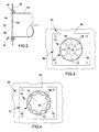
- FIGS. 2 through 4 schematically represent a flow device 50 according to an embodiment of the present invention.
- the flow device 50 can be employed in an anti-icing (and de-icing) system of the type represented in FIG. 1 , and for convenience will be discussed with reference to the engine 10 in FIG. 1 .
- the invention is suitable for use in a variety of other applications in which flow restriction of a fluid is desired as well as protection from over-pressurization conditions, including but not limited to bleed air drawn from the compressor 18 or bypass duct 28 for use by various other regions of the engine 10.
- FIG. 2 schematically represents the flow device 50 as mounted to a wall 46 and receiving bleed air from a passage 48.
- the wall 46 may be a wall of the plenum 40 in FIG. 1 and the passage 48 may be the duct 32 of FIG. 1 , in which case the device 50 operates as a component of the anti-icing system of FIG. 1 .
- bleed air drawn from the compressor section 18 is discharged through the device 50 into the D-duct (cavity) 34, resulting in the inlet lip 36 (not shown) being heated to remove and/or prevent ice formation on the fan cowling 24 and, more particularly, the inlet lip 36 of the cowling 24.
- the bleed air discharged into the D-duct 34 may require pressure or flow regulation, and for this purpose the flow device 50 is configured to serve as one of any number of flow restrictors that control the flow rate of hot bleed air discharged into the D-duct 34. In addition to its flow restrictor function, the flow device 50 is configured to have a pressure relief function to prevent an over-pressurization condition within the duct 32 or plenum 40.
- the flow device 50 is in the form of a flat panel 52 in which an opening 54 is defined.
- the panel 52 can be formed of a variety of materials, with stainless steels being notable but nonlimiting examples.
- the panel 52 is preferably flat as shown, though it is foreseeable that nonplanar shapes could be possible.
- the panel 52 defines a base region 56 that surrounds the opening 52, as well as a plurality of tabs 58 that are cantilevered from the base region 56 and extend toward the opening 54, such that in combination the innermost ends 60 of the tabs 58 define the opening 54.
- the base region 56 can be utilized to mount the device 50 to the inboard wall 46.
- the tabs 58 generally lie in the same plane. Eight tabs 58 are represented in FIGS. 3 and 4 , though it is foreseeable that more or fewer tabs 58 could be utilized.
- the tabs 58 adjoin the base region 56 at what will be termed an outer perimeter 62 of an expandable orifice 64, which is defined by, in combination, the opening 54, the tabs 58 and the outer perimeter 62, that latter of which defines junctions 66 between the base region 56 and tabs 58 at which the tabs 58 are able to pivot or bend relative to the base region 56.
- the panel 52 or at least that portion of the panel 52 defining the junctions 66 has a through-thickness that enables the tabs 58 to pivot relative to the base region 56 when subjected to a sufficiently high force or pressure, which in effect establishes a predetermined pressure level above which the opening 54 expands as a result of the tabs 58 deflecting in response to an over-pressurization condition, as represented in FIG. 4 .
- a suitable predetermined pressure level for a particular application can be arrived at by tailoring the device 60 through choices of dimensions and/or materials, as well as modeling techniques and/or limited experimentation.
- the opening 54 and perimeter 62 are represented in FIGS. 3 and 4 as circular and, because they coincide with the perimeter 62, the junctions 66 between the base region 56 and tabs 58 are arcuate in shape. However, it should be appreciated that other geometric shapes are possible for the expandable orifice 64 and its elements. Also as a result of the circular shapes of the opening 54 and perimeter 62, the tabs 58 are wedge-shaped and extend radially inward toward a central axis of the opening 54, which may be parallel to the through-thickness direction of the panel 52. FIG.
- FIGS. 3 and 4 also represents circumferentially adjacent pairs of the tabs 58 as entirely separated from each other by a gap 68, which enables the tabs 58 to deflect out-of-plane relative to the base region 56 and independently of each other.
- the gaps 68 are located on radials of the axis of the opening 54.
- FIGS. 3 and 4 further show the tabs 58 as being partially delineated by peripheral gaps 70 that are disposed on the perimeter 62 of the expandable orifice 64.
- Each of these gaps 70 is contiguous with one of the radial gaps 68 between adjacent pairs of the tabs 58, such that the junction 66 of each tab 58 is between circumferentially-spaced pairs of the peripheral gaps 70.
- the junctions 66 and peripheral gaps 70 have roughly equal circumferential lengths. In practice, it is foreseeable that the circumferential lengths of the junctions 66 could be greater or less than that of the peripheral gaps 70.
- the opening 54 of the expandable orifice 64 is operable to restrict a fluid flowing through the orifice 64 while the pressure of the fluid remains below a predetermined pressure level
- the tabs 58 are operable to deflect out of the plane of the panel 52, causing the opening 54 to increase in cross-sectional area (and diameter) to relieve an over-pressure condition if the fluid pressure were to exceed the predetermined pressure level.
- the predetermined pressure level at which the tabs 58 will deflect depends on such factors as the relative cross-sectional areas of the opening 54 and tabs 58, the surface area of each tab 58, and the relative circumferential lengths of the junctions 66 and the peripheral gaps 70.
- the pressure level at which the orifice 64 is desired to expand can vary, though a threshold pressure within a range of about 0.1 to about 40 psi (about 700 Pa to about 0.3 MPa) will be typical.
- suitable thicknesses for the panel 52 will typically be in a range of about 0.04 to about 0.15 inch (about 1 to about 4 millimeters), more preferably about 0.08 to about 0.1 inch (about 2 to about 2.5 millimeters), suitable diameters for the opening 54 will typically be in a range of about 0.02 to about 1.5 inch (about 0.5 millimeters to about 4 centimeters), for example about 0.5 inch (about 0.06 millimeter), and suitable diameters for the perimeter 62 will typically be in a range of about 0.05 to about 4 inches (about 1.25 millimeters to about 10 centimeters), for example about 1.5 inches (about 4 centimeters).
- the radial and peripheral gaps 68 and 70 preferably have widths on the order of about 0.005 to about 0.045 inch (about 125 micrometers to about 1.1 millimeters).
- operation of the aircraft engine 10 results in bleed air being drawn from the compressor section 18 and through the duct 32, at which point the bleed air is discharged into the D-duct 34 of the fan cowling 24 through the flow device 50.
- the opening 54 serves to restrict the flow of the bleed air through the expandable orifice 64 while the pressure of the bleed air remains below the predetermined pressure level established by the design of the orifice 64.
- the opening 54 expands to relieve the over-pressure condition as a result of the tabs 58 being deflected relative to the base region 56.
- the radial gaps 68 enable the tabs 58 to deflect independently of each other. Deflection of the tabs 58 will typically result in plastic deformation of their junctions 66 with the base region 56, in which case the opening 54 will not return to its original cross-sectional area intended to serve as a flow restrictor. As such, it will typically be necessary to replace of the flow device 50 in the event that an over-pressure condition occurs. Due to its uncomplicated design and construction, the cost of replacing the flow device 50 will pose minimal inconvenience.
- the flow device 50 could be employed in applications outside the aerospace industry, the physical configuration of the flow device 50 and structures to which it is mounted could differ from what is shown in the Figures, and materials and processes other than those noted could be used to fabricate the device 50.
- the device 50 could be used in any high pressure fluid system containing essentially any type of fluid (gases and liquids) to protect against failure of an upstream pressure regulating device and avoid a burst event by relieving the pressure. Therefore, the scope of the invention is to be limited only by the following claims.
Landscapes
- Engineering & Computer Science (AREA)
- Aviation & Aerospace Engineering (AREA)
- Structures Of Non-Positive Displacement Pumps (AREA)
- Pipe Accessories (AREA)
- Safety Valves (AREA)
Applications Claiming Priority (1)
| Application Number | Priority Date | Filing Date | Title |
|---|---|---|---|
| US13/080,864 US8387950B2 (en) | 2011-04-06 | 2011-04-06 | Flow device and method and system using the flow device |
Publications (2)
| Publication Number | Publication Date |
|---|---|
| EP2508426A1 EP2508426A1 (en) | 2012-10-10 |
| EP2508426B1 true EP2508426B1 (en) | 2014-07-02 |
Family
ID=46022045
Family Applications (1)
| Application Number | Title | Priority Date | Filing Date |
|---|---|---|---|
| EP20120163280 Not-in-force EP2508426B1 (en) | 2011-04-06 | 2012-04-05 | Flow device and method and system using the flow device |
Country Status (4)
| Country | Link |
|---|---|
| US (1) | US8387950B2 (enExample) |
| EP (1) | EP2508426B1 (enExample) |
| JP (1) | JP5925561B2 (enExample) |
| CA (1) | CA2773964C (enExample) |
Families Citing this family (16)
| Publication number | Priority date | Publication date | Assignee | Title |
|---|---|---|---|---|
| US9879599B2 (en) * | 2012-09-27 | 2018-01-30 | United Technologies Corporation | Nacelle anti-ice valve utilized as compressor stability bleed valve during starting |
| FR3007738B1 (fr) | 2013-06-28 | 2015-07-31 | Aircelle Sa | Dispositif de degivrage et de conditionnement pour aeronef |
| US9764847B2 (en) * | 2013-10-18 | 2017-09-19 | The Boeing Company | Anti-icing system for aircraft |
| EP3084179B1 (en) | 2013-12-16 | 2020-02-05 | United Technologies Corporation | Fan nacelle inlet flow control |
| US20150216076A1 (en) | 2014-01-30 | 2015-07-30 | International Business Machines Corporation | Resilient deformable air valve |
| US10144520B2 (en) * | 2014-04-14 | 2018-12-04 | Rohr, Inc. | De-icing system with thermal management |
| ITUB20151085A1 (it) * | 2015-05-28 | 2016-11-28 | Alenia Aermacchi Spa | Gondola per motore aeronautico con sistema antighiaccio utilizzante un fluido bifase. |
| US10487740B2 (en) * | 2015-06-17 | 2019-11-26 | Hamilton Sundstrand Corporation | Multi-flapper check valve without center supports |
| CN105539861A (zh) * | 2015-12-11 | 2016-05-04 | 中国航空工业集团公司西安飞机设计研究所 | 一种根据气压差进气的活门装置 |
| US10634060B2 (en) * | 2016-11-20 | 2020-04-28 | Mra Systems, Llc | Engine door with burst seal |
| BE1025263B1 (fr) * | 2017-05-31 | 2019-01-07 | Safran Aero Boosters S.A. | Compresseur degivrant de turbomachine et procede de degivrage |
| DE102018112244A1 (de) * | 2018-05-22 | 2019-11-28 | Rolls-Royce Deutschland Ltd & Co Kg | Gasturbinentriebwerk |
| US11220344B2 (en) * | 2018-12-17 | 2022-01-11 | Rohr, Inc. | Anti-ice double walled duct system |
| US12416368B2 (en) * | 2019-01-28 | 2025-09-16 | Mohammad Mohsen Saadat | Blade type check valve |
| FR3116082B1 (fr) * | 2020-11-09 | 2022-09-30 | Safran Aircraft Engines | Turboréacteur à double flux pourvu de moyens de communication d’air |
| US11808290B1 (en) * | 2020-12-18 | 2023-11-07 | University Of South Florida | Fluid flow conditioning apparatus |
Family Cites Families (15)
| Publication number | Priority date | Publication date | Assignee | Title |
|---|---|---|---|---|
| US2593315A (en) * | 1946-10-31 | 1952-04-15 | Dole Valve Co | Flow control device |
| US3571977A (en) | 1969-06-27 | 1971-03-23 | Boeing Co | Access and pressure release door latch mechanism |
| US3698598A (en) * | 1971-07-26 | 1972-10-17 | Black Sivalls & Bryson Inc | Safety pressure relief device |
| US4688745A (en) * | 1986-01-24 | 1987-08-25 | Rohr Industries, Inc. | Swirl anti-ice system |
| JPS63128391U (enExample) * | 1987-02-16 | 1988-08-22 | ||
| US5284012A (en) | 1991-05-16 | 1994-02-08 | General Electric Company | Nacelle cooling and ventilation system |
| GB2265001A (en) * | 1992-03-12 | 1993-09-15 | Hunter International | A backdraught shutter for a ventilating fan |
| EP0847510B1 (fr) | 1995-09-01 | 2003-04-16 | Climes Conseil, Claude Liardet | Valve |
| US6688558B2 (en) | 1999-11-23 | 2004-02-10 | The Boeing Company | Method and apparatus for aircraft inlet ice protection |
| US6371411B1 (en) * | 1999-11-23 | 2002-04-16 | The Boeing Company | Method and apparatus for aircraft inlet ice protection |
| FR2823533B1 (fr) * | 2001-04-17 | 2003-08-08 | Eads Airbus Sa | Capot d'entree d'air pour moteur a reaction, pourvu de moyens de degivrage |
| WO2003074947A1 (en) | 2002-03-07 | 2003-09-12 | Fujitsu Limited | Backflow preventer and electronic apparatus |
| US7275560B2 (en) | 2004-09-29 | 2007-10-02 | A.J. Manufacturing, Inc. | Pressure relief door for air duct work |
| CN101861555B (zh) * | 2007-11-15 | 2013-03-27 | 贝利莫控股公司 | 限流器 |
| US7740075B2 (en) | 2008-07-09 | 2010-06-22 | Schlumberger Technology Corporation | Pressure relief actuated valves |
-
2011
- 2011-04-06 US US13/080,864 patent/US8387950B2/en active Active
-
2012
- 2012-04-03 JP JP2012084401A patent/JP5925561B2/ja not_active Expired - Fee Related
- 2012-04-05 CA CA 2773964 patent/CA2773964C/en not_active Expired - Fee Related
- 2012-04-05 EP EP20120163280 patent/EP2508426B1/en not_active Not-in-force
Also Published As
| Publication number | Publication date |
|---|---|
| US8387950B2 (en) | 2013-03-05 |
| JP5925561B2 (ja) | 2016-05-25 |
| US20120255274A1 (en) | 2012-10-11 |
| CA2773964C (en) | 2014-12-16 |
| EP2508426A1 (en) | 2012-10-10 |
| JP2012229690A (ja) | 2012-11-22 |
| CA2773964A1 (en) | 2012-10-06 |
Similar Documents
| Publication | Publication Date | Title |
|---|---|---|
| EP2508426B1 (en) | Flow device and method and system using the flow device | |
| US9771873B2 (en) | Bifurcation fairing | |
| EP3084183B1 (en) | Heat exchanger flow control assembly and corresponding method | |
| US11162417B2 (en) | Scoop inlet | |
| US10125683B2 (en) | De-icing and conditioning device for an aircraft | |
| US8052377B2 (en) | Cowling arrangement | |
| US7596938B2 (en) | Turbomachine with a deflector system | |
| US10473031B2 (en) | Systems and methods for preventing fuel leakage in a gas turbine engine | |
| EP2610471B1 (en) | Variable area fan nozzle | |
| US10634060B2 (en) | Engine door with burst seal | |
| EP3219957B1 (en) | Thermal management system for deicing aircraft with temperature based flow restrictor | |
| EP2891769B1 (en) | A bleed flow outlet | |
| WO2011123106A1 (en) | Turbine blade tip clearance control | |
| EP3254953B1 (en) | Thermal insulaton blanket | |
| WO2018038909A1 (en) | Air intake systems and methods of assembly thereof | |
| EP3087269B1 (en) | Aircraft with injection cooling system and injection cooling system | |
| EP3828078B1 (en) | Gas turbine engine, nacelle thereof, and associated method of operating a gas turbine engine | |
| US11492998B2 (en) | Flexible aft cowls for aircraft | |
| US20220177149A1 (en) | Air inlet duct for a nacelle of an aircraft propulsion assembly | |
| US8408009B2 (en) | Cooling air bleed device in a turbine engine | |
| EP3421774B1 (en) | Aircraft incorporating a low-temperature bleed system | |
| EP3019724B1 (en) | Preloaded aft vent area for low pressure fan ducts | |
| CN114340999A (zh) | 用于涡轮机的短舱的内部结构 | |
| EP3632791B1 (en) | Nacelle inlet with reinforcement structure | |
| US20170342907A1 (en) | Fire shield integrated to fuel nozzle retaining bracket |
Legal Events
| Date | Code | Title | Description |
|---|---|---|---|
| PUAI | Public reference made under article 153(3) epc to a published international application that has entered the european phase |
Free format text: ORIGINAL CODE: 0009012 |
|
| AK | Designated contracting states |
Kind code of ref document: A1 Designated state(s): AL AT BE BG CH CY CZ DE DK EE ES FI FR GB GR HR HU IE IS IT LI LT LU LV MC MK MT NL NO PL PT RO RS SE SI SK SM TR |
|
| AX | Request for extension of the european patent |
Extension state: BA ME |
|
| 17P | Request for examination filed |
Effective date: 20130410 |
|
| RIC1 | Information provided on ipc code assigned before grant |
Ipc: B64D 15/04 20060101AFI20131211BHEP Ipc: F16K 15/03 20060101ALI20131211BHEP |
|
| GRAP | Despatch of communication of intention to grant a patent |
Free format text: ORIGINAL CODE: EPIDOSNIGR1 |
|
| INTG | Intention to grant announced |
Effective date: 20140226 |
|
| GRAS | Grant fee paid |
Free format text: ORIGINAL CODE: EPIDOSNIGR3 |
|
| GRAA | (expected) grant |
Free format text: ORIGINAL CODE: 0009210 |
|
| AK | Designated contracting states |
Kind code of ref document: B1 Designated state(s): AL AT BE BG CH CY CZ DE DK EE ES FI FR GB GR HR HU IE IS IT LI LT LU LV MC MK MT NL NO PL PT RO RS SE SI SK SM TR |
|
| REG | Reference to a national code |
Ref country code: GB Ref legal event code: FG4D |
|
| REG | Reference to a national code |
Ref country code: CH Ref legal event code: EP Ref country code: AT Ref legal event code: REF Ref document number: 675764 Country of ref document: AT Kind code of ref document: T Effective date: 20140715 |
|
| REG | Reference to a national code |
Ref country code: IE Ref legal event code: FG4D |
|
| REG | Reference to a national code |
Ref country code: DE Ref legal event code: R096 Ref document number: 602012002272 Country of ref document: DE Effective date: 20140814 |
|
| REG | Reference to a national code |
Ref country code: AT Ref legal event code: MK05 Ref document number: 675764 Country of ref document: AT Kind code of ref document: T Effective date: 20140702 |
|
| REG | Reference to a national code |
Ref country code: NL Ref legal event code: VDEP Effective date: 20140702 |
|
| REG | Reference to a national code |
Ref country code: LT Ref legal event code: MG4D |
|
| PG25 | Lapsed in a contracting state [announced via postgrant information from national office to epo] |
Ref country code: BG Free format text: LAPSE BECAUSE OF FAILURE TO SUBMIT A TRANSLATION OF THE DESCRIPTION OR TO PAY THE FEE WITHIN THE PRESCRIBED TIME-LIMIT Effective date: 20141002 Ref country code: PT Free format text: LAPSE BECAUSE OF FAILURE TO SUBMIT A TRANSLATION OF THE DESCRIPTION OR TO PAY THE FEE WITHIN THE PRESCRIBED TIME-LIMIT Effective date: 20141103 Ref country code: LT Free format text: LAPSE BECAUSE OF FAILURE TO SUBMIT A TRANSLATION OF THE DESCRIPTION OR TO PAY THE FEE WITHIN THE PRESCRIBED TIME-LIMIT Effective date: 20140702 Ref country code: ES Free format text: LAPSE BECAUSE OF FAILURE TO SUBMIT A TRANSLATION OF THE DESCRIPTION OR TO PAY THE FEE WITHIN THE PRESCRIBED TIME-LIMIT Effective date: 20140702 Ref country code: SE Free format text: LAPSE BECAUSE OF FAILURE TO SUBMIT A TRANSLATION OF THE DESCRIPTION OR TO PAY THE FEE WITHIN THE PRESCRIBED TIME-LIMIT Effective date: 20140702 Ref country code: CZ Free format text: LAPSE BECAUSE OF FAILURE TO SUBMIT A TRANSLATION OF THE DESCRIPTION OR TO PAY THE FEE WITHIN THE PRESCRIBED TIME-LIMIT Effective date: 20140702 Ref country code: GR Free format text: LAPSE BECAUSE OF FAILURE TO SUBMIT A TRANSLATION OF THE DESCRIPTION OR TO PAY THE FEE WITHIN THE PRESCRIBED TIME-LIMIT Effective date: 20141003 Ref country code: FI Free format text: LAPSE BECAUSE OF FAILURE TO SUBMIT A TRANSLATION OF THE DESCRIPTION OR TO PAY THE FEE WITHIN THE PRESCRIBED TIME-LIMIT Effective date: 20140702 Ref country code: NO Free format text: LAPSE BECAUSE OF FAILURE TO SUBMIT A TRANSLATION OF THE DESCRIPTION OR TO PAY THE FEE WITHIN THE PRESCRIBED TIME-LIMIT Effective date: 20141002 |
|
| PG25 | Lapsed in a contracting state [announced via postgrant information from national office to epo] |
Ref country code: LV Free format text: LAPSE BECAUSE OF FAILURE TO SUBMIT A TRANSLATION OF THE DESCRIPTION OR TO PAY THE FEE WITHIN THE PRESCRIBED TIME-LIMIT Effective date: 20140702 Ref country code: RS Free format text: LAPSE BECAUSE OF FAILURE TO SUBMIT A TRANSLATION OF THE DESCRIPTION OR TO PAY THE FEE WITHIN THE PRESCRIBED TIME-LIMIT Effective date: 20140702 Ref country code: CY Free format text: LAPSE BECAUSE OF FAILURE TO SUBMIT A TRANSLATION OF THE DESCRIPTION OR TO PAY THE FEE WITHIN THE PRESCRIBED TIME-LIMIT Effective date: 20140702 Ref country code: NL Free format text: LAPSE BECAUSE OF FAILURE TO SUBMIT A TRANSLATION OF THE DESCRIPTION OR TO PAY THE FEE WITHIN THE PRESCRIBED TIME-LIMIT Effective date: 20140702 Ref country code: AT Free format text: LAPSE BECAUSE OF FAILURE TO SUBMIT A TRANSLATION OF THE DESCRIPTION OR TO PAY THE FEE WITHIN THE PRESCRIBED TIME-LIMIT Effective date: 20140702 Ref country code: IS Free format text: LAPSE BECAUSE OF FAILURE TO SUBMIT A TRANSLATION OF THE DESCRIPTION OR TO PAY THE FEE WITHIN THE PRESCRIBED TIME-LIMIT Effective date: 20141102 Ref country code: HR Free format text: LAPSE BECAUSE OF FAILURE TO SUBMIT A TRANSLATION OF THE DESCRIPTION OR TO PAY THE FEE WITHIN THE PRESCRIBED TIME-LIMIT Effective date: 20140702 Ref country code: PL Free format text: LAPSE BECAUSE OF FAILURE TO SUBMIT A TRANSLATION OF THE DESCRIPTION OR TO PAY THE FEE WITHIN THE PRESCRIBED TIME-LIMIT Effective date: 20140702 |
|
| REG | Reference to a national code |
Ref country code: DE Ref legal event code: R097 Ref document number: 602012002272 Country of ref document: DE |
|
| PG25 | Lapsed in a contracting state [announced via postgrant information from national office to epo] |
Ref country code: SK Free format text: LAPSE BECAUSE OF FAILURE TO SUBMIT A TRANSLATION OF THE DESCRIPTION OR TO PAY THE FEE WITHIN THE PRESCRIBED TIME-LIMIT Effective date: 20140702 Ref country code: RO Free format text: LAPSE BECAUSE OF FAILURE TO SUBMIT A TRANSLATION OF THE DESCRIPTION OR TO PAY THE FEE WITHIN THE PRESCRIBED TIME-LIMIT Effective date: 20140702 Ref country code: EE Free format text: LAPSE BECAUSE OF FAILURE TO SUBMIT A TRANSLATION OF THE DESCRIPTION OR TO PAY THE FEE WITHIN THE PRESCRIBED TIME-LIMIT Effective date: 20140702 Ref country code: DK Free format text: LAPSE BECAUSE OF FAILURE TO SUBMIT A TRANSLATION OF THE DESCRIPTION OR TO PAY THE FEE WITHIN THE PRESCRIBED TIME-LIMIT Effective date: 20140702 Ref country code: IT Free format text: LAPSE BECAUSE OF FAILURE TO SUBMIT A TRANSLATION OF THE DESCRIPTION OR TO PAY THE FEE WITHIN THE PRESCRIBED TIME-LIMIT Effective date: 20140702 |
|
| PLBE | No opposition filed within time limit |
Free format text: ORIGINAL CODE: 0009261 |
|
| STAA | Information on the status of an ep patent application or granted ep patent |
Free format text: STATUS: NO OPPOSITION FILED WITHIN TIME LIMIT |
|
| 26N | No opposition filed |
Effective date: 20150407 |
|
| PG25 | Lapsed in a contracting state [announced via postgrant information from national office to epo] |
Ref country code: SI Free format text: LAPSE BECAUSE OF FAILURE TO SUBMIT A TRANSLATION OF THE DESCRIPTION OR TO PAY THE FEE WITHIN THE PRESCRIBED TIME-LIMIT Effective date: 20140702 Ref country code: MC Free format text: LAPSE BECAUSE OF FAILURE TO SUBMIT A TRANSLATION OF THE DESCRIPTION OR TO PAY THE FEE WITHIN THE PRESCRIBED TIME-LIMIT Effective date: 20140702 Ref country code: LU Free format text: LAPSE BECAUSE OF FAILURE TO SUBMIT A TRANSLATION OF THE DESCRIPTION OR TO PAY THE FEE WITHIN THE PRESCRIBED TIME-LIMIT Effective date: 20150405 |
|
| REG | Reference to a national code |
Ref country code: CH Ref legal event code: PL |
|
| REG | Reference to a national code |
Ref country code: IE Ref legal event code: MM4A |
|
| PG25 | Lapsed in a contracting state [announced via postgrant information from national office to epo] |
Ref country code: LI Free format text: LAPSE BECAUSE OF NON-PAYMENT OF DUE FEES Effective date: 20150430 Ref country code: CH Free format text: LAPSE BECAUSE OF NON-PAYMENT OF DUE FEES Effective date: 20150430 |
|
| REG | Reference to a national code |
Ref country code: FR Ref legal event code: PLFP Year of fee payment: 5 |
|
| PG25 | Lapsed in a contracting state [announced via postgrant information from national office to epo] |
Ref country code: IE Free format text: LAPSE BECAUSE OF NON-PAYMENT OF DUE FEES Effective date: 20150405 |
|
| PG25 | Lapsed in a contracting state [announced via postgrant information from national office to epo] |
Ref country code: BE Free format text: LAPSE BECAUSE OF FAILURE TO SUBMIT A TRANSLATION OF THE DESCRIPTION OR TO PAY THE FEE WITHIN THE PRESCRIBED TIME-LIMIT Effective date: 20140702 |
|
| PG25 | Lapsed in a contracting state [announced via postgrant information from national office to epo] |
Ref country code: MT Free format text: LAPSE BECAUSE OF FAILURE TO SUBMIT A TRANSLATION OF THE DESCRIPTION OR TO PAY THE FEE WITHIN THE PRESCRIBED TIME-LIMIT Effective date: 20140702 |
|
| REG | Reference to a national code |
Ref country code: FR Ref legal event code: PLFP Year of fee payment: 6 |
|
| PG25 | Lapsed in a contracting state [announced via postgrant information from national office to epo] |
Ref country code: SM Free format text: LAPSE BECAUSE OF FAILURE TO SUBMIT A TRANSLATION OF THE DESCRIPTION OR TO PAY THE FEE WITHIN THE PRESCRIBED TIME-LIMIT Effective date: 20140702 Ref country code: HU Free format text: LAPSE BECAUSE OF FAILURE TO SUBMIT A TRANSLATION OF THE DESCRIPTION OR TO PAY THE FEE WITHIN THE PRESCRIBED TIME-LIMIT; INVALID AB INITIO Effective date: 20120405 |
|
| PGFP | Annual fee paid to national office [announced via postgrant information from national office to epo] |
Ref country code: DE Payment date: 20170427 Year of fee payment: 6 Ref country code: FR Payment date: 20170426 Year of fee payment: 6 Ref country code: GB Payment date: 20170427 Year of fee payment: 6 |
|
| PG25 | Lapsed in a contracting state [announced via postgrant information from national office to epo] |
Ref country code: TR Free format text: LAPSE BECAUSE OF FAILURE TO SUBMIT A TRANSLATION OF THE DESCRIPTION OR TO PAY THE FEE WITHIN THE PRESCRIBED TIME-LIMIT Effective date: 20140702 |
|
| PG25 | Lapsed in a contracting state [announced via postgrant information from national office to epo] |
Ref country code: MK Free format text: LAPSE BECAUSE OF FAILURE TO SUBMIT A TRANSLATION OF THE DESCRIPTION OR TO PAY THE FEE WITHIN THE PRESCRIBED TIME-LIMIT Effective date: 20140702 |
|
| PG25 | Lapsed in a contracting state [announced via postgrant information from national office to epo] |
Ref country code: AL Free format text: LAPSE BECAUSE OF FAILURE TO SUBMIT A TRANSLATION OF THE DESCRIPTION OR TO PAY THE FEE WITHIN THE PRESCRIBED TIME-LIMIT Effective date: 20140702 |
|
| REG | Reference to a national code |
Ref country code: DE Ref legal event code: R119 Ref document number: 602012002272 Country of ref document: DE |
|
| GBPC | Gb: european patent ceased through non-payment of renewal fee |
Effective date: 20180405 |
|
| PG25 | Lapsed in a contracting state [announced via postgrant information from national office to epo] |
Ref country code: DE Free format text: LAPSE BECAUSE OF NON-PAYMENT OF DUE FEES Effective date: 20181101 |
|
| PG25 | Lapsed in a contracting state [announced via postgrant information from national office to epo] |
Ref country code: GB Free format text: LAPSE BECAUSE OF NON-PAYMENT OF DUE FEES Effective date: 20180405 |
|
| PG25 | Lapsed in a contracting state [announced via postgrant information from national office to epo] |
Ref country code: FR Free format text: LAPSE BECAUSE OF NON-PAYMENT OF DUE FEES Effective date: 20180430 |