EP2508362A1 - Motorcycle tire - Google Patents
Motorcycle tire Download PDFInfo
- Publication number
- EP2508362A1 EP2508362A1 EP12161645A EP12161645A EP2508362A1 EP 2508362 A1 EP2508362 A1 EP 2508362A1 EP 12161645 A EP12161645 A EP 12161645A EP 12161645 A EP12161645 A EP 12161645A EP 2508362 A1 EP2508362 A1 EP 2508362A1
- Authority
- EP
- European Patent Office
- Prior art keywords
- angle
- tire
- axially
- axially inner
- degrees
- Prior art date
- Legal status (The legal status is an assumption and is not a legal conclusion. Google has not performed a legal analysis and makes no representation as to the accuracy of the status listed.)
- Granted
Links
Images




Classifications
-
- B—PERFORMING OPERATIONS; TRANSPORTING
- B60—VEHICLES IN GENERAL
- B60C—VEHICLE TYRES; TYRE INFLATION; TYRE CHANGING; CONNECTING VALVES TO INFLATABLE ELASTIC BODIES IN GENERAL; DEVICES OR ARRANGEMENTS RELATED TO TYRES
- B60C11/00—Tyre tread bands; Tread patterns; Anti-skid inserts
- B60C11/03—Tread patterns
- B60C11/0302—Tread patterns directional pattern, i.e. with main rolling direction
-
- B—PERFORMING OPERATIONS; TRANSPORTING
- B60—VEHICLES IN GENERAL
- B60C—VEHICLE TYRES; TYRE INFLATION; TYRE CHANGING; CONNECTING VALVES TO INFLATABLE ELASTIC BODIES IN GENERAL; DEVICES OR ARRANGEMENTS RELATED TO TYRES
- B60C11/00—Tyre tread bands; Tread patterns; Anti-skid inserts
- B60C11/03—Tread patterns
- B60C11/13—Tread patterns characterised by the groove cross-section, e.g. for buttressing or preventing stone-trapping
- B60C11/1307—Tread patterns characterised by the groove cross-section, e.g. for buttressing or preventing stone-trapping with special features of the groove walls
- B60C11/1323—Tread patterns characterised by the groove cross-section, e.g. for buttressing or preventing stone-trapping with special features of the groove walls asymmetric
-
- B—PERFORMING OPERATIONS; TRANSPORTING
- B60—VEHICLES IN GENERAL
- B60C—VEHICLE TYRES; TYRE INFLATION; TYRE CHANGING; CONNECTING VALVES TO INFLATABLE ELASTIC BODIES IN GENERAL; DEVICES OR ARRANGEMENTS RELATED TO TYRES
- B60C11/00—Tyre tread bands; Tread patterns; Anti-skid inserts
- B60C11/03—Tread patterns
- B60C2011/0337—Tread patterns characterised by particular design features of the pattern
- B60C2011/0339—Grooves
- B60C2011/0374—Slant grooves, i.e. having an angle of about 5 to 35 degrees to the equatorial plane
-
- B—PERFORMING OPERATIONS; TRANSPORTING
- B60—VEHICLES IN GENERAL
- B60C—VEHICLE TYRES; TYRE INFLATION; TYRE CHANGING; CONNECTING VALVES TO INFLATABLE ELASTIC BODIES IN GENERAL; DEVICES OR ARRANGEMENTS RELATED TO TYRES
- B60C2200/00—Tyres specially adapted for particular applications
- B60C2200/10—Tyres specially adapted for particular applications for motorcycles, scooters or the like
Definitions
- the present invention relates to a motorcycle tire, more particularly to a tread pattern capable of improving high-speed stability and noise performance without sacrificing handling stability and drainage.
- a motorcycle tire (a) wherein as shown in Fig. 8 , the tread portion (b) is provided with a tread pattern comprising a circumferential groove (d) disposed on the tire equator (c) and oblique grooves (e) extending straight from a tread central region to tread shoulder regions so that the change in the tread pattern rigidity from the tread central region to the tread shoulder regions becomes smooth and thereby the handling and stability can be improved.
- an object of the present invention to provide a motorcycle tire, in which the high-speed stability and noise performance can be improved without sacrificing other performance such as handling stability and drainage.
- a motorcycle tire comprises a tread portion whose half region on each side of the tire equator is provided with main oblique grooves and auxiliary oblique grooves each not to protrude from the one half region to the other one half region, the main oblique grooves on both sides of the tire equator are arranged circumferentially of the tire in a staggered manner, each of the auxiliary oblique grooves is disposed between the circumferentially adjacent main oblique grooves so as to incline in the same direction as the main oblique grooves, the axially inner end of each of the main oblique grooves is positioned at a first axial distance of 1 to 4 mm from the tire equator, the axially inner end of each of the auxiliary oblique grooves is positioned at a second axial distance from the tire equator which is more than the first axial distance, each of the main oblique grooves comprises an axially inner part,
- motorcycle tire according to the present invention may be provided with the following optional features:
- the tire equator is not crossed by any of the oblique grooves and there is no circumferential groove extending along the tire equator. Accordingly, the circumferential rigidity of the tread portion is increased in the vicinity of the tire equator, and the high-speed stability can be improved so as to satisfy the requirements of the high-powered motorcycles. Further, as the main and auxiliary oblique grooves are each inclined at at least two different angles, the change in the tread pattern rigidity from the axially inner end thereof towards the tread edge becomes smooth and thereby the handling stability can be improved.
- the axially inner parts of the main and auxiliary oblique grooves are inclined at the relatively small angles with respect to the tire circumferential direction, the drainage or wet performance can be improved. Further, the curved part between the axially inner part and middle part can improve the noise performance.
- the normally inflated unloaded condition is such that the tire is mounted on a standard wheel rim and inflated to a standard pressure but loaded with no tire load.
- the standard wheel rim is a wheel rim officially approved or recommended for the tire by standards organizations, i.e. JATMA (Japan and Asia), T&RA (North America), ETRTO (Europe), TRAA (Australia), STRO (Scandinavia), ALAPA (Latin America), ITTAC (India) and the like which are effective in the area where the tire is manufactured, sold or used.
- the standard pressure is the maximum air pressure load for the tire specified by the same organization in the Air-pressure/Maximum-load Table or similar list.
- the standard wheel rim is the "standard rim” specified in JATMA, the “Measuring Rim” in ETRTO, the “Design Rim” in TRA or the like.
- the standard pressure is the "maximum air pressure” in JATMA, the “Inflation Pressure” in ETRTO, the maximum pressure given in the "Tire Load Limits at various cold Inflation Pressures" table in TRA or the like.
- a motorcycle tire 1 comprises a tread portion 2, a pair of axially spaced bead portions 4 each with a bead core 5 therein, a pair of sidewall portions 3 extending between the tread edges and the bead portions 4, a carcass 6 extending between the bead portions 4 through the tread portion 2 and sidewall portions 3, and a belt 7 disposed radially outside the carcass 6 in the tread portion 2.
- the tread portion 2 is convexly curved so that the tread face 2S between the tread edges 2t is curved like an arc swelling radially outwardly as a characteristic of a motorcycle tire, and the maximum cross sectional width of the tire occurs between the tread edges 2t, namely, the maximum cross sectional width of the tire equals to the axial tread width TW.
- the carcass 6 is composed of a single ply 6A of carcass cords arranged at an angle of from 75 to 90 degrees, preferably 80 to 90 degrees with respect to the tire equator C, and extending between the bead portions 4 through the tread portion 2 and sidewall portions 3, and further turned up around the bead core 5 in each of the bead portions 4 so as to form a pair of turned up portions 6b and a main portion 6a therebetween.
- organic fiber cords such as nylon, polyester and rayon can be used suitably.
- the bead portions 4 are each provided between the carcass ply main portion 6a and turned up portion 6b with a bead apex 8 made of hard rubber extending radially outwardly in a tapered manner from the bead core.
- the belt 7 is composed of at least one ply (in this example, two cross plies 7A and 7B) of belt cords laid at an angle of 5 to 40 degrees with respect to the tire equator.
- the belt cords steel cords, aramid cords, rayon cords or the like can be used suitably.
- the tread portion 2 is provided with tread grooves defining a unidirectional tread pattern having an intended or designed rotational direction R.
- the tread grooves in this embodiment are main oblique grooves 11 and auxiliary oblique grooves 12. There is no groove other than the oblique grooves 11 and 12.
- the main oblique grooves 11 are left-hand first main oblique grooves 11A disposed within a left half E1 of the tread portion 2 on the left side of the tire equator C, and right-hand second main oblique grooves 11B disposed within a right half E2 of the tread portion 2 on the right side of the tire equator C.
- the left-hand main oblique grooves 11A and the right-hand main oblique grooves 11B are arraigned circumferentially of the tire in a staggered manner.
- the configuration of the left-hand main oblique groove 11A and the configuration of the right-hand main oblique grooves 11B are symmetrical about the tire equator C.
- the main oblique groove 11 (11A, 11B) has a maximum groove width W1 of about 3.5 to 5.0 mm, and a maximum groove depth D1 of about 3.5 to 5.0 mm.
- the main oblique groove 11 (11A, 11B) has a groove bottom 13 and a pair of groove sidewalls 14. As shown in Fig. 3(a) , in a cross section perpendicular to the widthwise center line of the groove, the groove sidewalls 14 extend from the groove bottom 13 to the tread surface 2S, while inclining outwardly with respect to a normal line to the tread surface.
- one of the groove sidewalls 14 to be located on the heel-side S1 (or trailing edge side) in the intended tire rotational direction is called “heel-side groove sidewall 14A”
- the other to be located on the toe-side S2 (or leading edge side) in the intended tire rotational direction is called “toe-side groove sidewall 14B”.
- the angle ⁇ 1a of the heel-side groove sidewall 14A with respect to a normal line to the tread surface is set to be more than the angle ⁇ 1b of the toe-side groove sidewall 14B with respect to a normal line to the tread surface.
- the angle ⁇ 1a of the heel-side groove sidewall 14A is 5 to 30 degrees
- the angle ⁇ 1b of the toe-side groove sidewall 14B is 0 to 5 degrees.
- main oblique grooves 11A and 11B By configuring the main oblique grooves 11A and 11B in this way, it becomes possible to lessen the deformation (from the heel-side S1 toward the toe-side S2) of ground contacting tread elements formed between the main oblique grooves 11, and accordingly to increase the circumferential rigidity of such tread elements. Therefore, it becomes possible to improve the high-speed stability.
- the axially inner end 11Ai of the left-hand main oblique groove 11A is positioned at an axial distance L1a of from 1 to 4 mm from the tire equator C not to extend beyond the tire equator C from E1 side to E2 side as shown in Fig. 1 .
- the axially inner end 11Bi of the right-hand main oblique groove 11B is positioned at an axial distance L1b of from 1 to 4 mm from the tire equator C not to extend beyond the tire equator C from E2 side to E1 side.
- the distances L1a and L1b are not less than 1.5 mm, and not more than 3.5 mm.
- Such main oblique grooves 11A and 11B can maintain the circumferential rigidity of the tread portion 2 in the vicinity of the tire equator C, and thereby the high-speed stability can be improved.
- the distance (L1a, L1b) is less than 1 mm, then it becomes difficult to improve the high-speed stability. If the distance (L1a, L1b) is more than 4 mm, then the drainage is decreased near the tire equator C and there is a possibility that the wet performance during straight running deteriorates.
- the axially inner end and the axially outer end of a groove or a part of a groove refer to those of the widthwise center line of the groove.
- the main oblique groove 11 (11A, 11B) has a substantially S-shaped configuration and is made up of an axially inner part (15A, 15B) extending axially outwardly from the above-mentioned inner end (11Ai, 11Bi) and inclining at an angle ⁇ 1a of not more than 30 degrees with respect to the tire circumferential direction, a middle part (16A, 16B) connected to the axially inner part (15A, 15B) through an inside curved part ((18A, 18B)) and extending at an angle ⁇ 1b of from 25 to 70 degrees with respect to the tire circumferential direction which is more than angle ⁇ 1a, and an axially outer part (17A, 17B) connected to the middle part (16A, 16B) through an outside curved part (19A, 19B) and extending at an angle ⁇ 1c of not more than 30 degrees with respect to the tire circumferential direction which is less than angle ⁇ 1b.
- the angle ( ⁇ 1a, ⁇ 1b and ⁇ 1c) means the angle of the widthwise center line (11Ac, 11Bc) of the main oblique groove (11A, 11B).
- the axially inner part (15A, 15B) extends at a relatively small angle ⁇ 1a near the tire equator, sufficient drainage is provided in the vicinity of the tire equator without forming a circumferential groove.
- the S-shaped configuration including the curved parts (18A, 18B, 19A, 19B) water existing in the tread center region is effectively led to the tread edges and discharged.
- the change in the tread pattern rigidity in the tire axial direction becomes smooth and the handling stability can be improved. Further, tread pattern noise can be improved.
- the angle ⁇ 1a is not more than 25 degrees and not less than 10 degrees.
- the groove width W1 of the axially inner part is gradually decreased from the outer end (15Ao, 15Bo) to the inner end (15Ai, 15Bi) not to decrease the rigidity in the vicinity of the tire equator C as far as possible and so that the change in the tread pattern rigidity form the tire equator C to the outer end (15Ao, 15Bo) becomes smooth and the handling stability can be improved. If the angle ⁇ 1a of the axially inner part (15A, 15B) is more than 30 degrees, it becomes difficult to obtain such advantageous effects.
- the circumferential distance (L2a, L2b) between the axially inner end (15Ai, 15Bi) and outer end (15Ao, 15Bo) of the axially inner part (15A, 15B) is preferably not less than 15 mm, more preferably not less than 17 mm, but not more than 25 mm, more preferably not more than 23 mm.
- the middle part (16A, 16B) extends straight from its axially inner end (16Ai, 16Bi) to outer end (16Ao, 16Bo), while inclining to the rotational direction R at the angle ⁇ 1b (25 to 70 degrees).
- the angle ⁇ 1b is not less than 35 degrees and not more than 65 degrees.
- angle ⁇ 1b of the middle part (16A, 16B) is less than 25 degrees, handling and stability during cornering are liable to deteriorate. If the angle ⁇ 1b is more than 70 degrees, the drainage performance is deteriorated and the tread pattern noise increases.
- the axial distance (L3a, L3b) between the axially inner end (16Ai, 16Bi) and outer end (16Ao, 16Bo) of the middle part (16A, 16B) is preferably set in a range of not less than 50 mm, more preferably not less than 53 mm, but not more than 65 mm, more preferably not more than 62 mm.
- the axially outer part (17A, 17B) extends straight from its axially inner end (17Ai, 17Bi) to outer end (17Ao, 17Bo), while inclining to the rotational direction R at the angle ⁇ 1c (not more than 30 degrees).
- the angle ⁇ 1c not more than 25 degrees and not less than 10 degrees.
- the groove width W1 of the axially outer part (17A, 17B) is gradually decreased from the inner end (17Ai, 17Bi) to the outer end (17Ao, 17Bo) not to decrease the tread pattern rigidity near the tread edge 2t and so that the handling stability can be improved.
- the axially outer parts (17A, 17B) extend at a relatively small angle ⁇ 1c near the tread edges 2t, it is possible to improve the drainage and pattern noise during cornering. If the angle ⁇ 1c of the axially outer part (17A, 17B) exceeds 30 degrees, it becomes difficult to obtain such advantageous effects.
- the circumferential distance (L4a, L4b) between the inner end (17Ai, 17Bi) and outer end (17Ao, 17Bo) of the axially outer part (17A, 17B) is preferably set in a range of not less than 8 mm, more preferably not less than 10 mm, but not more than 16 mm, more preferably not more than 14 mm.
- the inside curved part (18A, 18B) smoothly connects between the axially inner part (15A, 15B) and the middle part (16A, 16B), describing an arc convex toward the heel-side S1.
- the radius of curvature R1a of the widthwise center line of the inside curved part (18A, 18B) is set in a range of not less than 15 mm, more preferably not less than 20 mm, but not more than 30 mm, more preferably not more than 25 mm in view of the drainage, pattern rigidity change, handling stability and noise performance.
- the outside curved part (19A, 19B) smoothly connects between the middle part (16A, 16B) and the axially outer part (17A, 17B), describing an arc convex toward the toe-side S2.
- the radius of curvature R1b of the widthwise center line of the outside curved part (19A, 19B) is set in a range of not less than 15 mm, more preferably not less than 20 mm, but not more than 30 mm, more preferably not more than 25 mm in view of the drainage, handling stability and noise performance.
- auxiliary oblique grooves 12 are left-hand auxiliary oblique grooves 12A arranged alternately with the left-hand main oblique grooves 11A, and right-hand auxiliary oblique grooves 12B arranged alternately with the right-hand main oblique grooves 11B.
- the left-hand auxiliary oblique groove 12A has its axially inner end 12Ai and outer end 12Ao within the left half E1 of the tread portion 2 and is inclined to the same direction as the left-hand main oblique grooves 11A.
- the right-hand auxiliary oblique groove 12B has its axially inner end 12Bi and outer end 12Bo within the right half E2 of the tread portion 2 and is inclined to the same direction as the right-hand main oblique grooves 11B.
- the auxiliary oblique groove 12 has a maximum groove width W2 of from about 3.5 to 5.0 mm, and a maximum groove depth D2 of from about 3.5 to 5.0 mm to enhance the drainage in cooperation with the main oblique grooves 11A and 11B.
- the auxiliary oblique groove (12A, 12B) has a groove bottom 27 and a pair of groove sidewalls 28. As show in Fig. 3(b) , in a cross section perpendicular to the widthwise center line of the groove, the groove sidewalls 28 extend from the groove bottom 27 to the tread surface 2S, while inclining outwardly with respect to a normal line to the tread surface.
- one of the groove sidewalls 28 to be located on the heel-side S1 in the intended tire rotational direction is called “heel-side groove sidewall 28A”
- the other to be located on the toe-side S2 in the intended tire rotational direction is called “toe-side groove sidewall 28B”.
- the angle ⁇ 2a of the heel-side groove sidewall 28A with respect to a normal line to the tread surface is set to be more than the angle ⁇ 2b of the toe-side groove sidewall 28B with respect to a normal line to the tread surface.
- the angle ⁇ 2a of the heel-side groove sidewall 28A is set in a range of from 5 to 30 degrees
- the angle ⁇ 2b of the toe-side groove sidewall 28B is set in a range of from 0 to 5 degrees.
- auxiliary oblique grooves 12A and 12B By configuring the auxiliary oblique grooves 12A and 12B in this way, it becomes possible to lessen the deformation (from the heel-side S1 toward the toe-side S2) of ground contacting tread elements formed between the auxiliary oblique grooves and the main oblique grooves, and accordingly to increase the circumferential rigidity of such tread elements, therefore, it becomes possible to improve the high-speed stability.
- the axially inner end (12Ai, 12Bi) of the auxiliary oblique groove (12A, 12B) is positioned axially outside the inside curved part (18A, 18B) of the main oblique groove (11A, 11B).
- the axial distance (L5a, L5b) between the axially inner end (12Ai, 12Bi) and the inside curved part (18A, 18B) is preferably set in a range of not less than 4 mm, more preferably not less than 5 mm, but not more than 9 mm, more preferably not more than 8 mm.
- the distances L5a and L5b are more than 8mm, there is a possibility that the drainage becomes insufficient. If the axial distances L5a and L5b are less than 4 mm, there is a possibility that the circumferential rigidity of the tread portion 2 near the tire equator C decreases and it becomes difficult to improve the high-speed stability.
- the axially outer ends (12Ao, 12Bo) of the auxiliary oblique grooves (12A, 12B) are positioned at the same axial position as the axially outer ends (11Ao, 11Bo) of the main oblique grooves (11A, 11B) as shown in Fig. 1 in order to improve the drainage during cornering.
- the auxiliary oblique groove (12A, 12B) has a substantially S-shaped configuration similar to that of the circumferentially adjacent main oblique groove (11A, 11B) and is made up of an axially inner part (21A, 21B) extending axially outwardly from the above-mentioned axially inner end (12Ai, 12Bi) at an angle ⁇ 2a of from 25 to 55 degrees with respect to the tire circumferential direction, a middle part (22A, 22B) connected to the axially inner part (21A, 21B) through an inside curved part (24A, 24B) and extending axially outwardly at an angle ⁇ 2b of from 45 to 75 degrees with respect to the tire circumferential direction which is more than the angle ⁇ 2a, and an axially outer part (23A, 23B) connected to the middle part (22A, 22B) through an outside curved part (25A, 25B) and extending at an angle ⁇ 2c of not more than 30 degrees with respect to
- the axially inner part (21A, 21B) extends straight from its axially inner end (21Ai, 21Bi) to outer end (21Ao, 21Bo), while inclining to the intended tire rotational direction R at the angle ⁇ 2a (25 to 55 degrees) more than the angle ⁇ 1a of the axially inner part (15A, 15B) of the main oblique groove (11A, 11B).
- the angle ⁇ 2a is not more than 50 degrees and not less than 30 degrees.
- the groove width W2 of the inner part (21A, 21B) is gradually decreased from the inner end (21Ai, 21Bi) to the outer end (21Ao, 21Bo).
- the circumferential distance (L6a, L6b) between the axially inner end (21Ai, 21Bi) and outer end (21Ao, 21Bo) of the axially inner part (21A, 21B) is preferably set in a range of not less than 8 mm, more preferably not less than 10 mm, but not more than 15 mm, more preferably not more than 13 mm.
- the middle part (22A, 22B) extends straight from its axially inner end (22Ai, 22Bi) to outer end (22Ao, 22Bo), while inclining to the intended tire rotational direction R at the angle ⁇ 2b (45 to 75 degrees).
- the angle ⁇ 2b is not less than 50 degrees and not more than 70 degrees to improve the handling and stability during cornering.
- angle ⁇ 2b of the middle part (22A, 22B) is less than 45 degrees, the drainage performance and handling stability during cornering tend to deteriorate. If the angle ⁇ 2b exceeds 75 degrees, the noise performance and drainage performance tend to deteriorate.
- the axial distance (L7a, L7b) between the axially inner end (22Ai, 22Bi) and outer end (22Ao, 22Bo) of the middle part (22A, 22B) is preferably set in a range of not less than 25 mm, more preferably not less than 27 mm, but not more than 35 mm, more preferably not more than 33 mm.
- the axially outer part (23A, 23B) extends straight from its axially inner end (23Ai, 23Bi) to outer end (23Ao, 23Ao), while inclining to the intended tire rotational direction R at the angle ⁇ 2c (not more than 30 degrees).
- the angle ⁇ 2c is not more than 25 degrees and not less than 10 degrees in order to enhance the drainage during cornering near the tread edge 2t.
- the groove width W2 of the outer part (23A, 23B) is gradually decreased from the outer end (23Ao, 23Ao) to the inner end (23Ai, 23Bi) to minimize the decrease in the tread pattern rigidity near the tread edge 2t and so that the handling stability can be improved.
- the circumferential distance (L8a, L8b) between the axially inner end (23Ai, 23Bi) and outer end (23Ao, 23Bo) of the axially outer part (23A, 23B) is preferably set in a range of not less than 8 mm, more preferably not less than 10 mm, but not more than 16 mm, more preferably not more than 14 mm.
- the inside curved part (24A, 24B) smoothly connects between the axially inner part (21A, 21B) and the middle part (22A, 22B), describing an arc convex toward the heel-side S1.
- the radius of curvature R2a of the widthwise center line of the inside curved part (24A, 24B) is preferably set in a range of not less than 15 mm, more preferably not less than 20 mm, but not more than 50 mm, more preferably not more than 30 mm in view of the noise performance, drainage and handling stability.
- the axial distance (L9a, L9b) between the axially inner end (24Ai, 24Bi) of the inside curved part (24A, 24B) and the tire equator C is set in a range of not less than 30 %, preferably not less than 35 % but not more than 55 %, preferably not more than 45 % of one half of the developed tread width measured axially between the tread edges 2t along the tread surface 2S in order to reduce the pattern noise during straight running.
- the distances L9a and L9b are less than 30 % of a half developed tread width TWe, it is difficult to expect the reduction of the pattern noise during straight running. If the distances L9a and L9b are more than 50 % a half developed tread width TWe, the tread pattern rigidity increases in the tread central region and middle region, ride comfort tends to deteriorate.
- the outside curved part (25A, 25B) smoothly connects between the middle part (22A, 22B) and the axially outer part (23A, 23B), describing an arc convex toward the toe-side S2.
- the radius of curvature R2b of the widthwise center line of the outside curved part (25A, 25B) is preferably set in a range of not less than 15 mm, more preferably not less than 20 mm, but not more than 50 mm, more preferably not more than 30 mm in view of the noise performance, drainage and handling stability.
- test tire was attached to a 1300 cc motorcycle. (tire pressure: 225 kPa)
- the motorcycle was coasted for 50 meter distance at a speed of 60 km/h on a dry asphalt road in a straight test course, and the maximum noise sound level was measured with a microphone set at 1.2 meter height from the road surface and 7.5 meter sideways from the running center line in the midpoint of the course.
- test results are indicated in Table 1 by an index based on comparative example tire Ref.1 being 100, wherein the larger the value, the better the performance.
Landscapes
- Engineering & Computer Science (AREA)
- Mechanical Engineering (AREA)
- Tires In General (AREA)
Abstract
Description
- The present invention relates to a motorcycle tire, more particularly to a tread pattern capable of improving high-speed stability and noise performance without sacrificing handling stability and drainage.
- In recent years, according to the developments of high-powered motorcycles and expressway network, street motorcycle tires are required to provide improved handling and stability of the motorcycle.
- In Japanese Patent Application Publication No.
11-291716 Fig. 8 , the tread portion (b) is provided with a tread pattern comprising a circumferential groove (d) disposed on the tire equator (c) and oblique grooves (e) extending straight from a tread central region to tread shoulder regions so that the change in the tread pattern rigidity from the tread central region to the tread shoulder regions becomes smooth and thereby the handling and stability can be improved. - In such a tread pattern, however, the circumferential rigidity of the tread central region becomes insufficient for the recent high-powered motorcycles and it becomes difficult to provide excellent high-speed stability. Further, during touring on well-paved smooth road surfaces with less engine power, the tread pattern noise is felt as being relatively large.
- It is therefore, an object of the present invention to provide a motorcycle tire, in which the high-speed stability and noise performance can be improved without sacrificing other performance such as handling stability and drainage.
- According to the present invention, a motorcycle tire comprises
a tread portion whose half region on each side of the tire equator is provided with main oblique grooves and auxiliary oblique grooves each not to protrude from the one half region to the other one half region,
the main oblique grooves on both sides of the tire equator are arranged circumferentially of the tire in a staggered manner,
each of the auxiliary oblique grooves is disposed between the circumferentially adjacent main oblique grooves so as to incline in the same direction as the main oblique grooves,
the axially inner end of each of the main oblique grooves is positioned at a first axial distance of 1 to 4 mm from the tire equator,
the axially inner end of each of the auxiliary oblique grooves is positioned at a second axial distance from the tire equator which is more than the first axial distance,
each of the main oblique grooves comprises an axially inner part, a middle part and an axially outer part, wherein the axially inner part extends axially outwardly from the axially inner end of the main oblique groove, while inclining at an angle of not more than 30 degrees with respect to the tire circumferential direction, and the middle part is connected to the axially inner part through a curved part and extends at an angle with respect to the tire circumferential direction, which angle is more than the angle of the axially inner part and in a range of from 25 to 70 degrees, and
each of the auxiliary oblique grooves comprises an axially inner part, a middle part and an axially outer part, wherein the axially inner part extends axially outwardly from the axially inner end of the auxiliary oblique grooves, while inclining at an angle of 25 to 55 degrees with respect to the tire circumferential direction, and the middle part is connected to the axially inner part through a curved part and extends at an angle with respect to the tire circumferential direction, which angle is more than the angle of the axially inner part and in a range of from 45 to 75 degrees. - Further, the motorcycle tire according to the present invention may be provided with the following optional features:
- the axially inner end of the auxiliary oblique groove is positioned axially outside the curved part of the main oblique groove;
- the angle of the inner part of the auxiliary oblique groove is more than the angle of the inner part of the main oblique groove;
- the axial distance from the tire equator to the axially inner end of the curved part connecting between the axially inner part and the middle part of the auxiliary oblique groove is 30 to 55 % of one half of the developed tread width;
- the axially outer end of the main oblique groove and the axially outer end of the auxiliary oblique groove are positioned at the same axial distance from the tire equator; and
- the axially outer part of the main oblique groove inclines at an angle less than the angle of the middle part with respect to the tire circumferential direction, and the axially outer part of the auxiliary oblique groove inclines at an angle less than the angle of the middle part with respect to the tire circumferential direction.
- Therefore, in the motorcycle tire according to the present invention, the tire equator is not crossed by any of the oblique grooves and there is no circumferential groove extending along the tire equator. Accordingly, the circumferential rigidity of the tread portion is increased in the vicinity of the tire equator, and the high-speed stability can be improved so as to satisfy the requirements of the high-powered motorcycles. Further, as the main and auxiliary oblique grooves are each inclined at at least two different angles, the change in the tread pattern rigidity from the axially inner end thereof towards the tread edge becomes smooth and thereby the handling stability can be improved. Furthermore, as the axially inner parts of the main and auxiliary oblique grooves are inclined at the relatively small angles with respect to the tire circumferential direction, the drainage or wet performance can be improved. Further, the curved part between the axially inner part and middle part can improve the noise performance.
- In this application including specification and claims, various dimensions, positions and the like of the tire refer to those under a normally inflated unloaded condition of the tire unless otherwise noted.
- The normally inflated unloaded condition is such that the tire is mounted on a standard wheel rim and inflated to a standard pressure but loaded with no tire load.
- The standard wheel rim is a wheel rim officially approved or recommended for the tire by standards organizations, i.e. JATMA (Japan and Asia), T&RA (North America), ETRTO (Europe), TRAA (Australia), STRO (Scandinavia), ALAPA (Latin America), ITTAC (India) and the like which are effective in the area where the tire is manufactured, sold or used.
- The standard pressure is the maximum air pressure load for the tire specified by the same organization in the Air-pressure/Maximum-load Table or similar list. For example, the standard wheel rim is the "standard rim" specified in JATMA, the "Measuring Rim" in ETRTO, the "Design Rim" in TRA or the like. The standard pressure is the "maximum air pressure" in JATMA, the "Inflation Pressure" in ETRTO, the maximum pressure given in the "Tire Load Limits at various cold Inflation Pressures" table in TRA or the like.
-
-
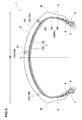
Fig. 1 is a developed partial view of the tread portion of a motorcycle tire according to the present invention. -
Fig. 2 is a cross sectional view of the motorcycle tire taken along line A1-A1 inFig. 1 . -
Fig. 3(a) is a cross sectional view taken along line A2-A2 inFig. 1 . -
Fig. 3(b) is a cross sectional view taken along line A3-A3 inFig. 1 . -
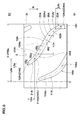
Fig. 4 is a top view of a left-hand main oblique groove. -
Fig. 5 is a top view of a right-hand main oblique groove. -
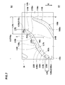
Fig. 6 is a top view of a left-hand auxiliary oblique groove. -
Fig. 7 is a top view of a right-hand auxiliary oblique groove. -
Fig. 8 shows a part of a tread pattern used in the undermentioned comparison test. - Embodiments of the present invention will now be described in detail in conjunction with the accompanying drawings.
- According to the present invention, as shown in
Fig. 1 andFig. 2 , amotorcycle tire 1 comprises atread portion 2, a pair of axially spacedbead portions 4 each with abead core 5 therein, a pair ofsidewall portions 3 extending between the tread edges and thebead portions 4, acarcass 6 extending between thebead portions 4 through thetread portion 2 andsidewall portions 3, and abelt 7 disposed radially outside thecarcass 6 in thetread portion 2. - The
tread portion 2 is convexly curved so that thetread face 2S between thetread edges 2t is curved like an arc swelling radially outwardly as a characteristic of a motorcycle tire, and the maximum cross sectional width of the tire occurs between thetread edges 2t, namely, the maximum cross sectional width of the tire equals to the axial tread width TW. - The
carcass 6 is composed of asingle ply 6A of carcass cords arranged at an angle of from 75 to 90 degrees, preferably 80 to 90 degrees with respect to the tire equator C, and extending between thebead portions 4 through thetread portion 2 andsidewall portions 3, and further turned up around thebead core 5 in each of thebead portions 4 so as to form a pair of turned upportions 6b and amain portion 6a therebetween. For the carcass cords, organic fiber cords such as nylon, polyester and rayon can be used suitably. - The
bead portions 4 are each provided between the carcass plymain portion 6a and turned upportion 6b with abead apex 8 made of hard rubber extending radially outwardly in a tapered manner from the bead core. - The
belt 7 is composed of at least one ply (in this example, twocross plies - The
tread portion 2 is provided with tread grooves defining a unidirectional tread pattern having an intended or designed rotational direction R. - As shown in
Fig. 1 , the tread grooves in this embodiment are mainoblique grooves 11 and auxiliaryoblique grooves 12. There is no groove other than theoblique grooves - The main
oblique grooves 11 are
left-hand first mainoblique grooves 11A disposed within a left half E1 of thetread portion 2 on the left side of the tire equator C, and
right-hand second mainoblique grooves 11B disposed within a right half E2 of thetread portion 2 on the right side of the tire equator C. - The left-hand main
oblique grooves 11A and the right-hand mainoblique grooves 11B are arraigned circumferentially of the tire in a staggered manner. - The configuration of the left-hand main
oblique groove 11A and the configuration of the right-hand mainoblique grooves 11B are symmetrical about the tire equator C. - Preferably, the main oblique groove 11 (11A, 11B) has a maximum groove width W1 of about 3.5 to 5.0 mm, and a maximum groove depth D1 of about 3.5 to 5.0 mm.
- The main oblique groove 11 (11A, 11B) has a
groove bottom 13 and a pair ofgroove sidewalls 14. As shown inFig. 3(a) , in a cross section perpendicular to the widthwise center line of the groove, thegroove sidewalls 14 extend from thegroove bottom 13 to thetread surface 2S, while inclining outwardly with respect to a normal line to the tread surface. - For the sake of convenience, one of the
groove sidewalls 14 to be located on the heel-side S1 (or trailing edge side) in the intended tire rotational direction is called "heel-side groove sidewall 14A", and
the other to be located on the toe-side S2 (or leading edge side) in the intended tire rotational direction is called "toe-side groove sidewall 14B". - In this embodiment, in the above-mentioned cross section, the angle β1a of the heel-
side groove sidewall 14A with respect to a normal line to the tread surface is set to be more than the angle β1b of the toe-side groove sidewall 14B with respect to a normal line to the tread surface. Preferably, the angle β1a of the heel-side groove sidewall 14A is 5 to 30 degrees, and the angle β1b of the toe-side groove sidewall 14B is 0 to 5 degrees. - By configuring the
main oblique grooves main oblique grooves 11, and accordingly to increase the circumferential rigidity of such tread elements. Therefore, it becomes possible to improve the high-speed stability. - The axially inner end 11Ai of the left-hand
main oblique groove 11A is positioned at an axial distance L1a of from 1 to 4 mm from the tire equator C not to extend beyond the tire equator C from E1 side to E2 side as shown inFig. 1 .
The axially inner end 11Bi of the right-handmain oblique groove 11B is positioned at an axial distance L1b of from 1 to 4 mm from the tire equator C not to extend beyond the tire equator C from E2 side to E1 side.
Preferably, the distances L1a and L1b are not less than 1.5 mm, and not more than 3.5 mm. - Such
main oblique grooves tread portion 2 in the vicinity of the tire equator C, and thereby the high-speed stability can be improved. - If the distance (L1a, L1b) is less than 1 mm, then it becomes difficult to improve the high-speed stability. If the distance (L1a, L1b) is more than 4 mm, then the drainage is decreased near the tire equator C and there is a possibility that the wet performance during straight running deteriorates.
- In this application, the axially inner end and the axially outer end of a groove or a part of a groove refer to those of the widthwise center line of the groove.
- As shown in
Fig. 4 andFig. 5 , the main oblique groove 11 (11A, 11B) has a substantially S-shaped configuration and is made up of
an axially inner part (15A, 15B) extending axially outwardly from the above-mentioned inner end (11Ai, 11Bi) and inclining at an angle α1a of not more than 30 degrees with respect to the tire circumferential direction,
a middle part (16A, 16B) connected to the axially inner part (15A, 15B) through an inside curved part ((18A, 18B)) and extending at an angle α1b of from 25 to 70 degrees with respect to the tire circumferential direction which is more than angle α1a, and
an axially outer part (17A, 17B) connected to the middle part (16A, 16B) through an outside curved part (19A, 19B) and extending at an angle α1c of not more than 30 degrees with respect to the tire circumferential direction which is less than angle α1b. - Here, the angle (α1a, α1b and α1c) means the angle of the widthwise center line (11Ac, 11Bc) of the main oblique groove (11A, 11B).
- As the axially inner part (15A, 15B) extends at a relatively small angle α1a near the tire equator, sufficient drainage is provided in the vicinity of the tire equator without forming a circumferential groove. Further, by the S-shaped configuration including the curved parts (18A, 18B, 19A, 19B), water existing in the tread center region is effectively led to the tread edges and discharged. Furthermore, the change in the tread pattern rigidity in the tire axial direction becomes smooth and the handling stability can be improved. Further, tread pattern noise can be improved.
- The axially inner part (15A, 15B) extends straight from its axially inner end (15Ai, 15Bi) to outer end (15Ao, 15Bo), while inclining to the rotational direction R at the angle α1a ( <= 30 degrees). Preferably, the angle α1a is not more than 25 degrees and not less than 10 degrees.
Further, the groove width W1 of the axially inner part is gradually decreased from the outer end (15Ao, 15Bo) to the inner end (15Ai, 15Bi) not to decrease the rigidity in the vicinity of the tire equator C as far as possible and so that the change in the tread pattern rigidity form the tire equator C to the outer end (15Ao, 15Bo) becomes smooth and the handling stability can be improved. If the angle α1a of the axially inner part (15A, 15B) is more than 30 degrees, it becomes difficult to obtain such advantageous effects. - The circumferential distance (L2a, L2b) between the axially inner end (15Ai, 15Bi) and outer end (15Ao, 15Bo) of the axially inner part (15A, 15B) is preferably not less than 15 mm, more preferably not less than 17 mm, but not more than 25 mm, more preferably not more than 23 mm.
- The middle part (16A, 16B) extends straight from its axially inner end (16Ai, 16Bi) to outer end (16Ao, 16Bo), while inclining to the rotational direction R at the angle α1b (25 to 70 degrees). Preferably, the angle α1b is not less than 35 degrees and not more than 65 degrees.
- If the angle α1b of the middle part (16A, 16B) is less than 25 degrees, handling and stability during cornering are liable to deteriorate. If the angle α1b is more than 70 degrees, the drainage performance is deteriorated and the tread pattern noise increases.
- The axial distance (L3a, L3b) between the axially inner end (16Ai, 16Bi) and outer end (16Ao, 16Bo) of the middle part (16A, 16B) is preferably set in a range of not less than 50 mm, more preferably not less than 53 mm, but not more than 65 mm, more preferably not more than 62 mm.
- The axially outer part (17A, 17B) extends straight from its axially inner end (17Ai, 17Bi) to outer end (17Ao, 17Bo), while inclining to the rotational direction R at the angle α1c (not more than 30 degrees). Preferably, the angle α1c not more than 25 degrees and not less than 10 degrees.
- The groove width W1 of the axially outer part (17A, 17B) is gradually decreased from the inner end (17Ai, 17Bi) to the outer end (17Ao, 17Bo) not to decrease the tread pattern rigidity near the
tread edge 2t and so that the handling stability can be improved. - As the axially outer parts (17A, 17B) extend at a relatively small angle α1c near the tread edges 2t, it is possible to improve the drainage and pattern noise during cornering. If the angle α1c of the axially outer part (17A, 17B) exceeds 30 degrees, it becomes difficult to obtain such advantageous effects.
- The circumferential distance (L4a, L4b) between the inner end (17Ai, 17Bi) and outer end (17Ao, 17Bo) of the axially outer part (17A, 17B) is preferably set in a range of not less than 8 mm, more preferably not less than 10 mm, but not more than 16 mm, more preferably not more than 14 mm.
- The inside curved part (18A, 18B) smoothly connects between the axially inner part (15A, 15B) and the middle part (16A, 16B), describing an arc convex toward the heel-side S1. Preferably, the radius of curvature R1a of the widthwise center line of the inside curved part (18A, 18B) is set in a range of not less than 15 mm, more preferably not less than 20 mm, but not more than 30 mm, more preferably not more than 25 mm in view of the drainage, pattern rigidity change, handling stability and noise performance.
- The outside curved part (19A, 19B) smoothly connects between the middle part (16A, 16B) and the axially outer part (17A, 17B), describing an arc convex toward the toe-side S2. Preferably, the radius of curvature R1b of the widthwise center line of the outside curved part (19A, 19B) is set in a range of not less than 15 mm, more preferably not less than 20 mm, but not more than 30 mm, more preferably not more than 25 mm in view of the drainage, handling stability and noise performance.
- The above-mentioned
auxiliary oblique grooves 12 are left-handauxiliary oblique grooves 12A arranged alternately with the left-handmain oblique grooves 11A, and right-handauxiliary oblique grooves 12B arranged alternately with the right-hand mainoblique grooves 11B. - The left-hand
auxiliary oblique groove 12A has its axially inner end 12Ai and outer end 12Ao within the left half E1 of thetread portion 2 and is inclined to the same direction as the left-handmain oblique grooves 11A.
The right-handauxiliary oblique groove 12B has its axially inner end 12Bi and outer end 12Bo within the right half E2 of thetread portion 2 and is inclined to the same direction as the right-hand mainoblique grooves 11B.
Preferably, theauxiliary oblique groove 12 has
a maximum groove width W2 of from about 3.5 to 5.0 mm, and a maximum groove depth D2 of from about 3.5 to 5.0 mm to enhance the drainage in cooperation with themain oblique grooves - The auxiliary oblique groove (12A, 12B) has a groove bottom 27 and a pair of
groove sidewalls 28. As show inFig. 3(b) , in a cross section perpendicular to the widthwise center line of the groove, the groove sidewalls 28 extend from the groove bottom 27 to thetread surface 2S, while inclining outwardly with respect to a normal line to the tread surface. For the sake of convenience, one of the groove sidewalls 28 to be located on the heel-side S1 in the intended tire rotational direction is called "heel-side groove sidewall 28A", and the other to be located on the toe-side S2 in the intended tire rotational direction is called "toe-side groove sidewall 28B". - In this embodiment, in the cross section perpendicular to the widthwise center line, the angle β2a of the heel-
side groove sidewall 28A with respect to a normal line to the tread surface is set to be more than the angle β2b of the toe-side groove sidewall 28B with respect to a normal line to the tread surface. Preferably, the angle β2a of the heel-side groove sidewall 28A is set in a range of from 5 to 30 degrees, and the angle β2b of the toe-side groove sidewall 28B is set in a range of from 0 to 5 degrees. - By configuring the
auxiliary oblique grooves - On each side of the tire equator C, the axially inner end (12Ai, 12Bi) of the auxiliary oblique groove (12A, 12B) is positioned axially outside the inside curved part (18A, 18B) of the main oblique groove (11A, 11B).
- As shown in
Figs. 6 and7 , the axial distance (L5a, L5b) between the axially inner end (12Ai, 12Bi) and the inside curved part (18A, 18B) is preferably set in a range of not less than 4 mm, more preferably not less than 5 mm, but not more than 9 mm, more preferably not more than 8 mm. - If the distances L5a and L5b are more than 8mm, there is a possibility that the drainage becomes insufficient. If the axial distances L5a and L5b are less than 4 mm, there is a possibility that the circumferential rigidity of the
tread portion 2 near the tire equator C decreases and it becomes difficult to improve the high-speed stability. - Further, on each side of the tire equator C, the axially outer ends (12Ao, 12Bo) of the auxiliary oblique grooves (12A, 12B) are positioned at the same axial position as the axially outer ends (11Ao, 11Bo) of the main oblique grooves (11A, 11B) as shown in
Fig. 1 in order to improve the drainage during cornering. - The auxiliary oblique groove (12A, 12B) has a substantially S-shaped configuration similar to that of the circumferentially adjacent main oblique groove (11A, 11B) and is made up of
an axially inner part (21A, 21B) extending axially outwardly from the above-mentioned axially inner end (12Ai, 12Bi) at an angle α2a of from 25 to 55 degrees with respect to the tire circumferential direction,
a middle part (22A, 22B) connected to the axially inner part (21A, 21B) through an inside curved part (24A, 24B) and extending axially outwardly at an angle α2b of from 45 to 75 degrees with respect to the tire circumferential direction which is more than the angle α2a, and
an axially outer part (23A, 23B) connected to the middle part (22A, 22B) through an outside curved part (25A, 25B) and extending at an angle α2c of not more than 30 degrees with respect to the tire circumferential direction which is less than the an angle α2b. - As shown in
Fig. 6 andFig. 7 , the axially inner part (21A, 21B) extends straight from its axially inner end (21Ai, 21Bi) to outer end (21Ao, 21Bo), while inclining to the intended tire rotational direction R at the angle α2a (25 to 55 degrees) more than the angle α1a of the axially inner part (15A, 15B) of the main oblique groove (11A, 11B). Preferably, the angle α2a is not more than 50 degrees and not less than 30 degrees. - The groove width W2 of the inner part (21A, 21B) is gradually decreased from the inner end (21Ai, 21Bi) to the outer end (21Ao, 21Bo).
- By such S-shaped configuration, water existing in the tread middle region is effectively led to the tread edges and discharged. Furthermore, the change in the tread pattern rigidity in the tire axial direction becomes smooth and the handling stability can be improved. Further, tread pattern noise can be improved. These advantageous effects become difficult to obtain if the angle α2a is more than 55 degrees. If the angle α2a is less than 25 degrees, the handling stability is liable to deteriorate.
- The circumferential distance (L6a, L6b) between the axially inner end (21Ai, 21Bi) and outer end (21Ao, 21Bo) of the axially inner part (21A, 21B) is preferably set in a range of not less than 8 mm, more preferably not less than 10 mm, but not more than 15 mm, more preferably not more than 13 mm.
- The middle part (22A, 22B) extends straight from its axially inner end (22Ai, 22Bi) to outer end (22Ao, 22Bo), while inclining to the intended tire rotational direction R at the angle α2b (45 to 75 degrees). Preferably, the angle α2b is not less than 50 degrees and not more than 70 degrees to improve the handling and stability during cornering.
- If the angle α2b of the middle part (22A, 22B) is less than 45 degrees, the drainage performance and handling stability during cornering tend to deteriorate. If the angle α2b exceeds 75 degrees, the noise performance and drainage performance tend to deteriorate.
- The axial distance (L7a, L7b) between the axially inner end (22Ai, 22Bi) and outer end (22Ao, 22Bo) of the middle part (22A, 22B) is preferably set in a range of not less than 25 mm, more preferably not less than 27 mm, but not more than 35 mm, more preferably not more than 33 mm.
- The axially outer part (23A, 23B) extends straight from its axially inner end (23Ai, 23Bi) to outer end (23Ao, 23Ao), while inclining to the intended tire rotational direction R at the angle α2c (not more than 30 degrees). Preferably, the angle α2c is not more than 25 degrees and not less than 10 degrees in order to enhance the drainage during cornering near the
tread edge 2t. - The groove width W2 of the outer part (23A, 23B) is gradually decreased from the outer end (23Ao, 23Ao) to the inner end (23Ai, 23Bi) to minimize the decrease in the tread pattern rigidity near the
tread edge 2t and so that the handling stability can be improved. - The circumferential distance (L8a, L8b) between the axially inner end (23Ai, 23Bi) and outer end (23Ao, 23Bo) of the axially outer part (23A, 23B) is preferably set in a range of not less than 8 mm, more preferably not less than 10 mm, but not more than 16 mm, more preferably not more than 14 mm.
- The inside curved part (24A, 24B) smoothly connects between the axially inner part (21A, 21B) and the middle part (22A, 22B), describing an arc convex toward the heel-side S1. The radius of curvature R2a of the widthwise center line of the inside curved part (24A, 24B) is preferably set in a range of not less than 15 mm, more preferably not less than 20 mm, but not more than 50 mm, more preferably not more than 30 mm in view of the noise performance, drainage and handling stability.
- The axial distance (L9a, L9b) between the axially inner end (24Ai, 24Bi) of the inside curved part (24A, 24B) and the tire equator C is set in a range of not less than 30 %, preferably not less than 35 % but not more than 55 %, preferably not more than 45 % of one half of the developed tread width measured axially between the tread edges 2t along the
tread surface 2S in order to reduce the pattern noise during straight running. - If the distances L9a and L9b are less than 30 % of a half developed tread width TWe, it is difficult to expect the reduction of the pattern noise during straight running. If the distances L9a and L9b are more than 50 % a half developed tread width TWe, the tread pattern rigidity increases in the tread central region and middle region, ride comfort tends to deteriorate.
- The outside curved part (25A, 25B) smoothly connects between the middle part (22A, 22B) and the axially outer part (23A, 23B), describing an arc convex toward the toe-side S2. The radius of curvature R2b of the widthwise center line of the outside curved part (25A, 25B) is preferably set in a range of not less than 15 mm, more preferably not less than 20 mm, but not more than 50 mm, more preferably not more than 30 mm in view of the noise performance, drainage and handling stability.
- Test tires having the internal tire structure shown in
Fig. 2 and main oblique grooves and auxiliary oblique grooves shown in Table 1 were prepared and tested.
Common specifications are as follows.
Tire size: 90/90-21 M/C 54H (rim size: 21XMT2.15)
Axial tread width TW: 91 mm
Half developed tread width TWe: 52 mm
Main oblique grooves: - maximum groove width W1: 5.0 mm
- maximum groove depth D1: 4.5 mm
- angle β1a of heel-side groove sidewall:15 degrees
- angle β1b of toe-side groove sidewall: 5 degrees
- distance L2a, L2b between inner and outer ends of inner part: 13 mm
- distance L3a, L3b between inner and outer ends of middle part: 30 mm
- distance L4a, L4b between inner and outer ends of outer part: 11 mm
- maximum groove width W2: 5.0 mm
- maximum groove depth D2: 4.5 mm
- angle β2a of heel-side groove sidewall: 15 degrees
- angle β2b of toe-side groove sidewall: 5 degrees
- distance L6a, L6b between inner and outer ends of inner part: 12.5 mm
- distance L7a, L7b between inner and outer ends of middle part: 22 mm
- distance L8a, L8b between inner and outer ends of outer part: 6 mm
- The test tire was attached to a 1300 cc motorcycle. (tire pressure: 225 kPa)
- During running on a dry asphalt road in a tire test circuit course, a test rider evaluated the handling response, rigidity feeling, road grip, and high-speed stability.
- Further, during running on the wet asphalt road in the tire test circuit course, the test rider evaluated the wet road grip performance.
- According to the "Test Procedure for Tire Noise" specified in Japanese JASO-C606, the motorcycle was coasted for 50 meter distance at a speed of 60 km/h on a dry asphalt road in a straight test course, and the maximum noise sound level was measured with a microphone set at 1.2 meter height from the road surface and 7.5 meter sideways from the running center line in the midpoint of the course.
- The test results are indicated in Table 1 by an index based on comparative example tire Ref.1 being 100, wherein the larger the value, the better the performance.
- From the test results, it was confirmed that the motorcycle tires according to the present invention can be improved in the high-speed stability and noise performance.
Table 1 Tire Ref.1 Ref.2 Ex.1 Ex.2 Ex.3 Ex.4 Ex.5 Ex.6 Ex.7 Ex.8 Ex.9 Ex.10 Ex.11 tread pattern (Fig. no.) 8 1 1 1 1 1 1 1 1 1 1 1 1 main oblique grooves distance L1a, L1b(mm) - 0.0 2.5 1.0 4.0 2.5 2.5 2.5 2.5 2.5 2.5 2.5 2.5 angle α1a (deg.) - 20 20 20 20 30 10 20 20 20 20 20 20 angle α1b (deg.) - 60 60 60 60 70 25 60 60 60 60 60 60 angle α1c (deg.) - 20 20 20 20 30 10 20 20 20 20 20 20 radius R1a (mm) - 30 30 30 30 30 30 20 50 30 30 30 30 radius R1b (mm) - 30 30 30 30 30 30 20 50 30 30 30 30 auxiliary oblique grooves angle α2a (deg.) - 40 40 40 40 55 25 40 40 40 40 40 40 angle α2b (deg.) - 60 60 60 60 75 45 60 60 60 60 60 60 angle α2c (deg.) - 20 20 20 20 30 10 20 20 20 20 20 20 radius R2a (mm) - 30 30 30 30 30 30 20 50 30 30 30 30 radius R2b (mm) - 30 30 30 30 30 30 20 50 30 30 30 30 distance L5a, L5b (mm) - 5 5 5 5 5 5 5 5 1 10 5 5 distance L9a, L9b (mm) - 16 16 16 16 16 16 16 16 16 16 15.6 26 (L9a,L9b)/TWe (%) *1 - 31 31 31 31 31 31 31 31 31 31 30 50 handling stability 100 110 110 110 110 105 90 105 110 110 110 110 105 high-speed stability 100 90 110 98 115 110 110 110 110 100 110 100 110 drainage 100 110 110 110 100 105 115 105 110 110 100 115 98 noise performance 100 110 110 110 110 110 110 110 100 110 110 100 110 *1) TWe: one half of the developed tread width (=52 mm)
Claims (6)
- A motorcycle tire comprising
a tread portion whose half region on each side of the tire equator is provided with main oblique grooves and auxiliary oblique grooves each not to protrude from the one half region to the other one half region,
the main oblique grooves on both sides of the tire equator are arranged circumferentially of the tire in a staggered manner,
each of the auxiliary oblique grooves is disposed between the circumferentially adjacent main oblique grooves so as to incline in the same direction as the main oblique grooves,
the axially inner end of each of the main oblique grooves is positioned at a first axial distance of 1 to 4 mm from the tire equator,
the axially inner end of each of the auxiliary oblique grooves is positioned at a second axial distance from the tire equator which is more than the first axial distance,
each of the main oblique grooves comprises an axially inner part, a middle part and an axially outer part, wherein the axially inner part extends axially outwardly from the axially inner end of the main oblique groove, while inclining at an angle of not more than 30 degrees with respect to the tire circumferential direction, and the middle part is connected to the axially inner part through a curved part and extends at an angle with respect to the tire circumferential direction, which angle is more than the angle of the axially inner part and in a range of from 25 to 70 degrees, and
each of the auxiliary oblique grooves comprises an axially inner part, a middle part and an axially outer part, wherein the axially inner part extends axially outwardly from the axially inner end of the auxiliary oblique grooves, while inclining at an angle of 25 to 55 degrees with respect to the tire circumferential direction, and the middle part is connected to the axially inner part through a curved part and extends at an angle with respect to the tire circumferential direction, which angle is more than the angle of the axially inner part and in a range of from 45 to 75 degrees. - The motorcycle tire according to claim 1, wherein
the axially inner end of the auxiliary oblique groove is positioned axially outside said curved part of the main oblique groove. - The motorcycle tire according to claim 1 or 2, wherein
the angle of the inner part of the auxiliary oblique groove is more than the angle of the inner part of the main oblique groove. - The motorcycle tire according to any one of claims 1-3, wherein
the axial distance from the tire equator to the axially inner end of the curved part connecting between the axially inner part and the middle part of the auxiliary oblique groove is 30 to 55 % of one half of the developed tread width. - The motorcycle tire according to any one of claims 1-4, wherein
the axially outer end of the main oblique groove and the axially outer end of the auxiliary oblique groove are positioned at the same axial distance from the tire equator. - The motorcycle tire according to claim 1, wherein
said axially outer part of the main oblique groove inclines at an angle less than the angle of the middle part with respect to the tire circumferential direction, and
said axially outer part of the auxiliary oblique groove inclines at an angle less than the angle of the middle part with respect to the tire circumferential direction.
Applications Claiming Priority (1)
| Application Number | Priority Date | Filing Date | Title |
|---|---|---|---|
| JP2011083859A JP5261530B2 (en) | 2011-04-05 | 2011-04-05 | Motorcycle tires |
Publications (2)
| Publication Number | Publication Date |
|---|---|
| EP2508362A1 true EP2508362A1 (en) | 2012-10-10 |
| EP2508362B1 EP2508362B1 (en) | 2018-12-12 |
Family
ID=45936949
Family Applications (1)
| Application Number | Title | Priority Date | Filing Date |
|---|---|---|---|
| EP12161645.2A Active EP2508362B1 (en) | 2011-04-05 | 2012-03-28 | Motorcycle tire |
Country Status (5)
| Country | Link |
|---|---|
| US (1) | US9227468B2 (en) |
| EP (1) | EP2508362B1 (en) |
| JP (1) | JP5261530B2 (en) |
| CN (1) | CN102729738B (en) |
| TW (1) | TWI486266B (en) |
Families Citing this family (7)
| Publication number | Priority date | Publication date | Assignee | Title |
|---|---|---|---|---|
| USD745423S1 (en) | 2014-05-12 | 2015-12-15 | Cue Inc. | Automated analyzer test cartridge and sample collection device for analyte detection |
| CN104029568A (en) * | 2014-06-11 | 2014-09-10 | 厦门正新橡胶工业有限公司 | Tire tread structure of pneumatic tire of motorcycle |
| JP6850695B2 (en) * | 2017-07-14 | 2021-03-31 | 株式会社ブリヂストン | Pneumatic tires for motorcycles |
| TWI690434B (en) * | 2019-04-12 | 2020-04-11 | 正新橡膠工業股份有限公司 | Tire with enhanced drainage ability |
| TWI797460B (en) * | 2020-07-06 | 2023-04-01 | 固滿德工業股份有限公司 | Rubber composition and manufacturing method and energy saving tire thereof |
| JP7651922B2 (en) * | 2021-04-08 | 2025-03-27 | 住友ゴム工業株式会社 | Motorcycle tires |
| JP7841298B2 (en) * | 2022-03-15 | 2026-04-07 | 住友ゴム工業株式会社 | Motorcycle tires |
Citations (4)
| Publication number | Priority date | Publication date | Assignee | Title |
|---|---|---|---|---|
| JPH11291716A (en) | 1998-04-13 | 1999-10-26 | Sumitomo Rubber Ind Ltd | Motorcycle tires |
| WO2007023895A1 (en) * | 2005-08-25 | 2007-03-01 | Bridgestone Corporation | Pneumatic tire for bicycle |
| EP1884377A1 (en) * | 2005-05-17 | 2008-02-06 | Bridgestone Corporation | Pneumatic radial tire for motorcycle |
| WO2011118186A1 (en) * | 2010-03-26 | 2011-09-29 | 株式会社ブリヂストン | Pneumatic tire for motorcycle |
Family Cites Families (9)
| Publication number | Priority date | Publication date | Assignee | Title |
|---|---|---|---|---|
| JPH05201207A (en) * | 1992-01-27 | 1993-08-10 | Bridgestone Corp | Pneumatic tire for motorcycle |
| EP0816130B1 (en) * | 1996-06-28 | 2005-02-09 | Sumitomo Rubber Industries Limited | Pneumatic tyre |
| JP3495593B2 (en) * | 1998-04-07 | 2004-02-09 | 住友ゴム工業株式会社 | Motorcycle front wheel tires |
| JP5013759B2 (en) * | 2006-06-15 | 2012-08-29 | 株式会社ブリヂストン | Motorcycle tires |
| BRPI0722196C8 (en) * | 2007-11-06 | 2019-08-13 | Pirelli | motorcycle tire and motorcycle |
| JP4572977B2 (en) * | 2008-09-29 | 2010-11-04 | 横浜ゴム株式会社 | Pneumatic tire |
| USD600631S1 (en) * | 2008-10-08 | 2009-09-22 | The Goodyear Tire & Rubber Company | Tire for motorcycle |
| JP5351627B2 (en) * | 2009-06-12 | 2013-11-27 | 住友ゴム工業株式会社 | Motorcycle tires |
| WO2011012979A1 (en) * | 2009-07-28 | 2011-02-03 | Pirelli Tyre S.P.A. | Motor vehicle tyre |
-
2011
- 2011-04-05 JP JP2011083859A patent/JP5261530B2/en not_active Expired - Fee Related
-
2012
- 2012-03-28 EP EP12161645.2A patent/EP2508362B1/en active Active
- 2012-03-30 CN CN201210091350.4A patent/CN102729738B/en active Active
- 2012-04-03 TW TW101111854A patent/TWI486266B/en not_active IP Right Cessation
- 2012-04-04 US US13/438,938 patent/US9227468B2/en active Active
Patent Citations (4)
| Publication number | Priority date | Publication date | Assignee | Title |
|---|---|---|---|---|
| JPH11291716A (en) | 1998-04-13 | 1999-10-26 | Sumitomo Rubber Ind Ltd | Motorcycle tires |
| EP1884377A1 (en) * | 2005-05-17 | 2008-02-06 | Bridgestone Corporation | Pneumatic radial tire for motorcycle |
| WO2007023895A1 (en) * | 2005-08-25 | 2007-03-01 | Bridgestone Corporation | Pneumatic tire for bicycle |
| WO2011118186A1 (en) * | 2010-03-26 | 2011-09-29 | 株式会社ブリヂストン | Pneumatic tire for motorcycle |
Also Published As
| Publication number | Publication date |
|---|---|
| TW201240844A (en) | 2012-10-16 |
| US20120255660A1 (en) | 2012-10-11 |
| EP2508362B1 (en) | 2018-12-12 |
| JP5261530B2 (en) | 2013-08-14 |
| CN102729738B (en) | 2015-12-02 |
| JP2012218495A (en) | 2012-11-12 |
| CN102729738A (en) | 2012-10-17 |
| US9227468B2 (en) | 2016-01-05 |
| TWI486266B (en) | 2015-06-01 |
Similar Documents
| Publication | Publication Date | Title |
|---|---|---|
| EP2492116B1 (en) | Motorcycle tire | |
| US9457622B2 (en) | Pneumatic tire | |
| EP2716477B1 (en) | Pneumatic tire | |
| US9815336B2 (en) | Pneumatic tire | |
| US9162531B2 (en) | Motorcycle tire | |
| US9688103B2 (en) | Motorcycle tire | |
| US10173473B2 (en) | Pneumatic motorcycle tire | |
| EP2508362B1 (en) | Motorcycle tire | |
| US20130112325A1 (en) | Pneumatic tire | |
| EP2752310A1 (en) | Motorcycle tire | |
| US20120312437A1 (en) | Motorcycle tire | |
| EP3050720B1 (en) | Pneumatic motorcycle tire | |
| JP6375851B2 (en) | Pneumatic tire | |
| US20120037287A1 (en) | Heavy duty pneumatic tire | |
| JP6375850B2 (en) | Pneumatic tire | |
| US20130206300A1 (en) | Motorcycle tire | |
| EP2639083B1 (en) | Motorcycle tire | |
| US20120060990A1 (en) | Pneumatic tire | |
| US9956824B2 (en) | Motorcycle tire | |
| EP3199374B1 (en) | Motorcycle tire |
Legal Events
| Date | Code | Title | Description |
|---|---|---|---|
| PUAI | Public reference made under article 153(3) epc to a published international application that has entered the european phase |
Free format text: ORIGINAL CODE: 0009012 |
|
| AK | Designated contracting states |
Kind code of ref document: A1 Designated state(s): AL AT BE BG CH CY CZ DE DK EE ES FI FR GB GR HR HU IE IS IT LI LT LU LV MC MK MT NL NO PL PT RO RS SE SI SK SM TR |
|
| AX | Request for extension of the european patent |
Extension state: BA ME |
|
| 17P | Request for examination filed |
Effective date: 20130325 |
|
| 17Q | First examination report despatched |
Effective date: 20130508 |
|
| STAA | Information on the status of an ep patent application or granted ep patent |
Free format text: STATUS: EXAMINATION IS IN PROGRESS |
|
| REG | Reference to a national code |
Ref country code: DE Ref legal event code: R079 Ref document number: 602012054558 Country of ref document: DE Free format text: PREVIOUS MAIN CLASS: B60C0011030000 Ipc: B60C0011130000 |
|
| RIC1 | Information provided on ipc code assigned before grant |
Ipc: B60C 11/13 20060101AFI20180713BHEP Ipc: B60C 11/03 20060101ALI20180713BHEP |
|
| GRAP | Despatch of communication of intention to grant a patent |
Free format text: ORIGINAL CODE: EPIDOSNIGR1 |
|
| STAA | Information on the status of an ep patent application or granted ep patent |
Free format text: STATUS: GRANT OF PATENT IS INTENDED |
|
| INTG | Intention to grant announced |
Effective date: 20180925 |
|
| GRAS | Grant fee paid |
Free format text: ORIGINAL CODE: EPIDOSNIGR3 |
|
| GRAA | (expected) grant |
Free format text: ORIGINAL CODE: 0009210 |
|
| STAA | Information on the status of an ep patent application or granted ep patent |
Free format text: STATUS: THE PATENT HAS BEEN GRANTED |
|
| AK | Designated contracting states |
Kind code of ref document: B1 Designated state(s): AL AT BE BG CH CY CZ DE DK EE ES FI FR GB GR HR HU IE IS IT LI LT LU LV MC MK MT NL NO PL PT RO RS SE SI SK SM TR |
|
| REG | Reference to a national code |
Ref country code: GB Ref legal event code: FG4D |
|
| REG | Reference to a national code |
Ref country code: CH Ref legal event code: EP |
|
| REG | Reference to a national code |
Ref country code: AT Ref legal event code: REF Ref document number: 1075448 Country of ref document: AT Kind code of ref document: T Effective date: 20181215 |
|
| REG | Reference to a national code |
Ref country code: DE Ref legal event code: R096 Ref document number: 602012054558 Country of ref document: DE |
|
| REG | Reference to a national code |
Ref country code: IE Ref legal event code: FG4D |
|
| REG | Reference to a national code |
Ref country code: NL Ref legal event code: MP Effective date: 20181212 |
|
| REG | Reference to a national code |
Ref country code: LT Ref legal event code: MG4D |
|
| PG25 | Lapsed in a contracting state [announced via postgrant information from national office to epo] |
Ref country code: LV Free format text: LAPSE BECAUSE OF FAILURE TO SUBMIT A TRANSLATION OF THE DESCRIPTION OR TO PAY THE FEE WITHIN THE PRESCRIBED TIME-LIMIT Effective date: 20181212 Ref country code: ES Free format text: LAPSE BECAUSE OF FAILURE TO SUBMIT A TRANSLATION OF THE DESCRIPTION OR TO PAY THE FEE WITHIN THE PRESCRIBED TIME-LIMIT Effective date: 20181212 Ref country code: LT Free format text: LAPSE BECAUSE OF FAILURE TO SUBMIT A TRANSLATION OF THE DESCRIPTION OR TO PAY THE FEE WITHIN THE PRESCRIBED TIME-LIMIT Effective date: 20181212 Ref country code: NO Free format text: LAPSE BECAUSE OF FAILURE TO SUBMIT A TRANSLATION OF THE DESCRIPTION OR TO PAY THE FEE WITHIN THE PRESCRIBED TIME-LIMIT Effective date: 20190312 Ref country code: FI Free format text: LAPSE BECAUSE OF FAILURE TO SUBMIT A TRANSLATION OF THE DESCRIPTION OR TO PAY THE FEE WITHIN THE PRESCRIBED TIME-LIMIT Effective date: 20181212 Ref country code: BG Free format text: LAPSE BECAUSE OF FAILURE TO SUBMIT A TRANSLATION OF THE DESCRIPTION OR TO PAY THE FEE WITHIN THE PRESCRIBED TIME-LIMIT Effective date: 20190312 Ref country code: HR Free format text: LAPSE BECAUSE OF FAILURE TO SUBMIT A TRANSLATION OF THE DESCRIPTION OR TO PAY THE FEE WITHIN THE PRESCRIBED TIME-LIMIT Effective date: 20181212 |
|
| REG | Reference to a national code |
Ref country code: AT Ref legal event code: MK05 Ref document number: 1075448 Country of ref document: AT Kind code of ref document: T Effective date: 20181212 |
|
| PG25 | Lapsed in a contracting state [announced via postgrant information from national office to epo] |
Ref country code: RS Free format text: LAPSE BECAUSE OF FAILURE TO SUBMIT A TRANSLATION OF THE DESCRIPTION OR TO PAY THE FEE WITHIN THE PRESCRIBED TIME-LIMIT Effective date: 20181212 Ref country code: SE Free format text: LAPSE BECAUSE OF FAILURE TO SUBMIT A TRANSLATION OF THE DESCRIPTION OR TO PAY THE FEE WITHIN THE PRESCRIBED TIME-LIMIT Effective date: 20181212 Ref country code: AL Free format text: LAPSE BECAUSE OF FAILURE TO SUBMIT A TRANSLATION OF THE DESCRIPTION OR TO PAY THE FEE WITHIN THE PRESCRIBED TIME-LIMIT Effective date: 20181212 Ref country code: GR Free format text: LAPSE BECAUSE OF FAILURE TO SUBMIT A TRANSLATION OF THE DESCRIPTION OR TO PAY THE FEE WITHIN THE PRESCRIBED TIME-LIMIT Effective date: 20190313 |
|
| PG25 | Lapsed in a contracting state [announced via postgrant information from national office to epo] |
Ref country code: NL Free format text: LAPSE BECAUSE OF FAILURE TO SUBMIT A TRANSLATION OF THE DESCRIPTION OR TO PAY THE FEE WITHIN THE PRESCRIBED TIME-LIMIT Effective date: 20181212 |
|
| PG25 | Lapsed in a contracting state [announced via postgrant information from national office to epo] |
Ref country code: PL Free format text: LAPSE BECAUSE OF FAILURE TO SUBMIT A TRANSLATION OF THE DESCRIPTION OR TO PAY THE FEE WITHIN THE PRESCRIBED TIME-LIMIT Effective date: 20181212 Ref country code: CZ Free format text: LAPSE BECAUSE OF FAILURE TO SUBMIT A TRANSLATION OF THE DESCRIPTION OR TO PAY THE FEE WITHIN THE PRESCRIBED TIME-LIMIT Effective date: 20181212 Ref country code: IT Free format text: LAPSE BECAUSE OF FAILURE TO SUBMIT A TRANSLATION OF THE DESCRIPTION OR TO PAY THE FEE WITHIN THE PRESCRIBED TIME-LIMIT Effective date: 20181212 Ref country code: PT Free format text: LAPSE BECAUSE OF FAILURE TO SUBMIT A TRANSLATION OF THE DESCRIPTION OR TO PAY THE FEE WITHIN THE PRESCRIBED TIME-LIMIT Effective date: 20190412 |
|
| PG25 | Lapsed in a contracting state [announced via postgrant information from national office to epo] |
Ref country code: IS Free format text: LAPSE BECAUSE OF FAILURE TO SUBMIT A TRANSLATION OF THE DESCRIPTION OR TO PAY THE FEE WITHIN THE PRESCRIBED TIME-LIMIT Effective date: 20190412 Ref country code: RO Free format text: LAPSE BECAUSE OF FAILURE TO SUBMIT A TRANSLATION OF THE DESCRIPTION OR TO PAY THE FEE WITHIN THE PRESCRIBED TIME-LIMIT Effective date: 20181212 Ref country code: EE Free format text: LAPSE BECAUSE OF FAILURE TO SUBMIT A TRANSLATION OF THE DESCRIPTION OR TO PAY THE FEE WITHIN THE PRESCRIBED TIME-LIMIT Effective date: 20181212 Ref country code: SM Free format text: LAPSE BECAUSE OF FAILURE TO SUBMIT A TRANSLATION OF THE DESCRIPTION OR TO PAY THE FEE WITHIN THE PRESCRIBED TIME-LIMIT Effective date: 20181212 Ref country code: SK Free format text: LAPSE BECAUSE OF FAILURE TO SUBMIT A TRANSLATION OF THE DESCRIPTION OR TO PAY THE FEE WITHIN THE PRESCRIBED TIME-LIMIT Effective date: 20181212 |
|
| REG | Reference to a national code |
Ref country code: DE Ref legal event code: R097 Ref document number: 602012054558 Country of ref document: DE |
|
| PLBE | No opposition filed within time limit |
Free format text: ORIGINAL CODE: 0009261 |
|
| STAA | Information on the status of an ep patent application or granted ep patent |
Free format text: STATUS: NO OPPOSITION FILED WITHIN TIME LIMIT |
|
| PG25 | Lapsed in a contracting state [announced via postgrant information from national office to epo] |
Ref country code: MC Free format text: LAPSE BECAUSE OF FAILURE TO SUBMIT A TRANSLATION OF THE DESCRIPTION OR TO PAY THE FEE WITHIN THE PRESCRIBED TIME-LIMIT Effective date: 20181212 Ref country code: AT Free format text: LAPSE BECAUSE OF FAILURE TO SUBMIT A TRANSLATION OF THE DESCRIPTION OR TO PAY THE FEE WITHIN THE PRESCRIBED TIME-LIMIT Effective date: 20181212 Ref country code: DK Free format text: LAPSE BECAUSE OF FAILURE TO SUBMIT A TRANSLATION OF THE DESCRIPTION OR TO PAY THE FEE WITHIN THE PRESCRIBED TIME-LIMIT Effective date: 20181212 Ref country code: SI Free format text: LAPSE BECAUSE OF FAILURE TO SUBMIT A TRANSLATION OF THE DESCRIPTION OR TO PAY THE FEE WITHIN THE PRESCRIBED TIME-LIMIT Effective date: 20181212 |
|
| REG | Reference to a national code |
Ref country code: CH Ref legal event code: PL |
|
| 26N | No opposition filed |
Effective date: 20190913 |
|
| GBPC | Gb: european patent ceased through non-payment of renewal fee |
Effective date: 20190328 |
|
| PG25 | Lapsed in a contracting state [announced via postgrant information from national office to epo] |
Ref country code: LU Free format text: LAPSE BECAUSE OF NON-PAYMENT OF DUE FEES Effective date: 20190328 |
|
| REG | Reference to a national code |
Ref country code: BE Ref legal event code: MM Effective date: 20190331 |
|
| PG25 | Lapsed in a contracting state [announced via postgrant information from national office to epo] |
Ref country code: GB Free format text: LAPSE BECAUSE OF NON-PAYMENT OF DUE FEES Effective date: 20190328 Ref country code: IE Free format text: LAPSE BECAUSE OF NON-PAYMENT OF DUE FEES Effective date: 20190328 Ref country code: LI Free format text: LAPSE BECAUSE OF NON-PAYMENT OF DUE FEES Effective date: 20190331 Ref country code: CH Free format text: LAPSE BECAUSE OF NON-PAYMENT OF DUE FEES Effective date: 20190331 |
|
| PG25 | Lapsed in a contracting state [announced via postgrant information from national office to epo] |
Ref country code: BE Free format text: LAPSE BECAUSE OF NON-PAYMENT OF DUE FEES Effective date: 20190331 |
|
| PG25 | Lapsed in a contracting state [announced via postgrant information from national office to epo] |
Ref country code: TR Free format text: LAPSE BECAUSE OF FAILURE TO SUBMIT A TRANSLATION OF THE DESCRIPTION OR TO PAY THE FEE WITHIN THE PRESCRIBED TIME-LIMIT Effective date: 20181212 |
|
| PG25 | Lapsed in a contracting state [announced via postgrant information from national office to epo] |
Ref country code: MT Free format text: LAPSE BECAUSE OF NON-PAYMENT OF DUE FEES Effective date: 20190328 |
|
| PG25 | Lapsed in a contracting state [announced via postgrant information from national office to epo] |
Ref country code: CY Free format text: LAPSE BECAUSE OF FAILURE TO SUBMIT A TRANSLATION OF THE DESCRIPTION OR TO PAY THE FEE WITHIN THE PRESCRIBED TIME-LIMIT Effective date: 20181212 |
|
| PG25 | Lapsed in a contracting state [announced via postgrant information from national office to epo] |
Ref country code: HU Free format text: LAPSE BECAUSE OF FAILURE TO SUBMIT A TRANSLATION OF THE DESCRIPTION OR TO PAY THE FEE WITHIN THE PRESCRIBED TIME-LIMIT; INVALID AB INITIO Effective date: 20120328 |
|
| PG25 | Lapsed in a contracting state [announced via postgrant information from national office to epo] |
Ref country code: MK Free format text: LAPSE BECAUSE OF FAILURE TO SUBMIT A TRANSLATION OF THE DESCRIPTION OR TO PAY THE FEE WITHIN THE PRESCRIBED TIME-LIMIT Effective date: 20181212 |
|
| P01 | Opt-out of the competence of the unified patent court (upc) registered |
Effective date: 20230510 |
|
| PGFP | Annual fee paid to national office [announced via postgrant information from national office to epo] |
Ref country code: DE Payment date: 20250128 Year of fee payment: 14 |
|
| PGFP | Annual fee paid to national office [announced via postgrant information from national office to epo] |
Ref country code: FR Payment date: 20250210 Year of fee payment: 14 |