EP2508329A1 - Composite induction consolidation apparatus and method - Google Patents
Composite induction consolidation apparatus and method Download PDFInfo
- Publication number
- EP2508329A1 EP2508329A1 EP20120159954 EP12159954A EP2508329A1 EP 2508329 A1 EP2508329 A1 EP 2508329A1 EP 20120159954 EP20120159954 EP 20120159954 EP 12159954 A EP12159954 A EP 12159954A EP 2508329 A1 EP2508329 A1 EP 2508329A1
- Authority
- EP
- European Patent Office
- Prior art keywords
- base mandrel
- facesheet
- composite part
- enclosing hood
- mandrel
- Prior art date
- Legal status (The legal status is an assumption and is not a legal conclusion. Google has not performed a legal analysis and makes no representation as to the accuracy of the status listed.)
- Granted
Links
Images

Classifications
-
- B—PERFORMING OPERATIONS; TRANSPORTING
- B29—WORKING OF PLASTICS; WORKING OF SUBSTANCES IN A PLASTIC STATE IN GENERAL
- B29C—SHAPING OR JOINING OF PLASTICS; SHAPING OF MATERIAL IN A PLASTIC STATE, NOT OTHERWISE PROVIDED FOR; AFTER-TREATMENT OF THE SHAPED PRODUCTS, e.g. REPAIRING
- B29C70/00—Shaping composites, i.e. plastics material comprising reinforcements, fillers or preformed parts, e.g. inserts
- B29C70/04—Shaping composites, i.e. plastics material comprising reinforcements, fillers or preformed parts, e.g. inserts comprising reinforcements only, e.g. self-reinforcing plastics
- B29C70/28—Shaping operations therefor
- B29C70/40—Shaping or impregnating by compression not applied
- B29C70/42—Shaping or impregnating by compression not applied for producing articles of definite length, i.e. discrete articles
- B29C70/46—Shaping or impregnating by compression not applied for producing articles of definite length, i.e. discrete articles using matched moulds, e.g. for deforming sheet moulding compounds [SMC] or prepregs
-
- B—PERFORMING OPERATIONS; TRANSPORTING
- B29—WORKING OF PLASTICS; WORKING OF SUBSTANCES IN A PLASTIC STATE IN GENERAL
- B29C—SHAPING OR JOINING OF PLASTICS; SHAPING OF MATERIAL IN A PLASTIC STATE, NOT OTHERWISE PROVIDED FOR; AFTER-TREATMENT OF THE SHAPED PRODUCTS, e.g. REPAIRING
- B29C33/00—Moulds or cores; Details thereof or accessories therefor
- B29C33/02—Moulds or cores; Details thereof or accessories therefor with incorporated heating or cooling means
- B29C33/06—Moulds or cores; Details thereof or accessories therefor with incorporated heating or cooling means using radiation, e.g. electro-magnetic waves, induction heating
-
- B—PERFORMING OPERATIONS; TRANSPORTING
- B29—WORKING OF PLASTICS; WORKING OF SUBSTANCES IN A PLASTIC STATE IN GENERAL
- B29C—SHAPING OR JOINING OF PLASTICS; SHAPING OF MATERIAL IN A PLASTIC STATE, NOT OTHERWISE PROVIDED FOR; AFTER-TREATMENT OF THE SHAPED PRODUCTS, e.g. REPAIRING
- B29C35/00—Heating, cooling or curing, e.g. crosslinking or vulcanising; Apparatus therefor
- B29C35/02—Heating or curing, e.g. crosslinking or vulcanizing during moulding, e.g. in a mould
- B29C35/0227—Heating or curing, e.g. crosslinking or vulcanizing during moulding, e.g. in a mould using pressure vessels, e.g. autoclaves, vulcanising pans
-
- B—PERFORMING OPERATIONS; TRANSPORTING
- B29—WORKING OF PLASTICS; WORKING OF SUBSTANCES IN A PLASTIC STATE IN GENERAL
- B29C—SHAPING OR JOINING OF PLASTICS; SHAPING OF MATERIAL IN A PLASTIC STATE, NOT OTHERWISE PROVIDED FOR; AFTER-TREATMENT OF THE SHAPED PRODUCTS, e.g. REPAIRING
- B29C35/00—Heating, cooling or curing, e.g. crosslinking or vulcanising; Apparatus therefor
- B29C35/02—Heating or curing, e.g. crosslinking or vulcanizing during moulding, e.g. in a mould
- B29C35/08—Heating or curing, e.g. crosslinking or vulcanizing during moulding, e.g. in a mould by wave energy or particle radiation
- B29C35/0805—Heating or curing, e.g. crosslinking or vulcanizing during moulding, e.g. in a mould by wave energy or particle radiation using electromagnetic radiation
- B29C2035/0811—Heating or curing, e.g. crosslinking or vulcanizing during moulding, e.g. in a mould by wave energy or particle radiation using electromagnetic radiation using induction
-
- B—PERFORMING OPERATIONS; TRANSPORTING
- B29—WORKING OF PLASTICS; WORKING OF SUBSTANCES IN A PLASTIC STATE IN GENERAL
- B29K—INDEXING SCHEME ASSOCIATED WITH SUBCLASSES B29B, B29C OR B29D, RELATING TO MOULDING MATERIALS OR TO MATERIALS FOR MOULDS, REINFORCEMENTS, FILLERS OR PREFORMED PARTS, e.g. INSERTS
- B29K2101/00—Use of unspecified macromolecular compounds as moulding material
- B29K2101/12—Thermoplastic materials
Definitions
- the disclosure is generally directed to composite fabrication apparatus and methods. More particularly, the disclosure relates to a composite induction consolidation apparatus and method which includes induction consolidation of thermoplastic composites while utilizing an autoclave for consolidation pressure application.
- the disclosure is generally directed to a composite induction consolidation apparatus.
- An illustrative embodiment of the apparatus includes a base mandrel and a ferromagnetic base mandrel facesheet having a specific Curie temperature carried by the base mandrel.
- the base mandrel facesheet is adapted to support a composite part and allow ambient air pressure to compact the composite part against the base mandrel facesheet.
- At least one magnetic induction coil is provided in the base mandrel.
- the composite induction consolidation apparatus may include a base mandrel; a ferromagnetic base mandrel facesheet having a specific Curie temperature carried by the base mandrel, the base mandrel facesheet adapted to support a composite part and allow ambient air pressure to compact the composite part against the base mandrel facesheet; at least one magnetic induction coil in the base mandrel; at least one cooling channel extending through the base mandrel; an enclosing hood carried by the base mandrel; a ferromagnetic enclosing hood facesheet having a specific Curie temperature carried by the enclosing hood and adapted for positioning into adjacent proximity to the composite part; at least one magnetic induction coil in the enclosing hood; and at least one cooling channel extending through the enclosing hood.
- the disclosure is further generally directed to composite induction consolidation method.
- An illustrative embodiment of the method includes providing a base mandrel having a ferromagnetic base mandrel facesheet; placing a thermoplastic composite part on the base mandrel facesheet; heating the base mandrel facesheet and the thermoplastic composite part; consolidating the thermoplastic composite part using ambient air pressure; and cooling the thermoplastic composite part.
- the apparatus 1 may include an autoclave 30.
- the autoclave 30 may have a conventional design with an autoclave housing 31 having an autoclave interior 32.
- the autoclave 30 may have an operating pressure 34 of at least about 200 psi.
- An induction heated tool 5 may be provided in the autoclave 30.
- the induction heated tool 5 may include a tool frame 2.
- the tool frame 2 may be fiberglass.
- a base mandrel 9 may be provided on the tool frame 2.
- An enclosing hood 3 may be pivotally attached to the base mandrel 9 via at least one hinge 8.
- the enclosing hood 3 may be hydraulically-actuated to facilitate pivoting of the enclosing hood 3 with respect to the base mandrel 9.
- the base mandrel 9 may have a contoured mandrel surface 10, whereas the enclosing hood 3 may have a contoured hood surface 4 which is complementary to the contoured mandrel surface 10 of the base mandrel 9.
- each of the base mandrel 9 and the enclosing hood 3 may be a laminated tooling die including 0.185" thick 300-Series lamination. As shown in FIG. 2 , in some embodiments, mechanical pin connectors 40 may be used to connect the enclosing hood 3 to the base mandrel 9.
- the induction coils 14 may extend through each of the base mandrel 9 and the enclosing hood 3 to facilitate selective heating of each.
- the induction coils 14 may be solenoidal water-cooled induction coils which envelope the contoured mandrel surface 10 and the contoured hood surface 4.
- An induction power supply 15 may be electrically connected to the induction coils 14. In some embodiments, the induction power supply 15 may be a 2,000 KW induction power supply having an operating frequency of 1 ⁇ 3 KHz.
- a base mandrel facesheet 21 may be thermally coupled to the induction coils 14 of the base mandrel 9.
- An enclosing hood facesheet 20 may be thermally coupled to the induction coils 14 of the enclosing hood 3.
- Each of the base mandrel facesheet 21 and the enclosing hood facesheet 20 may be a thermally-conductive material such as, but not limited to, a ferromagnetic material, cobalt, nickel, or compounds thereof.
- the base mandrel facesheet 21 and the enclosing hood facesheet 20 may be an INVAR® (64FeNi) smart susceptor.
- the base mandrel facesheet 21 may generally conform to the contoured mandrel surface 10 and the enclosing hood facesheet 20 may generally conform to the contoured hood surface 4.
- cooling channels 6 may extend through each of the enclosing hood 3 and the base mandrel 9.
- a cooling system (not shown) may be disposed in fluid communication with the cooling channels 6.
- the cooling system may be adapted to distribute a coolant (not shown) through the cooling channels 6 in operation of the apparatus 1, which will be hereinafter described.
- thermoplastic composite part or layup 24 is placed in bagging 26 and evacuated onto the base mandrel facesheet 21 on the base mandrel 9.
- the enclosing hood facesheet 20 is disposed above and out of contact with the bagging 26 which encloses the thermoplastic composite part 24.
- the induction power supply 15 is then operated to power the induction coils 14 in the enclosing hood 3 and in the base mandrel 9.
- the induction coils 14 heat the enclosing hood facesheet 20 and the base mandrel facesheet 21 to the Curie temperature point.
- the resulting change from magnetic to non-magnetic state of the enclosing hood facesheet 20 forces a leveling of the temperature of the enclosing hood facesheet 20 and the thermoplastic composite part 24 ( ⁇ 2KHz frequency of operation and ⁇ 0.125" susceptor thickness).
- heating of the enclosing hood facesheet 20 and the base mandrel facesheet 21 to the Curie temperature point may occur in 15 minutes or less. Since only the mass of the enclosing hood facesheet 20 and the base mandrel facesheet 21 may be heated and large quantities of power can be directly coupled into the enclosing hood facesheet 20 and the base mandrel facesheet 21 from the induction power supply 15, rapid heating of the thermoplastic composite part 24 can be achieved.
- thermoplastic composite part 24 After the thermoplastic composite part 24 is heated, pressure 34 is applied to the thermoplastic composite part 24 by pressurization operation of the autoclave 30. In some applications, the pressure 34 which is applied to the thermoplastic composite part 24 may be at least about 200 psi. This step consolidates the thermoplastic composite part 24.
- consolidation of the thermoplastic composite part 24 may occur in 15 minutes or less.
- forced gas cooling of the thermoplastic composite part 24 may be accomplished by cooling operation of the autoclave 30. This step rapidly and evenly cools the thermoplastic composite part 24 and may be accomplished in as quick as 20 minutes or less depending on the degree of crystallinity desired and the resin used for the thermoplastic composite part 24.
- the thermoplastic composite part 24 may be removed from the induction heated tool 5.
- thermoplastic composite components can be consolidated in the autoclave 30 in a ⁇ 50 minute cycle or less.
- the apparatus 1 may enable the use of higher-performing composite materials and help eliminate current production bottlenecks in the production system. Furthermore, the technology may enable further leveraging of existing equipment by increasing product throughput without significant additional capital investments.
- an exemplary time vs. temperature graph 50 which characterizes operation of the composite induction consolidation apparatus is shown.
- the graph 50 includes a time axis 51 (X-axis), a temperature axis 52 (Y-axis) and a time vs. temperature curve 53.
- the enclosing hood facesheet 20 of the enclosing hood 3 is heated from a baseline level (such as about 75 degrees F) to the Curie temperature point (about 705 degrees F) in about 15 minutes.
- the temperature of the enclosing hood facesheet 20 levels off and then gradually returns to the baseline level. Consolidation of the thermoplastic composite part 24 is then carried out.
- FIG. 1A an alternative illustrative embodiment of a composite induction consolidation apparatus is generally indicated by reference numeral 1a.
- the apparatus 1a may include a base mandrel 9 having a base mandrel facesheet 21 on the contoured mandrel surface 10 thereof.
- Solenoidal magnetic induction coils 14 may extend through the base mandrel 9.
- Application of the apparatus 1a may be as was heretofore described with respect to the apparatus 1 in FIG. 1 except ambient pressure 28 applies the thermoplastic composite part 24 against the base mandrel facesheet 21 during the consolidation process.
- the apparatus 1b may include a base mandrel 9 having a base mandrel facesheet 21 on the contoured mandrel surface 10 thereof.
- An enclosing hood 3 having a contoured hood surface 4 with a solenoidal magnetic induction coils 14 may be pivotally attached to the base mandrel 9 via a hinge 8.
- Application of the apparatus 1b may be as was heretofore described with respect to the apparatus 1a in FIG. 1A , with ambient pressure 28 applying the thermoplastic composite part 24 against the base mandrel facesheet 21 during the consolidation process.
- the magnetic induction coils 14 of the enclosing hood 3 may generate additional heat to heat the thermoplastic composite part 24 during consolidation.
- FIG. 4 a flow diagram 400 of an illustrative embodiment of a composite induction consolidation method is shown.
- the composite induction consolidation method 400 may be implemented in operation of the apparatus 1 in FIG. 1 .
- an autoclave with an induction heated tool having a base mandrel with a base mandrel facesheet and an enclosing hood with an enclosing hood facesheet in the autoclave is provided.
- a thermoplastic composite part may be placed on the base mandrel facesheet of the base mandrel.
- a bagging material may be placed on the thermoplastic composite part and the part evacuated onto the base mandrel facesheet.
- the facesheets may be heated to the Curie temperature point.
- the facesheets may be heated to a temperature of at least about 705 degrees F by magnetic induction.
- the thermoplastic composite part may be consolidated using pneumatic pressure generated in the autoclave. In some applications, the pneumatic pressure which is applied to the part may be at least about 200 psi.
- the facesheets and the thermoplastic composite part may be cooled. In some embodiments, the facesheets and the thermoplastic composite part may be cooled using gas cooling. In block 412, the thermoplastic composite part may be removed from between the facesheets and from the autoclave.
- FIG. 4A a flow diagram 400a of an alternative illustrative embodiment of a composite induction consolidation method is shown.
- the composite induction consolidation method 400a may be implemented in operation of the apparatus 1a in FIG. 1A .
- an induction heated tool having a base mandrel with a base mandrel facesheet is provided.
- a thermoplastic part may be placed on the base mandrel facesheet.
- the base mandrel facesheet may be heated by magnetic induction.
- the thermoplastic part may be consolidated using ambient air pressure.
- the base mandrel facesheet and the thermoplastic part may be cooled.
- the thermoplastic part may be removed from the base mandrel facesheet.
- FIG. 4B a flow diagram 400b of another alternative illustrative embodiment of a composite induction consolidation method is shown.
- the composite induction consolidation method 400b may be implemented in operation of the apparatus 1b in FIG. 1B .
- an induction heated tool having a base mandrel with a base mandrel facesheet and an enclosing hood with an enclosing hood facesheet is provided.
- a thermoplastic part may be placed on the base mandrel facesheet.
- the facesheets may be heated by magnetic induction.
- the thermoplastic part may be consolidated using ambient air pressure.
- the facesheets and the thermoplastic part may be cooled.
- the thermoplastic part may be removed from between the facesheets.
- embodiments of the disclosure may be used in the context of an aircraft manufacturing and service method 78 as shown in FIG. 5 and an aircraft 94 as shown in FIG. 6 .
- exemplary method 78 may include specification and design 80 of the aircraft 94 and material procurement 82.
- component and subassembly manufacturing 84 and system integration 86 of the aircraft 94 takes place.
- the aircraft 94 may go through certification and delivery 88 in order to be placed in service 90.
- the aircraft 94 may be scheduled for routine maintenance and service 92 (which may also include modification, reconfiguration, refurbishment, and so on).
- Each of the processes of method 78 may be performed or carried out by a system integrator, a third party, and/or an operator (e.g., a customer).
- a system integrator may include without limitation any number of aircraft manufacturers and major-system subcontractors
- a third party may include without limitation any number of vendors, subcontractors, and suppliers
- an operator may be an airline, leasing company, military entity, service organization, and so on.
- the aircraft 94 produced by exemplary method 78 may include an airframe 98 with a plurality of systems 96 and an interior 100.
- high-level systems 96 include one or more of a propulsion system 102, an electrical system 104, a hydraulic system 106, and an environmental system 108. Any number of other systems may be included.
- an aerospace example is shown, the principles of the invention may be applied to other industries, such as the automotive industry.
- the apparatus embodied herein may be employed during any one or more of the stages of the production and service method 78.
- components or subassemblies corresponding to production process 84 may be fabricated or manufactured in a manner similar to components or subassemblies produced while the aircraft 94 is in service.
- one or more apparatus embodiments may be utilized during the production stages 84 and 86, for example, by substantially expediting assembly of or reducing the cost of an aircraft 94.
- one or more apparatus embodiments may be utilized while the aircraft 94 is in service, for example and without limitation, to maintenance and service 92.
Abstract
Description
- The disclosure is generally directed to composite fabrication apparatus and methods. More particularly, the disclosure relates to a composite induction consolidation apparatus and method which includes induction consolidation of thermoplastic composites while utilizing an autoclave for consolidation pressure application.
- Processing techniques and facilities which enable widespread use of molded thermoplastic composite components at production rates and production costs and that allow significant weight savings scenarios may be desirable in some applications. The capability to rapidly heat, consolidate and cool in a controlled manner may be required for high production rates of composite components. However, current resistive (radiant and convective) heating used in today's autoclave designs render processing of high-performance thermoplastic composite structures problematic due to extended cycles and wear and tear on equipment due to higher processing temperatures.
- Therefore, a composite induction consolidation apparatus and method which includes induction consolidation of thermoplastic composites while utilizing an autoclave for consolidation pressure application is needed.
- The disclosure is generally directed to a composite induction consolidation apparatus. An illustrative embodiment of the apparatus includesa base mandrel and a ferromagnetic base mandrel facesheet having a specific Curie temperature carried by the base mandrel. The base mandrel facesheet is adapted to support a composite part and allow ambient air pressure to compact the composite part against the base mandrel facesheet. At least one magnetic induction coil is provided in the base mandrel.
- In some embodiments, the composite induction consolidation apparatus may includea base mandrel; a ferromagnetic base mandrel facesheet having a specific Curie temperature carried by the base mandrel, the base mandrel facesheet adapted to support a composite part and allow ambient air pressure to compact the composite part against the base mandrel facesheet; at least one magnetic induction coil in the base mandrel; at least one cooling channel extending through the base mandrel; an enclosing hood carried by the base mandrel; a ferromagnetic enclosing hood facesheet having a specific Curie temperature carried by the enclosing hood and adapted for positioning into adjacent proximity to the composite part; at least one magnetic induction coil in the enclosing hood; and at least one cooling channel extending through the enclosing hood.
- The disclosure is further generally directed to composite induction consolidation method. An illustrative embodiment of the method includes providing a base mandrel having a ferromagnetic base mandrel facesheet; placing a thermoplastic composite part on the base mandrel facesheet; heating the base mandrel facesheet and the thermoplastic composite part; consolidating the thermoplastic composite part using ambient air pressure; and cooling the thermoplastic composite part.
-
-
FIG. 1 is a block diagram of an illustrative embodiment of the composite induction consolidation apparatus. -
FIG. 1A is a block diagram of an alternative illustrative embodiment of the composite induction consolidation apparatus. -
FIG. 1B is a block diagram of another alternative illustrative embodiment of the composite induction consolidation apparatus. -
FIG. 2 is a side view of an illustrative embodiment of the composite induction consolidation apparatus. -
FIG. 3 is an exemplary time vs. temperature curve which characterizes operation of the composite induction consolidation apparatus. -
FIG. 4 is a flow diagram of an illustrative embodiment of a composite induction consolidation method. -
FIG. 4A is a flow diagram of an alternative illustrative embodiment of a composite induction consolidation method. -
FIG. 4B is a flow diagram of another alternative illustrative embodiment of a composite induction consolidation method. -
FIG. 5 is a flow diagram of an aircraft production and service methodology. -
FIG. 6 is a block diagram of an aircraft. - The following detailed description is merely exemplary in nature and is not intended to limit the described embodiments or the application and uses of the described embodiments. As used herein, the word "exemplary" or "illustrative" means "serving as an example, instance, or illustration." Any implementation described herein as "exemplary" or "illustrative" is not necessarily to be construed as preferred or advantageous over other implementations. All of the implementations described below are exemplary implementations provided to enable persons skilled in the art to practice the disclosure and are not intended to limit the scope of the appended claims. Furthermore, there is no intention to be bound by any expressed or implied theory presented in the preceding technical field, background, brief summary or the following detailed description.
- Referring initially to
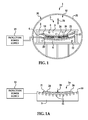
FIGS. 1-3 , an illustrative embodiment of the composite induction consolidation apparatus, hereinafter apparatus, is generally indicated byreference numeral 1. Theapparatus 1 may include anautoclave 30. Theautoclave 30 may have a conventional design with anautoclave housing 31 having anautoclave interior 32. Theautoclave 30 may have anoperating pressure 34 of at least about 200 psi. - An induction heated
tool 5 may be provided in theautoclave 30. The induction heatedtool 5 may include atool frame 2. In some embodiments, thetool frame 2 may be fiberglass. A base mandrel 9may be provided on thetool frame 2. An enclosinghood 3 may be pivotally attached to thebase mandrel 9 via at least one hinge 8. The enclosinghood 3 may be hydraulically-actuated to facilitate pivoting of the enclosinghood 3 with respect to thebase mandrel 9. Thebase mandrel 9 may have a contouredmandrel surface 10, whereas theenclosing hood 3 may have acontoured hood surface 4 which is complementary to the contouredmandrel surface 10 of thebase mandrel 9. In some embodiments, each of thebase mandrel 9 and the enclosinghood 3 may be a laminated tooling die including 0.185" thick 300-Series lamination. As shown inFIG. 2 , in some embodiments,mechanical pin connectors 40 may be used to connect the enclosinghood 3 to thebase mandrel 9. -
Multiple induction coils 14 may extend through each of thebase mandrel 9 and the enclosinghood 3 to facilitate selective heating of each. Theinduction coils 14 may be solenoidal water-cooled induction coils which envelope thecontoured mandrel surface 10 and the contouredhood surface 4. Aninduction power supply 15 may be electrically connected to theinduction coils 14. In some embodiments, theinduction power supply 15 may be a 2,000 KW induction power supply having an operating frequency of 1∼3 KHz. Abase mandrel facesheet 21 may be thermally coupled to theinduction coils 14 of thebase mandrel 9. An enclosinghood facesheet 20 may be thermally coupled to theinduction coils 14 of the enclosinghood 3. Each of thebase mandrel facesheet 21 and the enclosinghood facesheet 20 may be a thermally-conductive material such as, but not limited to, a ferromagnetic material, cobalt, nickel, or compounds thereof. In some embodiments, the base mandrel facesheet 21 and the enclosinghood facesheet 20 may be an INVAR® (64FeNi) smart susceptor. Thebase mandrel facesheet 21 may generally conform to the contouredmandrel surface 10 and the enclosinghood facesheet 20 may generally conform to the contouredhood surface 4. - In some embodiments,
cooling channels 6 may extend through each of the enclosinghood 3 and thebase mandrel 9. A cooling system (not shown) may be disposed in fluid communication with thecooling channels 6. The cooling system may be adapted to distribute a coolant (not shown) through thecooling channels 6 in operation of theapparatus 1, which will be hereinafter described. - In exemplary application of the
apparatus 1, a thermoplastic composite part orlayup 24 is placed in bagging 26 and evacuated onto thebase mandrel facesheet 21 on thebase mandrel 9. The enclosinghood facesheet 20 is disposed above and out of contact with thebagging 26 which encloses the thermoplasticcomposite part 24. Theinduction power supply 15 is then operated to power theinduction coils 14 in the enclosinghood 3 and in thebase mandrel 9. The induction coils 14 heat the enclosinghood facesheet 20 and thebase mandrel facesheet 21 to the Curie temperature point. The resulting change from magnetic to non-magnetic state of the enclosinghood facesheet 20 forces a leveling of the temperature of the enclosinghood facesheet 20 and the thermoplastic composite part 24 (∼2KHz frequency of operation and ∼0.125" susceptor thickness). In some applications, heating of the enclosinghood facesheet 20 and thebase mandrel facesheet 21 to the Curie temperature point may occur in 15 minutes or less. Since only the mass of the enclosinghood facesheet 20 and thebase mandrel facesheet 21 may be heated and large quantities of power can be directly coupled into the enclosinghood facesheet 20 and the base mandrel facesheet 21 from theinduction power supply 15, rapid heating of the thermoplasticcomposite part 24 can be achieved. - After the thermoplastic
composite part 24 is heated,pressure 34 is applied to the thermoplasticcomposite part 24 by pressurization operation of theautoclave 30. In some applications, thepressure 34 which is applied to the thermoplasticcomposite part 24 may be at least about 200 psi. This step consolidates the thermoplasticcomposite part 24. - In some applications, consolidation of the thermoplastic
composite part 24 may occur in 15 minutes or less. After consolidation of the thermoplasticcomposite part 24 is completed, forced gas cooling of the thermoplasticcomposite part 24 may be accomplished by cooling operation of theautoclave 30. This step rapidly and evenly cools the thermoplasticcomposite part 24 and may be accomplished in as quick as 20 minutes or less depending on the degree of crystallinity desired and the resin used for the thermoplasticcomposite part 24. After consolidation, the thermoplasticcomposite part 24 may be removed from the inductionheated tool 5. - It will be appreciated by those skilled in the art that high-performance thermoplastic composite components can be consolidated in the
autoclave 30 in a ∼50 minute cycle or less. Theapparatus 1 may enable the use of higher-performing composite materials and help eliminate current production bottlenecks in the production system. Furthermore, the technology may enable further leveraging of existing equipment by increasing product throughput without significant additional capital investments. - As shown in
FIG. 3 , an exemplary time vs.temperature graph 50 which characterizes operation of the composite induction consolidation apparatus is shown. Thegraph 50 includes a time axis 51 (X-axis), a temperature axis 52 (Y-axis) and a time vs.temperature curve 53. In exemplary application of theapparatus 1, the enclosinghood facesheet 20 of the enclosinghood 3 is heated from a baseline level (such as about 75 degrees F) to the Curie temperature point (about 705 degrees F) in about 15 minutes. The temperature of the enclosinghood facesheet 20 levels off and then gradually returns to the baseline level. Consolidation of the thermoplasticcomposite part 24 is then carried out. - Referring next to
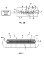
FIG. 1A , an alternative illustrative embodiment of a composite induction consolidation apparatus is generally indicated by reference numeral 1a. The apparatus 1a may include abase mandrel 9 having abase mandrel facesheet 21 on the contouredmandrel surface 10 thereof. Solenoidal magnetic induction coils 14 may extend through thebase mandrel 9. Application of the apparatus 1a may be as was heretofore described with respect to theapparatus 1 inFIG. 1 exceptambient pressure 28 applies the thermoplasticcomposite part 24 against thebase mandrel facesheet 21 during the consolidation process. - Referring next to
FIG. 1B , another alternative illustrative embodiment of a composite induction consolidation process is generally indicated by reference numeral 1b. The apparatus 1b may include abase mandrel 9 having abase mandrel facesheet 21 on the contouredmandrel surface 10 thereof. An enclosinghood 3 having a contouredhood surface 4 with a solenoidal magnetic induction coils 14 may be pivotally attached to thebase mandrel 9 via a hinge 8. Application of the apparatus 1b may be as was heretofore described with respect to the apparatus 1a inFIG. 1A , withambient pressure 28 applying the thermoplasticcomposite part 24 against thebase mandrel facesheet 21 during the consolidation process. The magnetic induction coils 14 of the enclosinghood 3 may generate additional heat to heat the thermoplasticcomposite part 24 during consolidation. - Referring next to
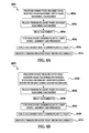
FIG. 4 , a flow diagram 400 of an illustrative embodiment of a composite induction consolidation method is shown. The compositeinduction consolidation method 400 may be implemented in operation of theapparatus 1 inFIG. 1 . Inblock 402, an autoclave with an induction heated tool having a base mandrel with a base mandrel facesheet and an enclosing hood with an enclosing hood facesheet in the autoclave is provided. Inblock 404, a thermoplastic composite part may be placed on the base mandrel facesheet of the base mandrel. A bagging material may be placed on the thermoplastic composite part and the part evacuated onto the base mandrel facesheet. Inblock 406, the facesheets may be heated to the Curie temperature point. In some applications, the facesheets may be heated to a temperature of at least about 705 degrees F by magnetic induction. Inblock 408, the thermoplastic composite part may be consolidated using pneumatic pressure generated in the autoclave. In some applications, the pneumatic pressure which is applied to the part may be at least about 200 psi. Inblock 410, the facesheets and the thermoplastic composite part may be cooled. In some embodiments, the facesheets and the thermoplastic composite part may be cooled using gas cooling. Inblock 412, the thermoplastic composite part may be removed from between the facesheets and from the autoclave. - Referring next to
FIG. 4A , a flow diagram 400a of an alternative illustrative embodiment of a composite induction consolidation method is shown. The compositeinduction consolidation method 400a may be implemented in operation of the apparatus 1a inFIG. 1A . Inblock 402a, an induction heated tool having a base mandrel with a base mandrel facesheet is provided. Inblock 404a, a thermoplastic part may be placed on the base mandrel facesheet. Inblock 406a, the base mandrel facesheet may be heated by magnetic induction. Inblock 408a, the thermoplastic part may be consolidated using ambient air pressure. Inblock 410a, the base mandrel facesheet and the thermoplastic part may be cooled. Inblock 412a, the thermoplastic part may be removed from the base mandrel facesheet. - Referring next to
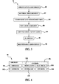
FIG. 4B , a flow diagram 400b of another alternative illustrative embodiment of a composite induction consolidation method is shown. The compositeinduction consolidation method 400b may be implemented in operation of the apparatus 1b inFIG. 1B . Inblock 402b, an induction heated tool having a base mandrel with a base mandrel facesheet and an enclosing hood with an enclosing hood facesheet is provided. Inblock 404b, a thermoplastic part may be placed on the base mandrel facesheet. Inblock 406b, the facesheets may be heated by magnetic induction. Inblock 408b, the thermoplastic part may be consolidated using ambient air pressure. Inblock 410b, the facesheets and the thermoplastic part may be cooled. Inblock 412b, the thermoplastic part may be removed from between the facesheets. - Referring next to
FIGS. 5 and 6 , embodiments of the disclosure may be used in the context of an aircraft manufacturing andservice method 78 as shown inFIG. 5 and anaircraft 94 as shown inFIG. 6 . During pre-production,exemplary method 78 may include specification anddesign 80 of theaircraft 94 andmaterial procurement 82. During production, component andsubassembly manufacturing 84 andsystem integration 86 of theaircraft 94 takes place. Thereafter, theaircraft 94 may go through certification anddelivery 88 in order to be placed inservice 90. While in service by a customer, theaircraft 94 may be scheduled for routine maintenance and service 92 (which may also include modification, reconfiguration, refurbishment, and so on). - Each of the processes of
method 78 may be performed or carried out by a system integrator, a third party, and/or an operator (e.g., a customer). For the purposes of this description, a system integrator may include without limitation any number of aircraft manufacturers and major-system subcontractors; a third party may include without limitation any number of vendors, subcontractors, and suppliers; and an operator may be an airline, leasing company, military entity, service organization, and so on. - As shown in
FIG. 6 , theaircraft 94 produced byexemplary method 78 may include anairframe 98 with a plurality ofsystems 96 and an interior 100. Examples of high-level systems 96 include one or more of apropulsion system 102, anelectrical system 104, ahydraulic system 106, and anenvironmental system 108. Any number of other systems may be included. Although an aerospace example is shown, the principles of the invention may be applied to other industries, such as the automotive industry. - The apparatus embodied herein may be employed during any one or more of the stages of the production and
service method 78. For example, components or subassemblies corresponding toproduction process 84 may be fabricated or manufactured in a manner similar to components or subassemblies produced while theaircraft 94 is in service. Also one or more apparatus embodiments may be utilized during the production stages 84 and 86, for example, by substantially expediting assembly of or reducing the cost of anaircraft 94. Similarly, one or more apparatus embodiments may be utilized while theaircraft 94 is in service, for example and without limitation, to maintenance andservice 92. - Although the embodiments of this disclosure have been described with respect to certain exemplary embodiments, it is to be understood that the specific embodiments are for purposes of illustration and not limitation, as other variations will occur to those of skill in the art.
- Another example of those embodiments would include where heating time adjustment and curing temperature adjustment from appropriate facesheet chemistry having a lower Curie point provides processing conditions for a thermoset polymer component
Claims (11)
- A composite induction consolidation apparatus for heating and consolidating a composite part, comprising:a base mandrel;a ferromagnetic base mandrel facesheet having a specific Curie temperature carried by said base mandrel;said base mandrel facesheet is adapted to support a composite part and allow ambient air pressure to compact the composite part against said base mandrel facesheet; andat least one magnetic induction coil in said base mandrel.
- The apparatus of claim 1 further comprising a enclosing hood carried by said base mandrel, with a ferromagnetic enclosing hood facesheet having a specific Curie temperature carried by said enclosing hood and adapted for positioning into adjacent proximity to the composite part, with at least one magnetic induction coil in said enclosing hood.
- The apparatus of claim 2 further comprising an autoclave and wherein said base mandrel and said enclosing hood are contained in said autoclave.
- The apparatus of claim 1 further comprising at least one cooling channel extending through said base mandrel.
- A composite induction consolidation apparatus for heating and consolidating a composite part, comprising:a base mandrel;a ferromagnetic base mandrel facesheet having a specific Curie temperature carried by said base mandrel;said base mandrel facesheet is adapted to support a composite part and allow ambient air pressure to compact the composite part against said base mandrel facesheet;at least one magnetic induction coil in said base mandrel;at least one cooling channel extending through said base mandrel;an enclosing hood carried by said base mandrel;a ferromagnetic enclosing hood facesheet having a specific Curie temperature carried by said enclosing hood and adapted for positioning into adjacent proximity to the composite part;at least one magnetic induction coil in said enclosing hood; andat least one cooling channel extending through said enclosing hood.
- The apparatus of claim 2 or claim 5 wherein said at least one magnetic induction coil in said base mandrel and in said enclosing hood comprises at least one solenoidal magnetic induction coil.
- The apparatus of claim 5 further comprising an autoclave and wherein said base mandrel and said enclosing hood are contained in said autoclave.
- The apparatus of claim 2 or claim 7 wherein each of said mandrel facesheet and said enclosing hood facesheet comprises a 64FeNi smart susceptor.
- A composite induction consolidation method, comprising:providing a base mandrel having a ferromagnetic base mandrel facesheet;placing a thermoplastic composite part on said base mandrel facesheet;heating said base mandrel facesheet and said thermoplastic composite part by magnetic induction;consolidating said thermoplastic composite part using ambient air pressure; andcooling said thermoplastic composite part.
- The method of claim 9 further comprising an enclosing hood having a ferromagnetic enclosing hood facesheet adjacent to said thermoplastic part and heating said enclosing hood facesheet.
- The method of claim 10 further comprising providing an autoclave and placing said base mandrel and said enclosing hood in said autoclave, and wherein consolidating said thermoplastic composite part using ambient air pressure comprises consolidating said thermoplastic composite part using ambient air pressure generated by said autoclave.
Applications Claiming Priority (1)
| Application Number | Priority Date | Filing Date | Title |
|---|---|---|---|
| US13/082,532 US10000026B2 (en) | 2011-04-08 | 2011-04-08 | Composite induction consolidation apparatus and method |
Publications (2)
| Publication Number | Publication Date |
|---|---|
| EP2508329A1 true EP2508329A1 (en) | 2012-10-10 |
| EP2508329B1 EP2508329B1 (en) | 2017-05-03 |
Family
ID=45936806
Family Applications (1)
| Application Number | Title | Priority Date | Filing Date |
|---|---|---|---|
| EP12159954.2A Active EP2508329B1 (en) | 2011-04-08 | 2012-03-16 | Composite induction consolidation apparatus and method |
Country Status (4)
| Country | Link |
|---|---|
| US (1) | US10000026B2 (en) |
| EP (1) | EP2508329B1 (en) |
| JP (1) | JP5901398B2 (en) |
| CA (1) | CA2770925C (en) |
Cited By (12)
| Publication number | Priority date | Publication date | Assignee | Title |
|---|---|---|---|---|
| WO2014130183A1 (en) * | 2013-02-19 | 2014-08-28 | The Boeing Company | Induction heating augmentation for thermal curing |
| WO2015006016A1 (en) * | 2013-07-09 | 2015-01-15 | The Boeing Company | Thermoplastic sandwich structures |
| FR3015919A1 (en) * | 2013-12-31 | 2015-07-03 | Roctool | DEVICE FOR HEATING A MOLD |
| US9267480B1 (en) | 2013-05-10 | 2016-02-23 | The Boeing Company | Electrical power generating engine flywheel with active torque control |
| US9469087B2 (en) | 2013-07-09 | 2016-10-18 | The Boeing Company | Thermoplastic and titanium sandwich structures |
| US9662742B2 (en) | 2013-07-09 | 2017-05-30 | The Boeing Company | Metallic bladders |
| CN107433716A (en) * | 2016-05-25 | 2017-12-05 | 利萨·德雷克塞迈尔有限责任公司 | For manufacturing the Method and kit for and vehicle interior trim part of vehicle interior trim part |
| US10029398B2 (en) | 2013-07-09 | 2018-07-24 | The Boeing Company | Consolidation of complex contoured thermoplastic structures |
| DE102018217017A1 (en) * | 2018-10-04 | 2020-04-09 | Premium Aerotec Gmbh | METHOD FOR PRODUCING A STRUCTURAL COMPONENT |
| US10618230B2 (en) | 2013-07-09 | 2020-04-14 | The Boeing Company | Thermoplastic structures |
| DE102019106107A1 (en) * | 2019-03-11 | 2020-09-17 | Deutsches Zentrum für Luft- und Raumfahrt e.V. | Tool device for producing a composite component and method for producing a component from a composite |
| US20220266480A1 (en) * | 2021-02-22 | 2022-08-25 | Airbus Operations Sas | Device for consolidating a part made of composite material by induction heating |
Families Citing this family (6)
| Publication number | Priority date | Publication date | Assignee | Title |
|---|---|---|---|---|
| KR102314956B1 (en) * | 2014-04-11 | 2021-10-19 | 록툴 | Device for heating a mold |
| FR3051135B1 (en) * | 2016-05-10 | 2019-05-31 | Roctool | DEVICE AND METHOD FOR MOLDING AND CONSOLIDATING A TEXTILE PREFORM |
| US10618213B2 (en) | 2017-02-17 | 2020-04-14 | The Boeing Company | Method and apparatus for continuously fabricating a composite sandwich structure |
| US10821651B2 (en) | 2017-02-17 | 2020-11-03 | The Boeing Company | Method and apparatus for continuously fabricating a composite sandwich structure |
| US11697895B2 (en) | 2019-03-27 | 2023-07-11 | The Boeing Company | Metal matrix composite tape fabrication, braiding, and consolidation to form metal matrix composite parts |
| US11897209B2 (en) | 2021-08-30 | 2024-02-13 | The Boeing Company | Composite forming apparatus, system and method |
Citations (4)
| Publication number | Priority date | Publication date | Assignee | Title |
|---|---|---|---|---|
| US5412185A (en) * | 1993-11-29 | 1995-05-02 | General Electric Company | Induction heating of polymer matrix composites in an autoclave |
| WO1996039291A1 (en) * | 1995-06-06 | 1996-12-12 | The Boeing Company | Method for achieving thermal uniformity in induction processing of organic matrix composites or metals |
| US20050035115A1 (en) * | 2003-08-13 | 2005-02-17 | The Boeing Company | Forming apparatus and method |
| US20090071217A1 (en) * | 2007-09-13 | 2009-03-19 | The Boeing Company | Composite Fabrication Apparatus and Method |
Family Cites Families (9)
| Publication number | Priority date | Publication date | Assignee | Title |
|---|---|---|---|---|
| US5176839A (en) | 1991-03-28 | 1993-01-05 | General Electric Company | Multilayered mold structure for hot surface molding in a short cycle time |
| US5645744A (en) | 1991-04-05 | 1997-07-08 | The Boeing Company | Retort for achieving thermal uniformity in induction processing of organic matrix composites or metals |
| US5591369A (en) | 1991-04-05 | 1997-01-07 | The Boeing Company | Method and apparatus for consolidating organic matrix composites using induction heating |
| US6915964B2 (en) * | 2001-04-24 | 2005-07-12 | Innovative Technology, Inc. | System and process for solid-state deposition and consolidation of high velocity powder particles using thermal plastic deformation |
| US6528771B1 (en) * | 2002-03-08 | 2003-03-04 | The Boeing Company | System and method for controlling an induction heating process |
| US6906300B2 (en) | 2003-08-13 | 2005-06-14 | The Boeing Company | Consolidation device and method |
| US8021595B2 (en) | 2004-07-20 | 2011-09-20 | B.I. Group, Plc | Composite material |
| US8372327B2 (en) | 2007-09-13 | 2013-02-12 | The Boeing Company | Method for resin transfer molding composite parts |
| JP2009292002A (en) | 2008-06-04 | 2009-12-17 | Toray Ind Inc | Method of manufacturing fiber-reinforced plastics |
-
2011
- 2011-04-08 US US13/082,532 patent/US10000026B2/en active Active
-
2012
- 2012-03-12 CA CA2770925A patent/CA2770925C/en active Active
- 2012-03-16 EP EP12159954.2A patent/EP2508329B1/en active Active
- 2012-04-04 JP JP2012085596A patent/JP5901398B2/en active Active
Patent Citations (4)
| Publication number | Priority date | Publication date | Assignee | Title |
|---|---|---|---|---|
| US5412185A (en) * | 1993-11-29 | 1995-05-02 | General Electric Company | Induction heating of polymer matrix composites in an autoclave |
| WO1996039291A1 (en) * | 1995-06-06 | 1996-12-12 | The Boeing Company | Method for achieving thermal uniformity in induction processing of organic matrix composites or metals |
| US20050035115A1 (en) * | 2003-08-13 | 2005-02-17 | The Boeing Company | Forming apparatus and method |
| US20090071217A1 (en) * | 2007-09-13 | 2009-03-19 | The Boeing Company | Composite Fabrication Apparatus and Method |
Cited By (20)
| Publication number | Priority date | Publication date | Assignee | Title |
|---|---|---|---|---|
| WO2014130183A1 (en) * | 2013-02-19 | 2014-08-28 | The Boeing Company | Induction heating augmentation for thermal curing |
| US9277594B2 (en) | 2013-02-19 | 2016-03-01 | The Boeing Company | Induction heating augmentation for thermal curing |
| US9267480B1 (en) | 2013-05-10 | 2016-02-23 | The Boeing Company | Electrical power generating engine flywheel with active torque control |
| US10029398B2 (en) | 2013-07-09 | 2018-07-24 | The Boeing Company | Consolidation of complex contoured thermoplastic structures |
| RU2667543C2 (en) * | 2013-07-09 | 2018-09-21 | Зе Боинг Компани | Thermoplastic sandwich structures |
| US10618230B2 (en) | 2013-07-09 | 2020-04-14 | The Boeing Company | Thermoplastic structures |
| US9358703B2 (en) | 2013-07-09 | 2016-06-07 | The Boeing Company | Thermoplastic sandwich structures |
| US9469087B2 (en) | 2013-07-09 | 2016-10-18 | The Boeing Company | Thermoplastic and titanium sandwich structures |
| US9662742B2 (en) | 2013-07-09 | 2017-05-30 | The Boeing Company | Metallic bladders |
| US10322564B2 (en) | 2013-07-09 | 2019-06-18 | The Boeing Company | Thermoplastic and titanium sandwich structures |
| WO2015006016A1 (en) * | 2013-07-09 | 2015-01-15 | The Boeing Company | Thermoplastic sandwich structures |
| US10173379B2 (en) | 2013-12-31 | 2019-01-08 | Roctool | Device for heating a mold |
| WO2015155369A1 (en) * | 2013-12-31 | 2015-10-15 | Roctool | Device for heating a mold |
| FR3015919A1 (en) * | 2013-12-31 | 2015-07-03 | Roctool | DEVICE FOR HEATING A MOLD |
| TWI691602B (en) * | 2013-12-31 | 2020-04-21 | 法商洛克杜爾公司 | A device for heating a mold |
| CN107433716A (en) * | 2016-05-25 | 2017-12-05 | 利萨·德雷克塞迈尔有限责任公司 | For manufacturing the Method and kit for and vehicle interior trim part of vehicle interior trim part |
| CN107433716B (en) * | 2016-05-25 | 2021-06-01 | 利萨·德雷克塞迈尔有限责任公司 | Method and tool for producing a vehicle interior part and vehicle interior part |
| DE102018217017A1 (en) * | 2018-10-04 | 2020-04-09 | Premium Aerotec Gmbh | METHOD FOR PRODUCING A STRUCTURAL COMPONENT |
| DE102019106107A1 (en) * | 2019-03-11 | 2020-09-17 | Deutsches Zentrum für Luft- und Raumfahrt e.V. | Tool device for producing a composite component and method for producing a component from a composite |
| US20220266480A1 (en) * | 2021-02-22 | 2022-08-25 | Airbus Operations Sas | Device for consolidating a part made of composite material by induction heating |
Also Published As
| Publication number | Publication date |
|---|---|
| JP2012218442A (en) | 2012-11-12 |
| EP2508329B1 (en) | 2017-05-03 |
| JP5901398B2 (en) | 2016-04-06 |
| CA2770925C (en) | 2018-01-16 |
| CA2770925A1 (en) | 2012-10-08 |
| US10000026B2 (en) | 2018-06-19 |
| US20120255947A1 (en) | 2012-10-11 |
Similar Documents
| Publication | Publication Date | Title |
|---|---|---|
| CA2770925C (en) | Composite induction consolidation apparatus and method | |
| US8017059B2 (en) | Composite fabrication apparatus and method | |
| EP2451622B1 (en) | Curing system and method using electromagnetic force and conductive heat transfer | |
| EP2547501B1 (en) | Method and apparatus for curing a composite part layup | |
| US9314975B1 (en) | High rate fabrication of compression molded components | |
| US10994450B2 (en) | Induction heating cells with cauls over mandrels methods of using thereof | |
| US11541575B2 (en) | Induction forming and curing of thermoset composite charges | |
| CN111300695B (en) | Method and system for curing thermoset composites | |
| EP2698242B1 (en) | Portable curing system | |
| US20190191495A1 (en) | Induction heating cells with controllable thermal expansion of bladders and methods of using thereof | |
| EP3915750A1 (en) | System and method for curing thermoset composites | |
| EP3668273B1 (en) | Induction heating system for molding a thermoplastic article and method for molding a thermoplastic article | |
| US20240066762A1 (en) | Curing Composites Out-Of-Autoclave Using Induction Heating with Smart Susceptors |
Legal Events
| Date | Code | Title | Description |
|---|---|---|---|
| PUAI | Public reference made under article 153(3) epc to a published international application that has entered the european phase |
Free format text: ORIGINAL CODE: 0009012 |
|
| 17P | Request for examination filed |
Effective date: 20120316 |
|
| AK | Designated contracting states |
Kind code of ref document: A1 Designated state(s): AL AT BE BG CH CY CZ DE DK EE ES FI FR GB GR HR HU IE IS IT LI LT LU LV MC MK MT NL NO PL PT RO RS SE SI SK SM TR |
|
| AX | Request for extension of the european patent |
Extension state: BA ME |
|
| 17Q | First examination report despatched |
Effective date: 20150506 |
|
| GRAP | Despatch of communication of intention to grant a patent |
Free format text: ORIGINAL CODE: EPIDOSNIGR1 |
|
| RIC1 | Information provided on ipc code assigned before grant |
Ipc: B29C 35/08 20060101ALI20161109BHEP Ipc: B29C 70/46 20060101AFI20161109BHEP Ipc: B29K 101/12 20060101ALN20161109BHEP |
|
| INTG | Intention to grant announced |
Effective date: 20161128 |
|
| RIN1 | Information on inventor provided before grant (corrected) |
Inventor name: MATSEN, MARC R. Inventor name: NEGLEY, MARK A. |
|
| GRAS | Grant fee paid |
Free format text: ORIGINAL CODE: EPIDOSNIGR3 |
|
| GRAA | (expected) grant |
Free format text: ORIGINAL CODE: 0009210 |
|
| AK | Designated contracting states |
Kind code of ref document: B1 Designated state(s): AL AT BE BG CH CY CZ DE DK EE ES FI FR GB GR HR HU IE IS IT LI LT LU LV MC MK MT NL NO PL PT RO RS SE SI SK SM TR |
|
| REG | Reference to a national code |
Ref country code: GB Ref legal event code: FG4D |
|
| REG | Reference to a national code |
Ref country code: AT Ref legal event code: REF Ref document number: 889503 Country of ref document: AT Kind code of ref document: T Effective date: 20170515 Ref country code: CH Ref legal event code: EP |
|
| REG | Reference to a national code |
Ref country code: IE Ref legal event code: FG4D |
|
| REG | Reference to a national code |
Ref country code: DE Ref legal event code: R096 Ref document number: 602012031822 Country of ref document: DE |
|
| REG | Reference to a national code |
Ref country code: NL Ref legal event code: MP Effective date: 20170503 |
|
| REG | Reference to a national code |
Ref country code: AT Ref legal event code: MK05 Ref document number: 889503 Country of ref document: AT Kind code of ref document: T Effective date: 20170503 |
|
| REG | Reference to a national code |
Ref country code: LT Ref legal event code: MG4D |
|
| PG25 | Lapsed in a contracting state [announced via postgrant information from national office to epo] |
Ref country code: HR Free format text: LAPSE BECAUSE OF FAILURE TO SUBMIT A TRANSLATION OF THE DESCRIPTION OR TO PAY THE FEE WITHIN THE PRESCRIBED TIME-LIMIT Effective date: 20170503 Ref country code: ES Free format text: LAPSE BECAUSE OF FAILURE TO SUBMIT A TRANSLATION OF THE DESCRIPTION OR TO PAY THE FEE WITHIN THE PRESCRIBED TIME-LIMIT Effective date: 20170503 Ref country code: LT Free format text: LAPSE BECAUSE OF FAILURE TO SUBMIT A TRANSLATION OF THE DESCRIPTION OR TO PAY THE FEE WITHIN THE PRESCRIBED TIME-LIMIT Effective date: 20170503 Ref country code: FI Free format text: LAPSE BECAUSE OF FAILURE TO SUBMIT A TRANSLATION OF THE DESCRIPTION OR TO PAY THE FEE WITHIN THE PRESCRIBED TIME-LIMIT Effective date: 20170503 Ref country code: AT Free format text: LAPSE BECAUSE OF FAILURE TO SUBMIT A TRANSLATION OF THE DESCRIPTION OR TO PAY THE FEE WITHIN THE PRESCRIBED TIME-LIMIT Effective date: 20170503 Ref country code: GR Free format text: LAPSE BECAUSE OF FAILURE TO SUBMIT A TRANSLATION OF THE DESCRIPTION OR TO PAY THE FEE WITHIN THE PRESCRIBED TIME-LIMIT Effective date: 20170804 Ref country code: NO Free format text: LAPSE BECAUSE OF FAILURE TO SUBMIT A TRANSLATION OF THE DESCRIPTION OR TO PAY THE FEE WITHIN THE PRESCRIBED TIME-LIMIT Effective date: 20170803 |
|
| PG25 | Lapsed in a contracting state [announced via postgrant information from national office to epo] |
Ref country code: BG Free format text: LAPSE BECAUSE OF FAILURE TO SUBMIT A TRANSLATION OF THE DESCRIPTION OR TO PAY THE FEE WITHIN THE PRESCRIBED TIME-LIMIT Effective date: 20170803 Ref country code: SE Free format text: LAPSE BECAUSE OF FAILURE TO SUBMIT A TRANSLATION OF THE DESCRIPTION OR TO PAY THE FEE WITHIN THE PRESCRIBED TIME-LIMIT Effective date: 20170503 Ref country code: RS Free format text: LAPSE BECAUSE OF FAILURE TO SUBMIT A TRANSLATION OF THE DESCRIPTION OR TO PAY THE FEE WITHIN THE PRESCRIBED TIME-LIMIT Effective date: 20170503 Ref country code: LV Free format text: LAPSE BECAUSE OF FAILURE TO SUBMIT A TRANSLATION OF THE DESCRIPTION OR TO PAY THE FEE WITHIN THE PRESCRIBED TIME-LIMIT Effective date: 20170503 Ref country code: IS Free format text: LAPSE BECAUSE OF FAILURE TO SUBMIT A TRANSLATION OF THE DESCRIPTION OR TO PAY THE FEE WITHIN THE PRESCRIBED TIME-LIMIT Effective date: 20170903 Ref country code: PL Free format text: LAPSE BECAUSE OF FAILURE TO SUBMIT A TRANSLATION OF THE DESCRIPTION OR TO PAY THE FEE WITHIN THE PRESCRIBED TIME-LIMIT Effective date: 20170503 Ref country code: NL Free format text: LAPSE BECAUSE OF FAILURE TO SUBMIT A TRANSLATION OF THE DESCRIPTION OR TO PAY THE FEE WITHIN THE PRESCRIBED TIME-LIMIT Effective date: 20170503 |
|
| PG25 | Lapsed in a contracting state [announced via postgrant information from national office to epo] |
Ref country code: CZ Free format text: LAPSE BECAUSE OF FAILURE TO SUBMIT A TRANSLATION OF THE DESCRIPTION OR TO PAY THE FEE WITHIN THE PRESCRIBED TIME-LIMIT Effective date: 20170503 Ref country code: DK Free format text: LAPSE BECAUSE OF FAILURE TO SUBMIT A TRANSLATION OF THE DESCRIPTION OR TO PAY THE FEE WITHIN THE PRESCRIBED TIME-LIMIT Effective date: 20170503 Ref country code: SK Free format text: LAPSE BECAUSE OF FAILURE TO SUBMIT A TRANSLATION OF THE DESCRIPTION OR TO PAY THE FEE WITHIN THE PRESCRIBED TIME-LIMIT Effective date: 20170503 Ref country code: EE Free format text: LAPSE BECAUSE OF FAILURE TO SUBMIT A TRANSLATION OF THE DESCRIPTION OR TO PAY THE FEE WITHIN THE PRESCRIBED TIME-LIMIT Effective date: 20170503 Ref country code: RO Free format text: LAPSE BECAUSE OF FAILURE TO SUBMIT A TRANSLATION OF THE DESCRIPTION OR TO PAY THE FEE WITHIN THE PRESCRIBED TIME-LIMIT Effective date: 20170503 |
|
| REG | Reference to a national code |
Ref country code: DE Ref legal event code: R097 Ref document number: 602012031822 Country of ref document: DE |
|
| PG25 | Lapsed in a contracting state [announced via postgrant information from national office to epo] |
Ref country code: IT Free format text: LAPSE BECAUSE OF FAILURE TO SUBMIT A TRANSLATION OF THE DESCRIPTION OR TO PAY THE FEE WITHIN THE PRESCRIBED TIME-LIMIT Effective date: 20170503 Ref country code: SM Free format text: LAPSE BECAUSE OF FAILURE TO SUBMIT A TRANSLATION OF THE DESCRIPTION OR TO PAY THE FEE WITHIN THE PRESCRIBED TIME-LIMIT Effective date: 20170503 |
|
| PLBE | No opposition filed within time limit |
Free format text: ORIGINAL CODE: 0009261 |
|
| STAA | Information on the status of an ep patent application or granted ep patent |
Free format text: STATUS: NO OPPOSITION FILED WITHIN TIME LIMIT |
|
| REG | Reference to a national code |
Ref country code: FR Ref legal event code: PLFP Year of fee payment: 7 |
|
| 26N | No opposition filed |
Effective date: 20180206 |
|
| PG25 | Lapsed in a contracting state [announced via postgrant information from national office to epo] |
Ref country code: SI Free format text: LAPSE BECAUSE OF FAILURE TO SUBMIT A TRANSLATION OF THE DESCRIPTION OR TO PAY THE FEE WITHIN THE PRESCRIBED TIME-LIMIT Effective date: 20170503 |
|
| REG | Reference to a national code |
Ref country code: CH Ref legal event code: PL |
|
| PG25 | Lapsed in a contracting state [announced via postgrant information from national office to epo] |
Ref country code: MC Free format text: LAPSE BECAUSE OF FAILURE TO SUBMIT A TRANSLATION OF THE DESCRIPTION OR TO PAY THE FEE WITHIN THE PRESCRIBED TIME-LIMIT Effective date: 20170503 |
|
| REG | Reference to a national code |
Ref country code: BE Ref legal event code: MM Effective date: 20180331 |
|
| REG | Reference to a national code |
Ref country code: IE Ref legal event code: MM4A |
|
| PG25 | Lapsed in a contracting state [announced via postgrant information from national office to epo] |
Ref country code: LU Free format text: LAPSE BECAUSE OF NON-PAYMENT OF DUE FEES Effective date: 20180316 |
|
| PG25 | Lapsed in a contracting state [announced via postgrant information from national office to epo] |
Ref country code: IE Free format text: LAPSE BECAUSE OF NON-PAYMENT OF DUE FEES Effective date: 20180316 |
|
| PG25 | Lapsed in a contracting state [announced via postgrant information from national office to epo] |
Ref country code: CH Free format text: LAPSE BECAUSE OF NON-PAYMENT OF DUE FEES Effective date: 20180331 Ref country code: LI Free format text: LAPSE BECAUSE OF NON-PAYMENT OF DUE FEES Effective date: 20180331 Ref country code: BE Free format text: LAPSE BECAUSE OF NON-PAYMENT OF DUE FEES Effective date: 20180331 |
|
| REG | Reference to a national code |
Ref country code: DE Ref legal event code: R082 Ref document number: 602012031822 Country of ref document: DE Representative=s name: MAIER, LL.M., MICHAEL C., DE Ref country code: DE Ref legal event code: R082 Ref document number: 602012031822 Country of ref document: DE Representative=s name: BOULT WADE TENNANT LLP, DE |
|
| PG25 | Lapsed in a contracting state [announced via postgrant information from national office to epo] |
Ref country code: MT Free format text: LAPSE BECAUSE OF NON-PAYMENT OF DUE FEES Effective date: 20180316 |
|
| REG | Reference to a national code |
Ref country code: DE Ref legal event code: R082 Ref document number: 602012031822 Country of ref document: DE Representative=s name: BOULT WADE TENNANT LLP, DE |
|
| PG25 | Lapsed in a contracting state [announced via postgrant information from national office to epo] |
Ref country code: TR Free format text: LAPSE BECAUSE OF FAILURE TO SUBMIT A TRANSLATION OF THE DESCRIPTION OR TO PAY THE FEE WITHIN THE PRESCRIBED TIME-LIMIT Effective date: 20170503 |
|
| PG25 | Lapsed in a contracting state [announced via postgrant information from national office to epo] |
Ref country code: HU Free format text: LAPSE BECAUSE OF FAILURE TO SUBMIT A TRANSLATION OF THE DESCRIPTION OR TO PAY THE FEE WITHIN THE PRESCRIBED TIME-LIMIT; INVALID AB INITIO Effective date: 20120316 Ref country code: PT Free format text: LAPSE BECAUSE OF FAILURE TO SUBMIT A TRANSLATION OF THE DESCRIPTION OR TO PAY THE FEE WITHIN THE PRESCRIBED TIME-LIMIT Effective date: 20170503 |
|
| PG25 | Lapsed in a contracting state [announced via postgrant information from national office to epo] |
Ref country code: MK Free format text: LAPSE BECAUSE OF NON-PAYMENT OF DUE FEES Effective date: 20170503 Ref country code: CY Free format text: LAPSE BECAUSE OF FAILURE TO SUBMIT A TRANSLATION OF THE DESCRIPTION OR TO PAY THE FEE WITHIN THE PRESCRIBED TIME-LIMIT Effective date: 20170503 |
|
| PG25 | Lapsed in a contracting state [announced via postgrant information from national office to epo] |
Ref country code: AL Free format text: LAPSE BECAUSE OF FAILURE TO SUBMIT A TRANSLATION OF THE DESCRIPTION OR TO PAY THE FEE WITHIN THE PRESCRIBED TIME-LIMIT Effective date: 20170503 |
|
| PGFP | Annual fee paid to national office [announced via postgrant information from national office to epo] |
Ref country code: FR Payment date: 20230327 Year of fee payment: 12 |
|
| PGFP | Annual fee paid to national office [announced via postgrant information from national office to epo] |
Ref country code: GB Payment date: 20230327 Year of fee payment: 12 Ref country code: DE Payment date: 20230329 Year of fee payment: 12 |
|
| P01 | Opt-out of the competence of the unified patent court (upc) registered |
Effective date: 20230516 |