EP2508285A1 - Dustproof structure for movable support section in cutting machine - Google Patents
Dustproof structure for movable support section in cutting machine Download PDFInfo
- Publication number
- EP2508285A1 EP2508285A1 EP10833061A EP10833061A EP2508285A1 EP 2508285 A1 EP2508285 A1 EP 2508285A1 EP 10833061 A EP10833061 A EP 10833061A EP 10833061 A EP10833061 A EP 10833061A EP 2508285 A1 EP2508285 A1 EP 2508285A1
- Authority
- EP
- European Patent Office
- Prior art keywords
- dust
- movable cover
- supporting annular
- annular portion
- elastic member
- Prior art date
- Legal status (The legal status is an assumption and is not a legal conclusion. Google has not performed a legal analysis and makes no representation as to the accuracy of the status listed.)
- Granted
Links
Images




Classifications
-
- B—PERFORMING OPERATIONS; TRANSPORTING
- B23—MACHINE TOOLS; METAL-WORKING NOT OTHERWISE PROVIDED FOR
- B23D—PLANING; SLOTTING; SHEARING; BROACHING; SAWING; FILING; SCRAPING; LIKE OPERATIONS FOR WORKING METAL BY REMOVING MATERIAL, NOT OTHERWISE PROVIDED FOR
- B23D47/00—Sawing machines or sawing devices working with circular saw blades, characterised only by constructional features of particular parts
-
- B—PERFORMING OPERATIONS; TRANSPORTING
- B25—HAND TOOLS; PORTABLE POWER-DRIVEN TOOLS; MANIPULATORS
- B25F—COMBINATION OR MULTI-PURPOSE TOOLS NOT OTHERWISE PROVIDED FOR; DETAILS OR COMPONENTS OF PORTABLE POWER-DRIVEN TOOLS NOT PARTICULARLY RELATED TO THE OPERATIONS PERFORMED AND NOT OTHERWISE PROVIDED FOR
- B25F5/00—Details or components of portable power-driven tools not particularly related to the operations performed and not otherwise provided for
- B25F5/02—Construction of casings, bodies or handles
-
- B—PERFORMING OPERATIONS; TRANSPORTING
- B27—WORKING OR PRESERVING WOOD OR SIMILAR MATERIAL; NAILING OR STAPLING MACHINES IN GENERAL
- B27B—SAWS FOR WOOD OR SIMILAR MATERIAL; COMPONENTS OR ACCESSORIES THEREFOR
- B27B9/00—Portable power-driven circular saws for manual operation
-
- B—PERFORMING OPERATIONS; TRANSPORTING
- B27—WORKING OR PRESERVING WOOD OR SIMILAR MATERIAL; NAILING OR STAPLING MACHINES IN GENERAL
- B27G—ACCESSORY MACHINES OR APPARATUS FOR WORKING WOOD OR SIMILAR MATERIALS; TOOLS FOR WORKING WOOD OR SIMILAR MATERIALS; SAFETY DEVICES FOR WOOD WORKING MACHINES OR TOOLS
- B27G19/00—Safety guards or devices specially adapted for wood saws; Auxiliary devices facilitating proper operation of wood saws
- B27G19/02—Safety guards or devices specially adapted for wood saws; Auxiliary devices facilitating proper operation of wood saws for circular saws
- B27G19/04—Safety guards or devices specially adapted for wood saws; Auxiliary devices facilitating proper operation of wood saws for circular saws for manually-operated power-driven circular saws
Definitions
- the second bearing is used in addition to the first bearing that rotatably supports the spindle on the main body case, so that the movable cover is rotatably supported on the bearing box. This may lead to increased costs. Therefore, it is desirable to provide a technique that is capable of reliably taking a dust-proof measure in the rotatably supporting portion of the movable cover without using such a special bearing.
- a first invention is a dust-proof structure of a rotatably supporting portion of a movable cover with respect to a main body case in a cutting machine that includes a base that is placed on an upper surface of a cutting object, a cutting machine main body that is supported on an upper surface side of the base, the cutting machine main body having the main body case and a circular cutting blade that is rotated by an electric motor, an upper portion of the cutting blade being covered by the main body case, a lower portion of the cutting blade being protruded from a lower surface side of the base, and a blade tip of a protruded portion thereof being openably and closably covered by the movable cover.
- the cutting blade is attached to a spindle that is rotatably supported by a bearing disposed in a bearing box of the main body case.
- the movable cover includes a cylindrical supporting annular portion and is rotationally supported by rotatably supporting the supporting annular portion on an outer circumferential side of the bearing box, so as to be capable of opening and closing the blade tip.
- the supporting annular portion of the movable cover is restricted from being displaced axially displaced by an axial restricting portion attached to the bearing box portion.
- An annular elastic member is interposed between an axial end surface of the supporting annular portion and the axial restricting portion while it is pressed, so that a dust entry path from a side of the cutting blade to an inner circumferential side of the supporting annular portion can be closed.
- a second invention corresponds to the dust-proof structure of the first invention, in which the elastic member is capable of being displaced in a diameter increasing direction against a biasing force in a diameter reducing direction, wherein a recessed portion for receiving at least a portion of the elastic member is provided between the supporting annular portion and the axial restricting portion, and in which at least one of the axial restricting portion, the supporting annular portion and the elastic member has an inclined surface that is inclined in a direction to displace the elastic member in the diameter increasing direction by pressing of the axial restricting portion.
- a dust-proof structure of a rotatably supporting portion of a movable cover with respect to a main body case in a cutting machine that includes a base that is placed on an upper surface of a cutting object, a cutting machine main body that is supported on an upper surface side of the base, the cutting machine main body having the main body case and a circular cutting blade that is rotated by an electric motor, an upper portion of the cutting blade being covered by the main body case, a lower portion of the cutting blade being protruded from a lower surface side of the base, and a blade tip of a protruded portion thereof being openably and closably covered by the movable cover, wherein the cutting blade is attached to a spindle that is rotatably supported by a bearing disposed in a bearing box of the main body case, wherein the movable cover includes a cylindrical supporting annular portion and is rotationally supported by rotatably supporting the supporting annular portion on an outer circumferential side of the bearing box, so as to be capable of opening and closing the blade
- dust-proof performance can be further increased by both of the labyrinth structure and the elastic member.
- a dust-proof structure of a rotatably supporting portion of a movable cover with respect to a main body case in a cutting machine that includes a base that is placed on an upper surface of a cutting object, a cutting machine main body that is supported on an upper surface side of the base, the cutting machine main body having the main body case and a circular cutting blade that is rotated by an electric motor, an upper portion of the cutting blade being covered by the main body case, a lower portion of the cutting blade being protruded from a lower surface side of the base, and a blade tip of a protruded portion thereof being openably and closably covered by the movable cover, wherein the cutting blade is attached to a spindle that is rotatably supported by a bearing disposed in a bearing box of the main body case, wherein the movable cover includes a cylindrical supporting annular portion and is rotationally supported by rotatably supporting the supporting annular portion on an outer circumferential side of the bearing box, so as to be capable of opening and closing the blade
- the dust-proof structure of related invention 4 since a labyrinth structure capable of bending the dust entry path is provided between the circumferential peripheral edge portion of the dust-proof washer and the supporting annular portion, dust-proofness therein can be increased while a smooth opening and closing operation of the movable cover is secured.
- the dust-proof structure as defined in related invention 4 wherein fins are provided to the dust-proof washer, so that the dust-proof washer can function as a dust-proof fan capable of blowing away dust when the spindle is rotated.
- the dust-proof washer that rotates integrally with the spindle can function as the dust-proof fan that us capable of blowing away the generated dust, the dust-proofness of the supporting annular portion can be further increased in combination with the labyrinth structure.
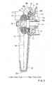
- FIG. 1 shows a cutting machine 1 which is referred to as a handheld circular saw.
- the cutting machine 1 includes a base 2 that is placed on an upper surface of a cutting object W, and a cutting machine main body 10 that is supported on an upper surface side of the base 2.
- the cutting machine main body 10 includes an electric motor 12 as a drive source, which motor is positioned in a rear face of the main body case 11.
- a rotational output of the electric motor 12 is transmitted to a spindle 14 via a reduction gear train 13.
- the reduction gear train 13 is composed of a pinion gear 12a of the electric motor 12 and a drive gear 13a meshing with each other and is received within a gear box 18.
- the drive gear 13a is secured to the spindle 14.
- the spindle 14 is rotatably supported on the main body case 11 via bearings 15 and 16.
- the front face-side bearing 15 is held on an inner circumferential side of a bearing box 17.
- a seal member 15a for dust-proofing is attached to a front side of the bearing 15 while it is positioned in the inner circumferential side of the bearing box 15.
- the rear face-side bearing 16 is held on the gear box 18.
- the bearing box 17 is attached to a front face side of the gear box 18.
- a distal end side of the spindle 14 protrudes from the bearing box 17 and reaches an interior portion of the main body case 11.
- a circular cutting blade 20 is attached to a distal end portion of the spindle 14.
- the cutting blade 20 is attached to the spindle 14 while being held between an outer side fixture flange 21 and an inner side fixture flange 22 in a thickness direction, so as to not move in an axial direction and a rotational direction.
- a holding condition of the fixture flanges 21 and 22 is secured by a fixing screw 23 threaded into a distal end of the spindle 14.
- a circumferential peripheral portion (a blade tip) corresponding to a substantially upper half circumference of the cutting blade 20 is covered by a cover portion 11a of the main body case 11.
- a substantially lower half circumference of the cutting blade 20 is protruded from a lower surface side of the base 2 via a window portion 2a formed in the base 2.
- a protruded portion of the cutting blade 20 that is protruded from the lower surface side of the base 2 can be cut into the cutting object W.
- the circumferential peripheral portion (the blade tip) of the cutting blade 20 corresponding to the range protruded from the lower surface side of the base 2 is covered by a movable cover 25.
- the movable cover 25 is rotatably supported on the bearing box 17.
- the movable cover 25 is configured to move between a closed position in which the blade tip of the cutting blade 20 is entirely covered thereby within the range protruded from the lower surface side of the base 2 and a fully opened position in which the blade tip of the cutting blade 20 is entirely exposed within the range protruded from the lower surface side of the base 2.
- the movable cover 25 and the bearing box 17 that supports the movable cover 25 are shown in FIG. 2 in detail.
- the movable cover 25 includes a cross-sectionally U-shaped cover portion 25a that covers the blade tip of the cutting blade 20, and a cylindrical supporting annular portion 25b that supports the cover portion 25a on the bearing box 17.
- a rotating boss portion 17a of the bearing box 17 is inserted into an inner circumferential side of the supporting annular portion 25b, so that the movable cover 25 can be rotatably supported to rotate coaxially with the spindle 14.
- An internal diameter of the supporting annular portion 25b with respect to an external diameter of the rotating boss portion 17a is appropriately set such that looseness cannot be formed therebetween within a range in which a smooth rotational action of the movable cover 25 is not impeded, and a clearance formed therebetween is set to be as small as possible.
- a retaining ring 19 is attached to the outer circumference of the bearing box 17, which ring is positioned in a front face side of the rotating boss portion 17a.
- the supporting annular portion 25b is restricted from being axially displaced by the axial restricting portion 17b and the retaining ring 19.
- the retaining ring 19 may function as an axial restricting portion that restricts the supporting annular portion 25b from displacing toward a front face side thereof.
- a circular flat-plate-shaped washer 19a is interleaved between the supporting annular portion 25b and the retaining ring 19.
- the supporting annular portion 25b is positioned between the retaining ring 19 as the axial restricting portion and the axial restricting portion 17b, so that axial displacement (backlash) thereof can be restricted.
- deflection (backlash) of the movable cover 25 in right-and-left directions (in directions of arrows X in FIG. 1 ) of the cutting advancing direction is restricted.
- a dust-proof structure is disposed between the supporting annular portion 25b and the bearing box 17 in order to prevent dust such as cutting powder from entering therein. Various embodiments of this dust-proof structure will be described below.
- a dust-proof structure 30 of a first embodiment includes a configuration in which a ring spring 31 is disposed between a front face-side end surface of the supporting annular portion 25b and the washer 19a.
- the ring spring 31 corresponds to an elastic member described in the claims.
- the ring spring 31 is molded by using a high-strength resin (for example, polyacetal) having high slidability and reduced coefficient of friction and has an annular shape (C-shape), so as to have a biasing force in a diameter reducing direction.
- the ring spring 31 is fitted in an annular recessed portion 25c that is formed in the front face-side end surface of the supporting annular portion 25b. As shown in FIG.
- an inclined surface 25d is formed between a side wall portion positioned in a smaller-diameter side (a lower side in FIG. 3 ) of the recessed portion 25c and a bottom portion thereof.
- the inclined surface 25d is inclined in a direction that goes down toward a side wall portion positioned in an outer circumferential side (an upper side in FIG. 3 ). Because the supporting annular portion 25b is disposed between the retaining ring 19 as the axial restricting portion and the axial restricting portion 17b so as to be restricted from being axially displaced, the ring spring 31 is attached while it is pushed into the recessed portion 25c. As a result, the ring spring 31 is attached in a condition in which it is pressed against the inclined surface 25d.
- the ring spring 31 is held within the recessed portion 25c in a condition in which it is displaced in a diameter increasing direction against the biasing force thereof.
- the ring spring 31 is pressed against the washer 19a (toward the retaining ring 19) by an axial component of the biasing force thereof to the inclined surface 25d.
- the ring spring 31 has a pressing surface against the inclined surface 25d and a pressing surface against the washer 19a that are respectively formed as flat surfaces 31a and 31b over the entire circumference thereof. Therefore, the ring spring 31 is pressed against the inclined surface 25d and the washer 19a in a surface contact manner.
- the ring spring 31 is not simply circular in cross section and has the flat surfaces 31a and 31b that are formed over the entire circumference thereof, so as to be respectively pressed against the inclined surface 25d and the washer 19a in the surface contact manner. Therefore, the ring spring 31 can reliably transmit a pressing force while securing high slidability, so as to be smoothly deformed in the diameter increasing direction and the diameter reducing direction. Furthermore, the ring spring 31 may provide an axial elastic force to the supporting annular portion 25b, so as to prevent the backlash thereof and to ensure a dust-blocking function (a dust-proof function).
- the ring spring 31 is elastically pressed against the recessed portion 25c of the supporting annular portion 25b and the washer 19a over the entire circumference thereof. Therefore, a dust entry path from a dust generation site (a side of the cutting blade 20) to the inner circumferential side of the supporting annular portion 25b is closed in an intermediate portion thereof, so that the dust can be prevented from entering the inner circumferential side of the supporting annular portion 25b.
- the ring spring 31 having high slidability is pressed against the retaining ring 19 as the axial restricting portion via the washer 19a, thereby performing dust-proofing.
- the ring spring 31 having a larger diameter can be pressed against the retaining ring via the washer that can be machined in an arbitrary size. Therefore, with regard to the size of the ring spring that can be used, a degree of freedom in selection can be increased.
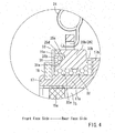
- an intermediate sleeve 32 can be interposed between the supporting annular portion 25b of the movable cover 25 and the bearing box 17 (a second embodiment).
- the intermediate sleeve 32 can be molded by using a high-strength resin having high slidability (reduced frictional resistance), and can include a cylindrical body 32a that is sandwiched between an inner circumferential surface of the supporting annular portion 25b and the rotating boss portion 17a of the bearing box 17, and a flange portion 32b that projects from a rear face-side end portion of the cylindrical body 32a and is sandwiched between a rear face-side end portion of the supporting annular portion 25b and the axial restricting portion 17b of the bearing box 17.
- the intermediate sleeve 32 is secured to an outer circumferential side of the rotating boss portion 17a, so as to not be displaced in a rotational direction and an axial direction.
- the clearance between the supporting annular portion 25b of the movable cover 25 and the cylindrical body 32a of the intermediate sleeve 32 can be further reduced, so as to enhance the dust-proofness. Further, backlash between the supporting annular portion 25b and the cylindrical portion 32a can be eliminated, so that the movable cover 25 can be smoothly opened and closed.
- a dust-proof structure 40 of a third embodiment in which a further change is added is shown in FIG. 5 .
- two rubber rings 42 and 43 are used as the elastic member in place of the ring spring 31 in the first and second embodiments. Elements that are the same in the first and second embodiments will be identified by the same reference numerals and a detailed description of such elements may be omitted.
- a front portion of the spindle 14 is rotatably supported by the bearing 15.
- the bearing 15 is held on the bearing case 17.
- a supporting annular portion 41a of a movable cover 41 is rotatably supported on the rotating boss portion 17a of the bearing case 17.
- the supporting annular portion 41a has a cylindrical shape, and is restricted from being axially displaced by the axial restricting portion 17b of the bearing case 17 and the retaining ring 19. Further, an internal diameter of the supporting annular portion 41a and an external diameter of the rotating boss portion 17a are set to such dimensions that allow the movable cover 41 to smoothly rotate within a range in which deflection (displacement in directions of arrow X in FIG. 1 ) is not generated therein. Similar to the first and second embodiments, the washer 19a is interleaved between a front face-side end surface of the supporting annular portion 41a and the retaining ring 19.
- the rubber rings 42 and 43 each having an annular shape are respectively attached to both of the front face-side end surface and a rear face-side end surface of the supporting annular portion 41a.
- inexpensive members that are referred to as O-rings are used for the rubber rings 42 and 43.
- the rubber rings 42 and 43 can be reduced in cost as compared to the ring spring 31.
- Both of the rubber rings 42 and 43 are respectively fitted into recesses 41b and 41c that are formed in both of the end surfaces of the supporting annular portion 41 a. Similar to the first and second embodiments, inclined surfaces are respectively formed in the recesses 41b and 41c, and the rubber rings 42 and 43 are respectively pressed against the inclined surfaces.
- the front face-side rubber ring 42 is pressed against the inclined surface of the recessed portion 41b with an appropriate pressing force by the washer 19a, so as to be expanded in a diameter increasing direction.
- the rear face-side rubber ring 43 is pressed against the inclined surface of the recessed portion 41c with an appropriate pressing force by the axial restricting portion 17b, so as to be expanded in a diameter increasing direction.
- the rubber rings 42 and 43 are respectively elastically pressed against the washer 19a and the axial restricting portion 17b with reaction forces caused by pressing.
- a dust entry path from a side of the cutting blade 20 (a dust generation site) to an inner circumferential side of the supporting annular portion 41a is closed in an intermediate portion thereof and in both of a front face side and a rear face side by the two rubber rings 42 and 43 thus attached.
- the dust-proof structure 40 of the third embodiment thus constructed, the dust can be prevented from entering the inner circumferential side of the supporting annular portion 41a and surroundings thereof by the two rubber rings 42 and 43. Therefore, it is possible to secure high dust-proofness even if an enough clearance is set between the supporting annular portion 41a and the supporting boss portion 17a of the bearing case 17 in order to secure a smooth opening and closing operation of the movable cover 41.
- a bearing conventionally used to rotationally support a movable cover can be omitted. As a result, it is possible to reduce costs of a supporting structure.
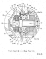
- a dust-proof structure 50 according to a fourth embodiment is shown in FIG. 6 .
- the fourth embodiment is a dust-proof structure that is mainly based on a labyrinth structure unlike an elastic member sealing structure in the first to third embodiments, which corresponds to an embodiment of a related invention. Elements that are the same in the first to third embodiments will be identified by the same reference numerals and a detailed description of such elements may be omitted.
- a supporting annular portion 51a of a movable cover 51 is rotatably supported on a rotating boss portion 52a of a bearing box 52.
- the movable cover 51 is biased in a closing direction by the tension spring 24 that is disposed between the supporting annular portion 51a and the bearing box 52.
- the supporting annular portion 51a is restricted from being displaced toward a front face side by the retaining ring 19 attached to the bearing box 52, and is restricted from being displaced toward a rear face side by an axial restricting portion 52b that is attached to a rear face-side end portion of the bearing box 52.
- a recessed portion 51c is formed in a front face-side end surface of the supporting annular portion 51a over the entire circumference thereof.
- a circumferential peripheral edge portion of a dust-proof washer 53 enters the recessed portion 51 c. The dust-proof washer 53 is held between a flange portion 14a of the spindle 14 and the inner side fixture flange 22, so as to rotate integrally with the spindle 14.
- the circumferential peripheral edge portion of the dust-proof washer 53 is bent at a right angle toward the rear face side, so as to form a bent portion 53a that is introduced into the recessed portion 51c without contacting the same.
- a dust entry path from a side of the cutting blade 20 to an inner circumferential side of the supporting annular portion 51a is bent in an intermediate portion thereof, so that the labyrinth structure (a path bending structure) can be formed.
- dust-proofing in a clearance between the front face-side end surface of the supporting annular portion 51a and the retaining ring 19 and in the inner circumferential side of the supporting annular portion 51a can be performed.
- a dust-proof rim 52c is formed in an axial restricting portion 52b of a bearing box 52 over the entire circumference thereof while it is projected toward the front face side. As shown therein, the dust-proof rim 52c is projected so as to cover an outer circumferential side of a rear face-side end portion of the supporting annular portion 51a.
- the clearance between the rear face-side end portion of the supporting annular portion 51a and the axial restricting portion 52b is shielded by the dust-proof rim 52c from the side of the cutting blade 20 (the dust generation site), so that dust-proofing in a clearance between the rear face-side end portion of the supporting annular portion 51a and the axial restricting portion 52b and in the inner circumferential side of the supporting annular portion 51a can be performed.
- a plurality of fins 53b to 53b are provided to a front face-side circumferential periphery of the dust-proof washer 53 so as to project toward the front face side.
- the fins 53b to 53b are positioned at regular intervals in a circumferential direction, and are projected so as to not interfere with the fixture flange 22. Due to the fins 53b to 53b, the dust-proof washer 53, when rotates integrally with the spindle 14, can function as a dust-proof fan.
- a front face side of the supporting annular portion 51a of the movable cover 51 is shielded from the side of the cutting blade 20 by the bent portion 53a of the dust-proof washer 53, and a rear face side thereof is shielded from the side of the cutting blade 20 by the dust-proof rim 52c of the gear box 52.
- the dust can be prevented from entering the clearance between the front face-side end portion of the supporting annular portion 51a and the retaining ring 19 and the clearance between the rear face-side end portion of the supporting annular portion 51a and the axial restricting portion 52b.
- the dust can be prevented from entering the inner circumferential side of the supporting annular portion 51a. Therefore, in order to secure a smooth opening and closing operation of the movable cover 51, an enough clearance can be set between the supporting annular portion 51a and the rotating boss portion 52a of the bearing box 52.
- a special bearing a second bearing
- the dust-proof washer 53 that rotates integrally with the spindle 14 can function as the dust-proof fan. Therefore, the dust generated in the side of the cutting blade 20 can be prevented from being easily blown toward the supporting annular portion 51a. As a result, a rotatably supporting portion in which the supporting annular portion 51a is supported on the bearing box 52 can have increased dust-proofness. Moreover, according to the dust-proof structure 50 of the fourth embodiment, both of the bent portion 53a of the dust-proof washer 53 and the dust-proof rim 52c of the bearing box 52 do not contact the supporting annular portion 51a. Thus, a rotational operation of the supporting annular portion 51a with respect to the bearing box 52 cannot be obstructed, so that an opening and closing operation of the movable cover 51 can be smoothly performed.
- a dust-proof structure 60 according to a fifth embodiment that is modified from the fourth embodiment is shown in FIG. 7 .
- the dust-proof structure 60 of the fifth embodiment is different from the fourth embodiment in that a dust-proof fan 61 is used instead of the dust-proof washer 53 of the fourth embodiment.
- Elements that are the same in the fourth embodiment will be identified by the same reference numerals and a detailed description of such elements may be omitted.
- the dust-proof fan 61 is circumferentially integrally attached to the inner side fixture flange 22. Therefore, the dust-proof fan 61 can rotate integrally with the spindle 14.
- a plurality of fins 61a to 61a are circumferentially provided to the dust-proof fan 61.
- each of the fins 61 a is shaped to be elongated toward the rear face side as it is closer to an outer periphery thereof.
- a rear face-side protruding portion 61b of each of the fins 6 1 a enters the recessed portion 51c formed in the front face-side end portion of the supporting annular portion 51a without interfering therewith.
- the dust-proof fan 61 can rotate integrally with the spindle 14. Therefore, the rear face-side protruding portion 61b of each of the fins 61a of the dust-proof fan 61 moves at high speed along an interior surface of the recessed portion 5 1 c.
- an outer circumferential side (the side of the cutting blade 20) of the clearance between the front face-side end surface of the supporting annular portion 51a and the retaining ring 19 can substantially be shielded by the fins 61a to 61a of the dust-proof fan 61.
- the clearance between the front face-side end surface of the supporting annular portion 51a and the retaining ring 19 that restricts the supporting annular portion 51a from displacing toward the front face side can be shielded from the side of the cutting blade 20 by the rear face-side protruding portion 61b of each of the fins 61a rotating at high speed.
- the clearance between the rear face-side end surface of the supporting annular portion 51a and the axial restricting portions 52b that restricts the supporting annular portion 51a from displacing toward the rear face side can be shielded from the side of the rotary knife 20 by the dust-proof rim 52c.
- the dust can be prevented from entering the inner circumferential side of the supporting annular portion 51a.
- the rotatably supporting portion in which the supporting annular portion 51a is supported on the bearing box 52 can have increased dust-proofness.
- the second bearing used in the conventional art can be omitted, so as to achieve cost reduction.
- the dust generated in the side of the cutting blade 20 can be blown away by the dust-proof fan 61.
- the high dust-proofness near the supporting annular portion 51a can be secured in this respect.
- a dust-proof structure 70 of a sixth embodiment is shown in FIG. 8 .
- the sixth embodiment is constructed to have both of the elastic member sealing structure and the labyrinth structure, so that dust-proof performance can be further increased. Elements that are the same in the embodiments described above will be identified by the same reference numerals and a detailed description of such elements may be omitted.
- the dust-proof structure 70 of the sixth embodiment has features in the structure of a supporting annular portion 71a of a movable cover 71 and a bearing box 72.
- the supporting annular portion 71a of the movable cover 71 is rotatably supported on a rotating boss portion 72a of the bearing box 72.
- the supporting annular portion 71a is restricted from being displaced toward a front face side thereof by the retaining ring 19.
- the supporting annular portion 71a is restricted from being displaced toward a rear face side thereof by an axial restricting portion 72b that is attached to the bearing box 72.
- a ring-shaped dust-proof cover 73 is attached to the front face side of the supporting annular portion 71a.
- a clearance between the retaining ring 19 and a front face-side end surface of the supporting annular portion 71a is shielded from the side of the cutting blade 20 (the dust generation site) by the dust-proof cover 73.
- Integrally provided to the supporting annular portion 71a is a second dust-proof wall portion 71b that projects toward the rear face side thereof.
- the second dust-proof wall portion 71b is cylindrically formed along an outer circumferential side of the supporting annular portion 71a. Also, integrally provided to the axial restricting portion 72b of the bearing box 72 is a cylindrical first dust-proof wall portion 72c that projects toward a front face side thereof. The first dust-proof wall portion 72c formed in the bearing box 72 enters an inner circumferential side of the second dust-proof wall portion 71b formed in the supporting annular portion 71a.
- a recessed portion 72d similar to the recessed portion 25c of the first embodiment is formed in the front face side of the axial restricting portion 72b of the bearing box 72. The recessed portion 72d is positioned in an outer circumferential side of the first dust-proof wall portion 72c.
- an annular ring spring 74 is fitted into the recessed portion 72d.
- An inclined surface is formed in an inner circumferential side of the recessed portion 72d so as to be positioned between a side wall portion and a bottom portion thereof.
- the ring spring 74 is pressed against the inclined surface.
- the ring spring 74 is pressed against the inclined surface formed in the recessed portion 72d by the second dust-proof wall portion 71b formed in the supporting annular portion 71a, so as to be displaced in a diameter increasing direction against a biasing force thereof.
- the ring spring 74 can be pressed against a distal end surface of the second dust-proof wall portion 71b by an axial component of a reaction force of the biasing force.
- the tension spring 24 for biasing the movable cover 71 toward a closing direction is interposed between the supporting annular portion 71a and the bearing box 72.
- the tension spring 24 is positioned along an outer circumferential surface of the second dust-proof wall portion 71b formed in the supporting annular portion 71a.
- the clearance between the front face-side end surface of the supporting annular portion 71a and the retaining ring 19 can be shielded from the side of the cutting blade 20 (the dust generation site) by the dust-proof washer 73, so that dust-proofing therein can be performed.
- a clearance between the rear face side of the supporting annular portion 71a and the axial restricting portions 72b can be shielded from the side of the cutting blade 20 by the second dust-proof wall portion 71b and the first dust-proof wall portion 72c, so that dust-proofing therein can be performed.
- a more complicated bent path (a labyrinth structure) is formed in an intermediate portion of a dust entry path from the side of the cutting blade 20 to an inner circumferential side of the supporting annular portion 71a by the second dust-proof wall portion 71b of the supporting annular portion 71a and the dust-proof wall portion 72 of the bearing box 72, the dust can be reliably prevented from entering the inner circumferential side of the supporting annular portion 71a in this respect.
- the inclined surface 25d is formed within the recessed portion 25c such that the ring spring 31 can be displaced in the diameter increasing direction.
- an inclined surface can be formed in the retaining ring 19 or the washer 19a such that the ring spring 31 as the elastic member can be reliably displaced in the diameter increasing direction.
- the ring spring 31 is interposed between the front-side end surface (the recessed portion 25c) of the supporting annular portion 25b and the retaining ring 19 as the front-side axial restricting portion.
- the ring spring 31 can be interposed between the back-side end surface of the supporting annular portion 25b and the back-side axial restricting portion 17b.
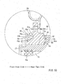
- FIGS. 9 and 10 Such a structure is shown in FIGS. 9 and 10 .
- a dust-proof structure 80 shown in FIG. 9 a recessed portion 81 is formed in a back surface of the supporting annular portion 25b, and a mouth corner portion 81a of the recessed portion 81 is pressed against a flat surface 82a of an elastic member 82.
- a front side of the supporting annular portion 25b is provided with the dust-proof structure 30 of the first embodiment.
- the recessed portion 81 can be formed as a shouldered portion by removing an outer circumferential-side wall portion 83 (a portion to the right of a broken line in FIG. 9 ) thereof.
- an annular wall portion that projects rearward can be provided to the back surface of the supporting annular portion 25b in place of the recessed portion, so that a corner portion of the wall portion can be pressed against the inclined surface of the elastic member.
- an annular wall portion 91 that projects rearward is formed in the back surface of the supporting annular portion 25b, and the wall portion 91 includes an inclined surface 91a that is capable of displacing an elastic member 92 in the diameter increasing direction.
- the elastic member 92 is received within a recessed portion 93 that is formed in the axial restricting portion 17b. Even by the dust-proof structure 90, the elastic member 92 can be pressed between the inclined surface 91a of the supporting annular portion 25b and the recessed portion 93 of the axial restricting portion 17b, so as to be displaced in the diameter increasing direction. Thus, along with the front-side dust-proof structure 30, the dust entry path into the inner circumferential side of the supporting annular portion 25b can be closed while the smooth opening and closing operation of the movable cover 25 can be secured. Further, in this case, the recessed portion 93 can be formed as a shouldered portion by removing an outer circumferential-side wall portion 94 (a portion to the left of a broken line in FIG.
- the ring spring 31 has the flat surface 31a as the pressing surface against the inclined surface 25d, so as to be pressed against the inclined surface 25d in the surface contact manner. Further, the ring spring 31 has the flat surface 31b as the pressing surface against the retaining ring 19 (the washer 19a), so as to be pressed against the retaining ring 19 in the surface contact manner. However, the flat surfaces 31a and 31b may be omitted. Further, the handheld cutting machine that is moved on the cutting object W by a user is exemplified as the cutting machine. However, the exemplified dust-proof structures can be applied to a tabletop type cutting machine in which a cutting blade is cut into the cutting object secured on a table by lowering a cutting machine main body with respect to the cutting object.
Landscapes
- Engineering & Computer Science (AREA)
- Mechanical Engineering (AREA)
- Life Sciences & Earth Sciences (AREA)
- Wood Science & Technology (AREA)
- Forests & Forestry (AREA)
- Sawing (AREA)
Abstract
Description
- The present invention relates to a dust-proof structure of a movable cover support portion of a cutting machine that is suitable for a case in which it is required to have high dust-proofness against dust generated by cutting processing or grinding processing.
- A handheld cutting machine, which is constructed such that a user holds the machine by hand and performs cutting processing while moving the same along a cutting object, is configured such that a cutting machine main body is supported on an upper surface side of a base that is placed on the cutting object. The cutting machine main body includes a circular cutting blade that is rotated by an electric motor. The cutting blade is arranged such that a lower portion thereof is protruded from a lower surface side of the base to be cut into the cutting object. An upper portion of the cutting blade is covered by a main body case, and the lower portion protruded from the lower surface side of the base is covered by a movable cover. The movable cover is rotatably supported on the main body case, so as to be opened and closed depending on a cutting amount of the cutting blade into the cutting object, and is spring-biased to a closing direction.
This movable cover is positioned in the upper surface side of the base and is rotatably supported on an outer circumferential side of a cylindrical bearing box of the main body case. The bearing box has a bearing that rotatably supports a spindle to which the cutting blade is attached.
Cutting powder blown up from a cutting part by the cutting processing can be scattered into the main body case including surroundings of the bearing box. Conversely, in a rotatably supporting portion of the movable cover, formed between the movable cover and the bearing box is an appropriate clearance (gap) in a radial direction and an axial direction in order to secure smooth opening and closing operation of the movable cover. As a result, dust such as the cutting powder can enter the clearance between the rotatably supporting portion of the movable cover and the bearing box. This may disturb a smooth opening and closing operation of the movable cover. Conventionally, a technique taught by, for example, a following Patent Document is suggested as a dust-proof measure. In this conventional technique, a second bearing for supporting the movable cover is attached to the outer circumferential side of the bearing box apart from the bearing for supporting the spindle. The movable cover is rotatably supported via the second bearing, so that the clearance can be eliminated. In addition, a seal member of the second bearing is shielded by a seal cover, so as to perform dust-proofing. - Patent Document 1: Japanese Laid-Open Patent Publication No.
2005-1896 - However, in the conventional technique taught by the Patent Document described above, the second bearing is used in addition to the first bearing that rotatably supports the spindle on the main body case, so that the movable cover is rotatably supported on the bearing box. This may lead to increased costs. Therefore, it is desirable to provide a technique that is capable of reliably taking a dust-proof measure in the rotatably supporting portion of the movable cover without using such a special bearing.
Thus, it is an object of the invention to smoothly openably and closably support a movable cover opening and closing a blade tip of a cutting blade positioned in a base lower surface side without using a conventionally-used special bearing, and to further increase dust-proofness in a rotatably supporting portion of the movable cover to a main body case. - The above problems can be solved by the following inventions.
A first invention is a dust-proof structure of a rotatably supporting portion of a movable cover with respect to a main body case in a cutting machine that includes a base that is placed on an upper surface of a cutting object, a cutting machine main body that is supported on an upper surface side of the base, the cutting machine main body having the main body case and a circular cutting blade that is rotated by an electric motor, an upper portion of the cutting blade being covered by the main body case, a lower portion of the cutting blade being protruded from a lower surface side of the base, and a blade tip of a protruded portion thereof being openably and closably covered by the movable cover. The cutting blade is attached to a spindle that is rotatably supported by a bearing disposed in a bearing box of the main body case. The movable cover includes a cylindrical supporting annular portion and is rotationally supported by rotatably supporting the supporting annular portion on an outer circumferential side of the bearing box, so as to be capable of opening and closing the blade tip. The supporting annular portion of the movable cover is restricted from being displaced axially displaced by an axial restricting portion attached to the bearing box portion. An annular elastic member is interposed between an axial end surface of the supporting annular portion and the axial restricting portion while it is pressed, so that a dust entry path from a side of the cutting blade to an inner circumferential side of the supporting annular portion can be closed.
According to the first invention, the annular elastic member is interposed between the supporting annular portion (a movable cover support portion) of the movable cover and the axial restricting portion of the bearing box while it is pressed, so that the dust entry path from the side of the cutting blade to the inner circumferential side of the supporting annular portion can be closed. Thus, dust can be prevented from entering an inner circumferential side of the elastic member. Therefore, it is possible to secure high dust-proofness in the inner circumferential side of the supporting annular portion closed by the elastic member while an enough clearance is set between the supporting annular portion and the bearing box in order to secure a smooth opening and closing operation of the movable cover. Thus, unlike the conventional art, it is not necessary to separately use a special bearing (a second bearing) in order to eliminate the clearance between the supporting annular portion of the movable cover and the bearing box. As a result, the special bearing conventionally used can be omitted. Therefore, it is possible to secure the smooth opening and closing operation of the movable cover and the high dust-proofness in the support portion without increasing costs.
Additionally, since the elastic member is interposed between the supporting annular portion and the axial restricting portion while it is pressed, axial displacement of the supporting annular portion can be restricted. As a result, backlash of the movable cover in directions perpendicular to an opening and closing directions of the movable cover (deflection of the movable cover in right-and-left directions of the opening and closing directions) can be restricted.
A second invention corresponds to the dust-proof structure of the first invention, in which the elastic member is capable of being displaced in a diameter increasing direction against a biasing force in a diameter reducing direction, wherein a recessed portion for receiving at least a portion of the elastic member is provided between the supporting annular portion and the axial restricting portion, and in which at least one of the axial restricting portion, the supporting annular portion and the elastic member has an inclined surface that is inclined in a direction to displace the elastic member in the diameter increasing direction by pressing of the axial restricting portion.
According to the second invention, the biasing force of the elastic member can be prevented from functioning as an excessive rotational resistance (an opening and closing resistance) against the smooth opening and closing operation of the movable cover.
A third invention corresponds to the dust-proof structure of the first or second invention, in which the elastic member is made of resin.
According to the third invention, the elastic member can be formed by using a high-strength resin (for example, polyacetal or other such resins) having high slidability and reduced coefficient of friction and not by using metal. Therefore, friction generated by pressing the elastic member can be reduced, so that the opening and closing resistance of the movable cover can be prevented from being increased. As a result, the smooth opening and closing operation of the movable cover can be secured.
A fourth invention corresponds to the dust-proof structure of the second invention, in which a pressing surface of the elastic member against the inclined surface is formed as a flat surface.
According to the fourth invention, the elastic member can be reliably spread in the diameter increasing direction, so that sealing performance of the dust entry path can be secured. Further, sliding resistance (rotational resistance) caused by being pressed against the axial restricting portion can be reduced, so that the smooth opening and closing operation of the movable cover can be secured.
A fifth invention corresponds to the dust-proof structure of any one of the first to fourth inventions, in which a washer is interposed between the elastic member and the axial restricting portion to which the elastic member is pressed.
According to the fifth invention, when a standard retaining ring is used as the axial restricting portion, the elastic member having a larger diameter can be reliably pressed against the retaining ring via the washer that can be machined in an arbitrary size. Therefore, with regard to the elastic member that can be used, a degree of freedom in selection can be increased.
A sixth invention corresponds to the dust-proof structure of any one of the first to fifth inventions, in which a pressing surface of the elastic member against the axial restricting portion is formed as a flat surface so as to be pressed thereagainst in a surface contact manner.
According to the sixth invention, a pressing area (a sealing area) of the elastic member to the axial restricting portion can be increased, so that dust-proof performance can be further increased. - Additionally, instead of the first to sixth inventions (an elastic member sealing structure), Related Inventions 1 to 5 (a labyrinth structure) described below may have the same effects.
- A dust-proof structure of a rotatably supporting portion of a movable cover with respect to a main body case in a cutting machine that includes a base that is placed on an upper surface of a cutting object, a cutting machine main body that is supported on an upper surface side of the base, the cutting machine main body having the main body case and a circular cutting blade that is rotated by an electric motor, an upper portion of the cutting blade being covered by the main body case, a lower portion of the cutting blade being protruded from a lower surface side of the base, and a blade tip of a protruded portion thereof being openably and closably covered by the movable cover,
wherein the cutting blade is attached to a spindle that is rotatably supported by a bearing disposed in a bearing box of the main body case,
wherein the movable cover includes a cylindrical supporting annular portion and is rotationally supported by rotatably supporting the supporting annular portion on an outer circumferential side of the bearing box, so as to be capable of opening and closing the blade tip,
wherein the supporting annular portion of the movable cover is restricted from being displaced axially displaced by an axial restricting portion attached to the bearing box portion, and
wherein the bearing box has a dust-proof wall portion that is projected toward an outer circumferential side of the supporting annular portion, so as to bent a dust entry path from a side of the cutting blade to an inner circumferential side of the supporting annular portion.
According to the dust-proof structure of related invention 1, a so-called labyrinth structure is provided, that is, the dust entry path from the side of the cutting blade to the inner circumferential side of the supporting annular portion can be bent. Therefore, dust-proofness therein can be increased while a smooth opening and closing operation of the movable cover is secured. - The dust-proof structure as defined in related invention 1, wherein the dust-proof wall portion formed in the bearing box is determined as a first dust-proof wall portion, and the supporting annular portion is provided with a second dust-proof wall portion that is projected toward an outer circumferential side of the first dust-proof wall portion, so as to bent the dust entry path from the side of the cutting blade to the inner circumferential side of the supporting annular portion
- According to the dust-proof structure of
related invention 2, a labyrinth structure having higher dust-proof performance can be provided. - The dust-proof structure as defined in
related invention 2, wherein an annular elastic member is interposed between the second dust-proof wall portion and the bearing box while it is pressed. - According to the dust-proof structure of related invention 3, dust-proof performance can be further increased by both of the labyrinth structure and the elastic member.
- A dust-proof structure of a rotatably supporting portion of a movable cover with respect to a main body case in a cutting machine that includes a base that is placed on an upper surface of a cutting object, a cutting machine main body that is supported on an upper surface side of the base, the cutting machine main body having the main body case and a circular cutting blade that is rotated by an electric motor, an upper portion of the cutting blade being covered by the main body case, a lower portion of the cutting blade being protruded from a lower surface side of the base, and a blade tip of a protruded portion thereof being openably and closably covered by the movable cover,
wherein the cutting blade is attached to a spindle that is rotatably supported by a bearing disposed in a bearing box of the main body case,
wherein the movable cover includes a cylindrical supporting annular portion and is rotationally supported by rotatably supporting the supporting annular portion on an outer circumferential side of the bearing box, so as to be capable of opening and closing the blade tip,
wherein the supporting annular portion of the movable cover is restricted from being displaced axially displaced by an axial restricting portion attached to the bearing box portion, and
wherein a dust-proof washer is attached to the spindle, and a circumferential peripheral edge portion of the dust-proof washer enters a recessed portion formed in the supporting annular portion, so as to bent a dust entry path from a side of the cutting blade to an inner circumferential side of the supporting annular portion.
According to the dust-proof structure of related invention 4, since a labyrinth structure capable of bending the dust entry path is provided between the circumferential peripheral edge portion of the dust-proof washer and the supporting annular portion, dust-proofness therein can be increased while a smooth opening and closing operation of the movable cover is secured. - The dust-proof structure as defined in related invention 4, wherein fins are provided to the dust-proof washer, so that the dust-proof washer can function as a dust-proof fan capable of blowing away dust when the spindle is rotated.
- According to the dust-proof structure of related inventions 5, since the dust-proof washer that rotates integrally with the spindle can function as the dust-proof fan that us capable of blowing away the generated dust, the dust-proofness of the supporting annular portion can be further increased in combination with the labyrinth structure.
-
-
FIG. 1 is an overall side view of a cutting machine having a dust-proof structure according to a first embodiment of the present invention. This drawing shows a view of the cutting machine that is viewed from a front side in a cutting progressing direction. Further, in this drawing, each of a main body case and a movable cover is shown in vertical cross section. Further, the movable cover is shown in a condition in which it is fully closed. -
FIG. 2 is a vertical cross-sectional view around the movable cover and a bearing box having the dust-proof structure of the first embodiment. -
FIG. 3 is an enlarged view of a portion (III) ofFIG. 2 , which view is a vertical cross-sectional view of the dust-proof structure between a supporting annular portion of the movable cover and the bearing box. -
FIG. 4 is a vertical cross-sectional view of a dust-proof structure according to a second embodiment of the present invention. -
FIG. 5 is a vertical cross-sectional view of a dust-proof structure according to a third embodiment of the present invention. -
FIG. 6 is a vertical cross-sectional view of a dust-proof structure of a fourth embodiment according to a related invention. -
FIG. 7 is a vertical cross-sectional view of a dust-proof structure of a fifth embodiment according to the related invention. -
FIG. 8 is a vertical cross-sectional view of a dust-proof structure of a sixth embodiment related to the related invention. -
FIG. 9 is a vertical cross-sectional view of the dust-proof structure between a supporting annular portion of a movable cover and a bearing box, which view shows another embodiment of an inclined surface for displacing an elastic member in a diameter-increasing direction. This drawing shows an embodiment in which the inclined surface is disposed in the elastic member itself and not a recessed portion. -
FIG. 10 is a vertical cross-sectional view of the dust-proof structure between a supporting annular portion of a movable cover and a bearing box, which view shows a further embodiment of the inclined surface for displacing the elastic member in the diameter-increasing direction. This drawing shows an embodiment in which the inclined surface is disposed in a portion other than the elastic member itself and the recessed portion. - Next, embodiments of the present invention and its related invention will be described with reference to
FIGS. 1 to 10 .FIG. 1 shows a cutting machine 1 which is referred to as a handheld circular saw. The cutting machine 1 includes abase 2 that is placed on an upper surface of a cutting object W, and a cutting machinemain body 10 that is supported on an upper surface side of thebase 2. The cutting machinemain body 10 includes anelectric motor 12 as a drive source, which motor is positioned in a rear face of themain body case 11. A rotational output of theelectric motor 12 is transmitted to aspindle 14 via areduction gear train 13. Thereduction gear train 13 is composed of apinion gear 12a of theelectric motor 12 and adrive gear 13a meshing with each other and is received within agear box 18. Thedrive gear 13a is secured to thespindle 14. Thespindle 14 is rotatably supported on themain body case 11 viabearings side bearing 15 is held on an inner circumferential side of abearing box 17. Similarly, aseal member 15a for dust-proofing is attached to a front side of thebearing 15 while it is positioned in the inner circumferential side of thebearing box 15. The rear face-side bearing 16 is held on thegear box 18. Thebearing box 17 is attached to a front face side of thegear box 18.
A distal end side of thespindle 14 protrudes from thebearing box 17 and reaches an interior portion of themain body case 11. Acircular cutting blade 20 is attached to a distal end portion of thespindle 14. Thecutting blade 20 is attached to thespindle 14 while being held between an outerside fixture flange 21 and an innerside fixture flange 22 in a thickness direction, so as to not move in an axial direction and a rotational direction. A holding condition of thefixture flanges screw 23 threaded into a distal end of thespindle 14.
A circumferential peripheral portion (a blade tip) corresponding to a substantially upper half circumference of thecutting blade 20 is covered by acover portion 11a of themain body case 11. A substantially lower half circumference of thecutting blade 20 is protruded from a lower surface side of thebase 2 via awindow portion 2a formed in thebase 2. A protruded portion of thecutting blade 20 that is protruded from the lower surface side of thebase 2 can be cut into the cutting object W. - The circumferential peripheral portion (the blade tip) of the
cutting blade 20 corresponding to the range protruded from the lower surface side of thebase 2 is covered by amovable cover 25. Themovable cover 25 is rotatably supported on thebearing box 17. Themovable cover 25 is configured to move between a closed position in which the blade tip of thecutting blade 20 is entirely covered thereby within the range protruded from the lower surface side of thebase 2 and a fully opened position in which the blade tip of thecutting blade 20 is entirely exposed within the range protruded from the lower surface side of thebase 2.
Themovable cover 25 and thebearing box 17 that supports themovable cover 25 are shown inFIG. 2 in detail. Themovable cover 25 includes a cross-sectionallyU-shaped cover portion 25a that covers the blade tip of thecutting blade 20, and a cylindrical supportingannular portion 25b that supports thecover portion 25a on thebearing box 17. A rotatingboss portion 17a of thebearing box 17 is inserted into an inner circumferential side of the supportingannular portion 25b, so that themovable cover 25 can be rotatably supported to rotate coaxially with thespindle 14. An internal diameter of the supportingannular portion 25b with respect to an external diameter of the rotatingboss portion 17a is appropriately set such that looseness cannot be formed therebetween within a range in which a smooth rotational action of themovable cover 25 is not impeded, and a clearance formed therebetween is set to be as small as possible.
Atension spring 24 is interposed between the supportingannular portion 25b and thebearing box 17. Themovable cover 25 is biased in a closing direction by thetension spring 24. When the cutting machine 1 is moved in a cutting progressing direction while a front end portion of themovable cover 25 contacts a cutting end portion of the cutting object W, themovable cover 25 is relatively opened against thetension spring 24 and an exposed range of thecutting blade 20 is gradually expanded, so that the cutting blade can be cut into the cutting object W.
A shouldered axial restrictingportion 17b is formed in an outer circumference of thebearing box 17, which portion is positioned in a rear face side of the rotatingboss portion 17a. Additionally, a retainingring 19 is attached to the outer circumference of thebearing box 17, which ring is positioned in a front face side of the rotatingboss portion 17a. The supportingannular portion 25b is restricted from being axially displaced by the axial restrictingportion 17b and the retainingring 19. Accordingly, the retainingring 19 may function as an axial restricting portion that restricts the supportingannular portion 25b from displacing toward a front face side thereof. A circular flat-plate-shapedwasher 19a is interleaved between the supportingannular portion 25b and the retainingring 19. - Thus, the supporting
annular portion 25b is positioned between the retainingring 19 as the axial restricting portion and the axial restrictingportion 17b, so that axial displacement (backlash) thereof can be restricted. As a result, deflection (backlash) of themovable cover 25 in right-and-left directions (in directions of arrows X inFIG. 1 ) of the cutting advancing direction is restricted.
A dust-proof structure is disposed between the supportingannular portion 25b and thebearing box 17 in order to prevent dust such as cutting powder from entering therein. Various embodiments of this dust-proof structure will be described below. A dust-proof structure 30 of a first embodiment includes a configuration in which aring spring 31 is disposed between a front face-side end surface of the supportingannular portion 25b and thewasher 19a. In the first embodiment, thering spring 31 corresponds to an elastic member described in the claims. Thering spring 31 is molded by using a high-strength resin (for example, polyacetal) having high slidability and reduced coefficient of friction and has an annular shape (C-shape), so as to have a biasing force in a diameter reducing direction. Thering spring 31 is fitted in an annular recessedportion 25c that is formed in the front face-side end surface of the supportingannular portion 25b. As shown inFIG. 3 , aninclined surface 25d is formed between a side wall portion positioned in a smaller-diameter side (a lower side inFIG. 3 ) of the recessedportion 25c and a bottom portion thereof. Theinclined surface 25d is inclined in a direction that goes down toward a side wall portion positioned in an outer circumferential side (an upper side inFIG. 3 ).
Because the supportingannular portion 25b is disposed between the retainingring 19 as the axial restricting portion and the axial restrictingportion 17b so as to be restricted from being axially displaced, thering spring 31 is attached while it is pushed into the recessedportion 25c. As a result, thering spring 31 is attached in a condition in which it is pressed against theinclined surface 25d. Thus, thering spring 31 is held within the recessedportion 25c in a condition in which it is displaced in a diameter increasing direction against the biasing force thereof. As a result, thering spring 31 is pressed against thewasher 19a (toward the retaining ring 19) by an axial component of the biasing force thereof to theinclined surface 25d.
Thering spring 31 has a pressing surface against theinclined surface 25d and a pressing surface against thewasher 19a that are respectively formed asflat surfaces ring spring 31 is pressed against theinclined surface 25d and thewasher 19a in a surface contact manner. Thus, thering spring 31 is not simply circular in cross section and has theflat surfaces inclined surface 25d and thewasher 19a in the surface contact manner. Therefore, thering spring 31 can reliably transmit a pressing force while securing high slidability, so as to be smoothly deformed in the diameter increasing direction and the diameter reducing direction. Furthermore, thering spring 31 may provide an axial elastic force to the supportingannular portion 25b, so as to prevent the backlash thereof and to ensure a dust-blocking function (a dust-proof function). - According to the dust-
proof structure 30 of the first embodiment thus constructed, thering spring 31 is elastically pressed against the recessedportion 25c of the supportingannular portion 25b and thewasher 19a over the entire circumference thereof. Therefore, a dust entry path from a dust generation site (a side of the cutting blade 20) to the inner circumferential side of the supportingannular portion 25b is closed in an intermediate portion thereof, so that the dust can be prevented from entering the inner circumferential side of the supportingannular portion 25b. Thus, because dust-proofing of the inner circumferential side of the supportingannular portion 25b and surroundings thereof can be reliably made by thering spring 31, it is possible to secure high dust-proofness even if an enough clearance is set in order to secure a smooth rotational operation of the supportingannular portion 25b and themovable cover 25 with respect to thebearing box 17. Thus, according to the dust-proof structure 30 of the first embodiment, a special bearing (a second bearing) used in the conventional art can be omitted. As a result, it is possible to secure the high dust-proofness without increasing costs of a supporting structure of themovable cover 25.
Further, thering spring 31 having high slidability is pressed against the retainingring 19 as the axial restricting portion via thewasher 19a, thereby performing dust-proofing. Thus, when a standard retaining ring is used as the axial restricting portion, thering spring 31 having a larger diameter can be pressed against the retaining ring via the washer that can be machined in an arbitrary size. Therefore, with regard to the size of the ring spring that can be used, a degree of freedom in selection can be increased.
Various changes can be made to the first embodiment described above. For example, as shown inFIG. 4 , anintermediate sleeve 32 can be interposed between the supportingannular portion 25b of themovable cover 25 and the bearing box 17 (a second embodiment). Similar to thering spring 31, theintermediate sleeve 32 can be molded by using a high-strength resin having high slidability (reduced frictional resistance), and can include acylindrical body 32a that is sandwiched between an inner circumferential surface of the supportingannular portion 25b and the rotatingboss portion 17a of thebearing box 17, and aflange portion 32b that projects from a rear face-side end portion of thecylindrical body 32a and is sandwiched between a rear face-side end portion of the supportingannular portion 25b and the axial restrictingportion 17b of thebearing box 17. Theintermediate sleeve 32 is secured to an outer circumferential side of the rotatingboss portion 17a, so as to not be displaced in a rotational direction and an axial direction.
According to a dust-proof structure 33 of the second embodiment, the clearance between the supportingannular portion 25b of themovable cover 25 and thecylindrical body 32a of theintermediate sleeve 32 can be further reduced, so as to enhance the dust-proofness. Further, backlash between the supportingannular portion 25b and thecylindrical portion 32a can be eliminated, so that themovable cover 25 can be smoothly opened and closed. - A dust-
proof structure 40 of a third embodiment in which a further change is added is shown inFIG. 5 . In the dust-proof structure 40 of the third embodiment, tworubber rings ring spring 31 in the first and second embodiments. Elements that are the same in the first and second embodiments will be identified by the same reference numerals and a detailed description of such elements may be omitted.
A front portion of thespindle 14 is rotatably supported by thebearing 15. Thebearing 15 is held on the bearingcase 17. A supportingannular portion 41a of amovable cover 41 is rotatably supported on the rotatingboss portion 17a of the bearingcase 17. Similar to the first and second embodiments, the supportingannular portion 41a has a cylindrical shape, and is restricted from being axially displaced by the axial restrictingportion 17b of the bearingcase 17 and the retainingring 19. Further, an internal diameter of the supportingannular portion 41a and an external diameter of the rotatingboss portion 17a are set to such dimensions that allow themovable cover 41 to smoothly rotate within a range in which deflection (displacement in directions of arrow X inFIG. 1 ) is not generated therein.
Similar to the first and second embodiments, thewasher 19a is interleaved between a front face-side end surface of the supportingannular portion 41a and the retainingring 19. The rubber rings 42 and 43 each having an annular shape are respectively attached to both of the front face-side end surface and a rear face-side end surface of the supportingannular portion 41a. In the present embodiment, inexpensive members that are referred to as O-rings are used for the rubber rings 42 and 43. Thus, the rubber rings 42 and 43 can be reduced in cost as compared to thering spring 31. Both of the rubber rings 42 and 43 are respectively fitted intorecesses 41b and 41c that are formed in both of the end surfaces of the supportingannular portion 41 a. Similar to the first and second embodiments, inclined surfaces are respectively formed in therecesses 41b and 41c, and the rubber rings 42 and 43 are respectively pressed against the inclined surfaces. Therefore, the front face-side rubber ring 42 is pressed against the inclined surface of the recessedportion 41b with an appropriate pressing force by thewasher 19a, so as to be expanded in a diameter increasing direction. Conversely, the rear face-side rubber ring 43 is pressed against the inclined surface of the recessed portion 41c with an appropriate pressing force by the axial restrictingportion 17b, so as to be expanded in a diameter increasing direction. As a result, the rubber rings 42 and 43 are respectively elastically pressed against thewasher 19a and the axial restrictingportion 17b with reaction forces caused by pressing.
In the third embodiment, a dust entry path from a side of the cutting blade 20 (a dust generation site) to an inner circumferential side of the supportingannular portion 41a is closed in an intermediate portion thereof and in both of a front face side and a rear face side by the tworubber rings
According to the dust-proof structure 40 of the third embodiment thus constructed, the dust can be prevented from entering the inner circumferential side of the supportingannular portion 41a and surroundings thereof by the tworubber rings annular portion 41a and the supportingboss portion 17a of the bearingcase 17 in order to secure a smooth opening and closing operation of themovable cover 41. Thus, a bearing conventionally used to rotationally support a movable cover can be omitted. As a result, it is possible to reduce costs of a supporting structure. - A dust-
proof structure 50 according to a fourth embodiment is shown inFIG. 6 . The fourth embodiment is a dust-proof structure that is mainly based on a labyrinth structure unlike an elastic member sealing structure in the first to third embodiments, which corresponds to an embodiment of a related invention. Elements that are the same in the first to third embodiments will be identified by the same reference numerals and a detailed description of such elements may be omitted.
Similar to the embodiments previously described, a supportingannular portion 51a of amovable cover 51 is rotatably supported on a rotatingboss portion 52a of abearing box 52. Themovable cover 51 is biased in a closing direction by thetension spring 24 that is disposed between the supportingannular portion 51a and thebearing box 52.
The supportingannular portion 51a is restricted from being displaced toward a front face side by the retainingring 19 attached to thebearing box 52, and is restricted from being displaced toward a rear face side by an axial restrictingportion 52b that is attached to a rear face-side end portion of thebearing box 52.
A recessedportion 51c is formed in a front face-side end surface of the supportingannular portion 51a over the entire circumference thereof. A circumferential peripheral edge portion of a dust-proof washer 53 enters the recessedportion 51 c. The dust-proof washer 53 is held between aflange portion 14a of thespindle 14 and the innerside fixture flange 22, so as to rotate integrally with thespindle 14. The circumferential peripheral edge portion of the dust-proof washer 53 is bent at a right angle toward the rear face side, so as to form abent portion 53a that is introduced into the recessedportion 51c without contacting the same. As thebent portion 53a of the dust-proof washer 53 enters the recessedportion 51c, a dust entry path from a side of thecutting blade 20 to an inner circumferential side of the supportingannular portion 51a is bent in an intermediate portion thereof, so that the labyrinth structure (a path bending structure) can be formed. Thus, dust-proofing in a clearance between the front face-side end surface of the supportingannular portion 51a and the retainingring 19 and in the inner circumferential side of the supportingannular portion 51a can be performed. - A dust-
proof rim 52c is formed in an axial restrictingportion 52b of abearing box 52 over the entire circumference thereof while it is projected toward the front face side. As shown therein, the dust-proof rim 52c is projected so as to cover an outer circumferential side of a rear face-side end portion of the supportingannular portion 51a. Thus, the clearance between the rear face-side end portion of the supportingannular portion 51a and the axial restrictingportion 52b is shielded by the dust-proof rim 52c from the side of the cutting blade 20 (the dust generation site), so that dust-proofing in a clearance between the rear face-side end portion of the supportingannular portion 51a and the axial restrictingportion 52b and in the inner circumferential side of the supportingannular portion 51a can be performed.
A plurality offins 53b to 53b are provided to a front face-side circumferential periphery of the dust-proof washer 53 so as to project toward the front face side. Thefins 53b to 53b are positioned at regular intervals in a circumferential direction, and are projected so as to not interfere with thefixture flange 22. Due to thefins 53b to 53b, the dust-proof washer 53, when rotates integrally with thespindle 14, can function as a dust-proof fan.
Thus, according to the dust-proof structure 50 of the fourth embodiment, a front face side of the supportingannular portion 51a of themovable cover 51 is shielded from the side of thecutting blade 20 by thebent portion 53a of the dust-proof washer 53, and a rear face side thereof is shielded from the side of thecutting blade 20 by the dust-proof rim 52c of thegear box 52. Thus, the dust can be prevented from entering the clearance between the front face-side end portion of the supportingannular portion 51a and the retainingring 19 and the clearance between the rear face-side end portion of the supportingannular portion 51a and the axial restrictingportion 52b. As a result, the dust can be prevented from entering the inner circumferential side of the supportingannular portion 51a. Therefore, in order to secure a smooth opening and closing operation of themovable cover 51, an enough clearance can be set between the supportingannular portion 51a and the rotatingboss portion 52a of thebearing box 52. Thus, it is possible to secure the high dust-proofness without using a special bearing (a second bearing) used in the conventional art. As a result, cost reduction can be achieved.
Additionally, according to the dust-proof structure 50 of the fourth embodiment, the dust-proof washer 53 that rotates integrally with thespindle 14 can function as the dust-proof fan. Therefore, the dust generated in the side of thecutting blade 20 can be prevented from being easily blown toward the supportingannular portion 51a. As a result, a rotatably supporting portion in which the supportingannular portion 51a is supported on thebearing box 52 can have increased dust-proofness.
Moreover, according to the dust-proof structure 50 of the fourth embodiment, both of thebent portion 53a of the dust-proof washer 53 and the dust-proof rim 52c of thebearing box 52 do not contact the supportingannular portion 51a. Thus, a rotational operation of the supportingannular portion 51a with respect to thebearing box 52 cannot be obstructed, so that an opening and closing operation of themovable cover 51 can be smoothly performed. - A dust-
proof structure 60 according to a fifth embodiment that is modified from the fourth embodiment is shown inFIG. 7 . The dust-proof structure 60 of the fifth embodiment is different from the fourth embodiment in that a dust-proof fan 61 is used instead of the dust-proof washer 53 of the fourth embodiment. Elements that are the same in the fourth embodiment will be identified by the same reference numerals and a detailed description of such elements may be omitted.
In the fifth embodiment, the dust-proof fan 61 is circumferentially integrally attached to the innerside fixture flange 22. Therefore, the dust-proof fan 61 can rotate integrally with thespindle 14. A plurality offins 61a to 61a are circumferentially provided to the dust-proof fan 61. As will be illustrated, each of thefins 61 a is shaped to be elongated toward the rear face side as it is closer to an outer periphery thereof. A rear face-side protruding portion 61b of each of the fins 6 1 a enters the recessedportion 51c formed in the front face-side end portion of the supportingannular portion 51a without interfering therewith.
According to the dust-proof structure 60 of the fifth embodiment thus constructed, the dust-proof fan 61 can rotate integrally with thespindle 14. Therefore, the rear face-side protruding portion 61b of each of thefins 61a of the dust-proof fan 61 moves at high speed along an interior surface of the recessed portion 5 1 c. As a result, an outer circumferential side (the side of the cutting blade 20) of the clearance between the front face-side end surface of the supportingannular portion 51a and the retainingring 19 can substantially be shielded by thefins 61a to 61a of the dust-proof fan 61. Thus, the clearance between the front face-side end surface of the supportingannular portion 51a and the retainingring 19 that restricts the supportingannular portion 51a from displacing toward the front face side can be shielded from the side of thecutting blade 20 by the rear face-side protruding portion 61b of each of thefins 61a rotating at high speed. In addition, similar to the fourth embodiment, the clearance between the rear face-side end surface of the supportingannular portion 51a and the axial restrictingportions 52b that restricts the supportingannular portion 51a from displacing toward the rear face side can be shielded from the side of therotary knife 20 by the dust-proof rim 52c. As a result, the dust can be prevented from entering the inner circumferential side of the supportingannular portion 51a. Thus, according to the dust-proof structure 60 of the fifth embodiment, the rotatably supporting portion in which the supportingannular portion 51a is supported on thebearing box 52 can have increased dust-proofness. Further, the second bearing used in the conventional art can be omitted, so as to achieve cost reduction.
Additionally, according to the fifth embodiment, the dust generated in the side of thecutting blade 20 can be blown away by the dust-proof fan 61. Thus, the high dust-proofness near the supportingannular portion 51a can be secured in this respect. - A dust-proof structure 70 of a sixth embodiment is shown in
FIG. 8 . The sixth embodiment is constructed to have both of the elastic member sealing structure and the labyrinth structure, so that dust-proof performance can be further increased. Elements that are the same in the embodiments described above will be identified by the same reference numerals and a detailed description of such elements may be omitted. The dust-proof structure 70 of the sixth embodiment has features in the structure of a supportingannular portion 71a of amovable cover 71 and abearing box 72. The supportingannular portion 71a of themovable cover 71 is rotatably supported on a rotatingboss portion 72a of thebearing box 72. The supportingannular portion 71a is restricted from being displaced toward a front face side thereof by the retainingring 19. The supportingannular portion 71a is restricted from being displaced toward a rear face side thereof by an axial restrictingportion 72b that is attached to thebearing box 72.
A ring-shaped dust-proof cover 73 is attached to the front face side of the supportingannular portion 71a. A clearance between the retainingring 19 and a front face-side end surface of the supportingannular portion 71a is shielded from the side of the cutting blade 20 (the dust generation site) by the dust-proof cover 73.
Integrally provided to the supportingannular portion 71a is a second dust-proof wall portion 71b that projects toward the rear face side thereof. The second dust-proof wall portion 71b is cylindrically formed along an outer circumferential side of the supportingannular portion 71a. Also, integrally provided to the axial restrictingportion 72b of thebearing box 72 is a cylindrical first dust-proof wall portion 72c that projects toward a front face side thereof. The first dust-proof wall portion 72c formed in thebearing box 72 enters an inner circumferential side of the second dust-proof wall portion 71b formed in the supportingannular portion 71a.
A recessedportion 72d similar to the recessedportion 25c of the first embodiment is formed in the front face side of the axial restrictingportion 72b of thebearing box 72. The recessedportion 72d is positioned in an outer circumferential side of the first dust-proof wall portion 72c. Similar to the first embodiment, anannular ring spring 74 is fitted into the recessedportion 72d. An inclined surface is formed in an inner circumferential side of the recessedportion 72d so as to be positioned between a side wall portion and a bottom portion thereof. Thering spring 74 is pressed against the inclined surface. Thering spring 74 is pressed against the inclined surface formed in the recessedportion 72d by the second dust-proof wall portion 71b formed in the supportingannular portion 71a, so as to be displaced in a diameter increasing direction against a biasing force thereof. As a result, thering spring 74 can be pressed against a distal end surface of the second dust-proof wall portion 71b by an axial component of a reaction force of the biasing force.
Thetension spring 24 for biasing themovable cover 71 toward a closing direction is interposed between the supportingannular portion 71a and thebearing box 72. In the sixth embodiment, thetension spring 24 is positioned along an outer circumferential surface of the second dust-proof wall portion 71b formed in the supportingannular portion 71a. - According to the dust-proof structure 70 of the sixth embodiment thus constructed, the clearance between the front face-side end surface of the supporting
annular portion 71a and the retainingring 19 can be shielded from the side of the cutting blade 20 (the dust generation site) by the dust-proof washer 73, so that dust-proofing therein can be performed. Further, a clearance between the rear face side of the supportingannular portion 71a and the axial restrictingportions 72b can be shielded from the side of thecutting blade 20 by the second dust-proof wall portion 71b and the first dust-proof wall portion 72c, so that dust-proofing therein can be performed. Therefore, even if an enough clearance is set between the supportingannular portion 71a and the rotatingboss portion 72a of thebearing box 72 in order to secure a smooth opening and closing operation of themovable cover 71, high dust-proofness can be secured therebetween. Thus, the special second bearing used in the conventional art can be omitted, so as to achieve cost reduction.
Additionally, since a clearance between the second dust-proof wall portion 71b of the supportingannular portion 71a and the axial restrictingportion 72b of thebearing box 72 is sealed by thering spring 74, higher dust-proofness can be realized. Moreover, since a more complicated bent path (a labyrinth structure) is formed in an intermediate portion of a dust entry path from the side of thecutting blade 20 to an inner circumferential side of the supportingannular portion 71a by the second dust-proof wall portion 71b of the supportingannular portion 71a and the dust-proof wall portion 72 of thebearing box 72, the dust can be reliably prevented from entering the inner circumferential side of the supportingannular portion 71a in this respect. - Various changes can be added to the embodiments described above. For example, in the first embodiment, the
inclined surface 25d is formed within the recessedportion 25c such that thering spring 31 can be displaced in the diameter increasing direction. However, instead of this or in addition to this, an inclined surface can be formed in the retainingring 19 or thewasher 19a such that thering spring 31 as the elastic member can be reliably displaced in the diameter increasing direction.
Further, in the first embodiment, thering spring 31 is interposed between the front-side end surface (the recessedportion 25c) of the supportingannular portion 25b and the retainingring 19 as the front-side axial restricting portion. However, instead of this or in addition to this, thering spring 31 can be interposed between the back-side end surface of the supportingannular portion 25b and the back-side axial restrictingportion 17b. Such a structure is shown inFIGS. 9 and10 .
In a dust-proof structure 80 shown inFIG. 9 , a recessed portion 81 is formed in a back surface of the supportingannular portion 25b, and amouth corner portion 81a of the recessed portion 81 is pressed against aflat surface 82a of anelastic member 82. A front side of the supportingannular portion 25b is provided with the dust-proof structure 30 of the first embodiment. According to the dust-proof structure 80, theflat surface 82a (an inclined surface) of theelastic member 82 can be pressed between the supportingannular portion 25b and the axial restrictingportion 17b, so that theelastic member 82 can be displaced in the diameter increasing direction. Thus, along with the front-side dust-proof structure 30, the dust entry path into the inner circumferential side of the supportingannular portion 25b can be reliably closed while the smooth opening and closing operation of themovable cover 25 can be secured. In this case, theflat surface 82a of theelastic member 82 may function as an inclined surface that displaces theelastic member 82 in the diameter increasing direction.
Further, the recessed portion 81 can be formed as a shouldered portion by removing an outer circumferential-side wall portion 83 (a portion to the right of a broken line inFIG. 9 ) thereof. Additionally, an annular wall portion that projects rearward (toward the elastic member) can be provided to the back surface of the supportingannular portion 25b in place of the recessed portion, so that a corner portion of the wall portion can be pressed against the inclined surface of the elastic member.
In a dust-proof structure 90 shown inFIG. 10 , anannular wall portion 91 that projects rearward is formed in the back surface of the supportingannular portion 25b, and thewall portion 91 includes aninclined surface 91a that is capable of displacing anelastic member 92 in the diameter increasing direction. Theelastic member 92 is received within a recessedportion 93 that is formed in the axial restrictingportion 17b. Even by the dust-proof structure 90, theelastic member 92 can be pressed between theinclined surface 91a of the supportingannular portion 25b and the recessedportion 93 of the axial restrictingportion 17b, so as to be displaced in the diameter increasing direction. Thus, along with the front-side dust-proof structure 30, the dust entry path into the inner circumferential side of the supportingannular portion 25b can be closed while the smooth opening and closing operation of themovable cover 25 can be secured. Further, in this case, the recessedportion 93 can be formed as a shouldered portion by removing an outer circumferential-side wall portion 94 (a portion to the left of a broken line inFIG. 10 ) thereof.
Moreover, in the first embodiment, thering spring 31 has theflat surface 31a as the pressing surface against theinclined surface 25d, so as to be pressed against theinclined surface 25d in the surface contact manner. Further, thering spring 31 has theflat surface 31b as the pressing surface against the retaining ring 19 (thewasher 19a), so as to be pressed against the retainingring 19 in the surface contact manner. However, theflat surfaces
Further, the handheld cutting machine that is moved on the cutting object W by a user is exemplified as the cutting machine. However, the exemplified dust-proof structures can be applied to a tabletop type cutting machine in which a cutting blade is cut into the cutting object secured on a table by lowering a cutting machine main body with respect to the cutting object.
Claims (6)
- A dust-proof structure of a rotatably supporting portion of a movable cover with respect to a main body case in a cutting machine that includes a base that is placed on an upper surface of a cutting object, a cutting machine main body that is supported on an upper surface side of the base, the cutting machine main body having the main body case and a circular cutting blade that is rotated by an electric motor, an upper portion of the cutting blade being covered by the main body case, a lower portion of the cutting blade being protruded from a lower surface side of the base, and a blade tip of a protruded portion thereof being openably and closably covered by the movable cover,
wherein the cutting blade is attached to a spindle that is rotatably supported by a bearing disposed in a bearing box of the main body case,
wherein the movable cover includes a cylindrical supporting annular portion and is rotationally supported by rotatably supporting the supporting annular portion on an outer circumferential side of the bearing box, so as to be capable of opening and closing the blade tip,
wherein the supporting annular portion of the movable cover is restricted from being displaced axially displaced by an axial restricting portion attached to the bearing box portion, and
wherein an annular elastic member is interposed between an axial end surface of the supporting annular portion and the axial restricting portion while it is pressed, so that a dust entry path from a side of the cutting blade to an inner circumferential side of the supporting annular portion can be closed. - The dust-proof structure as defined in claim 1, wherein the elastic member is capable of being displaced in a diameter increasing direction against a biasing force in a diameter reducing direction, wherein a recessed portion for receiving at least a portion of the elastic member is provided between the supporting annular portion and the axial restricting portion, and wherein at least one of the axial restricting portion, the supporting annular portion and the elastic member has an inclined surface that is inclined in a direction to displace the elastic member in the diameter increasing direction by pressing of the axial restricting portion.
- The dust-proof structure as defined in claim 1 or 2, wherein the elastic member is made of resin.
- The dust-proof structure as defined in claim 2, wherein a pressing surface of the elastic member against the inclined surface is formed as a flat surface.
- The dust-proof structure as defined in any one of claims 1 to 4, wherein a washer is interposed between the elastic member and the axial restricting portion to which the elastic member is pressed.
- The dust-proof structure as defined in any one of claims 1 to 5, wherein a pressing surface of the elastic member against the axial restricting portion is formed as a flat surface so as to contact the same in a surface contact manner.
Applications Claiming Priority (2)
| Application Number | Priority Date | Filing Date | Title |
|---|---|---|---|
| JP2009271534A JP5501743B2 (en) | 2009-11-30 | 2009-11-30 | Dust-proof structure of movable cover support in cutting machine |
| PCT/JP2010/069809 WO2011065214A1 (en) | 2009-11-30 | 2010-11-08 | Dustproof structure for movable support section in cutting machine |
Publications (3)
| Publication Number | Publication Date |
|---|---|
| EP2508285A1 true EP2508285A1 (en) | 2012-10-10 |
| EP2508285A4 EP2508285A4 (en) | 2015-07-29 |
| EP2508285B1 EP2508285B1 (en) | 2018-01-03 |
Family
ID=44066317
Family Applications (1)
| Application Number | Title | Priority Date | Filing Date |
|---|---|---|---|
| EP10833061.4A Active EP2508285B1 (en) | 2009-11-30 | 2010-11-08 | Dustproof structure for movable support section in cutting machine |
Country Status (5)
| Country | Link |
|---|---|
| US (1) | US8813375B2 (en) |
| EP (1) | EP2508285B1 (en) |
| JP (1) | JP5501743B2 (en) |
| CN (1) | CN102665984B (en) |
| WO (1) | WO2011065214A1 (en) |
Families Citing this family (5)
| Publication number | Priority date | Publication date | Assignee | Title |
|---|---|---|---|---|
| JP2014079874A (en) * | 2012-09-26 | 2014-05-08 | Makita Corp | Power tool |
| WO2018131218A1 (en) * | 2017-01-10 | 2018-07-19 | 株式会社マキタ | Binding machine |
| DE102020100574B4 (en) | 2020-01-13 | 2024-02-08 | Festool Gmbh | Guide rail for guiding a hand-held machine tool |
| CN112385425B (en) * | 2020-12-01 | 2026-03-20 | 格力博(江苏)股份有限公司 | power tools |
| JP2024172309A (en) * | 2023-05-31 | 2024-12-12 | 株式会社マキタ | Work Machine |
Family Cites Families (19)
| Publication number | Priority date | Publication date | Assignee | Title |
|---|---|---|---|---|
| US1672238A (en) * | 1926-08-13 | 1928-06-05 | J D Wallace & Company | Electric handsaw |
| US4685214A (en) * | 1985-10-04 | 1987-08-11 | Fmc Corporation | Protective guard unit for metal working tool |
| JPS6441901U (en) * | 1987-09-07 | 1989-03-13 | ||
| JPH0727121Y2 (en) * | 1988-09-14 | 1995-06-21 | 日立工機株式会社 | Portable dust collecting circular saw |
| JP2501707Y2 (en) * | 1989-10-14 | 1996-06-19 | 日立工機株式会社 | Portable electric cutting tool |
| US5023999A (en) * | 1990-08-09 | 1991-06-18 | Ryobi Motor Products Corp. | Unitized tool construction |
| US5140754A (en) * | 1991-09-24 | 1992-08-25 | Textron Inc. | Power tool protective hood positioning system and method of manufacturing the same |
| JP2584955Y2 (en) * | 1993-07-29 | 1998-11-11 | 日立工機株式会社 | Circular saw |
| SE506590C2 (en) * | 1996-05-13 | 1998-01-19 | Electrolux Ab | Explosion protection for circular tool |
| JP2001047407A (en) * | 1999-08-10 | 2001-02-20 | Makita Corp | Portable motor-driven circular sawing machine |
| JP2003251601A (en) * | 2002-03-05 | 2003-09-09 | Ryobi Ltd | Motor-driven tool |
| US6739060B1 (en) * | 2003-04-29 | 2004-05-25 | Durq Machinery Corp. | Sawing machine with dustproof assembly |
| JP2005001896A (en) * | 2003-06-09 | 2005-01-06 | Fuji Heavy Ind Ltd | Glass cutting equipment |
| SE528265C2 (en) * | 2005-02-18 | 2006-10-10 | Mats Johansson | Cutting and dust collection units and work machine with such units |
| US20080011138A1 (en) * | 2006-07-13 | 2008-01-17 | Brazell Kenneth M | Portable power tool for cutting concrete board and other substrates |
| US20080066323A1 (en) * | 2006-09-20 | 2008-03-20 | Crain Cutter Company, Inc. | Yieldable drive mechanism for a toe-kick saw |
| JP4780528B2 (en) * | 2006-09-20 | 2011-09-28 | 日立工機株式会社 | Tabletop cutting machine |
| JP2008188716A (en) * | 2007-02-06 | 2008-08-21 | Yamashin Seikyo Kk | Circular saw cutting machine |
| US8037610B2 (en) * | 2008-12-30 | 2011-10-18 | Crain Cutter Co., Inc. | Powered groover with airflow fin |
-
2009
- 2009-11-30 JP JP2009271534A patent/JP5501743B2/en active Active
-
2010
- 2010-11-08 EP EP10833061.4A patent/EP2508285B1/en active Active
- 2010-11-08 WO PCT/JP2010/069809 patent/WO2011065214A1/en not_active Ceased
- 2010-11-08 CN CN201080058138.7A patent/CN102665984B/en active Active
- 2010-11-08 US US13/510,457 patent/US8813375B2/en active Active
Also Published As
| Publication number | Publication date |
|---|---|
| EP2508285A4 (en) | 2015-07-29 |
| CN102665984B (en) | 2014-07-16 |
| WO2011065214A1 (en) | 2011-06-03 |
| JP5501743B2 (en) | 2014-05-28 |
| US8813375B2 (en) | 2014-08-26 |
| US20120240416A1 (en) | 2012-09-27 |
| EP2508285B1 (en) | 2018-01-03 |
| JP2011110685A (en) | 2011-06-09 |
| CN102665984A (en) | 2012-09-12 |
Similar Documents
| Publication | Publication Date | Title |
|---|---|---|
| EP2508285B1 (en) | Dustproof structure for movable support section in cutting machine | |
| JP6573631B2 (en) | Mechanical seal device | |
| JP6332463B2 (en) | Electric power steering device | |
| US11014214B2 (en) | Working machine | |
| US20160318545A1 (en) | Power steering device | |
| JPWO2017098663A1 (en) | Flat wave gear device | |
| WO2017154522A1 (en) | Desk-top cutting machine | |
| KR101779753B1 (en) | Processing equipment | |
| JP2011110685A5 (en) | ||
| CN111749572B (en) | Opening/closing member drive device and opening/closing device | |
| JP2014124745A (en) | Electric tool | |
| CN107635731B (en) | Cutting machine and scissors | |
| CN111750056A (en) | Opening and closing member drive device | |
| CN204262483U (en) | Cutting machine | |
| JP2016016469A (en) | Rotary tool | |
| US20120055312A1 (en) | Band saw having adjustable blade guide | |
| JP5276556B2 (en) | Energizing device | |
| JP5403622B2 (en) | Dustproof cover for fan gear | |
| JP4890879B2 (en) | Dust-proof structure of power tools | |
| JP6387664B2 (en) | Foreign matter intrusion prevention structure, actuator and machine tool having the same | |
| JP5587079B2 (en) | Movable cover mounting structure and cutting machine | |
| KR101078230B1 (en) | Structure of supporting free end of rotating shaft in motor for opening or closing car door window and bushing used therein | |
| JP7286444B2 (en) | portable cutting machine | |
| JP2020118234A (en) | Reducer | |
| JP2006242305A (en) | Gear mounting structure |
Legal Events
| Date | Code | Title | Description |
|---|---|---|---|
| PUAI | Public reference made under article 153(3) epc to a published international application that has entered the european phase |
Free format text: ORIGINAL CODE: 0009012 |
|
| 17P | Request for examination filed |
Effective date: 20120524 |
|
| AK | Designated contracting states |
Kind code of ref document: A1 Designated state(s): AL AT BE BG CH CY CZ DE DK EE ES FI FR GB GR HR HU IE IS IT LI LT LU LV MC MK MT NL NO PL PT RO RS SE SI SK SM TR |
|
| DAX | Request for extension of the european patent (deleted) | ||
| RA4 | Supplementary search report drawn up and despatched (corrected) |
Effective date: 20150630 |
|
| RIC1 | Information provided on ipc code assigned before grant |
Ipc: B23D 45/16 20060101ALI20150624BHEP Ipc: B27G 3/00 20060101ALI20150624BHEP Ipc: B27G 19/04 20060101ALI20150624BHEP Ipc: B25F 5/02 20060101ALI20150624BHEP Ipc: B23D 47/00 20060101AFI20150624BHEP Ipc: B27B 9/00 20060101ALI20150624BHEP |
|
| 17Q | First examination report despatched |
Effective date: 20170202 |
|
| GRAP | Despatch of communication of intention to grant a patent |
Free format text: ORIGINAL CODE: EPIDOSNIGR1 |
|
| INTG | Intention to grant announced |
Effective date: 20170728 |
|
| GRAS | Grant fee paid |
Free format text: ORIGINAL CODE: EPIDOSNIGR3 |
|
| GRAJ | Information related to disapproval of communication of intention to grant by the applicant or resumption of examination proceedings by the epo deleted |
Free format text: ORIGINAL CODE: EPIDOSDIGR1 |
|
| GRAL | Information related to payment of fee for publishing/printing deleted |
Free format text: ORIGINAL CODE: EPIDOSDIGR3 |
|
| GRAR | Information related to intention to grant a patent recorded |
Free format text: ORIGINAL CODE: EPIDOSNIGR71 |
|
| INTC | Intention to grant announced (deleted) | ||
| INTG | Intention to grant announced |
Effective date: 20171011 |
|
| GRAA | (expected) grant |
Free format text: ORIGINAL CODE: 0009210 |
|
| AK | Designated contracting states |
Kind code of ref document: B1 Designated state(s): AL AT BE BG CH CY CZ DE DK EE ES FI FR GB GR HR HU IE IS IT LI LT LU LV MC MK MT NL NO PL PT RO RS SE SI SK SM TR |
|
| REG | Reference to a national code |
Ref country code: GB Ref legal event code: FG4D |
|
| REG | Reference to a national code |
Ref country code: CH Ref legal event code: EP Ref country code: AT Ref legal event code: REF Ref document number: 959760 Country of ref document: AT Kind code of ref document: T Effective date: 20180115 |
|
| REG | Reference to a national code |
Ref country code: IE Ref legal event code: FG4D |
|
| REG | Reference to a national code |
Ref country code: DE Ref legal event code: R096 Ref document number: 602010047855 Country of ref document: DE |
|
| REG | Reference to a national code |
Ref country code: NL Ref legal event code: MP Effective date: 20180103 |
|
| REG | Reference to a national code |
Ref country code: LT Ref legal event code: MG4D |
|
| REG | Reference to a national code |
Ref country code: AT Ref legal event code: MK05 Ref document number: 959760 Country of ref document: AT Kind code of ref document: T Effective date: 20180103 |
|
| PG25 | Lapsed in a contracting state [announced via postgrant information from national office to epo] |
Ref country code: NL Free format text: LAPSE BECAUSE OF FAILURE TO SUBMIT A TRANSLATION OF THE DESCRIPTION OR TO PAY THE FEE WITHIN THE PRESCRIBED TIME-LIMIT Effective date: 20180103 |
|
| PG25 | Lapsed in a contracting state [announced via postgrant information from national office to epo] |
Ref country code: CY Free format text: LAPSE BECAUSE OF FAILURE TO SUBMIT A TRANSLATION OF THE DESCRIPTION OR TO PAY THE FEE WITHIN THE PRESCRIBED TIME-LIMIT Effective date: 20180103 Ref country code: HR Free format text: LAPSE BECAUSE OF FAILURE TO SUBMIT A TRANSLATION OF THE DESCRIPTION OR TO PAY THE FEE WITHIN THE PRESCRIBED TIME-LIMIT Effective date: 20180103 Ref country code: FI Free format text: LAPSE BECAUSE OF FAILURE TO SUBMIT A TRANSLATION OF THE DESCRIPTION OR TO PAY THE FEE WITHIN THE PRESCRIBED TIME-LIMIT Effective date: 20180103 Ref country code: LT Free format text: LAPSE BECAUSE OF FAILURE TO SUBMIT A TRANSLATION OF THE DESCRIPTION OR TO PAY THE FEE WITHIN THE PRESCRIBED TIME-LIMIT Effective date: 20180103 Ref country code: ES Free format text: LAPSE BECAUSE OF FAILURE TO SUBMIT A TRANSLATION OF THE DESCRIPTION OR TO PAY THE FEE WITHIN THE PRESCRIBED TIME-LIMIT Effective date: 20180103 Ref country code: NO Free format text: LAPSE BECAUSE OF FAILURE TO SUBMIT A TRANSLATION OF THE DESCRIPTION OR TO PAY THE FEE WITHIN THE PRESCRIBED TIME-LIMIT Effective date: 20180403 |
|
| PG25 | Lapsed in a contracting state [announced via postgrant information from national office to epo] |
Ref country code: AT Free format text: LAPSE BECAUSE OF FAILURE TO SUBMIT A TRANSLATION OF THE DESCRIPTION OR TO PAY THE FEE WITHIN THE PRESCRIBED TIME-LIMIT Effective date: 20180103 Ref country code: SE Free format text: LAPSE BECAUSE OF FAILURE TO SUBMIT A TRANSLATION OF THE DESCRIPTION OR TO PAY THE FEE WITHIN THE PRESCRIBED TIME-LIMIT Effective date: 20180103 Ref country code: PL Free format text: LAPSE BECAUSE OF FAILURE TO SUBMIT A TRANSLATION OF THE DESCRIPTION OR TO PAY THE FEE WITHIN THE PRESCRIBED TIME-LIMIT Effective date: 20180103 Ref country code: RS Free format text: LAPSE BECAUSE OF FAILURE TO SUBMIT A TRANSLATION OF THE DESCRIPTION OR TO PAY THE FEE WITHIN THE PRESCRIBED TIME-LIMIT Effective date: 20180103 Ref country code: IS Free format text: LAPSE BECAUSE OF FAILURE TO SUBMIT A TRANSLATION OF THE DESCRIPTION OR TO PAY THE FEE WITHIN THE PRESCRIBED TIME-LIMIT Effective date: 20180503 Ref country code: BG Free format text: LAPSE BECAUSE OF FAILURE TO SUBMIT A TRANSLATION OF THE DESCRIPTION OR TO PAY THE FEE WITHIN THE PRESCRIBED TIME-LIMIT Effective date: 20180403 Ref country code: GR Free format text: LAPSE BECAUSE OF FAILURE TO SUBMIT A TRANSLATION OF THE DESCRIPTION OR TO PAY THE FEE WITHIN THE PRESCRIBED TIME-LIMIT Effective date: 20180404 Ref country code: LV Free format text: LAPSE BECAUSE OF FAILURE TO SUBMIT A TRANSLATION OF THE DESCRIPTION OR TO PAY THE FEE WITHIN THE PRESCRIBED TIME-LIMIT Effective date: 20180103 |
|
| REG | Reference to a national code |
Ref country code: DE Ref legal event code: R097 Ref document number: 602010047855 Country of ref document: DE |
|
| PG25 | Lapsed in a contracting state [announced via postgrant information from national office to epo] |
Ref country code: AL Free format text: LAPSE BECAUSE OF FAILURE TO SUBMIT A TRANSLATION OF THE DESCRIPTION OR TO PAY THE FEE WITHIN THE PRESCRIBED TIME-LIMIT Effective date: 20180103 Ref country code: RO Free format text: LAPSE BECAUSE OF FAILURE TO SUBMIT A TRANSLATION OF THE DESCRIPTION OR TO PAY THE FEE WITHIN THE PRESCRIBED TIME-LIMIT Effective date: 20180103 Ref country code: EE Free format text: LAPSE BECAUSE OF FAILURE TO SUBMIT A TRANSLATION OF THE DESCRIPTION OR TO PAY THE FEE WITHIN THE PRESCRIBED TIME-LIMIT Effective date: 20180103 Ref country code: IT Free format text: LAPSE BECAUSE OF FAILURE TO SUBMIT A TRANSLATION OF THE DESCRIPTION OR TO PAY THE FEE WITHIN THE PRESCRIBED TIME-LIMIT Effective date: 20180103 |
|
| PLBE | No opposition filed within time limit |
Free format text: ORIGINAL CODE: 0009261 |
|
| STAA | Information on the status of an ep patent application or granted ep patent |
Free format text: STATUS: NO OPPOSITION FILED WITHIN TIME LIMIT |
|
| PG25 | Lapsed in a contracting state [announced via postgrant information from national office to epo] |
Ref country code: SK Free format text: LAPSE BECAUSE OF FAILURE TO SUBMIT A TRANSLATION OF THE DESCRIPTION OR TO PAY THE FEE WITHIN THE PRESCRIBED TIME-LIMIT Effective date: 20180103 Ref country code: SM Free format text: LAPSE BECAUSE OF FAILURE TO SUBMIT A TRANSLATION OF THE DESCRIPTION OR TO PAY THE FEE WITHIN THE PRESCRIBED TIME-LIMIT Effective date: 20180103 Ref country code: DK Free format text: LAPSE BECAUSE OF FAILURE TO SUBMIT A TRANSLATION OF THE DESCRIPTION OR TO PAY THE FEE WITHIN THE PRESCRIBED TIME-LIMIT Effective date: 20180103 Ref country code: CZ Free format text: LAPSE BECAUSE OF FAILURE TO SUBMIT A TRANSLATION OF THE DESCRIPTION OR TO PAY THE FEE WITHIN THE PRESCRIBED TIME-LIMIT Effective date: 20180103 |
|
| 26N | No opposition filed |
Effective date: 20181005 |
|
| PG25 | Lapsed in a contracting state [announced via postgrant information from national office to epo] |
Ref country code: SI Free format text: LAPSE BECAUSE OF FAILURE TO SUBMIT A TRANSLATION OF THE DESCRIPTION OR TO PAY THE FEE WITHIN THE PRESCRIBED TIME-LIMIT Effective date: 20180103 |
|
| REG | Reference to a national code |
Ref country code: CH Ref legal event code: PL |
|
| GBPC | Gb: european patent ceased through non-payment of renewal fee |
Effective date: 20181108 |
|
| PG25 | Lapsed in a contracting state [announced via postgrant information from national office to epo] |
Ref country code: MC Free format text: LAPSE BECAUSE OF FAILURE TO SUBMIT A TRANSLATION OF THE DESCRIPTION OR TO PAY THE FEE WITHIN THE PRESCRIBED TIME-LIMIT Effective date: 20180103 Ref country code: LU Free format text: LAPSE BECAUSE OF NON-PAYMENT OF DUE FEES Effective date: 20181108 |
|
| REG | Reference to a national code |
Ref country code: BE Ref legal event code: MM Effective date: 20181130 |
|
| REG | Reference to a national code |
Ref country code: IE Ref legal event code: MM4A |
|
| PG25 | Lapsed in a contracting state [announced via postgrant information from national office to epo] |
Ref country code: CH Free format text: LAPSE BECAUSE OF NON-PAYMENT OF DUE FEES Effective date: 20181130 Ref country code: LI Free format text: LAPSE BECAUSE OF NON-PAYMENT OF DUE FEES Effective date: 20181130 |
|
| PG25 | Lapsed in a contracting state [announced via postgrant information from national office to epo] |
Ref country code: FR Free format text: LAPSE BECAUSE OF NON-PAYMENT OF DUE FEES Effective date: 20181130 Ref country code: IE Free format text: LAPSE BECAUSE OF NON-PAYMENT OF DUE FEES Effective date: 20181108 |
|
| PG25 | Lapsed in a contracting state [announced via postgrant information from national office to epo] |
Ref country code: BE Free format text: LAPSE BECAUSE OF NON-PAYMENT OF DUE FEES Effective date: 20181130 |
|
| PG25 | Lapsed in a contracting state [announced via postgrant information from national office to epo] |
Ref country code: GB Free format text: LAPSE BECAUSE OF NON-PAYMENT OF DUE FEES Effective date: 20181108 |
|
| PG25 | Lapsed in a contracting state [announced via postgrant information from national office to epo] |
Ref country code: MT Free format text: LAPSE BECAUSE OF NON-PAYMENT OF DUE FEES Effective date: 20181108 |
|
| PG25 | Lapsed in a contracting state [announced via postgrant information from national office to epo] |
Ref country code: TR Free format text: LAPSE BECAUSE OF FAILURE TO SUBMIT A TRANSLATION OF THE DESCRIPTION OR TO PAY THE FEE WITHIN THE PRESCRIBED TIME-LIMIT Effective date: 20180103 |
|
| PG25 | Lapsed in a contracting state [announced via postgrant information from national office to epo] |
Ref country code: PT Free format text: LAPSE BECAUSE OF FAILURE TO SUBMIT A TRANSLATION OF THE DESCRIPTION OR TO PAY THE FEE WITHIN THE PRESCRIBED TIME-LIMIT Effective date: 20180103 |
|
| PG25 | Lapsed in a contracting state [announced via postgrant information from national office to epo] |
Ref country code: MK Free format text: LAPSE BECAUSE OF NON-PAYMENT OF DUE FEES Effective date: 20180103 Ref country code: HU Free format text: LAPSE BECAUSE OF FAILURE TO SUBMIT A TRANSLATION OF THE DESCRIPTION OR TO PAY THE FEE WITHIN THE PRESCRIBED TIME-LIMIT; INVALID AB INITIO Effective date: 20101108 |
|
| PGFP | Annual fee paid to national office [announced via postgrant information from national office to epo] |
Ref country code: DE Payment date: 20250930 Year of fee payment: 16 |