EP2508063A1 - Plant-growing container - Google Patents
Plant-growing container Download PDFInfo
- Publication number
- EP2508063A1 EP2508063A1 EP10833410A EP10833410A EP2508063A1 EP 2508063 A1 EP2508063 A1 EP 2508063A1 EP 10833410 A EP10833410 A EP 10833410A EP 10833410 A EP10833410 A EP 10833410A EP 2508063 A1 EP2508063 A1 EP 2508063A1
- Authority
- EP
- European Patent Office
- Prior art keywords
- water
- plant cultivation
- feed
- channel
- water reservoir
- Prior art date
- Legal status (The legal status is an assumption and is not a legal conclusion. Google has not performed a legal analysis and makes no representation as to the accuracy of the status listed.)
- Withdrawn
Links
- XLYOFNOQVPJJNP-UHFFFAOYSA-N water Substances O XLYOFNOQVPJJNP-UHFFFAOYSA-N 0.000 claims abstract description 274
- 239000000463 material Substances 0.000 claims abstract description 92
- 230000004308 accommodation Effects 0.000 claims abstract description 13
- 238000011176 pooling Methods 0.000 claims abstract description 11
- 238000007599 discharging Methods 0.000 claims abstract description 6
- 238000011144 upstream manufacturing Methods 0.000 claims description 43
- 238000005192 partition Methods 0.000 claims description 14
- 238000000638 solvent extraction Methods 0.000 claims description 5
- 239000011148 porous material Substances 0.000 abstract description 6
- 241000196324 Embryophyta Species 0.000 description 230
- 241000218922 Magnoliophyta Species 0.000 description 6
- 238000010521 absorption reaction Methods 0.000 description 3
- 239000012466 permeate Substances 0.000 description 3
- 239000002689 soil Substances 0.000 description 3
- 230000007812 deficiency Effects 0.000 description 2
- 238000001514 detection method Methods 0.000 description 2
- 230000000694 effects Effects 0.000 description 2
- 239000013505 freshwater Substances 0.000 description 2
- JOYRKODLDBILNP-UHFFFAOYSA-N Ethyl urethane Chemical compound CCOC(N)=O JOYRKODLDBILNP-UHFFFAOYSA-N 0.000 description 1
- 239000000853 adhesive Substances 0.000 description 1
- 230000001070 adhesive effect Effects 0.000 description 1
- 230000000977 initiatory effect Effects 0.000 description 1
- 238000012423 maintenance Methods 0.000 description 1
- 239000000203 mixture Substances 0.000 description 1
- 239000004570 mortar (masonry) Substances 0.000 description 1
- 239000011347 resin Substances 0.000 description 1
- 229920005989 resin Polymers 0.000 description 1
- 239000002023 wood Substances 0.000 description 1
Images





Classifications
-
- A—HUMAN NECESSITIES
- A01—AGRICULTURE; FORESTRY; ANIMAL HUSBANDRY; HUNTING; TRAPPING; FISHING
- A01G—HORTICULTURE; CULTIVATION OF VEGETABLES, FLOWERS, RICE, FRUIT, VINES, HOPS OR SEAWEED; FORESTRY; WATERING
- A01G27/00—Self-acting watering devices, e.g. for flower-pots
-
- A—HUMAN NECESSITIES
- A01—AGRICULTURE; FORESTRY; ANIMAL HUSBANDRY; HUNTING; TRAPPING; FISHING
- A01G—HORTICULTURE; CULTIVATION OF VEGETABLES, FLOWERS, RICE, FRUIT, VINES, HOPS OR SEAWEED; FORESTRY; WATERING
- A01G27/00—Self-acting watering devices, e.g. for flower-pots
- A01G27/02—Self-acting watering devices, e.g. for flower-pots having a water reservoir, the main part thereof being located wholly around or directly beside the growth substrate
-
- A—HUMAN NECESSITIES
- A01—AGRICULTURE; FORESTRY; ANIMAL HUSBANDRY; HUNTING; TRAPPING; FISHING
- A01G—HORTICULTURE; CULTIVATION OF VEGETABLES, FLOWERS, RICE, FRUIT, VINES, HOPS OR SEAWEED; FORESTRY; WATERING
- A01G9/00—Cultivation in receptacles, forcing-frames or greenhouses; Edging for beds, lawn or the like
- A01G9/02—Receptacles, e.g. flower-pots or boxes; Glasses for cultivating flowers
-
- A—HUMAN NECESSITIES
- A01—AGRICULTURE; FORESTRY; ANIMAL HUSBANDRY; HUNTING; TRAPPING; FISHING
- A01G—HORTICULTURE; CULTIVATION OF VEGETABLES, FLOWERS, RICE, FRUIT, VINES, HOPS OR SEAWEED; FORESTRY; WATERING
- A01G9/00—Cultivation in receptacles, forcing-frames or greenhouses; Edging for beds, lawn or the like
- A01G9/02—Receptacles, e.g. flower-pots or boxes; Glasses for cultivating flowers
- A01G9/033—Flat containers for turf, lawn or the like, e.g. for covering roofs
-
- E—FIXED CONSTRUCTIONS
- E04—BUILDING
- E04D—ROOF COVERINGS; SKY-LIGHTS; GUTTERS; ROOF-WORKING TOOLS
- E04D11/00—Roof covering, as far as not restricted to features covered by only one of groups E04D1/00 - E04D9/00; Roof covering in ways not provided for by groups E04D1/00 - E04D9/00, e.g. built-up roofs, elevated load-supporting roof coverings
- E04D11/002—Roof covering, as far as not restricted to features covered by only one of groups E04D1/00 - E04D9/00; Roof covering in ways not provided for by groups E04D1/00 - E04D9/00, e.g. built-up roofs, elevated load-supporting roof coverings consisting of two or more layers, at least one of the layers permitting turfing of the roof
-
- Y—GENERAL TAGGING OF NEW TECHNOLOGICAL DEVELOPMENTS; GENERAL TAGGING OF CROSS-SECTIONAL TECHNOLOGIES SPANNING OVER SEVERAL SECTIONS OF THE IPC; TECHNICAL SUBJECTS COVERED BY FORMER USPC CROSS-REFERENCE ART COLLECTIONS [XRACs] AND DIGESTS
- Y02—TECHNOLOGIES OR APPLICATIONS FOR MITIGATION OR ADAPTATION AGAINST CLIMATE CHANGE
- Y02A—TECHNOLOGIES FOR ADAPTATION TO CLIMATE CHANGE
- Y02A30/00—Adapting or protecting infrastructure or their operation
- Y02A30/24—Structural elements or technologies for improving thermal insulation
- Y02A30/254—Roof garden systems; Roof coverings with high solar reflectance
-
- Y—GENERAL TAGGING OF NEW TECHNOLOGICAL DEVELOPMENTS; GENERAL TAGGING OF CROSS-SECTIONAL TECHNOLOGIES SPANNING OVER SEVERAL SECTIONS OF THE IPC; TECHNICAL SUBJECTS COVERED BY FORMER USPC CROSS-REFERENCE ART COLLECTIONS [XRACs] AND DIGESTS
- Y02—TECHNOLOGIES OR APPLICATIONS FOR MITIGATION OR ADAPTATION AGAINST CLIMATE CHANGE
- Y02B—CLIMATE CHANGE MITIGATION TECHNOLOGIES RELATED TO BUILDINGS, e.g. HOUSING, HOUSE APPLIANCES OR RELATED END-USER APPLICATIONS
- Y02B80/00—Architectural or constructional elements improving the thermal performance of buildings
- Y02B80/32—Roof garden systems
Definitions
- the present invention relates to a plant cultivation container which communicates with an inlet for receiving plant cultivation water supplied from outside and an outlet for discharging the plant cultivation water to outside, and has a water reservoir portion for pooling the plant cultivation water, the water reservoir portion having a bed material accommodation part for placing a water-absorbing plant cultivation bed material.
- Patent Document 1 As prior art documents for this type of the plant cultivation container, there can be mentioned Patent Document 1 which is shown below.
- the plant cultivation container described in Patent Document 1 is constituted of a unit including a feed-water tray and a plant cultivation box placed on the feed-water tray, and a plurality of the feed-water trays are connectable in front-rear and lateral directions by joints.
- a bottom portion of the plant cultivation box is divided into four rectangular portions by feed-water tubes extending in a shape of a cross, and at a center of each of the rectangular portions, a container shaped protrusion is formed downward.
- the plant cultivation bed material is placed inside the protrusions of the plant cultivation box and on the entire bottom portion, and soil is placed on the plant cultivation bed material.
- the plant cultivation water supplied by the feed-water tube permeates the plant cultivation bed material placed in the bottom portion, through a porous wall face of the feed-water tube. Accordingly, the feed-water tube is positioned below the soil and the plant cultivation bed material and cannot be basically seen during growth.
- rainwater penetrated through the soil and the plant cultivation bed material is accumulated at the bottom portion of the feed-water tray, and when the plant cultivation box is in dry state, through slits formed in a lowest part of the protrusion, rainwater permeates the plant cultivation bed material in the protrusion.
- Patent Document 1 Japanese Unexamined Patent Application Publication No. 8-116811 (paragraphs 0034-0036 and Figs. 1 and 6 )
- an object of the present invention is to provide a plant cultivation container which does not need a special feed-water tube made of a porous material and most of or necessary portions of the plant cultivation bed materials can be satisfactorily permeated in a relatively short time period.
- the first feature of the plant cultivation container according to the present invention lies in that the plant cultivation container includes: a water reservoir portion for pooling plant cultivation water, the water reservoir portion having a bed material accommodation part for placing a water-absorbing plant cultivation bed material, wherein the water reservoir portion is provided with a surrounding feed-water channel that surrounds an entire circumference of the bed material accommodation part, and a feed-discharge channel for supplying the plant cultivation water from outside to the water reservoir portion and for discharging the plant cultivation water in the water reservoir portion to outside is provided in communication with the surrounding feed-water channel.
- the plant cultivation water from outside immediately reaches the bed material accommodation part of the water reservoir portion through the feed-discharge channel, and there is no need to provide a special feed-water tube made of a porous material.
- the plant cultivation water supplied through the feed-discharge channel continuously enters the surrounding feed-water channel that surrounds the entire circumference of the bed material accommodation part, and thus effects can be obtained in that, the entire circumference of the plant cultivation bed material is surrounded with the plant cultivation water in a relatively short time period from the beginning of the plant cultivation water supply, and most of or necessary portions of the plant cultivation bed materials can be satisfactorily permeated in a relatively short time period.
- the plant cultivation container according to the present invention can be also used by connecting a plurality of the plant cultivation containers to one another, and in this case, the plant cultivation water supplied at a speed above a water absorption speed of the plant cultivation bed material is supplied through the feed-discharge channel to the downstream plant cultivation container.
- Another feature of the present invention lies in that the surrounding feed-water channel is provided with a first weir member for controlling a circulation direction of the plant cultivation water.
- the plant cultivation water which tends to flow into in one circulation direction is dammed up by the first weir member, and the plant cultivation water tends to enter the surrounding feed-water channel in the other circulation direction. Therefore, the entire circumference of a lower end portion of the plant cultivation bed material tends to be rapidly surrounded with the plant cultivation water. As a result, most of the plant cultivation bed materials can be appropriately moistened in a shorter period of time.
- feed-discharge channel is in a shape of a groove disposed adjacent to one side of the water reservoir portion.
- a condition of the plant cultivation water introduced through the feed-discharge channel can be observed and visually checked through flowers, leaves or the like of the flowering plants, on lateral sides of the plant cultivation bed material, without being hidden under the plant cultivation bed material.
- it can be visually determined whether or not the plant cultivation water is appropriately supplied, whether or not the plant cultivation water leaks between the connected plant cultivation containers, whether or not the plant cultivation water discharged from the plant cultivation container is abnormally contaminated, and the like. As a result, management of the plants is facilitated.
- the plant cultivation container further includes: a second weir member for dividing the feed-discharge channel into a first channel on an upstream side and a second channel on a downstream side in a water flow direction; and a partition wall for partitioning the feed-discharge channel and the water reservoir portion, wherein in the partition wall, a first opening for allowing the first channel of the feed-discharge channel to communicate with an upstream side of the surrounding feed-water channel and a second opening for allowing the second channel of the feed-discharge channel to communicate with a downstream side of the surrounding feed-water channel are formed at a distance from each other.
- the plant cultivation water supplied to the feed-discharge channel enters the upstream side of the surrounding feed-water channel from the feed-discharge channel on the upstream side, circulates around the plant cultivation bed material, reaches the downstream side of the surrounding feed-water channel, and then returns to the feed-discharge channel on the downstream side.
- the entire circumference of the lower end portion of the plant cultivation bed material is rapidly surrounded with the plant cultivation water, most of the plant cultivation bed materials are moistened in a shorter period of time.
- the entire plant cultivation water supplied thereafter does not directly flow out to the downstream plant cultivation container but enters the surrounding feed-water channel. Therefore the replacement of the plant cultivation water in the water reservoir portion with fresh water is facilitated.
- Another feature of the present invention lies in that the water reservoir portion is formed of two water reservoir portions arranged side by side so that the water reservoir portions are opposed across the feed-discharge channel.
- the feed-discharge channel runs between two water reservoir portions arranged side by side and therefore, when the planted flowering plants have grown up to fully cover the range, the feed-discharge channel can be seen only between the flowering plants planted in at least two of the plant cultivation bed materials. Therefore, an appearance of the flower bed formed of the plant cultivation containers that have received the flowering plants is further improved.
- Another feature of the present invention lies in that a plurality of the water reservoir portions are arranged adjacent to each other along the feed-discharge channel, and between the adjacent water reservoir portions, a third weir member for pooling the plant cultivation water is provided.
- the plant cultivation container further includes: a second weir member for dividing the feed-discharge channel into a first channel on an upstream side and a second channel on a downstream side in a water flow direction; and a partition wall for partitioning the feed-discharge channel and the water reservoir portion, wherein in the partition wall, a first opening for allowing the first channel of the feed-discharge channel to communicate with the water reservoir portion on the upstream side and a second opening for allowing the second channel of the feed-discharge channel to communicate with the surrounding feed-water channel on the downstream side are formed.
- the plant cultivation water supplied to the feed-discharge channel first enters the surrounding feed-water channel of the upstream water reservoir portion from the feed-discharge channel on the upstream side, circulates around the plant cultivation bed material, enters the surrounding feed-water channel of the upstream water reservoir portion, again circulates around the plant cultivation bed material, and then returns to the feed-discharge channel on the downstream side.
- the plant cultivation bed materials are moistened in a shorter period of time.
- the plant cultivation container further includes an engaging portion for additionally and removably attaching an auxiliary weir at a position adjacent to the third weir member on an upstream side or downstream side thereof.
- the auxiliary weir is additionally attached in accordance with a degree of a slope of the floor face where the plant cultivation container is placed (with the proviso that the height is above a height of the third weir member), and even when the degree of the slope of the floor face is large, an appropriate water feed function can be attained.
- Another feature of the present invention lies in that a weir member for pooling the plant cultivation water in the water reservoir portion on the downstream side is provided between the second opening and the second channel.
- Fig. 1 is one example of the plant cultivation device placeable outdoors, such as on a roof top of a building, and includes: a plurality of plant cultivation containers 1 each integrally formed of resin; plant cultivation bed materials 20 each disposed in the plant cultivation container 1; and a feed-water equipment 30 for supplying the plant cultivation water to the plant cultivation containers 1.
- each of the plant cultivation containers 1 has an outer shape of an approximate square as a planar view.
- a water inlet 2A is provided which is for receiving the plant cultivation water into the plant cultivation container 1.
- a water outlet 2B is provided which is for discharging excessive plant cultivation water from the plant cultivation container 1.
- An axis X connecting midpoints of the two side members E1,E2 extends at the center of the plant cultivation container 1 in parallel with remaining side members E3,E4, and a linear feed-discharge channel 3 runs along the axis X.
- the water inlet 2A and the water outlet 2B are positioned at both ends of the feed-discharge channel 3, and a beak-shaped slice 2F projects nearly horizontally from the water outlet 2B.
- Fig. 2 on each of a right side and a left side of the feed-discharge channel 3, two approximate square-shaped plant cultivation sections 4 are arranged along and in parallel with the feed-discharge channel 3.
- Four in total of the plant cultivation sections 4 collectively form the plant cultivation container 1 having an outer shape of an approximate square as a whole, as a planar view.
- the plant cultivation bed material 20 is formed of a porous material having a function of supporting the plant while allowing growth of its root, and a function of absorbing and holding the plant cultivation water necessary for growth.
- the plant cultivation bed material 20 includes: a lower bed material 20A for absorbing the fed plant cultivation water; and an upper bed material 20B which is placed on the lower bed material 20A and supports a plant.
- a recess 21 is formed which is for planting a seedling of, for example, flowering plant.
- the plant cultivation bed material 20 (20A, 20B) used herein is formed of a mixture of urethane, crushed wood chips and the like, and is configured to hold moisture and air in a balanced manner, nearly uniformly from top to bottom, and at the same time, to facilitate the holding of air necessary for the growth of the root.
- each of the plant cultivation sections 4 is provided with a single water reservoir container 5 (one example of water reservoir portion) for pooling the plant cultivation water. Therefore, the feed-discharge channel 3 serves a groove-shaped feed-discharge channel disposed next to one side of each water reservoir container 5, and the two water reservoir containers 5 are arranged on the right and left sides of and next to the feed-discharge channel 3 so that they are opposed across the feed-discharge channel 3.
- the water reservoir container 5 has eight wall faces 5b extending obliquely upward from an outermost periphery of an approximate octagonal bottom face 5a, to form a mortar shape.
- the water reservoir container 5 is connected to the side members E1,E2,E3,E4 through only upper ends of the four wall faces 5b extending in approximate parallel with any of the four side members E1,E2,E3,E4 from among the eight wall faces 5b.
- Four low plate-shaped projections 6 stand upward at positions closer to the center by a predetermined distance from the outermost periphery of the bottom face 5a of the water reservoir container 5.
- An approximately octagonal area inside the plate-shaped projection 6 forms a bed material accommodation part 7 for placing the lower bed material 20A.
- One of roles of the plate-shaped projection 6 is to fix the lower bed material 20A to a proper position at the center of the bottom face 5a in a proper posture, by fixing a lower end portion of the lower bed material 20A to the inside of the plate-shaped projections 6 in a manner nearly fitted thereinto.
- An outside of the plate-shaped projection 6 forms a surrounding feed-water channel 8 surrounding an entire circumference of the lower end portion of the lower bed material 20A.
- the lower bed material 20A is not present, and thus basically the plant cultivation water freely moves to and fro.
- the upper bed material 20B has a larger outer diameter than that of the lower bed material 20A, and when the upper bed material 20B is placed on the lower bed material 20A, an outer periphery of the upper bed material 20B is positioned so as to be nearly fitted into an inner face of the eight wall face 5b of the water reservoir container 5. Accordingly, beneath the upper bed material 20B, a tunnel-shaped water channel that surrounds an entire circumference of the lower bed material 20A is formed.
- a second weir member 3D which divides the feed-discharge channel 3 into a first channel 3A on an upstream side and a second channel 3B on a downstream side, and pools the plant cultivation water to a predetermined depth in the first channel 3A.
- a plate-shaped partition wall 10 for partitioning two regions.
- the partition wall 10 is provided with: a first opening 10A for allowing the first channel 3A of the feed-discharge channel 3 to communicate with the surrounding feed-water channel 8 of the plant cultivation section 4 on the upstream side; and a second opening 10B for allowing the second channel 3B of the feed-discharge channel 3 to communicate with the surrounding feed-water channel 8 of the plant cultivation section 4 on the downstream side, both openings formed in a shape of cut-out.
- the second weir member 3D having a certain length extends linearly from a downstream end portion of the first opening 10A to an upstream end portion of the second opening 10B.
- connection opening 11 for allowing the plant cultivation water to move to and fro is formed, and in the connection opening 11, a third weir member 11D is formed for pooling the plant cultivation water to a predetermined depth.
- a part of each surrounding feed-water channel 8 is provided with a first weir member 8D for controlling a circulation direction of the plant cultivation water entering the surrounding feed-water channel 8 from the water inlet 2A through the first opening 10A or the second opening 10B.
- the two first weir members 8D provided in the surrounding feed-water channels 8 of the water reservoir containers 5 on the upstream and downstream sides extend in parallel with the axis X, in the same manner in a front-rear direction across the third weir member 11D, and are arranged symmetrically about the third weir member 11D as a planar view.
- the first weir member 8D provided in the upstream water reservoir container 5 is configured so as to connect a portion near a downstream end portion of the plate-shaped projection 6 located on a lower left side in the drawing with the closest wall face 5b.
- the first weir member 8D provided in the downstream water reservoir container 5 is configured so as to connect a portion near an upstream end portion of the plate-shaped projection 6 located on an upper left side in the drawing with the closest wall face 5b. It should be noted that, the position of the first weir member 8D is not specifically limited, as long as the circulation of the plant cultivation water is controlled. For example, the first weir member 8D may be disposed at a position closer to the first opening 10A or the second opening 10B, than the position illustrated in Fig. 3 .
- respective approximately triangular flanges 13 extend horizontally so as to fill the four corners.
- Lower faces of the respective flanges 13 are configured to engage with four sides of an upper face of the upper bed material 20B, and thus function to hold the upper bed material 20B to a proper position.
- a worker can walk along and on at least a part of the flanges 13 for the purpose of maintenance of the flowering plants during growth.
- the feed-discharge channel 3 may be used in a closed state in which the channel is closed with a removable rectangular lid (not shown).
- each flange 13 an oval through hole 13H extends in parallel with an oblique short side of the bottom face 5a.
- the flange 13 is positioned higher than a height level of an upper end of the wall face 5b of the water reservoir container 5, and between the flange 13 and the wall face 5b, a gap is formed which extends in parallel with the through hole 13H. Though these gaps and the through holes 13H, a surface such as floor on which the plant cultivation container 1 is placed can be seen.
- Fig. 1 shows two types of connection caps 24, 25 for achieving the connection of the plant cultivation containers 1 to one another.
- the circular connection cap 24 is used for unifying the four plant cultivation containers 1
- the semicircular connection cap 25 is used for unifying the two plant cultivation containers 1.
- each of the four corner portions of the plant cultivation container 1 has an engagement hole or engagement projection in a shape of a quadrant.
- the four engagement holes are arranged to form a circle as a whole at the center of the square.
- the circular connection cap 24 By locking the circular connection cap 24 along this circule, the four plant cultivation containers 1 are unified.
- the two engagement holes are arranged to form a single semicircle as a whole.
- the semicircular connection cap 25 By locking the semicircular connection cap 25 along this semicircle, the two plant cultivation containers 1 are unified.
- each of the plant cultivation containers 1 can be fixed to a floor face or the like of a rooftop of a building.
- Fig. 1 illustrates a case where a fastening tool 26 is used which includes a bolt 28 standing on an upper face of a base plate 27. A head part of the bolt 28 is welded to the base plate 27.
- the base plate 27 is fixed to a desired part of a floor face in advance with an adhesive, a double-stick tape, another anchor bolt (not shown) or the like, the bolt 28 is inserted into a fixing hole 14 formed in the center of the plant cultivation container 1 (corresponding to a part of the second weir member 3D), and then the plant cultivation container 1 is fixed to the fastening tool 26 by fastening a nut 29 screwed on the bolt 28.
- the feed-water equipment 30 includes: piping 31 for supplying the plant cultivation water to the water inlet 2A of the plant cultivation container 1 disposed most upstream; an electromagnetic valve 32 disposed between waterworks and the piping 31; a moisture sensor S inserted into the upper bed material 20B positioned most downstream; and the controller 33 for switching ON and OFF of the electromagnetic valve 32 based on detection result of the moisture sensor S.
- Each of the side members E1,E2,E3,E4 includes: a main outer periphery fa linearly upward extending from a lowest part of the plant cultivation container 1; a shoulder portion fb extending inwardly from an upper end of the main outer periphery fa; and an auxiliary outer periphery fc linearly upward extending from the shoulder portion fb.
- the auxiliary outer periphery fc is positioned slightly inward of the main outer periphery fa.
- the main outer periphery fa of the first side member E1 of the plant cultivation container 1 and another main outer periphery fa of the second side member E2 of the adjacent plant cultivation container 1 are brought into contact with or arranged next to each other.
- the main outer periphery fa of the third side member E3 of the plant cultivation container 1 and another main outer periphery fa of the fourth side member E4 of the adjacent plant cultivation container 1 are brought into contact with or arranged next to each other.
- the water reservoir containers 5 neighboring across the side members E1,E2 or the side members E3,E4 are arranged apart from each other at a distance twice as long as a width of the shoulder portion fb.
- the distance twice as long as the width of the shoulder portion fb is set to a value approximately the same as a width of the feed-discharge channel 3 or the like that separates two adjacent water reservoir containers 5 in the front-rear direction or the lateral direction in the plant cultivation container 1.
- the adjacent upper bed materials 20B disposed in the respective plant cultivation sections 4 are arranged apart from each other at an approximately constant distance regardless of the arrangement directions, which distance is nearly the distance twice as long as the width of the shoulder portion fb.
- the plant cultivation water enters the first channel 3A of the feed-discharge channel 3, hit the second weir member 3D, and is separated to right and left.
- the water enters the surrounding feed-water channels 8 (the water reservoir containers 5) of the right and left upstream plant cultivation sections 4.
- the plant cultivation water that has entered the surrounding feed-water channel 8 flows through either or both of the upstream side or the downstream side of the channel in accordance with a degree of a slope where the container is placed.
- the plate-shaped projection 6 also serves as a guide member for guiding the plant cultivation water in a given circulation direction.
- the lower bed material 20A immediately begins to absorb the plant cultivation water, but when the plant cultivation water is supplied at a rate above a speed of water absorption by the lower bed material 20A, the water overflows above the third weir member 11D and moves from the connection opening 11 to the downstream plant cultivation section 4.
- the four water reservoir containers 5 (water reservoir portion) is included in a single plant cultivation container 1, but the two water reservoir containers 5 (water reservoir portion) provided in parallel with the axis X on the right or left side and connected with each other through the connection opening 11 may be considered as a single water reservoir container 5 (water reservoir portion).
- the plant cultivation container 1 is considered as having a configuration in which the feed-discharge channel 3 for supplying the plant cultivation water from outside to the water reservoir container 5 (water reservoir portion) and discharging the plant cultivation water in the water reservoir container 5 (water reservoir portion) to outside is provided in communication with the surrounding feed-water channel 8.
- the plant cultivation water that has entered the surrounding feed-water channel 8 on the downstream plant cultivation section 4 flows clockwise about the outer circumference of the lower bed material 20A and the plate-shaped projections 6 along the surrounding feed-water channel 8 due to the presence of the first weir member 8D disposed on the downstream side of the channel, and reaches the first weir member 8D, to thereby rapidly surround the entire circumference of the lower bed material 20A with the plant cultivation water.
- a part of the plant cultivation water that has surrounded the lower bed material 20A enters the second channel 3B.
- the lower bed material 20A immediately begins to absorb the plant cultivation water, but when the plant cultivation water is supplied from the upstream plant cultivation section 4 at a rate above the speed of water absorption by the lower bed material 20A, the water overflows from the slice 2F of the water outlet 2B and flows into the water inlet 2A of the downstream plant cultivation container 1. Such an action of the plant cultivation water is performed nearly symmetrically in the right and left plant cultivation sections 4 across the feed-discharge channel 3.
- a controller 33 may be set in such a manner that the extra plant cultivation water is not discharged from the slice 2F of the plant cultivation container 1 disposed most downstream.
- the water outlet 2B of the plant cultivation container 1 disposed most downstream may be closed with a special plug member.
- the third weir member 11D connects lower portions of a pair of end faces 5c formed in the wall faces 5b for providing the connection opening 11 (in this regard, the third weir member 11D is the same as the embodiment shown in Fig. 2 ).
- a pair of the engaging portions 12 are a pair of rib-shaped members formed on respective lower ends of a pair of the end faces 5c, provided next to the third weir member 11D. Since the rib-shaped engaging portions 12 extend from a pair of the end faces 5c to a small degree, the engaging portion 12 alone does not have influence on the water flow.
- the plate-shaped auxiliary weir 23 having a height above the height of the third weir member 11D is inserted into a vertical groove formed between the rib-shaped engaging portions 12 and the third weir member 11D, and a lower face of the auxiliary weir 23 is brought into close contact with bottom face of the plant cultivation container 1, the height of the weir that partitions the connection opening 11 can be appropriately changed.
- the height of the third weir member 11D is set to a value suitable for a floor face with a relatively mild degree of the slope, and in a case where the plant cultivation container 1 is placed on the floor face with a steeper slope, an appropriate water feed function can be attained regardless of the degree of the slope, by inserting the auxiliary weir 23 having a height suitable for the degree of the slope.
- a width of the vertical groove formed between the rib-shaped engaging portions 12 and the third weir member 11D is set to a size approximately the same as a thickness of the auxiliary weir 23, and when the auxiliary weir 23 is configured in such a manner that the installed auxiliary weir 23 is brought into close contact with a face of the third weir member 11D, as shown in Fig. 10(b) , the auxiliary weir 23 can be appropriately moved upward or downward and fixed at a desired height, and thus it is not necessary to provide several types of the auxiliary weirs 23 that have different heights from one another.
- the present invention is applicable as plant cultivation container including a water reservoir portion for pooling the plant cultivation water, the water reservoir portion having a bed material accommodation part for placing the water-absorbing plant cultivation bed material in the water reservoir portion, wherein there is no need to provide a special feed-water tube made of a porous material and the plant cultivation bed material can be permeated satisfactorily in a short time period.
Landscapes
- Life Sciences & Earth Sciences (AREA)
- Environmental Sciences (AREA)
- Engineering & Computer Science (AREA)
- Architecture (AREA)
- Civil Engineering (AREA)
- Structural Engineering (AREA)
- Water Supply & Treatment (AREA)
- Cultivation Receptacles Or Flower-Pots, Or Pots For Seedlings (AREA)
Abstract
Description
- The present invention relates to a plant cultivation container which communicates with an inlet for receiving plant cultivation water supplied from outside and an outlet for discharging the plant cultivation water to outside, and has a water reservoir portion for pooling the plant cultivation water, the water reservoir portion having a bed material accommodation part for placing a water-absorbing plant cultivation bed material.
- As prior art documents for this type of the plant cultivation container, there can be mentioned
Patent Document 1 which is shown below. The plant cultivation container described inPatent Document 1 is constituted of a unit including a feed-water tray and a plant cultivation box placed on the feed-water tray, and a plurality of the feed-water trays are connectable in front-rear and lateral directions by joints. A bottom portion of the plant cultivation box is divided into four rectangular portions by feed-water tubes extending in a shape of a cross, and at a center of each of the rectangular portions, a container shaped protrusion is formed downward. The plant cultivation bed material is placed inside the protrusions of the plant cultivation box and on the entire bottom portion, and soil is placed on the plant cultivation bed material. The plant cultivation water supplied by the feed-water tube permeates the plant cultivation bed material placed in the bottom portion, through a porous wall face of the feed-water tube. Accordingly, the feed-water tube is positioned below the soil and the plant cultivation bed material and cannot be basically seen during growth. In a case of a large amount of rainfall, rainwater penetrated through the soil and the plant cultivation bed material is accumulated at the bottom portion of the feed-water tray, and when the plant cultivation box is in dry state, through slits formed in a lowest part of the protrusion, rainwater permeates the plant cultivation bed material in the protrusion. - Patent Document 1: Japanese Unexamined Patent Application Publication No.
8-116811 Figs. 1 and6 ) - However, in the plant cultivation container described in
Patent Document 1, it is necessary to provide a special feed-water tube made of a porous material, aside from the feed-water tray container and the plant cultivation box forming the unit. In addition, since the plant cultivation container adopts the configuration in which the plant cultivation water seeps from the porous wall face of the feed-water tube and permeates the plant cultivation bed material, there have been problems that it takes a long time for most of the plant cultivation bed materials to be permeated, or that, depending on the type of the plant to be grown, necessary portions of the plant cultivation bed material to be permeated does not tend to be satisfactorily permeated. - Therefore, with the view toward solving the problems of the plant cultivation container according to the prior art illustrated above, an object of the present invention is to provide a plant cultivation container which does not need a special feed-water tube made of a porous material and most of or necessary portions of the plant cultivation bed materials can be satisfactorily permeated in a relatively short time period.
- The first feature of the plant cultivation container according to the present invention lies in that the plant cultivation container includes: a water reservoir portion for pooling plant cultivation water, the water reservoir portion having a bed material accommodation part for placing a water-absorbing plant cultivation bed material, wherein the water reservoir portion is provided with a surrounding feed-water channel that surrounds an entire circumference of the bed material accommodation part, and a feed-discharge channel for supplying the plant cultivation water from outside to the water reservoir portion and for discharging the plant cultivation water in the water reservoir portion to outside is provided in communication with the surrounding feed-water channel.
- In the plant cultivation container according to the first feature of the present invention, the plant cultivation water from outside immediately reaches the bed material accommodation part of the water reservoir portion through the feed-discharge channel, and there is no need to provide a special feed-water tube made of a porous material. In addition, the plant cultivation water supplied through the feed-discharge channel continuously enters the surrounding feed-water channel that surrounds the entire circumference of the bed material accommodation part, and thus effects can be obtained in that, the entire circumference of the plant cultivation bed material is surrounded with the plant cultivation water in a relatively short time period from the beginning of the plant cultivation water supply, and most of or necessary portions of the plant cultivation bed materials can be satisfactorily permeated in a relatively short time period. It should be noted that, the plant cultivation container according to the present invention can be also used by connecting a plurality of the plant cultivation containers to one another, and in this case, the plant cultivation water supplied at a speed above a water absorption speed of the plant cultivation bed material is supplied through the feed-discharge channel to the downstream plant cultivation container.
- Another feature of the present invention lies in that the surrounding feed-water channel is provided with a first weir member for controlling a circulation direction of the plant cultivation water.
- With this configuration, the plant cultivation water which tends to flow into in one circulation direction is dammed up by the first weir member, and the plant cultivation water tends to enter the surrounding feed-water channel in the other circulation direction. Therefore, the entire circumference of a lower end portion of the plant cultivation bed material tends to be rapidly surrounded with the plant cultivation water. As a result, most of the plant cultivation bed materials can be appropriately moistened in a shorter period of time.
- Another feature of the present invention lies in that the feed-discharge channel is in a shape of a groove disposed adjacent to one side of the water reservoir portion.
- With this configuration, a condition of the plant cultivation water introduced through the feed-discharge channel can be observed and visually checked through flowers, leaves or the like of the flowering plants, on lateral sides of the plant cultivation bed material, without being hidden under the plant cultivation bed material. In other words, it can be visually determined whether or not the plant cultivation water is appropriately supplied, whether or not the plant cultivation water leaks between the connected plant cultivation containers, whether or not the plant cultivation water discharged from the plant cultivation container is abnormally contaminated, and the like. As a result, management of the plants is facilitated.
- Another feature of the present invention lies in that the plant cultivation container further includes: a second weir member for dividing the feed-discharge channel into a first channel on an upstream side and a second channel on a downstream side in a water flow direction; and a partition wall for partitioning the feed-discharge channel and the water reservoir portion, wherein in the partition wall, a first opening for allowing the first channel of the feed-discharge channel to communicate with an upstream side of the surrounding feed-water channel and a second opening for allowing the second channel of the feed-discharge channel to communicate with a downstream side of the surrounding feed-water channel are formed at a distance from each other.
- With this configuration, the plant cultivation water supplied to the feed-discharge channel enters the upstream side of the surrounding feed-water channel from the feed-discharge channel on the upstream side, circulates around the plant cultivation bed material, reaches the downstream side of the surrounding feed-water channel, and then returns to the feed-discharge channel on the downstream side. In this manner, since the entire circumference of the lower end portion of the plant cultivation bed material is rapidly surrounded with the plant cultivation water, most of the plant cultivation bed materials are moistened in a shorter period of time. In addition, after the plant cultivation bed material reached a steady state in which it is satisfactorily moistened, the entire plant cultivation water supplied thereafter does not directly flow out to the downstream plant cultivation container but enters the surrounding feed-water channel. Therefore the replacement of the plant cultivation water in the water reservoir portion with fresh water is facilitated.
- Another feature of the present invention lies in that the water reservoir portion is formed of two water reservoir portions arranged side by side so that the water reservoir portions are opposed across the feed-discharge channel.
- With this configuration, the feed-discharge channel runs between two water reservoir portions arranged side by side and therefore, when the planted flowering plants have grown up to fully cover the range, the feed-discharge channel can be seen only between the flowering plants planted in at least two of the plant cultivation bed materials. Therefore, an appearance of the flower bed formed of the plant cultivation containers that have received the flowering plants is further improved.
- Another feature of the present invention lies in that a plurality of the water reservoir portions are arranged adjacent to each other along the feed-discharge channel, and between the adjacent water reservoir portions, a third weir member for pooling the plant cultivation water is provided.
- With this configuration, even if the plant cultivation container is placed on a part of an inclined floor face, such as a rooftop of a building, there can be suppressed a tendency of the supplied plant cultivation water to flow toward the water reservoir portion on a lower side positioned downstream of the feed-discharge channel due to an own weight of the plant cultivation water, and the entire circumference of the lower end portion of the plant cultivation bed material on the upstream side can be rapidly surrounded with the plant cultivation water. Therefore, the plant cultivation bed materials placed in each of the upstream and downstream water reservoir portions can be appropriately moistened uniformly and efficiently.
- Another feature of the present invention lies in that the plant cultivation container further includes: a second weir member for dividing the feed-discharge channel into a first channel on an upstream side and a second channel on a downstream side in a water flow direction; and a partition wall for partitioning the feed-discharge channel and the water reservoir portion, wherein in the partition wall, a first opening for allowing the first channel of the feed-discharge channel to communicate with the water reservoir portion on the upstream side and a second opening for allowing the second channel of the feed-discharge channel to communicate with the surrounding feed-water channel on the downstream side are formed.
- With this configuration, in the case where a plurality of the water reservoir portions are arranged adjacent to each other and along the feed-discharge channel, the plant cultivation water supplied to the feed-discharge channel first enters the surrounding feed-water channel of the upstream water reservoir portion from the feed-discharge channel on the upstream side, circulates around the plant cultivation bed material, enters the surrounding feed-water channel of the upstream water reservoir portion, again circulates around the plant cultivation bed material, and then returns to the feed-discharge channel on the downstream side. In this manner, since the entire circumference of the lower end portion of the plant cultivation bed material on each of the upstream and downstream sides is rapidly surrounded with the plant cultivation water, most of the plant cultivation bed materials are moistened in a shorter period of time. In addition, after the plant cultivation bed material reached a steady state in which it is satisfactorily moistened, the entire plant cultivation water supplied thereafter does not directly flow out to the downstream plant cultivation container but enters the surrounding feed-water channel of each water reservoir portion. Therefore the replacement of the plant cultivation water in the water reservoir portion with fresh water is facilitated.
- Another feature of the present invention lies in that the plant cultivation container further includes an engaging portion for additionally and removably attaching an auxiliary weir at a position adjacent to the third weir member on an upstream side or downstream side thereof.
- With this configuration, the auxiliary weir is additionally attached in accordance with a degree of a slope of the floor face where the plant cultivation container is placed (with the proviso that the height is above a height of the third weir member), and even when the degree of the slope of the floor face is large, an appropriate water feed function can be attained.
- Another feature of the present invention lies in that a weir member for pooling the plant cultivation water in the water reservoir portion on the downstream side is provided between the second opening and the second channel.
- With this configuration, when the plant cultivation container is placed on the floor face with a relatively steep slope, a deficiency of the pooled water in the downstream water reservoir container as compared with the upstream water reservoir container is suppressed, and thus the water feed state between the upstream water reservoir container and the downstream water reservoir container becomes more uniform, and thus uniformalization of growth conditions of the plants is facilitated.
-
-
Fig. 1 is a partially cutaway perspective view of an example of a flower bed formed of plant cultivation containers according to the present invention. -
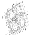
Fig. 2 is a perspective view of the plant cultivation container according to the present invention. -
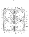
Fig. 3 is a plan view showing an action in the plant cultivation container ofFig. 2 . -
Fig. 4 is a vertical cross-sectional view taken along a feed-discharge channel of the plant cultivation container ofFig. 2 . -
Fig. 5 is a perspective view of a plant cultivation bed material used in the present invention. -
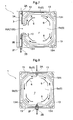
Fig. 6 is a plan view showing an action in the plant cultivation container according to another embodiment of the present invention. -
Fig. 7 is a plan view showing an action in the plant cultivation container according to still another embodiment. -
Fig. 8 is a plan view showing an action in the plant cultivation container according to still another embodiment. -
Fig. 9 is a plan view showing an action in the plant cultivation container according to still another embodiment. -
Fig. 10 is a perspective view of a specific portion ofFig. 9 . -
Fig. 11 is a perspective view of another specific portion ofFig. 9 . - Hereinbelow, embodiments of the present invention will be described with reference to the drawings.
Fig. 1 is one example of the plant cultivation device placeable outdoors, such as on a roof top of a building, and includes: a plurality ofplant cultivation containers 1 each integrally formed of resin; plantcultivation bed materials 20 each disposed in theplant cultivation container 1; and a feed-water equipment 30 for supplying the plant cultivation water to theplant cultivation containers 1. - As shown in
Fig. 2 , each of theplant cultivation containers 1 has an outer shape of an approximate square as a planar view. At a center of a plate-shaped first side member E1 constituting one side of theplant cultivation container 1, awater inlet 2A is provided which is for receiving the plant cultivation water into theplant cultivation container 1. At a center of a second side member E2 opposite to the first side member E1, awater outlet 2B is provided which is for discharging excessive plant cultivation water from theplant cultivation container 1.
An axis X connecting midpoints of the two side members E1,E2 extends at the center of theplant cultivation container 1 in parallel with remaining side members E3,E4, and a linear feed-discharge channel 3 runs along the axis X. Thewater inlet 2A and thewater outlet 2B are positioned at both ends of the feed-discharge channel 3, and a beak-shapedslice 2F projects nearly horizontally from thewater outlet 2B. - In
Fig. 2 , on each of a right side and a left side of the feed-discharge channel 3, two approximate square-shapedplant cultivation sections 4 are arranged along and in parallel with the feed-discharge channel 3. Four in total of theplant cultivation sections 4 collectively form theplant cultivation container 1 having an outer shape of an approximate square as a whole, as a planar view.
The plantcultivation bed material 20 is formed of a porous material having a function of supporting the plant while allowing growth of its root, and a function of absorbing and holding the plant cultivation water necessary for growth. As shown inFigs.1 and5 , herein, the plantcultivation bed material 20 includes: alower bed material 20A for absorbing the fed plant cultivation water; and anupper bed material 20B which is placed on thelower bed material 20A and supports a plant. In theupper bed material 20B, arecess 21 is formed which is for planting a seedling of, for example, flowering plant. The plant cultivation bed material 20 (20A, 20B) used herein is formed of a mixture of urethane, crushed wood chips and the like, and is configured to hold moisture and air in a balanced manner, nearly uniformly from top to bottom, and at the same time, to facilitate the holding of air necessary for the growth of the root. - As shown in
Figs.2 and3 , each of theplant cultivation sections 4 is provided with a single water reservoir container 5 (one example of water reservoir portion) for pooling the plant cultivation water. Therefore, the feed-discharge channel 3 serves a groove-shaped feed-discharge channel disposed next to one side of eachwater reservoir container 5, and the twowater reservoir containers 5 are arranged on the right and left sides of and next to the feed-discharge channel 3 so that they are opposed across the feed-discharge channel 3. Thewater reservoir container 5 has eight wall faces 5b extending obliquely upward from an outermost periphery of an approximate octagonalbottom face 5a, to form a mortar shape. Thewater reservoir container 5 is connected to the side members E1,E2,E3,E4 through only upper ends of the four wall faces 5b extending in approximate parallel with any of the four side members E1,E2,E3,E4 from among the eight wall faces 5b.
Four low plate-shapedprojections 6 stand upward at positions closer to the center by a predetermined distance from the outermost periphery of thebottom face 5a of thewater reservoir container 5. - An approximately octagonal area inside the plate-shaped
projection 6 forms a bedmaterial accommodation part 7 for placing thelower bed material 20A. One of roles of the plate-shapedprojection 6 is to fix thelower bed material 20A to a proper position at the center of thebottom face 5a in a proper posture, by fixing a lower end portion of thelower bed material 20A to the inside of the plate-shapedprojections 6 in a manner nearly fitted thereinto. - An outside of the plate-shaped
projection 6 forms a surrounding feed-water channel 8 surrounding an entire circumference of the lower end portion of thelower bed material 20A. In the surrounding feed-water channel 8, thelower bed material 20A is not present, and thus basically the plant cultivation water freely moves to and fro.
It should be noted that, as a planar view, theupper bed material 20B has a larger outer diameter than that of thelower bed material 20A, and when theupper bed material 20B is placed on thelower bed material 20A, an outer periphery of theupper bed material 20B is positioned so as to be nearly fitted into an inner face of the eightwall face 5b of thewater reservoir container 5.
Accordingly, beneath theupper bed material 20B, a tunnel-shaped water channel that surrounds an entire circumference of thelower bed material 20A is formed. - As shown in
Fig. 4 , in a intermediate portion in a water flow direction of the feed-discharge channel 3, there is formed asecond weir member 3D which divides the feed-discharge channel 3 into afirst channel 3A on an upstream side and asecond channel 3B on a downstream side, and pools the plant cultivation water to a predetermined depth in thefirst channel 3A.
In addition, as shown inFigs. 2 - 4 , between the feed-discharge channel 3 and thewater reservoir container 5, there is provided a plate-shapedpartition wall 10 for partitioning two regions. Thepartition wall 10 is provided with: afirst opening 10A for allowing thefirst channel 3A of the feed-discharge channel 3 to communicate with the surrounding feed-water channel 8 of theplant cultivation section 4 on the upstream side; and asecond opening 10B for allowing thesecond channel 3B of the feed-discharge channel 3 to communicate with the surrounding feed-water channel 8 of theplant cultivation section 4 on the downstream side, both openings formed in a shape of cut-out. Thesecond weir member 3D having a certain length extends linearly from a downstream end portion of thefirst opening 10A to an upstream end portion of thesecond opening 10B. - Between the
water reservoir container 5 on the upstream side and thewater reservoir container 5 on the downstream side which are disposed along and in parallel with the feed-discharge channel 3, aconnection opening 11 for allowing the plant cultivation water to move to and fro is formed, and in theconnection opening 11, athird weir member 11D is formed for pooling the plant cultivation water to a predetermined depth.
A part of each surrounding feed-water channel 8 is provided with afirst weir member 8D for controlling a circulation direction of the plant cultivation water entering the surrounding feed-water channel 8 from thewater inlet 2A through thefirst opening 10A or thesecond opening 10B. - The two
first weir members 8D provided in the surrounding feed-water channels 8 of thewater reservoir containers 5 on the upstream and downstream sides extend in parallel with the axis X, in the same manner in a front-rear direction across thethird weir member 11D, and are arranged symmetrically about thethird weir member 11D as a planar view.
Referring toFig. 3 , when the description is made with respect to only theplant cultivation sections 4 on the right side of the axis X, thefirst weir member 8D provided in the upstreamwater reservoir container 5 is configured so as to connect a portion near a downstream end portion of the plate-shapedprojection 6 located on a lower left side in the drawing with theclosest wall face 5b. Thefirst weir member 8D provided in the downstreamwater reservoir container 5 is configured so as to connect a portion near an upstream end portion of the plate-shapedprojection 6 located on an upper left side in the drawing with theclosest wall face 5b.
It should be noted that, the position of thefirst weir member 8D is not specifically limited, as long as the circulation of the plant cultivation water is controlled. For example, thefirst weir member 8D may be disposed at a position closer to thefirst opening 10A or thesecond opening 10B, than the position illustrated inFig. 3 . - On upper ends of respective four corners of each
plant cultivation section 4, respective approximatelytriangular flanges 13 extend horizontally so as to fill the four corners. Lower faces of therespective flanges 13 are configured to engage with four sides of an upper face of theupper bed material 20B, and thus function to hold theupper bed material 20B to a proper position.
In addition, in a case where a great number of theplant cultivation containers 1 are connected in four directions, a worker can walk along and on at least a part of theflanges 13 for the purpose of maintenance of the flowering plants during growth. The feed-discharge channel 3 may be used in a closed state in which the channel is closed with a removable rectangular lid (not shown).
In eachflange 13, an oval throughhole 13H extends in parallel with an oblique short side of thebottom face 5a. In addition, theflange 13 is positioned higher than a height level of an upper end of thewall face 5b of thewater reservoir container 5, and between theflange 13 and thewall face 5b, a gap is formed which extends in parallel with the throughhole 13H. Though these gaps and the throughholes 13H, a surface such as floor on which theplant cultivation container 1 is placed can be seen. -
Fig. 1 shows two types of connection caps 24, 25 for achieving the connection of theplant cultivation containers 1 to one another. Thecircular connection cap 24 is used for unifying the fourplant cultivation containers 1, while thesemicircular connection cap 25 is used for unifying the twoplant cultivation containers 1. In order to lock lower end portions or the like of the connection caps 24,25, each of the four corner portions of theplant cultivation container 1 has an engagement hole or engagement projection in a shape of a quadrant. - For example, when the four
plant cultivation containers 1 are arranged in a square shape as a whole, the four engagement holes are arranged to form a circle as a whole at the center of the square. By locking thecircular connection cap 24 along this circule, the fourplant cultivation containers 1 are unified. When the twoplant cultivation containers 1 are arranged in the front-rear direction or a lateral direction, the two engagement holes are arranged to form a single semicircle as a whole. By locking thesemicircular connection cap 25 along this semicircle, the twoplant cultivation containers 1 are unified. - As shown in
Fig. 4 , when theplant cultivation containers 1 are connected in the front-rear direction, i.e. connected in such a manner that the feed-discharge channels 3 are arranged in series, the connection is made in such a manner that theslice 2F provided on thewater outlet 2B of theplant cultivation container 1 on the upstream side in the flow direction of the plant cultivation water enters thewater inlet 2A of theplant cultivation container 1 on the downstream side.
A relationship in height of the weir members, the plate-shapedprojection 6 and theslice 2F, when theplant cultivation container 1 is placed on a horizontal plane, is set as follows:second weir member 3D >slice 2F >third weir member 11D =water inlet 2A > plate-shapedprojection 6 >first weir member 8D. - As shown in
Fig. 1 , each of theplant cultivation containers 1 can be fixed to a floor face or the like of a rooftop of a building.Fig. 1 illustrates a case where afastening tool 26 is used which includes abolt 28 standing on an upper face of abase plate 27. A head part of thebolt 28 is welded to thebase plate 27. Thebase plate 27 is fixed to a desired part of a floor face in advance with an adhesive, a double-stick tape, another anchor bolt (not shown) or the like, thebolt 28 is inserted into a fixing hole 14 formed in the center of the plant cultivation container 1 (corresponding to a part of thesecond weir member 3D), and then theplant cultivation container 1 is fixed to thefastening tool 26 by fastening anut 29 screwed on thebolt 28. - As shown in
Fig. 1 , the feed-water equipment 30 includes: piping 31 for supplying the plant cultivation water to thewater inlet 2A of theplant cultivation container 1 disposed most upstream; anelectromagnetic valve 32 disposed between waterworks and the piping 31; a moisture sensor S inserted into theupper bed material 20B positioned most downstream; and thecontroller 33 for switching ON and OFF of theelectromagnetic valve 32 based on detection result of the moisture sensor S. - Each of the side members E1,E2,E3,E4 includes: a main outer periphery fa linearly upward extending from a lowest part of the
plant cultivation container 1; a shoulder portion fb extending inwardly from an upper end of the main outer periphery fa; and an auxiliary outer periphery fc linearly upward extending from the shoulder portion fb. The auxiliary outer periphery fc is positioned slightly inward of the main outer periphery fa.
In other words, when theplant cultivation containers 1 are connected in the front-rear direction (the feed-discharge channels 3 are arranged in series), the main outer periphery fa of the first side member E1 of theplant cultivation container 1 and another main outer periphery fa of the second side member E2 of the adjacentplant cultivation container 1 are brought into contact with or arranged next to each other. On the other hand, when theplant cultivation containers 1 are connected in the lateral direction (the feed-discharge channels 3 are arranged in parallel), the main outer periphery fa of the third side member E3 of theplant cultivation container 1 and another main outer periphery fa of the fourth side member E4 of the adjacentplant cultivation container 1 are brought into contact with or arranged next to each other. - Therefore, when the two
plant cultivation containers 1 are connected, thewater reservoir containers 5 neighboring across the side members E1,E2 or the side members E3,E4 are arranged apart from each other at a distance twice as long as a width of the shoulder portion fb.
The distance twice as long as the width of the shoulder portion fb is set to a value approximately the same as a width of the feed-discharge channel 3 or the like that separates two adjacentwater reservoir containers 5 in the front-rear direction or the lateral direction in theplant cultivation container 1. Accordingly, when theplant cultivation containers 1 are connected in the front-rear direction or lateral direction, the adjacentupper bed materials 20B disposed in the respectiveplant cultivation sections 4 are arranged apart from each other at an approximately constant distance regardless of the arrangement directions, which distance is nearly the distance twice as long as the width of the shoulder portion fb. - Referring to
Fig. 3 , when the feed-water equipment 30 begins to supply the plant cultivation water to thewater inlet 2A of theplant cultivation container 1 disposed most upstream, first, the plant cultivation water enters thefirst channel 3A of the feed-discharge channel 3, hit thesecond weir member 3D, and is separated to right and left. Through the right and leftfirst openings 10A, the water enters the surrounding feed-water channels 8 (the water reservoir containers 5) of the right and left upstreamplant cultivation sections 4. The plant cultivation water that has entered the surrounding feed-water channel 8 flows through either or both of the upstream side or the downstream side of the channel in accordance with a degree of a slope where the container is placed. However, after the plant cultivation water flowing through the downstream side reaches thefirst weir member 8D disposed in the surrounding feed-water channel 8, the water flowing through the upstream side becomes predominant, flows clockwise around outer circumferences of thelower bed material 20A and the plate-shapedprojections 6 along the surrounding feed-water channel 8, and reaches thefirst weir member 8D, to thereby rapidly surround the entire circumference of thelower bed material 20A with the plant cultivation water. In this manner, the plate-shapedprojection 6 also serves as a guide member for guiding the plant cultivation water in a given circulation direction. Thelower bed material 20A immediately begins to absorb the plant cultivation water, but when the plant cultivation water is supplied at a rate above a speed of water absorption by thelower bed material 20A, the water overflows above thethird weir member 11D and moves from theconnection opening 11 to the downstreamplant cultivation section 4. - It should be noted that, in this embodiment, the four water reservoir containers 5 (water reservoir portion) is included in a single
plant cultivation container 1, but the two water reservoir containers 5 (water reservoir portion) provided in parallel with the axis X on the right or left side and connected with each other through theconnection opening 11 may be considered as a single water reservoir container 5 (water reservoir portion). Accordingly, theplant cultivation container 1 is considered as having a configuration in which the feed-discharge channel 3 for supplying the plant cultivation water from outside to the water reservoir container 5 (water reservoir portion) and discharging the plant cultivation water in the water reservoir container 5 (water reservoir portion) to outside is provided in communication with the surrounding feed-water channel 8. - The plant cultivation water that has entered the surrounding feed-
water channel 8 on the downstreamplant cultivation section 4 flows clockwise about the outer circumference of thelower bed material 20A and the plate-shapedprojections 6 along the surrounding feed-water channel 8 due to the presence of thefirst weir member 8D disposed on the downstream side of the channel, and reaches thefirst weir member 8D, to thereby rapidly surround the entire circumference of thelower bed material 20A with the plant cultivation water. A part of the plant cultivation water that has surrounded thelower bed material 20A enters thesecond channel 3B. Thelower bed material 20A immediately begins to absorb the plant cultivation water, but when the plant cultivation water is supplied from the upstreamplant cultivation section 4 at a rate above the speed of water absorption by thelower bed material 20A, the water overflows from theslice 2F of thewater outlet 2B and flows into thewater inlet 2A of the downstreamplant cultivation container 1.
Such an action of the plant cultivation water is performed nearly symmetrically in the right and leftplant cultivation sections 4 across the feed-discharge channel 3.
It should be noted that, acontroller 33 may be set in such a manner that the extra plant cultivation water is not discharged from theslice 2F of theplant cultivation container 1 disposed most downstream. Alternatively, thewater outlet 2B of theplant cultivation container 1 disposed most downstream may be closed with a special plug member. -
- <1> The
plant cultivation section 4 may not be necessarily used as four sections connected together, and as shown inFig. 6 , the configuration may include thewater reservoir container 5 formed of the singleplant cultivation section 4 disposed next to one side of the feed-discharge channel 3. The upstream end portion of thesecond weir member 3D is neighboring to the upstream side of the surrounding feed-water channel 8 of theplant cultivation section 4, and the downstream end portion of thesecond weir member 3D is neighboring to the downstream side of the surrounding feed-water channel 8 of theplant cultivation section 4. Therefore, thefirst opening 10A and thesecond opening 10B are arranged at a sufficient distance apart from each other. Herein, thefirst weir member 8D provided in theplant cultivation section 4 extends from the downstream end portion of the upstream plate-shapedprojection 6 to the upstream end portion of thepartition wall 10 in such a manner that it crosses the axis X. Therefore, the plant cultivation water that has entered the surrounding feed-water channel 8 from thefirst opening 10A circulates clockwise about the outer circumference of thelower bed material 20A from the beginning due to the presence of thefirst weir member 8D and reaches a portion around thesecond opening 10B. It should be noted that, also in the embodiment ofFig. 2 , thefirst weir member 8D provided in the upstreamplant cultivation section 4 may extends from the downstream end portion of the upstream plate-shapedprojection 6 to thewall face 5b forming thefirst opening 10A in such a manner that it crosses the axis X, like inFig. 6 . -
- <2> As shown in
Fig. 7 , thesecond weir member 3D may be omitted from the embodiment ofFig. 6 . In the embodiment ofFig. 7 , thesecond weir member 3D is omitted, only a single channel is present as the feed-discharge channel 3, and an entire length of the channel communicates with the surrounding feed-water channel 8. The plant cultivation water may not necessarily circulate clockwise in the surrounding feed-water channel 8 as shown in the drawing, but the effect is obtained in which the plant cultivation water that has entered the surrounding feed-water channel 8 surrounds the entire outer circumference of thelower bed material 20A, and excessive plant cultivation water is discharged from the surrounding feed-water channel 8 to the downstreamplant cultivation container 1. -
- <3> In the embodiment of
Fig. 7 , the feed-discharge channel 3 is arranged next to a side of thewater reservoir container 5, but the feed-discharge channel 3 may be included in thewater reservoir container 5, as shown inFig. 8 . In the embodiment ofFig. 8 , the surrounding feed-water channel 8 surrounding the entire circumference of the bed material accommodation part itself serves as the feed-discharge channel. -
- <4> The plant cultivation bed material may be a single plant cultivation bed material in which the
lower bed material 20A and theupper bed material 20B are integrally formed. -
- <5> The surface on which the plant cultivation container according to the present invention is placed is not limited to the inclined surface, but may be placed on a horizontal floor face or the ground. In addition, the configuration in use is not limited to a plurality of the plant cultivation container connected to one another, but a single plant cultivation container as-is may be used.
-
- <6> The feed-
water equipment 30 is not limited to the configuration described above, as long as the plant cultivation water can be appropriately supplied. For example, the equipment may not be connected to waterworks and water may be supplied from a feed-water tank. In addition, the control may not be performed based on the detection value of the sensor, but timings of water feed initiation and water feed termination may be automatically controlled using a timer set by a worker or the like. -
- <7> As shown in
Figs. 9 and 10(a) , at a position adjacent to thethird weir member 11D on the upstream or downstream side of thethird weir member 11D, a plate-shapedauxiliary weir 23 for minutely controlling a to-and-fro movement of the plant cultivation water between the upstreamwater reservoir container 5 and the downstreamwater reservoir container 5, may be additionally and removably provided as option member. Herein, for additionally attaching the plate-shapedauxiliary weir 23, a pair of engagingportions 12 are arranged adjacent to thethird weir member 11D on the downstream side of thethird weir member 11D. - The
third weir member 11D connects lower portions of a pair of end faces 5c formed in the wall faces 5b for providing the connection opening 11 (in this regard, thethird weir member 11D is the same as the embodiment shown inFig. 2 ). A pair of the engagingportions 12 are a pair of rib-shaped members formed on respective lower ends of a pair of the end faces 5c, provided next to thethird weir member 11D. Since the rib-shapedengaging portions 12 extend from a pair of the end faces 5c to a small degree, the engagingportion 12 alone does not have influence on the water flow. When the plate-shapedauxiliary weir 23 having a height above the height of thethird weir member 11D is inserted into a vertical groove formed between the rib-shapedengaging portions 12 and thethird weir member 11D, and a lower face of theauxiliary weir 23 is brought into close contact with bottom face of theplant cultivation container 1, the height of the weir that partitions theconnection opening 11 can be appropriately changed. - In other words, the height of the
third weir member 11D is set to a value suitable for a floor face with a relatively mild degree of the slope, and in a case where theplant cultivation container 1 is placed on the floor face with a steeper slope, an appropriate water feed function can be attained regardless of the degree of the slope, by inserting theauxiliary weir 23 having a height suitable for the degree of the slope. - It should be noted that, for example, when a width of the vertical groove formed between the rib-shaped
engaging portions 12 and thethird weir member 11D is set to a size approximately the same as a thickness of theauxiliary weir 23, and when theauxiliary weir 23 is configured in such a manner that the installedauxiliary weir 23 is brought into close contact with a face of thethird weir member 11D, as shown inFig. 10(b) , theauxiliary weir 23 can be appropriately moved upward or downward and fixed at a desired height, and thus it is not necessary to provide several types of theauxiliary weirs 23 that have different heights from one another. -
- <8> When the
plant cultivation container 1 is placed on the floor face with a relatively steep slope, in order to suppress deficiency of the pooled water in the downstreamwater reservoir container 5 as compared with the upstreamwater reservoir container 5, as shown inFigs. 9 and11 , thesecond opening 10B on the downstream side alone may be provided with aweir member 15 with a relatively low height. Alternatively, theweir member 15 may be provided as option member, which is press-engageable between the right and leftpartition walls 10 constituting thesecond opening 10B, and removable therefrom when unnecessary. In addition, several types of theweir members 15 that have different height from one another may be provided as option member. - The present invention is applicable as plant cultivation container including a water reservoir portion for pooling the plant cultivation water, the water reservoir portion having a bed material accommodation part for placing the water-absorbing plant cultivation bed material in the water reservoir portion, wherein there is no need to provide a special feed-water tube made of a porous material and the plant cultivation bed material can be permeated satisfactorily in a short time period.
-
- S
- Moisture sensor
- X
- Axis
- 1
- Plant cultivation container
- 2A
- Water inlet
- 2B
- Water outlet
- 2F
- Slice
- 3
- Feed-discharge channel
- 3A
- First channel
- 3B
- Second channel
- 3D
- Second weir member
- 4
- Plant cultivation section
- 5
- Water reservoir container (water reservoir portion)
- 7
- Bed material accommodation part
- 8
- Surrounding feed-water channel
- 8D
- First weir member
- 10
- Partition wall
- 10A
- First opening
- 10B
- Second opening
- 11
- Connection opening
- 11D
- Third weir member
- 12
- Engaging portion
- 20
- Plant cultivation bed material
- 20A
- Lower bed material
- 20B
- Upper bed material
- 23
- Auxiliary weir
Claims (9)
- A plant cultivation container comprising: a water reservoir portion for pooling plant cultivation water, the water reservoir portion having a bed material accommodation part for placing a water-absorbing plant cultivation bed material,
wherein
the water reservoir portion is provided with a surrounding feed-water channel that surrounds an entire circumference of the bed material accommodation part, and
a feed-discharge channel for supplying the plant cultivation water from outside to the water reservoir portion and for discharging the plant cultivation water in the water reservoir portion to outside is provided in communication with the surrounding feed-water channel. - The plant cultivation container according to claim 1, wherein the surrounding feed-water channel is provided with a first weir member for controlling a circulation direction of the plant cultivation water.
- The plant cultivation container according to claim 1 or 2, wherein the feed-discharge channel is in a shape of a groove disposed next to one side of the water reservoir portion.
- The plant cultivation container according to claim 3, further comprising: a second weir member for dividing the feed-discharge channel into a first channel on an upstream side and a second channel on a downstream side in a water flow direction; and a partition wall for partitioning the feed-discharge channel and the water reservoir portion,
wherein
in the partition wall, a first opening for allowing the first channel of the feed-discharge channel to communicate with an upstream side of the surrounding feed-water channel and a second opening for allowing the second channel of the feed-discharge channel to communicate with a downstream side of the surrounding feed-water channel are formed at a distance from each other. - The plant cultivation container according to claim 3 or 4, wherein the water reservoir portion is formed of two water reservoir portions arranged side by side so that the water reservoir portions are opposed across the feed-discharge channel.
- The plant cultivation container according to any one of claims 3 to 5, wherein a plurality of the water reservoir portions are arranged adjacent to each other along the feed-discharge channel, and between the adjacent water reservoir portions, a third weir member for pooling the plant cultivation water is provided.
- The plant cultivation container according to claim 6, further comprising: a second weir member for dividing the feed-discharge channel into a first channel on an upstream side and a second channel on a downstream side in a water flow direction; and a partition wall for partitioning the feed-discharge channel and the water reservoir portion,
wherein
in the partition wall, a first opening for allowing the first channel of the feed-discharge channel to communicate with the water reservoir portion on the upstream side and a second opening for allowing the second channel of the feed-discharge channel to communicate with the surrounding feed-water channel on the downstream side are formed. - The plant cultivation container according to claim 6 or 7, further comprising an engaging portion for additionally and removably attaching an auxiliary weir at a position adjacent to the third weir member on an upstream side or downstream side thereof.
- The plant cultivation container according to claim 7, wherein a weir member for pooling the plant cultivation water in the water reservoir portion on the downstream side is provided between the second opening and the second channel.
Applications Claiming Priority (2)
| Application Number | Priority Date | Filing Date | Title |
|---|---|---|---|
| JP2009272837 | 2009-11-30 | ||
| PCT/JP2010/071367 WO2011065566A1 (en) | 2009-11-30 | 2010-11-30 | Plant-growing container |
Publications (2)
| Publication Number | Publication Date |
|---|---|
| EP2508063A1 true EP2508063A1 (en) | 2012-10-10 |
| EP2508063A4 EP2508063A4 (en) | 2014-12-17 |
Family
ID=44066670
Family Applications (1)
| Application Number | Title | Priority Date | Filing Date |
|---|---|---|---|
| EP10833410.3A Withdrawn EP2508063A4 (en) | 2009-11-30 | 2010-11-30 | PFLANZENZUCHT CONTAINER |
Country Status (8)
| Country | Link |
|---|---|
| US (1) | US9655304B2 (en) |
| EP (1) | EP2508063A4 (en) |
| JP (1) | JP5851245B2 (en) |
| KR (1) | KR101418842B1 (en) |
| CN (1) | CN102124916B (en) |
| CA (1) | CA2785232C (en) |
| TW (1) | TWI451836B (en) |
| WO (1) | WO2011065566A1 (en) |
Cited By (6)
| Publication number | Priority date | Publication date | Assignee | Title |
|---|---|---|---|---|
| EP3006646A1 (en) | 2014-10-06 | 2016-04-13 | SOPREMA (Société par Actions Simplifiée Unipersonnelle) | Tile-on-pad covering system comprising at least one container |
| ES2607127A1 (en) * | 2016-12-20 | 2017-03-29 | Horticultura Hidropónica S.L. | System and procedure of irrigation for hydroponic crops (Machine-translation by Google Translate, not legally binding) |
| AU2019204555A1 (en) * | 2019-02-18 | 2020-09-03 | Lg Electronics Inc. | Apparatus for cultivating plants |
| US11191223B2 (en) | 2019-02-18 | 2021-12-07 | Lg Electronics Inc. | Apparatus for cultivating plants |
| US11778957B2 (en) | 2019-02-18 | 2023-10-10 | Lg Electronics Inc. | Apparatus for cultivating plants |
| US11778964B2 (en) | 2019-02-18 | 2023-10-10 | Lg Electronics Inc. | Apparatus for cultivating plants |
Families Citing this family (19)
| Publication number | Priority date | Publication date | Assignee | Title |
|---|---|---|---|---|
| JP5679254B2 (en) * | 2009-11-30 | 2015-03-04 | サントリーホールディングス株式会社 | Planting device and water supply control method |
| WO2013182920A1 (en) | 2012-06-06 | 2013-12-12 | Golovanov Sergey Aleksandrovich | Modular system for arranging plant compositions |
| JP5968197B2 (en) * | 2012-11-08 | 2016-08-10 | サントリーホールディングス株式会社 | Planting container |
| JP6138461B2 (en) * | 2012-11-19 | 2017-05-31 | サントリーホールディングス株式会社 | Planting equipment |
| CN103120115A (en) * | 2013-02-05 | 2013-05-29 | 上海交通大学 | Small-root-zone matrix soilless culture device |
| CN104663297A (en) * | 2015-03-29 | 2015-06-03 | 巫立斌 | Base for plant planting tank |
| USD922250S1 (en) * | 2016-07-01 | 2021-06-15 | Green Roof Outfitters, LLC | Green roof module |
| CN108353685A (en) * | 2018-04-20 | 2018-08-03 | 赖红邦 | Flower pot with automatic watering function |
| KR102650746B1 (en) * | 2018-11-12 | 2024-03-25 | 엘지전자 주식회사 | Plant cultivating apparatus |
| KR102901777B1 (en) | 2019-02-18 | 2025-12-19 | 엘지전자 주식회사 | Plants cultivation apparatus |
| KR102198477B1 (en) * | 2019-05-31 | 2021-01-06 | 주식회사 한국도시녹화 | Vegetation unit using artificial soil based on flyash and unit panel and greening system using the same |
| EP4129049B1 (en) * | 2020-03-31 | 2026-08-19 | LG Electronics Inc. | Plant cultivation device |
| KR102658001B1 (en) * | 2020-12-22 | 2024-04-17 | 엘지전자 주식회사 | Plant cultivation apparatus |
| KR102439961B1 (en) * | 2021-08-12 | 2022-09-07 | 아쿠아셀 주식회사 | Pre-planting type artificial wetland creation device with adjustable water flow |
| FR3128476B1 (en) * | 2021-10-21 | 2023-10-27 | Cactile | ROOF ELEMENT, ROOF COMPRISING SUCH A ROOF ELEMENT AND METHOD FOR INSTALLING SUCH A ROOF |
| US20260165258A1 (en) * | 2021-11-19 | 2026-06-18 | Kawada Industries, Inc. | Greening system and method of installing the same |
| USD1075558S1 (en) * | 2021-12-13 | 2025-05-20 | Lg Electronics Inc. | Pod for indoor plant cultivator |
| USD1075559S1 (en) * | 2021-12-13 | 2025-05-20 | Lg Electronics Inc. | Pod for indoor plant cultivator |
| FR3163531A1 (en) * | 2024-06-20 | 2025-12-26 | Soprema | Green roof tray, pre-cultivated module including such a tray and green roof system |
Family Cites Families (36)
| Publication number | Priority date | Publication date | Assignee | Title |
|---|---|---|---|---|
| JPS6337799Y2 (en) * | 1980-07-24 | 1988-10-05 | ||
| JPS619230A (en) * | 1984-06-25 | 1986-01-16 | 赤塚 尚彦 | Automatic irrigation apparatus |
| EP0204883B1 (en) * | 1985-01-24 | 1993-04-14 | Hans Steinbronn | Carrier plate for a plant substrate serving for turfing a roof |
| JPS62126916A (en) * | 1985-11-29 | 1987-06-09 | 日本鋼管株式会社 | crop cultivation unit |
| JPS6331724A (en) | 1986-07-25 | 1988-02-10 | Toyoda Gosei Co Ltd | Elastomer material automatic supplying device |
| JPH065724Y2 (en) * | 1986-08-13 | 1994-02-16 | 秀雄 清水 | Plant cultivation tool |
| JPS63105616A (en) * | 1986-10-23 | 1988-05-10 | 永松 睦雄 | Soil for vegetation of plant such as turf |
| US4887388A (en) * | 1988-10-19 | 1989-12-19 | Waltel Jr Joseph | Irrigation system for commercial plant cultivation |
| JPH0645436U (en) * | 1992-05-19 | 1994-06-21 | 邦司 山田 | Tank type flower pot water supply device |
| CA2073892A1 (en) * | 1992-07-15 | 1994-01-16 | Paul Houweling | Watering gutters |
| US5337517A (en) * | 1992-10-30 | 1994-08-16 | Envigro, Inc. | Transferable growing tray apparatus |
| JP3472361B2 (en) | 1994-10-21 | 2003-12-02 | 株式会社オーシマ・デザイン設計 | Greening automatic water supply system |
| JPH10150870A (en) * | 1996-11-20 | 1998-06-09 | Kubota Corp | Hydroponic cultivation pots and hydroponic equipment |
| JPH10178913A (en) * | 1996-12-27 | 1998-07-07 | Kaneya Sangyo Kk | Flowerpot storage case |
| JP3842397B2 (en) * | 1997-09-01 | 2006-11-08 | 岐阜プラスチック工業株式会社 | Outer frame structure of plant cultivation equipment |
| JPH11289876A (en) * | 1998-04-10 | 1999-10-26 | Kyodo Ky Tec Corp | Planting mat |
| JP4535471B2 (en) * | 1999-09-14 | 2010-09-01 | 共同カイテック株式会社 | Water supply system |
| JP4188513B2 (en) * | 1999-09-17 | 2008-11-26 | 陽 佐藤 | Nursery pot container |
| JP2001204259A (en) * | 2000-01-28 | 2001-07-31 | Mikado Ikushu Nojo:Kk | Bottom liquid absorption system and cultivation bed used for it |
| FR2851419B1 (en) * | 2003-02-25 | 2005-04-01 | Prm | WATER RESERVE DEVICE FOR ENGAZONNE SURFACE CULTURE |
| FR2884107B1 (en) * | 2005-04-07 | 2008-11-14 | Prm Soc Par Actions Simplifiee | LIQUID RESERVOIR DEVICE FOR CULTIVATING A SURFACE |
| JP2007000063A (en) | 2005-06-23 | 2007-01-11 | Noriaki Kunimune | Planting container for rooftop greening |
| SG131811A1 (en) * | 2005-10-25 | 2007-05-28 | Housing & Dev Board | A receptacle for use in a green roof system and a green roof system thereof |
| WO2007063815A1 (en) * | 2005-11-30 | 2007-06-07 | Suntory Limited | Plant cultivating unit and plant cultivating container |
| JP5142498B2 (en) * | 2006-08-14 | 2013-02-13 | 田島ルーフィング株式会社 | Planting equipment and planting structure for plants |
| KR101429206B1 (en) * | 2006-10-11 | 2014-08-14 | 산토리 홀딩스 가부시키가이샤 | Planting container |
| JP2008148560A (en) * | 2006-12-14 | 2008-07-03 | Aron Kasei Co Ltd | Planting unit for greening |
| TW200838415A (en) * | 2007-03-26 | 2008-10-01 | Chun-Fu Chen | Planting box set with water supply and water circulation system thereof |
| FR2917572B1 (en) * | 2007-06-19 | 2009-10-02 | M Plastic Sarl Ab | LIQUID RESERVOIR DEVICE FOR CULTIVATING A SURFACE |
| JP5474285B2 (en) * | 2007-08-21 | 2014-04-16 | サントリーホールディングス株式会社 | Planting container |
| JP2009165400A (en) * | 2008-01-16 | 2009-07-30 | Aron Kasei Co Ltd | Planting unit, planting unit for greening using the unit, and system thereof |
| FR2929632B1 (en) * | 2008-04-04 | 2010-12-31 | Sarl Le Prieure | DEVICE AND METHOD FOR VEGETALIZATION OF ROOFED ROOF |
| US20090260284A1 (en) * | 2008-04-21 | 2009-10-22 | Daniel Barbalho | Green roof tray |
| WO2009132439A1 (en) * | 2008-04-29 | 2009-11-05 | Bioroof Systems Inc. | Modular green roof system with biodegradable vegetation tray |
| USD644559S1 (en) | 2009-11-20 | 2011-09-06 | Suntory Holdings Limited | Plant cultivating container |
| USD644562S1 (en) | 2009-11-20 | 2011-09-06 | Suntory Holdings Limited | Plant cultivating bed |
-
2010
- 2010-11-29 TW TW099141222A patent/TWI451836B/en not_active IP Right Cessation
- 2010-11-30 KR KR1020127015552A patent/KR101418842B1/en not_active Expired - Fee Related
- 2010-11-30 WO PCT/JP2010/071367 patent/WO2011065566A1/en not_active Ceased
- 2010-11-30 EP EP10833410.3A patent/EP2508063A4/en not_active Withdrawn
- 2010-11-30 JP JP2011543364A patent/JP5851245B2/en not_active Expired - Fee Related
- 2010-11-30 CN CN2010105833418A patent/CN102124916B/en not_active Expired - Fee Related
- 2010-11-30 CA CA2785232A patent/CA2785232C/en not_active Expired - Fee Related
- 2010-11-30 US US13/511,492 patent/US9655304B2/en not_active Expired - Fee Related
Cited By (10)
| Publication number | Priority date | Publication date | Assignee | Title |
|---|---|---|---|---|
| EP3006646A1 (en) | 2014-10-06 | 2016-04-13 | SOPREMA (Société par Actions Simplifiée Unipersonnelle) | Tile-on-pad covering system comprising at least one container |
| ES2607127A1 (en) * | 2016-12-20 | 2017-03-29 | Horticultura Hidropónica S.L. | System and procedure of irrigation for hydroponic crops (Machine-translation by Google Translate, not legally binding) |
| WO2018115557A1 (en) * | 2016-12-20 | 2018-06-28 | Horticultura Hidropónica S.L. | Irrigation method and system for hydroponic crops |
| AU2019204555A1 (en) * | 2019-02-18 | 2020-09-03 | Lg Electronics Inc. | Apparatus for cultivating plants |
| US11191223B2 (en) | 2019-02-18 | 2021-12-07 | Lg Electronics Inc. | Apparatus for cultivating plants |
| US11382288B2 (en) | 2019-02-18 | 2022-07-12 | Lg Electronics Inc. | Apparatus for cultivating plants |
| US11778957B2 (en) | 2019-02-18 | 2023-10-10 | Lg Electronics Inc. | Apparatus for cultivating plants |
| US11778964B2 (en) | 2019-02-18 | 2023-10-10 | Lg Electronics Inc. | Apparatus for cultivating plants |
| US12329076B2 (en) | 2019-02-18 | 2025-06-17 | Lg Electronics Inc. | Apparatus for cultivating plants |
| US12532817B2 (en) | 2019-02-18 | 2026-01-27 | Lg Electronics Inc. | Apparatus for cultivating plants |
Also Published As
| Publication number | Publication date |
|---|---|
| US9655304B2 (en) | 2017-05-23 |
| KR20120095981A (en) | 2012-08-29 |
| JP5851245B2 (en) | 2016-02-03 |
| CN102124916B (en) | 2013-11-13 |
| HK1155903A1 (en) | 2012-06-01 |
| JPWO2011065566A1 (en) | 2013-04-18 |
| KR101418842B1 (en) | 2014-07-11 |
| TWI451836B (en) | 2014-09-11 |
| WO2011065566A1 (en) | 2011-06-03 |
| CA2785232A1 (en) | 2011-06-03 |
| TW201143603A (en) | 2011-12-16 |
| EP2508063A4 (en) | 2014-12-17 |
| CN102124916A (en) | 2011-07-20 |
| US20120297677A1 (en) | 2012-11-29 |
| CA2785232C (en) | 2015-01-06 |
Similar Documents
| Publication | Publication Date | Title |
|---|---|---|
| CA2785232C (en) | Plant cultivation container | |
| EP2572570B1 (en) | Planting container | |
| US10531615B2 (en) | Modular container and modular irrigation system | |
| CA2781948C (en) | Plant cultivation device and feed-water control method | |
| CN102548389B (en) | plant tray | |
| WO2011014124A1 (en) | A plant housing device | |
| JP2012517221A (en) | Apparatus and system for plant cultivation | |
| KR20150107908A (en) | A flower pot for wall-greening and the wall-greening system using the same | |
| KR20170028734A (en) | Flower pot assembly | |
| JP2012019714A (en) | Wall surface greening unit, and wall surface greening equipment using the same | |
| JP2009089691A (en) | Culture container and greening system | |
| ES2580853B1 (en) | IMPROVED IRRIGATION MODULE AND MODULAR IRRIGATION SYSTEM | |
| HK1155903B (en) | Plant-growing container | |
| JP2003102294A (en) | Water pipe holder | |
| HK1162850B (en) | Planting container | |
| CN205902571U (en) | Multimode three -dimensional greening plants container | |
| HK1172273B (en) | A plant tray | |
| ITPN960008A1 (en) | CONTAINER FOR VARIOUS KINDS OF CULTIVATION |
Legal Events
| Date | Code | Title | Description |
|---|---|---|---|
| PUAI | Public reference made under article 153(3) epc to a published international application that has entered the european phase |
Free format text: ORIGINAL CODE: 0009012 |
|
| 17P | Request for examination filed |
Effective date: 20120620 |
|
| AK | Designated contracting states |
Kind code of ref document: A1 Designated state(s): AL AT BE BG CH CY CZ DE DK EE ES FI FR GB GR HR HU IE IS IT LI LT LU LV MC MK MT NL NO PL PT RO RS SE SI SK SM TR |
|
| DAX | Request for extension of the european patent (deleted) | ||
| A4 | Supplementary search report drawn up and despatched |
Effective date: 20141118 |
|
| RIC1 | Information provided on ipc code assigned before grant |
Ipc: A01G 1/00 20060101ALI20141112BHEP Ipc: E04D 11/00 20060101ALI20141112BHEP Ipc: A01G 9/02 20060101AFI20141112BHEP Ipc: A01G 27/00 20060101ALI20141112BHEP Ipc: A01G 27/02 20060101ALI20141112BHEP |
|
| 17Q | First examination report despatched |
Effective date: 20160603 |
|
| GRAP | Despatch of communication of intention to grant a patent |
Free format text: ORIGINAL CODE: EPIDOSNIGR1 |
|
| RIC1 | Information provided on ipc code assigned before grant |
Ipc: A01G 9/033 20180101AFI20180115BHEP |
|
| INTG | Intention to grant announced |
Effective date: 20180201 |
|
| STAA | Information on the status of an ep patent application or granted ep patent |
Free format text: STATUS: THE APPLICATION IS DEEMED TO BE WITHDRAWN |
|
| 18D | Application deemed to be withdrawn |
Effective date: 20180612 |
|
| RIC1 | Information provided on ipc code assigned before grant |
Ipc: A01G 9/033 20180101AFI20180115BHEP |