EP2507712B1 - System for direct data transfer between memories of plurality of elements of this system - Google Patents
System for direct data transfer between memories of plurality of elements of this system Download PDFInfo
- Publication number
- EP2507712B1 EP2507712B1 EP10805264.8A EP10805264A EP2507712B1 EP 2507712 B1 EP2507712 B1 EP 2507712B1 EP 10805264 A EP10805264 A EP 10805264A EP 2507712 B1 EP2507712 B1 EP 2507712B1
- Authority
- EP
- European Patent Office
- Prior art keywords
- data
- command
- memory
- peripheral device
- peripheral
- Prior art date
- Legal status (The legal status is an assumption and is not a legal conclusion. Google has not performed a legal analysis and makes no representation as to the accuracy of the status listed.)
- Active
Links
- 230000015654 memory Effects 0.000 title claims description 120
- 238000012546 transfer Methods 0.000 title claims description 60
- 230000002093 peripheral effect Effects 0.000 claims description 111
- 230000000977 initiatory effect Effects 0.000 claims description 8
- 230000004044 response Effects 0.000 claims description 6
- 230000002776 aggregation Effects 0.000 claims description 5
- 238000004220 aggregation Methods 0.000 claims description 5
- 230000005540 biological transmission Effects 0.000 description 18
- 238000012545 processing Methods 0.000 description 10
- 241001080024 Telles Species 0.000 description 9
- 238000007792 addition Methods 0.000 description 8
- 230000006870 function Effects 0.000 description 7
- 238000004891 communication Methods 0.000 description 5
- 239000003999 initiator Substances 0.000 description 5
- 230000007246 mechanism Effects 0.000 description 4
- 238000000034 method Methods 0.000 description 3
- 230000004931 aggregating effect Effects 0.000 description 2
- 125000004122 cyclic group Chemical group 0.000 description 2
- 238000009792 diffusion process Methods 0.000 description 2
- 238000005457 optimization Methods 0.000 description 2
- 230000008569 process Effects 0.000 description 2
- 238000012360 testing method Methods 0.000 description 2
- 238000012795 verification Methods 0.000 description 2
- 230000004913 activation Effects 0.000 description 1
- 238000012550 audit Methods 0.000 description 1
- 230000006399 behavior Effects 0.000 description 1
- 230000000903 blocking effect Effects 0.000 description 1
- 230000009365 direct transmission Effects 0.000 description 1
- 230000009977 dual effect Effects 0.000 description 1
- 238000011156 evaluation Methods 0.000 description 1
- 230000004907 flux Effects 0.000 description 1
- 238000013507 mapping Methods 0.000 description 1
- 238000012986 modification Methods 0.000 description 1
- 230000004048 modification Effects 0.000 description 1
- 230000000737 periodic effect Effects 0.000 description 1
- 230000003068 static effect Effects 0.000 description 1
- 238000012800 visualization Methods 0.000 description 1
Images


Classifications
-
- G—PHYSICS
- G06—COMPUTING; CALCULATING OR COUNTING
- G06F—ELECTRIC DIGITAL DATA PROCESSING
- G06F13/00—Interconnection of, or transfer of information or other signals between, memories, input/output devices or central processing units
- G06F13/14—Handling requests for interconnection or transfer
- G06F13/20—Handling requests for interconnection or transfer for access to input/output bus
- G06F13/28—Handling requests for interconnection or transfer for access to input/output bus using burst mode transfer, e.g. direct memory access DMA, cycle steal
-
- G—PHYSICS
- G06—COMPUTING; CALCULATING OR COUNTING
- G06F—ELECTRIC DIGITAL DATA PROCESSING
- G06F13/00—Interconnection of, or transfer of information or other signals between, memories, input/output devices or central processing units
- G06F13/38—Information transfer, e.g. on bus
- G06F13/40—Bus structure
- G06F13/4004—Coupling between buses
- G06F13/4022—Coupling between buses using switching circuits, e.g. switching matrix, connection or expansion network
-
- Y—GENERAL TAGGING OF NEW TECHNOLOGICAL DEVELOPMENTS; GENERAL TAGGING OF CROSS-SECTIONAL TECHNOLOGIES SPANNING OVER SEVERAL SECTIONS OF THE IPC; TECHNICAL SUBJECTS COVERED BY FORMER USPC CROSS-REFERENCE ART COLLECTIONS [XRACs] AND DIGESTS
- Y02—TECHNOLOGIES OR APPLICATIONS FOR MITIGATION OR ADAPTATION AGAINST CLIMATE CHANGE
- Y02D—CLIMATE CHANGE MITIGATION TECHNOLOGIES IN INFORMATION AND COMMUNICATION TECHNOLOGIES [ICT], I.E. INFORMATION AND COMMUNICATION TECHNOLOGIES AIMING AT THE REDUCTION OF THEIR OWN ENERGY USE
- Y02D10/00—Energy efficient computing, e.g. low power processors, power management or thermal management
Definitions
- the present invention relates to the transfer of data between at least memory areas of a computer system and more particularly a system allowing direct data transfers between memories of several elements of this system including one or more peripheral devices.
- DMA type controllers ascronym for Direct Memory Access in English terminology.
- a peripheral device such as a network card or a hard disk interface can itself transfer data between a memory internal thereto and a central memory located outside the memory. it, without the intervention of the processor or processors, the latter being limited to transmitting a read or write command comprising a start address of the memory area to be transferred and the length of this zone.
- the data transfer can be realized from an internal memory to an external memory and vice versa.
- DMA controllers are especially used in multitask computing systems using fast peripheral devices so as not to cause blocking during data transfers. They behave as initiators of read or write requests to transfer data from an internal memory of a peripheral device to a central memory and vice versa.
- the DMA type controllers protect the internal memory of a peripheral device by preventing direct access thereto.
- the figure 1 schematically illustrates a computer system comprising two peripheral devices each equipped with a DMA type controller.
- the computer system 100 comprises an input / output bus 105 to which are connected a motherboard 110 incorporating one or more processors 115, a central memory 120 and network cards 125 and 130.
- the computer system 100 includes not only the hardware components represented but also software applications as well as firmware (called firmwares in English terminology) allowing the implementation of the system.
- the network card 125 comprises a DMA type controller 135 for exchanging data between the central memory 120 and the network interface 140 via the bus 105.
- the network card 130 comprises a DMA type controller 145 enabling exchanging data between the central memory 120 and the interface 150 via the bus 105.
- the DMA controller 135 when the network interface 140 receives data from the network, the DMA controller 135 initiates a write request to the memory 120 for transferring the received data stored locally in a buffer (not shown) . Similarly, when the DMA controller 135 receives a read request from a processor 115 for transmitting data over the network, it initiates a read request to read data in the memory 120 and transfer it to the interface 140.
- the DMA controller 145 makes it possible to exchange data between the memory 120 and a network to which the card 130 is connected.
- the object of the invention is therefore, in particular, to improve systems implementing direct memory access controllers to enable direct data transfers between memories of several elements of this system, in particular between memory memories. several peripheral devices.
- the system according to the invention thus makes it possible to carry out direct data transfers between memories of several elements of the system, including one or more peripheral devices, in order to reduce the amount of central memory used in the computer system, to unload the central processor of some data transfer tasks and reduce latency due to read / write operations.
- the system also makes it possible to meet equipment redundancy requirements, particularly in areas such as telecom or finance that use equipment type 5-9, that is to say equipment whose reliability calculated is 99.99999%.
- the system according to the invention also makes it possible to multiply the performances of systems by aggregating data flows, for example towards graphic devices, in particular in the HPC domain and the visualization, where calculation flows can converge towards graphic memories. to allow their treatment.
- said at least one first device comprises means for performing at least one operation on at least one of data received from said plurality of elements in response to said at least one command.
- the system according to the invention thus makes it possible to process certain data during their transfer for optimization purposes. These operations are, for example, logical operations, mathematical operations, sort operations, coding operations or aggregation operations.
- said means for performing said at least one operation comprise means for identifying said at least one operation according to at least one of data received from said plurality of elements in response to said at least one command to identify simply the operation or operations to be performed.
- At least one element of said plurality of elements comprises a central memory of said computer system.
- the system according to the invention thus allows a direct transfer of data simultaneously to or from the central memory as well as to or from one or more peripheral devices.
- Said at least one second peripheral device furthermore preferably comprises means for checking the validity of said at least part of said at least one command in order to protect the memory of said at least one second device against unauthorized accesses.
- control means comprise means for comparing an identifier of the transmitter of said at least one direct access command with at least one predetermined identifier.
- said control means comprise means for comparing an identifier of the transmitter of said at least one direct access command with at least one predetermined identifier.
- control means comprise means for comparing said zone of a memory of said second peripheral device with at least one predetermined memory zone.
- said means of said at least one second device for transmitting said at least one direct access command received to a component of said second peripheral device comprise means for performing at least one operation on at least one piece of data received.
- said at least one first peripheral device further comprises means for identifying said at least one second peripheral device and means for transmitting a direct access command to an area of a memory of said second device when the memory targeted by the direct access command from said initiation means belongs to said at least one second peripheral device.
- Said at least one first peripheral device can thus identify said at least one second peripheral device and initiate a direct transfer of data between a memory of said at least one first peripheral device and at least one memory of said at least one second peripheral device.
- the invention aims to enable the direct transmission of data between peripheral device memories provided with DMA type controllers without the need for writing steps followed by reading steps in a central memory.
- the invention makes it possible to implement a dialogue mechanism between DMA type controllers enabling them to carry out transactions for which a DMA type controller is the initiator and at least one other controller.
- DMA type behaves as a target while performing the final part of the data transfer to the inside of the peripheral device considered.
- data received by the network interface 140 of the network card 125 can be transferred directly to the interface 150 of the card 130 without using the central memory 120.
- peripheral devices In particular, direct communication between several peripheral devices has many advantages in the context of high-performance scientific computing, in particular between graphics cards or GPUs ( Graphics Processing Units ) and Infiniband cards, between Infiniband cards and Ethernet cards. and between Infiniband cards.
- graphics cards or GPUs Graphics Processing Units
- Infiniband cards between Infiniband cards and Ethernet cards.
- Infiniband cards between Infiniband cards.
- the figure 2 schematically illustrates certain elements of a computer system 200 in which the invention can be implemented.
- the system here comprises a central memory 205 connected to a system bus 210 called host CPU bus which is also connected to the bus controller 215.
- the latter is intended in particular to convert and transfer information from the system bus 210 to a peripheral bus 220.
- the bus controller 215 includes a system bus interface 225, a data interface 230, and a peripheral bus interface 235.
- the computer system 200 further comprises two peripheral devices 240-1 and 240-2 connected to the peripheral bus 220.
- the peripheral device 240-1 is here a network card, for example an Ethernet card. It comprises a peripheral bus interface 245-1 and an associated processing unit 250-1 for processing the data packets exchanged via this peripheral bus interface. It further comprises a network interface 255 and an associated processing unit 260 for processing the data packets exchanged via this network interface. Furthermore, the peripheral device 240-1 comprises a computing unit 265 (or CPU, acronym for Central Processing Unit in English terminology) and a local memory 270, for example of SRAM (acronym for Static Random Access Memory in terminology Anglo-Saxon).
- a computing unit 265 or CPU, acronym for Central Processing Unit in English terminology
- SRAM acronym for Static Random Access Memory in terminology Anglo-Saxon
- the peripheral device 240-2 here a graphics card, comprises a peripheral bus interface 245-2 and a communication unit. associated processing 250-2 for processing the data packets exchanged via this peripheral bus interface.
- This device further comprises a plurality of calculation units 275-1 to 275-n each comprising a shared memory, a local memory and an elementary calculation unit.
- This device also comprises memories 280 common to all the calculation units, for example a global memory and a texture memory.
- the interfaces 245-1 and 245-2 incorporate a DMA type controller allowing direct data transfers between the central memory 205 via the bus controller 215 and an internal memory of the peripheral devices 240-1 and 240-2 and vice versa.
- DMA type controllers also include functions for directly transferring data between internal memories of these devices.
- DMA type controllers here include identification, declaration, configuration and control functions.
- the figure 3 illustrates schematically an example of a sequence of phases implemented in such a DMA type controller of a particular peripheral device. It is observed here that the phases represented on the figure 3 are not necessarily executed sequentially and may be executed in a different order than the one shown. In particular, the control phase can follow the registration phase.
- This phase can also be used to identify other peripheral devices connected to the same bus as the device in question, in particular devices comprising a DMA type controller according to the invention, in order to establish the list of peripheral devices with which the device considered can exchange data directly.
- phase 305 the device's DMA controller can initiate a memory zone declaration phase (phase 305).
- a function implemented in this phase aims in particular the declaration of the internal memory areas of the device in which other devices can read and / or write data, possibly under certain conditions.
- such a declaration is made to the common directory used to identify the peripheral devices connected to the same bus.
- the device may be configured to allow direct data transfer to or from other peripheral devices, i.e. to set data transfer rules.
- an evaluation step is advantageously implemented in a test period to evaluate the compatibility, particularly in terms of services and speed, of the device in question with other peripheral devices connected thereto.
- This phase also aims to create primitives for transfer in point-to-point mode by specifying the implemented devices, the areas of memory concerned and any data transmission parameters such as security and integrity control. It is observed here that the creation of primitives relates to the definition of read command and / or write but not their execution which is performed when conditions are met for example when data is written in internal memory or on request a user or an application.
- such a primitive can aim, with reference to the device 240-2 of the figure 2 , a write command of data from a shared memory of a computing unit 275-i to the local memory 270 of the device 240-1 (arrow 290). It can also be a command to read data from a buffer of the processing unit 260 of the device 240-1 to a memory 280 (arrow 285).
- the source and destination indications comprise the identifiers of the peripheral devices and memories considered as well as the target memory areas
- the length indicates the quantity of data to be transferred and the parameters concern the parameters to be used linked, for example, to the security, control of the data and execution of the command corresponding to the primitive.
- Primitives can also be created for the transmission of data in a multicast or broadcast collective mode which makes it possible to transfer data from a common source to several different devices as described below, in particular with reference to the figure 6 . Such a transfer mode is particularly useful when devices are duplicated to increase the reliability of the computer system.
- They may also include operations for grouping or unbundling data from or to memories of several peripheral devices to improve the performance of the computer system.
- Such operations can be considered as extensions of operations known as scatter and gather in English terminology according to which DMA controllers are able to group data from a memory to make a single exchange of a large amount of data.
- the execution of the commands corresponding to these primitives can be explicit (according to commands of the users or the kernel of the operating system), predetermined according to events (for example a data item can be the subject of a write command during its reception in memory) or periodic (the transfers are planned, that is to say that the contents of the memory is transferred, in whole or in part, according to determined time cycles).
- phase 315 a control phase can be implemented (phase 315) to allow a user to access the peripheral device.
- This access is preferably carried out through an interface. It allows here to obtain the version and the capacities of a device as well as to configure it. It also makes it possible to declare areas of an internal memory of the device accessible to other devices and / or to define rules on such areas of memory to indicate, for example, who can access these areas with which operations and according to which modes of transfer.
- the figure 4 schematically illustrates certain steps implemented in a DMA controller according to the invention for directly transferring data between several peripheral devices.
- a control of the received command is preferably performed (step 405).
- Such a control is intended in particular to protect the internal memory of the device having received the order. As indicated above, such a control can particularly target the initiator of the order and the memory area being the subject of the order.
- a test is then performed (step 410) to determine if the command is valid, that is to say here if the initiator of the command has the right to access the internal memory of the device having received the command and more particularly to the memory area specified in the command.
- the command is not valid, the command is rejected. An error message can then be sent to the initiator of the request (not shown). If, on the contrary, the command is valid, it is transmitted to another component of the device comprising the DMA controller having received the command (step 415), typically to a memory controller. The command is then executed in a standard way.
- the DMA type controller when it receives a data transfer activation notification (step 420), it executes the corresponding command in a standard manner.
- the data transfer enable notification can be received from a component of the device comprising the DMA controller, for example from a network interface, or from an external element, in particular processors of the central system of the system. computer science. It is observed that the transfer can aim here a read or write command from or to the central memory of the computer system but also from or to one or more peripheral devices which then implement steps similar to the steps 400 to 415 described previously.
- the DMA type controller here has a dual function of conventional DMA (steps 420 and 425) and bridge controller for transferring control of an external peripheral device to an internal component of the peripheral device comprising the DMA type controller which thus simulates a behavior of a memory controller vis-à-vis the external peripheral device (steps 400 to 415).
- the DMA type controllers adapted to implement the invention can be used for collective transfers, that is to say multipoint data transfers.
- the figure 5 illustrates a computer system 500 adapted to implement direct data transfers in multipoint mode.
- the computer system 500 here comprises processors 505 and a central memory 510 connected by a system bus 515.
- the system 500 further comprises a bus switch 520 also connected to the system bus 515 and a plurality of peripheral devices 525-1 to 525-n.
- the bus switch 520 is, for example, a PCI-E switch which is connected to the 525-1 to 525-n devices in point-to-point mode, independently, in a two-way link (called full-duplex in English terminology). Saxon), assigning bus widths based on the exchanges initiated by the DMA controllers of the peripheral devices.
- PCI-SIG provides in one specification the possibility of doing multicast PCI-E exchanges by implementing a suitable protocol in the DMA controller of a PCI-E switch to allow direct data transfers between the central memory and peripheral devices grouped in the form of a multicast group (or multicast group in English terminology).
- PCI-E switches that include up to 4 DMA controllers for direct data transfer according to descriptors specifically dedicated to multicast exchange. These descriptors indicate a common source for each of the multicast type controllers that target different targets, thus allowing multiple exchanges. These descriptors can also indicate whether interrupts should be generated for each DMA type controller or only at the end of the multicast transfer.
- Such switches can be used to implement the invention as previously described and thus allow the direct transfer of data between peripheral devices grouped in the form of a multicast group, each of these devices comprising a DMA type controller implementing the functions. previously described.
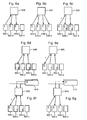
- the peripheral devices shown 600-1 to 600-4 each include a DMA type controller in accordance with the specifications described above. Each of these devices is here connected to a switch 605 adapted to manage collective transfers (multicast and broadcast).
- the figure 6a illustrates a multicast transmission of the device 600-1 to the devices 600-2 and 600-3.
- the data broadcast is thus carried out from a source to several targets of the multicast group to which the device 600-1 belongs. This is a communication type 1 to n initiated by the device comprising the transferred data.
- the figure 6b illustrates a broadcast type transmission from device 600-1 to devices 600-2, 600-3 and 600-4.
- the data broadcast is thus carried out from a source to all the targets of the multicast group to which the device 600-1 belongs. This is a type 1 communication to all initiated by the device comprising the transferred data.
- the Figure 6c illustrates a multicast type transmission calculated from the device 600-1 to the devices 600-2, 600-3 and 600-4.
- the data broadcast is thus carried out from a source to all the targets of the multicast group to which the device 600-1 belongs.
- an operation is performed on the transferred data, for example a logical operation such as "or", "and” or "exclusive", a mathematical operation such as an addition or a multiplication or an operation defined by the device such as a sort of data or their encryption.
- the operation performed here is an addition between the transferred data and a data present in the target device.
- the transmission is initiated by the device comprising the transferred data.
- the figure 6d illustrates a data aggregation type transmission of the devices 600-2 and 600-3 to the device 600-1. It is an operation that allows, from several sources, to transmit data to one or more targets by aggregating the transmitted data. The transmission is initiated by the device receiving the transferred data.
- the figure 6e illustrates a computationally aggregated data transmission of devices 600-2 and 600-3 to the device 600-1. It is an operation that allows, from several sources, to transmit data to a target by performing a calculation on the transmitted data. This is an addition between the data received from the sources used. The transmission is initiated by the device receiving the transferred data. Naturally other types of operations can be implemented.
- the figure 6f illustrates a computationally aggregated data transmission of the devices 600-2 and 600-3 and the central memory 610 to the device 600-1. This is an operation that allows, from several sources, to transmit data to a target by performing a calculation on the transmitted data. This is an addition between the data received from the sources used. The transmission is initiated by the device receiving the transferred data. Other types of operations can also be implemented.
- the figure 6g illustrates a multicast transmission of the device 600-1 to the devices 600-2 and 600-3 and the central memory 610.
- the data broadcast is thus carried out from a source to several targets of the multicast group to which the device belongs 600-1. This is a type 1 to n communication.
- the transmission is initiated by the device comprising the transferred data.
- the choice of the operation to be performed depends on some of the data received in response to a data read command.
- Direct data transfers between several peripheral devices can be implemented using collective transfer primitives determined in at least one of the peripheral devices.
- This implementation is similar to that described above. It includes phases of identification, declaration, configuration and control.
- the parameters of the collective transfer primitives are preferably similar to those of the primitives used to perform a direct transfer of data between memories of two peripheral devices as previously described. However, they also include specific characteristics related in particular to data combining operations.
- the device 600-1 waits to receive the transferred data and then performs the operation specified in the primitive.
- the step 425 described above then comprises a step for initiating the direct memory access control of other devices, a synchronization step for obtaining the expected data and a step for executing the operations specified in the primitive related to the transfer activated.
Description
La présente invention concerne le transfert de données entre au moins des zones de mémoires d'un système informatique et plus particulièrement un système autorisant des transferts directs de données entre des mémoires de plusieurs éléments de ce système dont un ou plusieurs dispositifs périphériques.The present invention relates to the transfer of data between at least memory areas of a computer system and more particularly a system allowing direct data transfers between memories of several elements of this system including one or more peripheral devices.
Les systèmes informatiques modernes intègrent fréquemment des mécanismes d'accès direct à une mémoire centrale par des systèmes d'entrée/sortie aussi appelés dispositifs périphériques. Ces mécanismes sont communément appelés des contrôleurs de type DMA (sigle de Direct Memory Access en terminologie anglo-saxonne).Modern computer systems frequently incorporate mechanisms for direct access to a central memory by input / output systems also called peripheral devices. These mechanisms are commonly called DMA type controllers (acronym for Direct Memory Access in English terminology).
Selon ce mode de transmission de données, un dispositif périphérique telle qu'une carte réseau ou une interface de disque dur peut effectuer lui-même un transfert des données entre une mémoire interne à celui-ci et une mémoire centrale située à l'extérieur de celui-ci, sans l'intervention du ou des processeurs, ces derniers se limitant à transmettre une commande de lecture ou d'écriture comprenant une adresse de début de la zone mémoire à transférer et la longueur de cette zone. Le transfert de données peut être réalisé d'une mémoire interne vers une mémoire externe et inversement.According to this data transmission mode, a peripheral device such as a network card or a hard disk interface can itself transfer data between a memory internal thereto and a central memory located outside the memory. it, without the intervention of the processor or processors, the latter being limited to transmitting a read or write command comprising a start address of the memory area to be transferred and the length of this zone. The data transfer can be realized from an internal memory to an external memory and vice versa.
Les contrôleurs de type DMA sont notamment utilisés dans les systèmes informatiques multitâches utilisant des dispositifs périphériques rapides afin de ne pas entraîner de blocage pendant les transferts de données. Ils se comportent comme des initiateurs de requêtes de lecture ou d'écriture pour transférer des données d'une mémoire interne d'un dispositif périphérique vers une mémoire centrale et inversement.DMA controllers are especially used in multitask computing systems using fast peripheral devices so as not to cause blocking during data transfers. They behave as initiators of read or write requests to transfer data from an internal memory of a peripheral device to a central memory and vice versa.
En outre, les contrôleurs de type DMA permettent de protéger la mémoire interne d'un dispositif périphérique en empêchant un accès direct à celle-ci.In addition, the DMA type controllers protect the internal memory of a peripheral device by preventing direct access thereto.
La
Comme illustré, le système informatique 100 comprend un bus d'entrée/sortie 105 auquel sont reliées une carte mère 110 intégrant un ou plusieurs processeurs 115, une mémoire centrale 120 et des cartes réseau 125 et 130. Bien qu'illustré de façon simplifiée sur la
Ainsi, par exemple, lorsque l'interface réseau 140 reçoit des données depuis le réseau, le contrôleur de type DMA 135 initie une requête d'écriture dans la mémoire 120 pour y transférer les données reçues mémorisées localement dans une mémoire tampon (non représentée). De façon similaire, lorsque le contrôleur de type DMA 135 reçoit une requête de lecture d'un processeur 115 pour transmettre des données via le réseau, il initie une requête de lecture pour lire des données dans la mémoire 120 et les transférer à l'interface 140.Thus, for example, when the
De même, le contrôleur de type DMA 145 permet d'échanger des données entre la mémoire 120 et un réseau auquel est reliée la carte 130.Likewise, the
Cependant, alors que les contrôleurs de type DMA ont prouvé leur efficacité dans de nombreuses architectures, il existe un besoin constant d'améliorer les performances des systèmes informatiques, en particulier des systèmes informatiques de type HPC (sigle d'High-performance computing en terminologie anglo-saxonne).However, while DMA controllers have proven their effectiveness in many architectures, there is a continuing need to improve the performance of computer systems, particularly HPC-based computer systems ( High-Performance Computing in terminology). Anglo-Saxon).
L'invention a ainsi pour objet, en particulier, d'améliorer les systèmes mettant en oeuvre des contrôleurs d'accès direct à une mémoire pour permettre des transferts directs de données entre des mémoires de plusieurs éléments de ce système, notamment entre des mémoires de plusieurs dispositifs périphériques.The object of the invention is therefore, in particular, to improve systems implementing direct memory access controllers to enable direct data transfers between memories of several elements of this system, in particular between memory memories. several peripheral devices.
L'invention a ainsi pour objet un système informatique comprenant une pluralité de dispositifs périphériques et au moins un commutateur connecté à chaque dispositif de ladite pluralité de dispositifs périphériques, ledit commutateur comprenant des moyens pour transférer une commande à une pluralité d'éléments dudit système informatique, dans lequel,
- au moins un dispositif de ladite pluralité de dispositifs périphériques, appelé au moins un premier dispositif périphérique, comprend des moyens pour initier au moins une commande d'accès direct à une pluralité de zones de mémoire, chacune desdites zones de mémoire étant associée à un élément distinct de ladite pluralité d'éléments ;
- ledit commutateur comprend des moyens pour transmettre au moins une partie de ladite au moins une commande d'accès directe à chaque élément de ladite pluralité d'éléments ;
- au moins un élément de ladite pluralité d'éléments consiste en au moins un dispositif de ladite pluralité de dispositifs périphériques, appelé au moins un second dispositif périphérique, ledit au moins un second dispositif périphérique comprenant les moyens suivants ;
- ○ moyens pour recevoir au moins une commande d'accès direct à une zone d'une mémoire dudit second dispositif périphérique, ladite commande étant reçue dudit au moins un premier dispositif périphérique via ledit commutateur ; et,
- o moyens pour transmettre ladite au moins une commande d'accès direct reçue à un composant dudit second dispositif périphérique,
- at least one of said plurality of peripheral devices, called at least one first peripheral device, comprises means for initiating at least one direct access command to a plurality of memory areas, each of said memory areas being associated with an element distinct from said plurality of elements;
- said switch comprises means for transmitting at least a portion of said at least one direct access command to each of said plurality of elements;
- at least one of said plurality of elements consists of at least one of said plurality of peripheral devices, called at least one second peripheral device, said at least one second peripheral device comprising the following means;
- Means for receiving at least one command for direct access to an area of a memory of said second peripheral device, said command being received from said at least one first peripheral device via said switch; and,
- means for transmitting said at least one direct access command received to a component of said second peripheral device,
Le système selon l'invention permet ainsi d'effectuer des transferts directs de données entre des mémoires de plusieurs éléments du système, dont un ou plusieurs dispositifs périphériques, afin, de réduire la quantité de mémoire centrale utilisée dans le système informatique, de décharger le processeur central de certaines tâches de transfert de données et de réduire la latence due aux opérations de lecture/écriture. Le système permet en outre de répondre à des besoins de redondance d'équipements, notamment dans des domaines tels que les télécoms ou la finance qui utilisent des équipements de type 5-9, c'est-à-dire des équipements dont la fiabilité calculée est de 99.99999%. Le système selon l'invention permet en outre de multiplier les performances de systèmes en agrégeant des flux de données, par exemple vers des dispositifs graphiques, en particulier dans le domaine HPC et la visualisation, où des flux de calculs peuvent converger vers des mémoires graphiques pour permettre leur traitement.The system according to the invention thus makes it possible to carry out direct data transfers between memories of several elements of the system, including one or more peripheral devices, in order to reduce the amount of central memory used in the computer system, to unload the central processor of some data transfer tasks and reduce latency due to read / write operations. The system also makes it possible to meet equipment redundancy requirements, particularly in areas such as telecom or finance that use equipment type 5-9, that is to say equipment whose reliability calculated is 99.99999%. The system according to the invention also makes it possible to multiply the performances of systems by aggregating data flows, for example towards graphic devices, in particular in the HPC domain and the visualization, where calculation flows can converge towards graphic memories. to allow their treatment.
Selon un mode de réalisation particulier, ledit au moins un premier dispositif comprend des moyens pour effectuer au moins une opération sur au moins une donnée parmi des données reçues de ladite pluralité d'éléments en réponse à la dite au moins une commande. Le système selon l'invention permet ainsi de traiter certaines données lors de leur transfert à des fins d'optimisation. Ces opérations sont, par exemple, des opérations logiques, des opérations mathématiques, des opérations de tri, des opérations de codage ou des opérations d'agrégation.According to a particular embodiment, said at least one first device comprises means for performing at least one operation on at least one of data received from said plurality of elements in response to said at least one command. The system according to the invention thus makes it possible to process certain data during their transfer for optimization purposes. These operations are, for example, logical operations, mathematical operations, sort operations, coding operations or aggregation operations.
De façon avantageuse, lesdits moyens pour effectuer ladite au moins une opération comprennent des moyens pour identifier ladite au moins une opération selon au moins une donnée parmi des données reçues de ladite pluralité d'éléments en réponse à la dite au moins une commande pour identifier simplement la ou les opérations à effectuer.Advantageously, said means for performing said at least one operation comprise means for identifying said at least one operation according to at least one of data received from said plurality of elements in response to said at least one command to identify simply the operation or operations to be performed.
Toujours selon un mode de réalisation particulier, au moins un élément de ladite pluralité d'éléments comprend une mémoire centrale dudit système informatique. Le système selon l'invention permet ainsi un transfert direct de données simultanément vers ou depuis la mémoire centrale ainsi que vers ou depuis un ou plusieurs dispositifs périphériques.Still according to a particular embodiment, at least one element of said plurality of elements comprises a central memory of said computer system. The system according to the invention thus allows a direct transfer of data simultaneously to or from the central memory as well as to or from one or more peripheral devices.
Ledit au moins un second dispositif périphérique comprend en outre, de préférence, des moyens pour contrôler la validité de ladite au moins une partie de ladite au moins une commande afin de protéger la mémoire dudit au moins un second dispositif contre des accès non autorisés.Said at least one second peripheral device furthermore preferably comprises means for checking the validity of said at least part of said at least one command in order to protect the memory of said at least one second device against unauthorized accesses.
De façon avantageuse, lesdits moyens de contrôle comprennent des moyens pour comparer un identifiant de l'émetteur de ladite au moins une commande d'accès direct avec au moins un identifiant prédéterminé. Ainsi, seuls les dispositifs périphériques autorisés peuvent accéder directement à une mémoire dudit au moins un second dispositif périphérique.Advantageously, said control means comprise means for comparing an identifier of the transmitter of said at least one direct access command with at least one predetermined identifier. Thus, only the authorized peripheral devices can directly access a memory of said at least one second peripheral device.
Toujours de façon avantageuse, lesdits moyens de contrôle comprennent des moyens pour comparer ladite zone d'une mémoire dudit second dispositif périphérique avec au moins une zone mémoire prédéterminée. Ainsi, il est possible de protéger des zones de mémoire dudit au moins un second dispositif périphérique afin qu'aucun ou que seulement certains dispositifs périphériques puissent y accéder.Still advantageously, said control means comprise means for comparing said zone of a memory of said second peripheral device with at least one predetermined memory zone. Thus, it is possible to protect memory areas of the at least one second peripheral device so that no or only certain peripheral devices can access it.
Selon un mode de réalisation particulier, lesdits moyens dudit au moins un second dispositif pour transmettre ladite au moins une commande d'accès direct reçue à un composant dudit second dispositif périphérique comprennent des moyens pour effectuer au moins une opération sur au moins une donnée reçue. Le système selon l'invention permet ainsi de traiter certaines données lors de leur transfert à des fins d'optimisation.According to a particular embodiment, said means of said at least one second device for transmitting said at least one direct access command received to a component of said second peripheral device comprise means for performing at least one operation on at least one piece of data received. The system according to the invention thus makes it possible to process certain data during their transfer for optimization purposes.
Toujours selon un mode de réalisation particulier, ledit au moins un premier dispositif périphérique comprend en outre des moyens pour identifier ledit au moins un second dispositif périphérique et des moyens pour transmettre une commande d'accès direct à une zone d'une mémoire dudit second dispositif lorsque la mémoire visée par la commande d'accès direct issue desdits moyens d'initiation appartient audit au moins un second dispositif périphérique. Ledit au moins un premier dispositif périphérique peut ainsi identifier ledit au moins un second dispositif périphérique et initier un transfert direct de données entre une mémoire dudit au moins un premier dispositif périphérique et au moins une mémoire dudit au moins un second dispositif périphérique.Still according to a particular embodiment, said at least one first peripheral device further comprises means for identifying said at least one second peripheral device and means for transmitting a direct access command to an area of a memory of said second device when the memory targeted by the direct access command from said initiation means belongs to said at least one second peripheral device. Said at least one first peripheral device can thus identify said at least one second peripheral device and initiate a direct transfer of data between a memory of said at least one first peripheral device and at least one memory of said at least one second peripheral device.
D'autres avantages, buts et caractéristiques de la présente invention ressortent de la description détaillée qui suit, faite à titre d'exemple non limitatif, au regard des dessins annexés dans lesquels:
- la
figure 1 illustre schématiquement un système informatique comprenant deux dispositifs périphériques chacun équipé d'un contrôleur de type DMA ; - la
figure 2 illustre schématiquement certains éléments d'un système informatique dans lequel l'invention peut être mise en oeuvre ; - la
figure 3 illustre schématiquement des phases mises en oeuvre dans un contrôleur de type DMA d'un dispositif périphérique particulier pour permettre le transfert direct de données entre dispositifs périphériques ; - la
figure 4 illustre schématiquement certaines étapes mises en oeuvre dans un contrôleur de type DMA conforme à l'invention pour transférer directement des données entre plusieurs dispositifs périphériques ; - la
figure 5 illustre un système informatique adapté à mettre en oeuvre des transferts de données en mode multipoint ; et, - la
figure 6 , comprenant lesfigures 6a à 6g , présente des exemples de transmissions directes de données entre plusieurs dispositifs périphériques, durant lesquelles des opérations peuvent être effectuées sur les données transférées.
- the
figure 1 schematically illustrates a computer system comprising two peripheral devices each equipped with a DMA type controller; - the
figure 2 schematically illustrates certain elements of a computer system in which the invention can be implemented; - the
figure 3 schematically illustrates phases implemented in a DMA type controller of a particular peripheral device to allow direct data transfer between peripheral devices; - the
figure 4 schematically illustrates certain steps implemented in a DMA controller according to the invention for directly transferring data between several peripheral devices; - the
figure 5 illustrates a computer system adapted to implement data transfers in multipoint mode; and, - the
figure 6 , includingFigures 6a to 6g , presents examples of direct data transmissions between several peripheral devices, during which operations can be performed on the transferred data.
De façon générale, l'invention vise à permettre la transmission directe de données entre des mémoires de dispositifs périphériques pourvus de contrôleurs de type DMA sans nécessiter d'étapes d'écriture suivie d'étapes de lecture dans une mémoire centrale. En d'autres termes, l'invention permet la mise en oeuvre d'un mécanisme de dialogue entre des contrôleurs de type DMA leur permettant d'effectuer des transactions pour lesquelles un contrôleur de type DMA est l'initiateur et au moins un autre contrôleur de type DMA se comporte comme une cible tout en effectuant la partie finale du transfert de données vers l'intérieur du dispositif périphérique considéré.In general, the invention aims to enable the direct transmission of data between peripheral device memories provided with DMA type controllers without the need for writing steps followed by reading steps in a central memory. In other words, the invention makes it possible to implement a dialogue mechanism between DMA type controllers enabling them to carry out transactions for which a DMA type controller is the initiator and at least one other controller. DMA type behaves as a target while performing the final part of the data transfer to the inside of the peripheral device considered.
Ainsi, à titre d'illustration et en référence à la
Une communication directe entre plusieurs dispositifs périphériques présente notamment de nombreux avantages dans le cadre du calcul scientifique haute performance, en particulier entre cartes graphiques ou GPUs (sigle de Graphics Processing Unit en terminologie anglo-saxonne) et cartes Infiniband, entre cartes Infiniband et cartes Ethernet et entre cartes Infiniband.In particular, direct communication between several peripheral devices has many advantages in the context of high-performance scientific computing, in particular between graphics cards or GPUs ( Graphics Processing Units ) and Infiniband cards, between Infiniband cards and Ethernet cards. and between Infiniband cards.
En particulier, il est observé qu'un nombre croissant de centres de calcul utilisent des cartes graphiques afin d'effectuer des calculs qui étaient traditionnellement effectués par des unités de calcul des noeuds, la puissance supérieure des cartes graphiques permettant de diminuer l'empreinte au sol du système. Afin de paralléliser les calculs, un réseau d'interconnexion est nécessaire. En permettant un transfert direct des données du réseau vers des cartes graphiques et inversement, sans nécessiter de mémoire centrale, les noeuds mis en oeuvre requièrent moins de mémoire, ce qui permet de diminuer la consommation électrique tout en diminuant le coût global du calculateur Il en va de même pour le transfert de données entre des réseaux internes et externes. En outre, le transfert direct de données permet de l'affranchir de problèmes d'accès mémoire non uniforme et de localisation fréquemment rencontrés.In particular, it is observed that a growing number of computing centers are using graphics cards to perform calculations that were traditionally performed by node computation units, the higher power of the graphics cards making it possible to reduce the print footprint. ground of the system. In order to parallelize the calculations, an interconnection network is necessary. By allowing a direct transfer of data from the network to graphics cards and vice versa, without the need for central memory, the nodes used require less memory, which reduces the power consumption while reducing the overall cost of the computer. the same goes for the transfer of data between internal and external networks. In addition, the direct transfer of data makes it possible to free it from problems of non-uniform memory access and location frequently encountered.
La mise en oeuvre de l'invention est liée, en particulier, à l'architecture des bus de transferts utilisés entre les dispositifs périphériques et à l'architecture mémoire des différents dispositifs impliqués. Elle peut être réalisée au niveau du matériel ou au niveau du logiciel embarqué dans le dispositif, de préférence à l'aide d'un protocole prédéterminé permettant, avantageusement, de mettre en oeuvre les fonctions suivantes,
- l'identification d'un dispositif périphérique comprenant un contrôleur de type DMA capable d'initier un transfert direct de données entre contrôleurs de type DMA et se comporter comme une cible pour effectuer la partie finale d'un transfert de données ;
- la déclaration de zones de mémoire pouvant être utilisées pour transférer directement des données entre contrôleurs de type DMA, c'est-à-dire de zones de mémoire contrôlées par un contrôleur de type DMA et accessibles par d'autres contrôleurs de type DMA ;
- la définition de règles de transfert de données d'une mémoire d'un dispositif périphérique comprenant un contrôleur de type DMA capable de mettre en oeuvre l'invention à d'autres similaires, notamment de règles de transferts de données directs ou programmés ; et,
- le contrôle de dispositifs périphériques comprenant un contrôleur de type DMA capable de mettre en oeuvre l'invention pour permettre d'automatiser le transfert de données mémorisées dans une mémoire d'un tel dispositif à d'autres similaires.
- identifying a peripheral device comprising a DMA type controller capable of initiating a direct data transfer between DMA type controllers and behaving as a target to perform the final part of a data transfer;
- the declaration of areas of memory that can be used to directly transfer data between DMA type controllers, that is to say memory areas controlled by a DMA type controller and accessible by other DMA type controllers;
- defining data transfer rules of a memory of a peripheral device comprising a DMA-type controller capable of implementing the invention to other similar ones, including direct or programmed data transfer rules; and,
- peripheral device control comprising a DMA-type controller capable of implementing the invention to enable automation of the transfer of data stored in a memory of such a device to other similar ones.
La
Le système informatique 200 comprend en outre deux dispositifs périphériques 240-1 et 240-2 connectés au bus périphérique 220.The
Le dispositif périphérique 240-1 est ici une carte réseau, par exemple une carte Ethernet. Il comprend une interface 245-1 de bus périphérique et une unité de traitement 250-1 associée pour traiter les paquets de données échangés via cette interface de bus périphérique. Il comprend en outre une interface réseau 255 et une unité de traitement 260 associée pour traiter les paquets de données échangés via cette interface réseau. Par ailleurs, le dispositif périphérique 240-1 comprend une unité de calcul 265 (ou CPU, sigle de Central Processing Unit en terminologie anglo-saxonne) et une mémoire locale 270, par exemple de type SRAM (acronyme de Static Random Access Memory en terminologie anglo-saxonne).The peripheral device 240-1 is here a network card, for example an Ethernet card. It comprises a peripheral bus interface 245-1 and an associated processing unit 250-1 for processing the data packets exchanged via this peripheral bus interface. It further comprises a
De façon similaire, le dispositif périphérique 240-2, ici une carte graphique, comprend une interface 245-2 de bus périphérique et une unité de traitement 250-2 associée pour traiter les paquets de données échangés via cette interface de bus périphérique. Ce dispositif comprend en outre une pluralité d'unités de calcul 275-1 à 275-n comprenant chacune une mémoire partagée, une mémoire locale et une unité élémentaire de calcul. Ce dispositif comprend également des mémoires 280 communes à toutes les unités de calcul, par exemple une mémoire globale et une mémoire de texture.Similarly, the peripheral device 240-2, here a graphics card, comprises a peripheral bus interface 245-2 and a communication unit. associated processing 250-2 for processing the data packets exchanged via this peripheral bus interface. This device further comprises a plurality of calculation units 275-1 to 275-n each comprising a shared memory, a local memory and an elementary calculation unit. This device also comprises
Les interfaces 245-1 et 245-2 intègrent un contrôleur de type DMA permettant des transferts directs de données entre la mémoire centrale 205 via le contrôleur de bus 215 et une mémoire interne des dispositifs périphériques 240-1 et 240-2 et inversement.The interfaces 245-1 and 245-2 incorporate a DMA type controller allowing direct data transfers between the
Ces contrôleurs de type DMA intègrent en outre des fonctions permettant de transférer directement des données entre des mémoires internes de ces dispositifs. A titre d'illustration, il est possible de transférer des données d'une mémoire tampon de l'unité de traitement 260 du dispositif 240-1 vers une mémoire 280 du dispositif 240-2 comme illustré par la flèche 285. De même, il est possible de transférer des données d'une mémoire partagée d'une unité de calcul 275-i du dispositif 240-2 vers la mémoire locale 270 du dispositif 240-1 comme illustré par la flèche 290.These DMA type controllers also include functions for directly transferring data between internal memories of these devices. By way of illustration, it is possible to transfer data from a buffer of the
A ces fins et comme décrit précédemment, les contrôleurs de type DMA comprennent ici des fonctions d'identification, de déclaration, de configuration et de contrôle.For these purposes and as previously described, the DMA type controllers here include identification, declaration, configuration and control functions.
La
Une première phase (phase 300) a pour objet l'enregistrement du dispositif périphérique afin que celui-ci soit identifiable par les autres dispositifs qui lui sont directement reliés. Cet enregistrement peut, par exemple, être effectué auprès d'un annuaire commun. Cette phase peut notamment être automatiquement exécutée lorsque le dispositif est activé. La phase d'enregistrement comprend en outre, de préférence, une étape de description du dispositif afin, notamment, d'en définir le type. Il est observé ici que le type peut être défini de façon similaire au typage mis en oeuvre dans le standard PCI-E (sigle de Peripheral Component Interconnect Express en terminologie anglo-saxonne). Cette description peut également définir d'autres caractéristiques propres au dispositif périphérique, notamment les caractéristiques suivantes données à titre d'illustration,
- une capacité de mémoire interne du dispositif ;
- un crédit pour contrôler un flux de données afin d'éviter un trafic inutile (l'émission de chaque commande d'accès à une mémoire externe utilise une unité de crédit qui est à nouveau disponible lorsqu'un accusé réception est reçu en réponse à la commande) ;
- une indication de sécurité pour protéger l'accès aux données d'une mémoire interne du dispositif, en écriture et/ou en lecture, par exemple selon un mécanisme de clé de codage ;
- une indication de vérification d'intégrité pour préciser si les données échangées comprennent des données de vérification telles que des CRC (sigle de Cyclic Redundancy Check en terminologie anglo-saxonne) ;
- une vitesse de consommation des données mémorisées dans une mémoire interne du dispositif. Cette indication permet notamment de vérifier la compatibilité de deux dispositifs périphériques mettant en oeuvre des contrôleurs de type DMA mettant en oeuvre l'invention ; et,
- la liste des opérations supportées par le dispositif.
- an internal memory capacity of the device;
- a credit to control a data flow to avoid unnecessary traffic (issuing each access command to an external memory uses a credit unit that is available again when an acknowledgment is received in response to the ordered) ;
- a security indication for protecting the access to the data of an internal memory of the device, in writing and / or in reading, for example according to a coding key mechanism;
- an integrity verification indication to specify whether the exchanged data include verification data such as CRC (acronym for Cyclic Redundancy Check in English terminology);
- a consumption rate of the data stored in an internal memory of the device. This indication makes it possible in particular to verify the compatibility of two peripheral devices implementing DMA type controllers implementing the invention; and,
- the list of operations supported by the device.
Cette phase peut également être utilisée pour identifier d'autres dispositifs périphériques reliés au même bus que le dispositif considéré, notamment des dispositifs comprenant un contrôleur de type DMA conforme à l'invention, afin d'établir la liste des dispositifs périphériques avec lesquels le dispositif considéré peut échanger directement des données.This phase can also be used to identify other peripheral devices connected to the same bus as the device in question, in particular devices comprising a DMA type controller according to the invention, in order to establish the list of peripheral devices with which the device considered can exchange data directly.
Après s'être enregistré, le contrôleur DMA du dispositif peut initier une phase de déclaration de zones mémoires (phase 305). Une fonction mise en oeuvre dans cette phase vise notamment la déclaration des zones de mémoire interne du dispositif dans lesquelles d'autres dispositifs peuvent lire et/ou écrire des données, éventuellement sous certaines conditions. De façon avantageuse, une telle déclaration est effectuée auprès de l'annuaire commun utilisé pour identifier les dispositifs périphériques reliés à un même bus.After registering, the device's DMA controller can initiate a memory zone declaration phase (phase 305). A function implemented in this phase aims in particular the declaration of the internal memory areas of the device in which other devices can read and / or write data, possibly under certain conditions. Advantageously, such a declaration is made to the common directory used to identify the peripheral devices connected to the same bus.
Durant cette phase, il est également possible de mettre en oeuvre des fonctions du contrôleur de type DMA pour rechercher dans un annuaire commun des plages mémoires préalablement déclarées par d'autres dispositifs périphériques. En outre, des outils permettant d'établir des correspondances entre des zones de mémoire interne du dispositif et des zones de mémoire interne d'autres dispositifs peuvent être mis en oeuvre pour établir des liens sources/destinations.During this phase, it is also possible to implement functions of the DMA type controller to search in a common directory memory ranges previously declared by other peripheral devices. In addition, tools for mapping between internal memory areas of the device and internal memory areas of other devices can be implemented to establish source / destination links.
Dans une phase suivante (phase 310), le dispositif peut être configuré pour permettre le transfert direct de données vers ou depuis d'autres dispositifs périphériques, c'est-à-dire pour poser des règles de transfert de données. Durant cette phase, une étape d'évaluation est avantageusement mise en oeuvre dans une période de test pour évaluer la compatibilité, notamment en terme de services et de vitesse, du dispositif considéré avec d'autres dispositifs périphériques qui lui sont reliés.In a next phase (phase 310), the device may be configured to allow direct data transfer to or from other peripheral devices, i.e. to set data transfer rules. During this phase, an evaluation step is advantageously implemented in a test period to evaluate the compatibility, particularly in terms of services and speed, of the device in question with other peripheral devices connected thereto.
Cette phase vise également à créer des primitives pour le transfert en mode point à point en spécifiant les dispositifs mis en oeuvre, les zones de mémoire concernées et les éventuels paramètres de transmission de données tels la sécurité et le contrôle d'intégrité. Il est observé ici que la création de primitives a pour objet la définition de commande de lecture et/ou d'écriture mais pas leur exécution qui est réalisée lorsque des conditions sont remplies par exemple lorsqu'une donnée est écrite en mémoire interne ou sur requête d'un utilisateur ou d'une application.This phase also aims to create primitives for transfer in point-to-point mode by specifying the implemented devices, the areas of memory concerned and any data transmission parameters such as security and integrity control. It is observed here that the creation of primitives relates to the definition of read command and / or write but not their execution which is performed when conditions are met for example when data is written in internal memory or on request a user or an application.
A titre d'illustration, une telle primitive peut viser, en référence au dispositif 240-2 de la
A titre d'illustration, elles peuvent être représentées sous la forme suivante,By way of illustration, they can be represented in the following form,
où les indications de source et de destination comprennent les identifiants des dispositifs périphériques et des mémoires considérés ainsi que les zones mémoires visées, la longueur indique la quantité de données à transférer et les paramètres concernent les paramètres devant être utilisés liés, par exemple, à la sécurité, au contrôle des données et à l'exécution de la commande correspondant à la primitive.where the source and destination indications comprise the identifiers of the peripheral devices and memories considered as well as the target memory areas, the length indicates the quantity of data to be transferred and the parameters concern the parameters to be used linked, for example, to the security, control of the data and execution of the command corresponding to the primitive.
Des primitives peuvent également être créées pour la transmission de données dans un mode collectif de type multicast ou broadcast qui permet de transférer des données d'une source commune vers plusieurs dispositifs différents comme décrit ci-après, notamment en référence à la
Elles peuvent aussi comprendre des opérations de groupage ou de dégroupage de données provenant ou à destination de mémoires de plusieurs dispositifs périphériques permettant d'améliorer les performances du système informatique. De telles opérations peuvent être considérées comme des extensions des opérations connues sous le nom de scatter et gather en terminologie anglo-saxonne selon lesquelles des contrôleurs de type DMA sont capables de regrouper des données issues d'une mémoire pour faire un seul échange d'une quantité importante de données.They may also include operations for grouping or unbundling data from or to memories of several peripheral devices to improve the performance of the computer system. Such operations can be considered as extensions of operations known as scatter and gather in English terminology according to which DMA controllers are able to group data from a memory to make a single exchange of a large amount of data.
L'exécution des commandes correspondant à ces primitives peut être explicite (selon des commandes des utilisateurs ou du noyau du système d'exploitation), prédéterminée selon des événements (par exemple une donnée peut faire l'objet d'une commande d'écriture lors de sa réception en mémoire) ou périodique (les transferts sont planifiés, c'est-à-dire que le contenu de la mémoire est transféré, en totalité ou en partie, selon des cycles temporels déterminés).The execution of the commands corresponding to these primitives can be explicit (according to commands of the users or the kernel of the operating system), predetermined according to events (for example a data item can be the subject of a write command during its reception in memory) or periodic (the transfers are planned, that is to say that the contents of the memory is transferred, in whole or in part, according to determined time cycles).
Enfin, une phase de contrôle peut être mise en oeuvre (phase 315) pour permettre à un utilisateur d'accéder au dispositif périphérique. Cet accès est, de préférence, réalisé à travers une interface. Il permet ici d'obtenir la version et les capacités d'un dispositif ainsi que de le configurer. Il permet également de déclarer des zones d'une mémoire interne du dispositif accessibles à d'autres dispositifs et/ou de définir des règles sur de telles zones de mémoire pour indiquer, par exemple, qui peut accéder à ces zones avec quelles opérations et selon quels modes de transfert.Finally, a control phase can be implemented (phase 315) to allow a user to access the peripheral device. This access is preferably carried out through an interface. It allows here to obtain the version and the capacities of a device as well as to configure it. It also makes it possible to declare areas of an internal memory of the device accessible to other devices and / or to define rules on such areas of memory to indicate, for example, who can access these areas with which operations and according to which modes of transfer.
La
Après avoir reçu une commande d'accès à une mémoire interne du dispositif comprenant le contrôleur de type DMA (étape 400), par exemple une commande de lecture ou d'écriture, un contrôle de la commande reçue est, de préférence, effectué (étape 405). Un tel contrôle a notamment pour objet de protéger la mémoire interne du dispositif ayant reçu la commande. Comme indiqué précédemment, un tel contrôle peut notamment viser l'initiateur de la commande et la zone mémoire faisant l'objet de la commande. Un test est alors effectué (étape 410) pour déterminer si la commande est valide, c'est-à-dire ici si l'initiateur de la commande a le droit d'accéder à la mémoire interne du dispositif ayant reçu la commande et plus particulièrement à la zone de la mémoire spécifiée dans la commande.After receiving an access command to an internal memory of the device comprising the DMA type controller (step 400), for example a read or write command, a control of the received command is preferably performed (step 405). Such a control is intended in particular to protect the internal memory of the device having received the order. As indicated above, such a control can particularly target the initiator of the order and the memory area being the subject of the order. A test is then performed (step 410) to determine if the command is valid, that is to say here if the initiator of the command has the right to access the internal memory of the device having received the command and more particularly to the memory area specified in the command.
Si la commande n'est pas valide, la commande est rejetée. Un message d'erreur peut alors être adressé à l'initiateur de la requête (non représenté). Si, au contraire, la commande est valide, elle est transmise à un autre composant du dispositif comprenant le contrôleur de type DMA ayant reçu la commande (étape 415), typiquement à un contrôleur de mémoire. La commande est alors exécutée de façon standard.If the command is not valid, the command is rejected. An error message can then be sent to the initiator of the request (not shown). If, on the contrary, the command is valid, it is transmitted to another component of the device comprising the DMA controller having received the command (step 415), typically to a memory controller. The command is then executed in a standard way.
Parallèlement, lorsque le contrôleur de type DMA reçoit une notification d'activation de transfert de données (étape 420), il exécute la commande correspondante de façon standard. La notification d'activation de transfert de données peut être reçue d'un composant du dispositif comprenant le contrôleur DMA, par exemple d'une interface réseau, ou d'un élément externe, en particulier de processeurs du système central du système informatique. Il est observé que le transfert peut viser ici une commande de lecture ou d'écriture depuis ou vers la mémoire centrale du système informatique mais également depuis ou vers un ou plusieurs dispositifs périphériques qui mettent alors en oeuvre des étapes similaires aux étapes 400 à 415 décrites précédemment.In parallel, when the DMA type controller receives a data transfer activation notification (step 420), it executes the corresponding command in a standard manner. The data transfer enable notification can be received from a component of the device comprising the DMA controller, for example from a network interface, or from an external element, in particular processors of the central system of the system. computer science. It is observed that the transfer can aim here a read or write command from or to the central memory of the computer system but also from or to one or more peripheral devices which then implement steps similar to the
En d'autres termes, le contrôleur de type DMA a ici une double fonction de contrôleur de type DMA classique (étapes 420 et 425) et de pont permettant de transférer une commande d'un dispositif périphérique externe vers un composant interne du dispositif périphérique comprenant le contrôleur de type DMA qui simule ainsi un comportement d'un contrôleur de mémoire vis-à-vis du dispositif périphérique externe (étapes 400 à 415).In other words, the DMA type controller here has a dual function of conventional DMA (
Comme indiqué précédemment, les contrôleurs de type DMA adaptés à mettre en oeuvre l'invention peuvent être utilisés pour des transferts collectifs, c'est-à-dire des transferts de données multipoints.As indicated above, the DMA type controllers adapted to implement the invention can be used for collective transfers, that is to say multipoint data transfers.
La
Le commutateur de bus 520 est, par exemple, un commutateur PCI-E qui est connecté aux dispositifs 525-1 à 525-n en mode point à point, indépendamment, selon un lien à double sens (appelé full-duplex en terminologie anglo-saxonne), en attribuant des largeurs de bus en fonction des échanges qui sont initiés par les contrôleurs DMA des dispositifs périphériques.The
Il est observé ici que la norme PCI-SIG prévoit dans une spécification la possibilité de faire des échanges PCI-E de type multicast en implémentant un protocole adapté dans le contrôleur DMA d'un commutateur PCI-E pour permettre des transferts directs de données entre la mémoire centrale et des dispositifs périphériques groupés sous forme de groupe multicast (ou multicast group en terminologie anglo-saxonne).It is observed here that the PCI-SIG standard provides in one specification the possibility of doing multicast PCI-E exchanges by implementing a suitable protocol in the DMA controller of a PCI-E switch to allow direct data transfers between the central memory and peripheral devices grouped in the form of a multicast group (or multicast group in English terminology).
Il existe par exemple des commutateurs PCI-E à 16 voies qui comprennent jusqu'à 4 contrôleurs de type DMA pour effectuer des transferts directs de données selon des descripteurs spécialement dédiés à l'échange multicast. Ces descripteurs indiquent une source commune pour chacun des contrôleurs de type multicast qui visent des cibles différentes, permettant ainsi de multiples échanges. Ces descripteurs peuvent également indiquer si des interruptions doivent être générées pour chaque contrôleur de type DMA ou seulement à la fin du transfert multicast.There are, for example, 16-channel PCI-E switches that include up to 4 DMA controllers for direct data transfer according to descriptors specifically dedicated to multicast exchange. These descriptors indicate a common source for each of the multicast type controllers that target different targets, thus allowing multiple exchanges. These descriptors can also indicate whether interrupts should be generated for each DMA type controller or only at the end of the multicast transfer.
De tels commutateurs peuvent être utilisés pour mettre en oeuvre l'invention comme décrit précédemment et permettre ainsi le transfert direct de données entre des dispositifs périphériques groupés sous forme de groupe multicast, chacun de ces dispositifs comprenant un contrôleur de type DMA mettant en oeuvre les fonctions décrites précédemment.Such switches can be used to implement the invention as previously described and thus allow the direct transfer of data between peripheral devices grouped in the form of a multicast group, each of these devices comprising a DMA type controller implementing the functions. previously described.
Ils permettent ainsi des échanges de données à partir de primitives de transferts collectifs, c'est-à-dire dans un dialogue à (n+1) participants.They thus allow data exchanges from collective transfer primitives, that is to say in a dialogue with (n + 1) participants.
Plusieurs opérations sont possibles entre dispositifs périphériques pourvus de contrôleurs de type DMA conformes aux spécifications décrites précédemment et entre dispositifs périphériques pourvus de contrôleurs de type DMA conformes aux spécifications décrites précédemment et la mémoire centrale.Several operations are possible between peripheral devices provided with DMA type controllers complying with the specifications described above and between peripheral devices provided with DMA type controllers complying with the specifications described above and the central memory.
Des exemples de telles opérations sont illustrés en référence à la
Les dispositifs périphériques représentés 600-1 à 600-4 comprennent chacun un contrôleur de type DMA conformes aux spécifications décrites précédemment. Chacun de ces dispositifs est ici relié à un commutateur 605 adapté à gérer des transferts collectifs (multicast et broadcast).The peripheral devices shown 600-1 to 600-4 each include a DMA type controller in accordance with the specifications described above. Each of these devices is here connected to a
La
La
La
La
La
La
La
Il est ainsi notamment possible d'effectuer les opérations suivantes lors de la transmission direct et collective de données,
- diffusion : des données issues d'une source sont transmises vers plusieurs ou tous les autres dispositifs périphériques appartenant à un même groupe et, éventuellement, vers la mémoire centrale ;
- diffusion avec opération : des données issues d'une source sont transmises vers plusieurs ou tous les autres dispositifs périphériques appartenant à un même groupe et, éventuellement, vers la mémoire centrale en effectuant des opérations sur ces données, notamment des opérations de type logique telles qu'un « ou », un « et » et un « ou exclusif », des opérations mathématiques telles que des additions et des multiplications et des opérations définies par le ou les dispositifs cibles telles qu'un tri des données ou leur cryptage ;
- agrégation : des données issues de plusieurs sources sont agrégées et transmises vers un, plusieurs ou tous les autres dispositifs périphériques appartenant à un même groupe et, éventuellement, vers la mémoire centrale ; et,
- agrégation avec opérations: des opérations sont effectuées sur des données issues de plusieurs sources, les résultats de ces opérations étant transmis vers un, plusieurs ou tous les autres dispositifs périphériques appartenant à un même groupe et, éventuellement, vers la mémoire centrale. De telles opérations sont notamment des opérations de type logique telles qu'un « ou », un « et » et un « ou exclusif », des opérations mathématiques telles que des additions et des multiplications et des opérations définies par le ou les dispositifs cibles telles qu'un tri des données ou leur cryptage.
- broadcast: data from a source is transmitted to several or all other peripheral devices belonging to the same group and possibly to the central memory;
- broadcast with operation: data from a source is transmitted to several or all other peripheral devices belonging to the same group and, possibly, to the central memory by performing operations on these data, including logical type operations such as an "or", an "and" and an "exclusive", mathematical operations such as additions and multiplications and operations defined by the target device (s) such as data sorting or encryption thereof;
- aggregation: data from multiple sources is aggregated and transmitted to one, more or all other peripheral devices belonging to the same group and possibly to the main memory; and,
- aggregation with operations: operations are performed on data from several sources, the results of these operations being transmitted to one, more or all other peripheral devices belonging to the same group and possibly to the central memory. Such operations include such logical operations as an "or", an "and" and an "exclusive", mathematical operations such as additions and multiplications and operations defined by the target device or devices such as sorting the data or encrypting them.
Selon un mode de réalisation particulier, le choix de l'opération devant être effectuée dépend de certaines des données reçues en réponse à une commande de lecture de données.According to a particular embodiment, the choice of the operation to be performed depends on some of the data received in response to a data read command.
Des transferts directs de données entre plusieurs dispositifs périphériques, ou transferts collectifs, peuvent être mis en oeuvre à l'aide de primitives de transferts collectifs déterminées dans au moins un des dispositifs périphériques.Direct data transfers between several peripheral devices, or collective transfers, can be implemented using collective transfer primitives determined in at least one of the peripheral devices.
Cette mise en oeuvre est similaire à celle décrite précédemment. Elle comprend des phases d'identification, de déclaration, de configuration et de contrôle. Les paramètres des primitives de transferts collectifs sont, de préférence, similaires à ceux des primitives utilisées pour effectuer un transfert direct de données entre des mémoires de deux dispositifs périphériques comme décrit précédemment. Cependant, ils comprennent en outre des caractéristiques propres liées notamment aux opérations de combinaison de données.This implementation is similar to that described above. It includes phases of identification, declaration, configuration and control. The parameters of the collective transfer primitives are preferably similar to those of the primitives used to perform a direct transfer of data between memories of two peripheral devices as previously described. However, they also include specific characteristics related in particular to data combining operations.
Un exemple d'une telle primitive de transfert collectif peut être représenté sous la forme suivante,
lecture(source_1, destination_1, longueur_1, ..., source_n, destination_n, longueur_n, paramètres)
où,
- source_i et destination_i comprennent les identifiants des dispositifs périphériques et des mémoires considérés ainsi que les zones mémoires visées. Selon la nature de la primitive, toutes les sources ou toutes les destinations visent un même dispositif et des zones de mémoire identiques ou distinctes de telle sorte qu'une même donnée puisse être transférée vers plusieurs dispositifs et que des données provenant de différents dispositifs puissent être transférées dans différentes zones de mémoire d'un dispositif ou dans une même zone après qu'une opération ait été effectuée ;
- longueur_i indique la quantité de données à transférer de la source_i i à destination_i ; et,
- paramètres précisent les paramètres devant être utilisés liés, par exemple, à la sécurité, au contrôle des données, aux opérations devant être effectuées et à l'exécution de la commande correspondant à la primitive.
read (source_1 , destination_1, length_1 , ..., source_n, destination_n, length_n, parameters)
or,
- source_i and destination_i comprise the identifiers of the peripheral devices and memories considered as well as the memory areas concerned. Depending on the nature of the primitive, all sources or destinations target the same device and identical or different memory areas so that the same data can be transferred to multiple devices and data from different devices can be transferred to different memory areas of a device or in the same area after an operation has been performed;
- longueur_i indicates the amount of data to be transferred from source_i i destination_i; and,
- Parameters specify the parameters to be used, such as security, data control, operations to be performed, and execution of the command corresponding to the primitive.
Lorsque des opérations particulières doivent être effectuées sur des données transférées, elles sont effectuées par le dispositif ayant initié la commande lors de l'étape 425 illustrée sur la
Ainsi, par exemple, en référence à la
De façon similaire, en référence, par exemple, à la
Naturellement, pour satisfaire des besoins spécifiques, une personne compétente dans le domaine de l'invention pourra appliquer des modifications dans la description précédente.Naturally, to meet specific needs, a person skilled in the field of the invention may apply modifications in the foregoing description.
Claims (10)
- A computer system comprising a plurality of peripheral devices (600) and at least one switch (605) connected to each device of said plurality of peripheral devices, said switch comprising means for transferring a command to a plurality of components of said computer system, this system being characterized in that,- at least one device of said plurality of peripheral devices, referred to as at least one first peripheral device, comprises means (425) for initiating at least one command for direct access to a plurality of memory areas, each of said memory areas being associated with a distinct component of said plurality of components;- said switch comprises means for sending at least a part of said at least one command for direct access to each component of said plurality of components;- at least one component of said plurality of components consists of at least one device of said plurality of peripheral devices, referred to as at least one second peripheral device, said at least one second peripheral device comprising the following means;o means (400) for receiving at least one command for direct access to an area of a memory of said second peripheral device, said command being received from said at least one first peripheral device via said switch; and,o means (415) for sending said at least one received command for direct access to a component of said second peripheral device,
said system enabling said at least one first device to perform a direct transfer of at least one item of data to or from a memory of said at least one first peripheral device from or to each component of said plurality of components on the basis of a single command. - A system according to the preceding claim wherein said at least one first device comprises means for performing at least one operation on at least one item of data among data received from said plurality of components in response to said at least one command.
- A system according to the preceding claim wherein said at least one operation comprises at least one operation among logic operations, mathematical operations, sorting operations, coding operations and aggregation operations.
- A system according to claim 2 or claim 3 wherein said means for performing said at least one operation comprise means for identifying said at least one operation according to at least one item of data among data received from said plurality of components in response to said at least one command.
- A system according to any one of the preceding claims wherein at least one component of said plurality of components comprises a central memory (610) of said computer system.
- A system according to any one of the preceding claims wherein said at least one second peripheral device further comprises means for checking the validity of said at least one part of said at least one command.
- A system according to the preceding claim wherein said checking means comprise means for comparing an identifier of the sender of said at least one command for direct access with at least one predetermined identifier.
- A system according to claim 6 or claim 7 wherein said checking means comprise means for comparing said area of a memory of said second peripheral device with at least one predetermined memory area.
- A system according to any one of the preceding claims wherein said means of said at least one second device for sending said at least one received command for direct access to a component of said second peripheral device comprise means for performing at least one operation on at least one item of received data.
- A system according to any one of the preceding claims wherein said at least one first peripheral device further comprises means for identifying said at least one second peripheral device and means for sending a command for direct access to an area of a memory of said second device when the memory concerned by the command for direct access coming from said initiating means belongs to said at least one second peripheral device.
Applications Claiming Priority (2)
| Application Number | Priority Date | Filing Date | Title |
|---|---|---|---|
| FR0905777A FR2953308B1 (en) | 2009-12-01 | 2009-12-01 | SYSTEM FOR AUTHORIZING DIRECT TRANSFERS OF DATA BETWEEN MEMORIES OF SEVERAL ELEMENTS OF THIS SYSTEM |
| PCT/FR2010/052502 WO2011067507A1 (en) | 2009-12-01 | 2010-11-24 | System enabling direct data transfers between memories of a plurality of elements of said system |
Publications (2)
| Publication Number | Publication Date |
|---|---|
| EP2507712A1 EP2507712A1 (en) | 2012-10-10 |
| EP2507712B1 true EP2507712B1 (en) | 2014-01-22 |
Family
ID=42272350
Family Applications (1)
| Application Number | Title | Priority Date | Filing Date |
|---|---|---|---|
| EP10805264.8A Active EP2507712B1 (en) | 2009-12-01 | 2010-11-24 | System for direct data transfer between memories of plurality of elements of this system |
Country Status (6)
| Country | Link |
|---|---|
| US (1) | US9053092B2 (en) |
| EP (1) | EP2507712B1 (en) |
| JP (1) | JP5904948B2 (en) |
| BR (1) | BR112012010409A2 (en) |
| FR (1) | FR2953308B1 (en) |
| WO (1) | WO2011067507A1 (en) |
Families Citing this family (5)
| Publication number | Priority date | Publication date | Assignee | Title |
|---|---|---|---|---|
| GB2497528B (en) | 2011-12-12 | 2020-04-22 | Nordic Semiconductor Asa | Peripheral communication |
| JP6089840B2 (en) * | 2013-03-21 | 2017-03-08 | 富士通株式会社 | Synchronization control device, synchronization control method, and synchronization control program |
| US9875202B2 (en) | 2015-03-09 | 2018-01-23 | Nordic Semiconductor Asa | Peripheral communication system with shortcut path |
| GB2539455A (en) | 2015-06-16 | 2016-12-21 | Nordic Semiconductor Asa | Memory watch unit |
| GB2540341B (en) | 2015-06-16 | 2019-06-26 | Nordic Semiconductor Asa | Event generating unit |
Family Cites Families (13)
| Publication number | Priority date | Publication date | Assignee | Title |
|---|---|---|---|---|
| JPH02207363A (en) * | 1989-02-08 | 1990-08-17 | Hitachi Ltd | Data transfer system, device controller, and memory controller |
| JPH05265923A (en) * | 1992-03-23 | 1993-10-15 | Mitsubishi Electric Corp | Data transfer equipment |
| US20080256352A1 (en) * | 2000-01-06 | 2008-10-16 | Super Talent Electronics, Inc. | Methods and systems of booting of an intelligent non-volatile memory microcontroller from various sources |
| JP3903699B2 (en) * | 2000-08-10 | 2007-04-11 | 富士通株式会社 | Data exchange method and apparatus using PCI bus |
| US6748479B2 (en) * | 2001-11-20 | 2004-06-08 | Broadcom Corporation | System having interfaces and switch that separates coherent and packet traffic |
| JP2005202767A (en) * | 2004-01-16 | 2005-07-28 | Toshiba Corp | Processor system, dma control circuit, dma control method, control method for dma controller, image processing method, and image processing circuit |
| JP2005250577A (en) * | 2004-03-01 | 2005-09-15 | Toshiba Corp | Computer system and soundness determination means of arithmetic processing module |
| JP2006114822A (en) * | 2004-10-18 | 2006-04-27 | Fuji Electric Device Technology Co Ltd | Method for manufacturing semiconductor device |
| KR100958685B1 (en) * | 2005-04-01 | 2010-05-20 | 후지쯔 가부시끼가이샤 | Dma controller, node, data transfer control method, and computer readable recording medium for recording program |
| KR100814904B1 (en) | 2005-12-06 | 2008-03-19 | 한국전자통신연구원 | On-Chip Communication architecture |
| JP2007048314A (en) * | 2006-10-10 | 2007-02-22 | Fujitsu Ltd | Transmitter and receiver in data transfer system, data transfer system, and bus control method for data transfer system |
| GB0724439D0 (en) * | 2007-12-14 | 2008-01-30 | Icera Inc | Data transfer |
| JP4516999B2 (en) * | 2008-03-28 | 2010-08-04 | 富士通株式会社 | Data communication control device, data communication control method, and program therefor |
-
2009
- 2009-12-01 FR FR0905777A patent/FR2953308B1/en active Active
-
2010
- 2010-11-24 EP EP10805264.8A patent/EP2507712B1/en active Active
- 2010-11-24 US US13/513,040 patent/US9053092B2/en active Active
- 2010-11-24 JP JP2012541556A patent/JP5904948B2/en active Active
- 2010-11-24 WO PCT/FR2010/052502 patent/WO2011067507A1/en active Application Filing
- 2010-11-24 BR BR112012010409A patent/BR112012010409A2/en active Search and Examination
Also Published As
| Publication number | Publication date |
|---|---|
| FR2953308B1 (en) | 2011-12-09 |
| EP2507712A1 (en) | 2012-10-10 |
| WO2011067507A1 (en) | 2011-06-09 |
| FR2953308A1 (en) | 2011-06-03 |
| US20120239826A1 (en) | 2012-09-20 |
| JP2013512520A (en) | 2013-04-11 |
| JP5904948B2 (en) | 2016-04-20 |
| US9053092B2 (en) | 2015-06-09 |
| BR112012010409A2 (en) | 2016-02-23 |
Similar Documents
| Publication | Publication Date | Title |
|---|---|---|
| EP2507711B1 (en) | Direct memory access controller for the direct data transfer between the memories of a plurality of peripheral devices | |
| EP2507712B1 (en) | System for direct data transfer between memories of plurality of elements of this system | |
| CN106104500A (en) | The method and apparatus of storage data | |
| US9332074B2 (en) | Memory to memory communication and storage for hybrid systems | |
| WO2010139896A1 (en) | Method and device for loading and executing instructions with deterministic cycles in a multicore avionics system having a bus, the access time of which is unpredictable | |
| CN107210967A (en) | System and method for optimizing network transmission | |
| CN103970670A (en) | Method and device for data transmissions using RDMA | |
| KR102060435B1 (en) | Method and apparatus of blockchain smart contract using proof-of-repuation-of-network as consensus algorithm | |
| US20090150556A1 (en) | Memory to storage communication for hybrid systems | |
| EP1324175B1 (en) | Module for securing data by encryption/decryption and/or signature/verification of signature | |
| FR2927437A1 (en) | MULTIPROCESSOR COMPUTER SYSTEM | |
| EP3217290A1 (en) | System on chip and method for data exchange between calculation nodes of such a system on chip | |
| WO2015145382A1 (en) | Electronic component with deterministic response | |
| CN116029825B (en) | Block chain transaction method, device and system, electronic equipment and storage medium | |
| FR2815801A1 (en) | Microprocessor embedded application logic stream multiple coupled applet having concurrent logic flows generated and successive elementary packets segmented with exchange authorised/continued using specific commands. | |
| EP2499570B1 (en) | Method and device for optimising the execution of software applications in a multiprocessor architecture including a plurality of input/output controllers and secondary processing units | |
| FR2766937A1 (en) | Protocol and bus interconnection of elements of microcontroller | |
| EP1845456A1 (en) | On chip system for Interconnecting external functional blocks comprising a single parametrizable communication protocol | |
| FR2919401A1 (en) | METHOD FOR TESTING DATA PATHS IN AN ELECTRONIC CIRCUIT | |
| US20220083492A1 (en) | Multiple field programmable gate array (fpga) based multi-legged order transaction processing system and method thereof | |
| EP0466555A1 (en) | Local network for intercommunication between data processing modules | |
| FR2805372A1 (en) | Write pipelining with global ordering in mulipath multiprocessor systems with a single input-output device, uses bus adapters controlling access to an operation queue which is used to control operation sequence | |
| EP1493083B1 (en) | Reconfigurable control system based on hardware implementation of petri graphs | |
| FR2930697A1 (en) | Communication network configuring method for real time simulation of integration of e.g. sensor, in aircraft, involves transmitting indication relative to structure of exchanging messages from computing system to node, to configure node | |
| EP2909729A1 (en) | Method and device for processing interruptions in a multiprocessor system |
Legal Events
| Date | Code | Title | Description |
|---|---|---|---|
| PUAI | Public reference made under article 153(3) epc to a published international application that has entered the european phase |
Free format text: ORIGINAL CODE: 0009012 |
|
| 17P | Request for examination filed |
Effective date: 20120326 |
|
| AK | Designated contracting states |
Kind code of ref document: A1 Designated state(s): AL AT BE BG CH CY CZ DE DK EE ES FI FR GB GR HR HU IE IS IT LI LT LU LV MC MK MT NL NO PL PT RO RS SE SI SK SM TR |
|
| DAX | Request for extension of the european patent (deleted) | ||
| GRAP | Despatch of communication of intention to grant a patent |
Free format text: ORIGINAL CODE: EPIDOSNIGR1 |
|
| INTG | Intention to grant announced |
Effective date: 20130903 |
|
| GRAS | Grant fee paid |
Free format text: ORIGINAL CODE: EPIDOSNIGR3 |
|
| GRAA | (expected) grant |
Free format text: ORIGINAL CODE: 0009210 |
|
| AK | Designated contracting states |
Kind code of ref document: B1 Designated state(s): AL AT BE BG CH CY CZ DE DK EE ES FI FR GB GR HR HU IE IS IT LI LT LU LV MC MK MT NL NO PL PT RO RS SE SI SK SM TR |
|
| REG | Reference to a national code |
Ref country code: GB Ref legal event code: FG4D Free format text: NOT ENGLISH |
|
| REG | Reference to a national code |
Ref country code: CH Ref legal event code: EP |
|
| REG | Reference to a national code |
Ref country code: AT Ref legal event code: REF Ref document number: 651080 Country of ref document: AT Kind code of ref document: T Effective date: 20140215 |
|
| REG | Reference to a national code |
Ref country code: IE Ref legal event code: FG4D Free format text: LANGUAGE OF EP DOCUMENT: FRENCH |
|
| REG | Reference to a national code |
Ref country code: DE Ref legal event code: R096 Ref document number: 602010013371 Country of ref document: DE Effective date: 20140306 |
|
| REG | Reference to a national code |
Ref country code: NL Ref legal event code: VDEP Effective date: 20140122 |
|
| REG | Reference to a national code |
Ref country code: AT Ref legal event code: MK05 Ref document number: 651080 Country of ref document: AT Kind code of ref document: T Effective date: 20140122 |
|
| REG | Reference to a national code |
Ref country code: LT Ref legal event code: MG4D |
|
| PG25 | Lapsed in a contracting state [announced via postgrant information from national office to epo] |
Ref country code: IS Free format text: LAPSE BECAUSE OF FAILURE TO SUBMIT A TRANSLATION OF THE DESCRIPTION OR TO PAY THE FEE WITHIN THE PRESCRIBED TIME-LIMIT Effective date: 20140522 Ref country code: NO Free format text: LAPSE BECAUSE OF FAILURE TO SUBMIT A TRANSLATION OF THE DESCRIPTION OR TO PAY THE FEE WITHIN THE PRESCRIBED TIME-LIMIT Effective date: 20140422 Ref country code: LT Free format text: LAPSE BECAUSE OF FAILURE TO SUBMIT A TRANSLATION OF THE DESCRIPTION OR TO PAY THE FEE WITHIN THE PRESCRIBED TIME-LIMIT Effective date: 20140122 |
|
| PG25 | Lapsed in a contracting state [announced via postgrant information from national office to epo] |
Ref country code: NL Free format text: LAPSE BECAUSE OF FAILURE TO SUBMIT A TRANSLATION OF THE DESCRIPTION OR TO PAY THE FEE WITHIN THE PRESCRIBED TIME-LIMIT Effective date: 20140122 Ref country code: CY Free format text: LAPSE BECAUSE OF FAILURE TO SUBMIT A TRANSLATION OF THE DESCRIPTION OR TO PAY THE FEE WITHIN THE PRESCRIBED TIME-LIMIT Effective date: 20140122 Ref country code: FI Free format text: LAPSE BECAUSE OF FAILURE TO SUBMIT A TRANSLATION OF THE DESCRIPTION OR TO PAY THE FEE WITHIN THE PRESCRIBED TIME-LIMIT Effective date: 20140122 Ref country code: SE Free format text: LAPSE BECAUSE OF FAILURE TO SUBMIT A TRANSLATION OF THE DESCRIPTION OR TO PAY THE FEE WITHIN THE PRESCRIBED TIME-LIMIT Effective date: 20140122 Ref country code: ES Free format text: LAPSE BECAUSE OF FAILURE TO SUBMIT A TRANSLATION OF THE DESCRIPTION OR TO PAY THE FEE WITHIN THE PRESCRIBED TIME-LIMIT Effective date: 20140122 Ref country code: PT Free format text: LAPSE BECAUSE OF FAILURE TO SUBMIT A TRANSLATION OF THE DESCRIPTION OR TO PAY THE FEE WITHIN THE PRESCRIBED TIME-LIMIT Effective date: 20140522 Ref country code: AT Free format text: LAPSE BECAUSE OF FAILURE TO SUBMIT A TRANSLATION OF THE DESCRIPTION OR TO PAY THE FEE WITHIN THE PRESCRIBED TIME-LIMIT Effective date: 20140122 |
|
| PG25 | Lapsed in a contracting state [announced via postgrant information from national office to epo] |
Ref country code: RS Free format text: LAPSE BECAUSE OF FAILURE TO SUBMIT A TRANSLATION OF THE DESCRIPTION OR TO PAY THE FEE WITHIN THE PRESCRIBED TIME-LIMIT Effective date: 20140122 Ref country code: HR Free format text: LAPSE BECAUSE OF FAILURE TO SUBMIT A TRANSLATION OF THE DESCRIPTION OR TO PAY THE FEE WITHIN THE PRESCRIBED TIME-LIMIT Effective date: 20140122 Ref country code: LV Free format text: LAPSE BECAUSE OF FAILURE TO SUBMIT A TRANSLATION OF THE DESCRIPTION OR TO PAY THE FEE WITHIN THE PRESCRIBED TIME-LIMIT Effective date: 20140122 |
|
| REG | Reference to a national code |
Ref country code: DE Ref legal event code: R097 Ref document number: 602010013371 Country of ref document: DE |
|
| PG25 | Lapsed in a contracting state [announced via postgrant information from national office to epo] |
Ref country code: DK Free format text: LAPSE BECAUSE OF FAILURE TO SUBMIT A TRANSLATION OF THE DESCRIPTION OR TO PAY THE FEE WITHIN THE PRESCRIBED TIME-LIMIT Effective date: 20140122 Ref country code: EE Free format text: LAPSE BECAUSE OF FAILURE TO SUBMIT A TRANSLATION OF THE DESCRIPTION OR TO PAY THE FEE WITHIN THE PRESCRIBED TIME-LIMIT Effective date: 20140122 Ref country code: RO Free format text: LAPSE BECAUSE OF FAILURE TO SUBMIT A TRANSLATION OF THE DESCRIPTION OR TO PAY THE FEE WITHIN THE PRESCRIBED TIME-LIMIT Effective date: 20140122 Ref country code: CZ Free format text: LAPSE BECAUSE OF FAILURE TO SUBMIT A TRANSLATION OF THE DESCRIPTION OR TO PAY THE FEE WITHIN THE PRESCRIBED TIME-LIMIT Effective date: 20140122 |
|
| PG25 | Lapsed in a contracting state [announced via postgrant information from national office to epo] |
Ref country code: SK Free format text: LAPSE BECAUSE OF FAILURE TO SUBMIT A TRANSLATION OF THE DESCRIPTION OR TO PAY THE FEE WITHIN THE PRESCRIBED TIME-LIMIT Effective date: 20140122 Ref country code: PL Free format text: LAPSE BECAUSE OF FAILURE TO SUBMIT A TRANSLATION OF THE DESCRIPTION OR TO PAY THE FEE WITHIN THE PRESCRIBED TIME-LIMIT Effective date: 20140122 |
|
| PLBE | No opposition filed within time limit |
Free format text: ORIGINAL CODE: 0009261 |
|
| STAA | Information on the status of an ep patent application or granted ep patent |
Free format text: STATUS: NO OPPOSITION FILED WITHIN TIME LIMIT |
|
| 26N | No opposition filed |
Effective date: 20141023 |
|
| REG | Reference to a national code |
Ref country code: DE Ref legal event code: R097 Ref document number: 602010013371 Country of ref document: DE Effective date: 20141023 |
|
| PG25 | Lapsed in a contracting state [announced via postgrant information from national office to epo] |
Ref country code: SI Free format text: LAPSE BECAUSE OF FAILURE TO SUBMIT A TRANSLATION OF THE DESCRIPTION OR TO PAY THE FEE WITHIN THE PRESCRIBED TIME-LIMIT Effective date: 20140122 |
|
| PG25 | Lapsed in a contracting state [announced via postgrant information from national office to epo] |
Ref country code: BE Free format text: LAPSE BECAUSE OF NON-PAYMENT OF DUE FEES Effective date: 20141130 Ref country code: LU Free format text: LAPSE BECAUSE OF FAILURE TO SUBMIT A TRANSLATION OF THE DESCRIPTION OR TO PAY THE FEE WITHIN THE PRESCRIBED TIME-LIMIT Effective date: 20141124 Ref country code: MC Free format text: LAPSE BECAUSE OF FAILURE TO SUBMIT A TRANSLATION OF THE DESCRIPTION OR TO PAY THE FEE WITHIN THE PRESCRIBED TIME-LIMIT Effective date: 20140122 |
|
| REG | Reference to a national code |
Ref country code: CH Ref legal event code: PL |
|
| PG25 | Lapsed in a contracting state [announced via postgrant information from national office to epo] |
Ref country code: LI Free format text: LAPSE BECAUSE OF NON-PAYMENT OF DUE FEES Effective date: 20141130 Ref country code: CH Free format text: LAPSE BECAUSE OF NON-PAYMENT OF DUE FEES Effective date: 20141130 |
|
| REG | Reference to a national code |
Ref country code: IE Ref legal event code: MM4A |
|
| REG | Reference to a national code |
Ref country code: FR Ref legal event code: PLFP Year of fee payment: 6 |
|
| PG25 | Lapsed in a contracting state [announced via postgrant information from national office to epo] |
Ref country code: IE Free format text: LAPSE BECAUSE OF NON-PAYMENT OF DUE FEES Effective date: 20141124 |
|
| PG25 | Lapsed in a contracting state [announced via postgrant information from national office to epo] |
Ref country code: SM Free format text: LAPSE BECAUSE OF FAILURE TO SUBMIT A TRANSLATION OF THE DESCRIPTION OR TO PAY THE FEE WITHIN THE PRESCRIBED TIME-LIMIT Effective date: 20140122 |
|
| PG25 | Lapsed in a contracting state [announced via postgrant information from national office to epo] |
Ref country code: GR Free format text: LAPSE BECAUSE OF FAILURE TO SUBMIT A TRANSLATION OF THE DESCRIPTION OR TO PAY THE FEE WITHIN THE PRESCRIBED TIME-LIMIT Effective date: 20140423 Ref country code: BG Free format text: LAPSE BECAUSE OF FAILURE TO SUBMIT A TRANSLATION OF THE DESCRIPTION OR TO PAY THE FEE WITHIN THE PRESCRIBED TIME-LIMIT Effective date: 20140122 |
|
| PG25 | Lapsed in a contracting state [announced via postgrant information from national office to epo] |
Ref country code: HU Free format text: LAPSE BECAUSE OF FAILURE TO SUBMIT A TRANSLATION OF THE DESCRIPTION OR TO PAY THE FEE WITHIN THE PRESCRIBED TIME-LIMIT; INVALID AB INITIO Effective date: 20101124 Ref country code: TR Free format text: LAPSE BECAUSE OF FAILURE TO SUBMIT A TRANSLATION OF THE DESCRIPTION OR TO PAY THE FEE WITHIN THE PRESCRIBED TIME-LIMIT Effective date: 20140122 Ref country code: MT Free format text: LAPSE BECAUSE OF FAILURE TO SUBMIT A TRANSLATION OF THE DESCRIPTION OR TO PAY THE FEE WITHIN THE PRESCRIBED TIME-LIMIT Effective date: 20140122 |
|
| REG | Reference to a national code |
Ref country code: FR Ref legal event code: PLFP Year of fee payment: 7 |
|
| REG | Reference to a national code |
Ref country code: FR Ref legal event code: PLFP Year of fee payment: 8 |
|
| PG25 | Lapsed in a contracting state [announced via postgrant information from national office to epo] |
Ref country code: MK Free format text: LAPSE BECAUSE OF FAILURE TO SUBMIT A TRANSLATION OF THE DESCRIPTION OR TO PAY THE FEE WITHIN THE PRESCRIBED TIME-LIMIT Effective date: 20140122 |
|
| PG25 | Lapsed in a contracting state [announced via postgrant information from national office to epo] |
Ref country code: AL Free format text: LAPSE BECAUSE OF FAILURE TO SUBMIT A TRANSLATION OF THE DESCRIPTION OR TO PAY THE FEE WITHIN THE PRESCRIBED TIME-LIMIT Effective date: 20140122 |
|
| PGFP | Annual fee paid to national office [announced via postgrant information from national office to epo] |
Ref country code: IT Payment date: 20191122 Year of fee payment: 10 |
|
| PG25 | Lapsed in a contracting state [announced via postgrant information from national office to epo] |
Ref country code: IT Free format text: LAPSE BECAUSE OF NON-PAYMENT OF DUE FEES Effective date: 20201124 |
|
| REG | Reference to a national code |
Ref country code: GB Ref legal event code: 732E Free format text: REGISTERED BETWEEN 20230105 AND 20230111 |
|
| REG | Reference to a national code |
Ref country code: DE Ref legal event code: R081 Ref document number: 602010013371 Country of ref document: DE Owner name: COMMISSARIAT A L'ENERGIE ATOMIQUE ET AUX ENERG, FR Free format text: FORMER OWNER: BULL SAS, LES CLAYES-SOUS-BOIS, FR Ref country code: DE Ref legal event code: R081 Ref document number: 602010013371 Country of ref document: DE Owner name: BULL SAS, FR Free format text: FORMER OWNER: BULL SAS, LES CLAYES-SOUS-BOIS, FR Ref country code: DE Ref legal event code: R082 Ref document number: 602010013371 Country of ref document: DE Representative=s name: BRANDSTOCK LEGAL RECHTSANWALTSGESELLSCHAFT MBH, DE |
|
| P01 | Opt-out of the competence of the unified patent court (upc) registered |
Effective date: 20230330 |
|
| PGFP | Annual fee paid to national office [announced via postgrant information from national office to epo] |
Ref country code: GB Payment date: 20231123 Year of fee payment: 14 |
|
| PGFP | Annual fee paid to national office [announced via postgrant information from national office to epo] |
Ref country code: FR Payment date: 20231124 Year of fee payment: 14 Ref country code: DE Payment date: 20231120 Year of fee payment: 14 |