EP2506603A2 - Hearing aid with a directional microphone system and method for operating such a hearing aid device with said directional mocrophone system - Google Patents
Hearing aid with a directional microphone system and method for operating such a hearing aid device with said directional mocrophone system Download PDFInfo
- Publication number
- EP2506603A2 EP2506603A2 EP12160523A EP12160523A EP2506603A2 EP 2506603 A2 EP2506603 A2 EP 2506603A2 EP 12160523 A EP12160523 A EP 12160523A EP 12160523 A EP12160523 A EP 12160523A EP 2506603 A2 EP2506603 A2 EP 2506603A2
- Authority
- EP
- European Patent Office
- Prior art keywords
- eff
- time delay
- hearing aid
- microphone
- determined
- Prior art date
- Legal status (The legal status is an assumption and is not a legal conclusion. Google has not performed a legal analysis and makes no representation as to the accuracy of the status listed.)
- Granted
Links
Images

Classifications
-
- H—ELECTRICITY
- H04—ELECTRIC COMMUNICATION TECHNIQUE
- H04R—LOUDSPEAKERS, MICROPHONES, GRAMOPHONE PICK-UPS OR LIKE ACOUSTIC ELECTROMECHANICAL TRANSDUCERS; DEAF-AID SETS; PUBLIC ADDRESS SYSTEMS
- H04R25/00—Deaf-aid sets, i.e. electro-acoustic or electro-mechanical hearing aids; Electric tinnitus maskers providing an auditory perception
- H04R25/40—Arrangements for obtaining a desired directivity characteristic
- H04R25/405—Arrangements for obtaining a desired directivity characteristic by combining a plurality of transducers
-
- H—ELECTRICITY
- H04—ELECTRIC COMMUNICATION TECHNIQUE
- H04R—LOUDSPEAKERS, MICROPHONES, GRAMOPHONE PICK-UPS OR LIKE ACOUSTIC ELECTROMECHANICAL TRANSDUCERS; DEAF-AID SETS; PUBLIC ADDRESS SYSTEMS
- H04R25/00—Deaf-aid sets, i.e. electro-acoustic or electro-mechanical hearing aids; Electric tinnitus maskers providing an auditory perception
- H04R25/40—Arrangements for obtaining a desired directivity characteristic
- H04R25/407—Circuits for combining signals of a plurality of transducers
-
- H—ELECTRICITY
- H04—ELECTRIC COMMUNICATION TECHNIQUE
- H04R—LOUDSPEAKERS, MICROPHONES, GRAMOPHONE PICK-UPS OR LIKE ACOUSTIC ELECTROMECHANICAL TRANSDUCERS; DEAF-AID SETS; PUBLIC ADDRESS SYSTEMS
- H04R29/00—Monitoring arrangements; Testing arrangements
- H04R29/004—Monitoring arrangements; Testing arrangements for microphones
- H04R29/005—Microphone arrays
- H04R29/006—Microphone matching
-
- H—ELECTRICITY
- H04—ELECTRIC COMMUNICATION TECHNIQUE
- H04R—LOUDSPEAKERS, MICROPHONES, GRAMOPHONE PICK-UPS OR LIKE ACOUSTIC ELECTROMECHANICAL TRANSDUCERS; DEAF-AID SETS; PUBLIC ADDRESS SYSTEMS
- H04R2225/00—Details of deaf aids covered by H04R25/00, not provided for in any of its subgroups
- H04R2225/39—Aspects relating to automatic logging of sound environment parameters and the performance of the hearing aid during use, e.g. histogram logging, or of user selected programs or settings in the hearing aid, e.g. usage logging
-
- H—ELECTRICITY
- H04—ELECTRIC COMMUNICATION TECHNIQUE
- H04R—LOUDSPEAKERS, MICROPHONES, GRAMOPHONE PICK-UPS OR LIKE ACOUSTIC ELECTROMECHANICAL TRANSDUCERS; DEAF-AID SETS; PUBLIC ADDRESS SYSTEMS
- H04R2225/00—Details of deaf aids covered by H04R25/00, not provided for in any of its subgroups
- H04R2225/41—Detection or adaptation of hearing aid parameters or programs to listening situation, e.g. pub, forest
-
- H—ELECTRICITY
- H04—ELECTRIC COMMUNICATION TECHNIQUE
- H04R—LOUDSPEAKERS, MICROPHONES, GRAMOPHONE PICK-UPS OR LIKE ACOUSTIC ELECTROMECHANICAL TRANSDUCERS; DEAF-AID SETS; PUBLIC ADDRESS SYSTEMS
- H04R2225/00—Details of deaf aids covered by H04R25/00, not provided for in any of its subgroups
- H04R2225/43—Signal processing in hearing aids to enhance the speech intelligibility
Abstract
Description
Die Erfindung betrifft ein Hörhilfegerät mit einem Richtmikrofonsystem gemäß dem Oberbegriff des Anspruchs 1. Ferner betrifft die Erfindung ein Verfahren zum Betrieb eines derartigen Hörhilfegerätes gemäß dem Oberbegriff des Anspruchs 10.The invention relates to a hearing aid with a directional microphone system according to the preamble of
Unter einem Hörhilfegerät gemäß der Erfindung wird jedes Gerät verstanden, welches ein von einem Benutzer als akustisches Signal wahrnehmbares Ausgangssignal liefert oder dazu beiträgt, ein solches Ausgangssignal zu liefern, und das über Mittel verfügt, die zum Ausgleich eines individuellen Hörverlustes des Benutzers dienen oder beitragen. Insbesondere handelt es sich dabei um am Körper oder am Kopf, insbesondere am oder im Ohr, tragbare sowie ganz oder teilweise implantierbare Hörgeräte. Es sind jedoch auch solche Geräte mit umfasst, deren vorwiegender Zweck nicht im Ausgleich eines Hörverlustes liegt, beispielsweise Geräte der Unterhaltungselektronik (Fernsehgeräte, Hifi-Anlagen, MP3-Player etc), oder Kommunikationsgeräte (Mobiltelefone, PDAs, Headsets etc), die jedoch über Mittel zum Ausgleich eines individuellen Hörverlustes verfügen.A hearing aid device according to the invention is understood to mean any device which provides or helps to provide an output signal perceptible by a user as an audible signal, and which has means which help or compensate for an individual hearing loss of the user. In particular, these are hearing aids which can be worn on the body or on the head, in particular on or in the ear, and which can be implanted in whole or in part. However, such devices are also included, whose primary purpose is not to compensate for hearing loss, such as consumer electronics (TVs, hi-fi systems, MP3 players, etc.), or communication devices (mobile phones, PDAs, headsets etc), but over Have means to compensate for an individual hearing loss.
Zur binauralen Versorgung eines Benutzers wird in der Regel ein Hörhilfegerätesystem aus zwei am oder im Ohr tragbaren Hörhilfegeräten, insbesondere Hörgeräten, verwendet. Ein Hörhilfegerätesystem kann neben wenigstens einem am oder im Ohr tragbaren Hörhilfegerät weiterhin auch wenigstens ein weiteres Gerät, beispielsweise eine am Körper des Benutzers tragbare externe Prozessoreinheit umfassen. Die externe Prozessoreinheit kann beispielsweise zur Fernbedienung des Hörhilfegerätes bzw. Hörhilfegerätesystems dienen, daneben aber auch noch weitere Funktionen, beispielsweise eine Analyse der akustischen Hörumgebung, erfüllen.For the binaural supply of a user, a hearing aid system consisting of two hearing aid devices that can be worn on or in the ear, in particular hearing aids, is generally used. In addition to at least one hearing aid device that can be worn on or in the ear, a hearing aid device system can also comprise at least one further device, for example an external processor unit that can be worn on the user's body. The external processor unit can serve, for example, for the remote control of the hearing aid device or hearing aid device system, but in addition also fulfill other functions, for example an analysis of the acoustic hearing environment.
Ein Hörhilfegerät umfasst in der Regel einen Eingangswandler zur Aufnahme eines Eingangssignals. Der Eingangswandler ist beispielsweise als Mikrofon ausgebildet, das ein akustisches Signal aufnimmt und in ein elektrisches Signal wandelt. Als Eingangswandler kommen jedoch auch Einheiten in Betracht, die eine Spule oder eine Antenne aufweisen und die ein elektromagnetisches Signal aufnehmen und in ein elektrisches Signal wandeln. Ferner umfasst ein Hörhilfegerät üblicherweise eine Signalverarbeitungseinheit zur Verarbeitung und frequenzabhängigen Verstärkung des elektrischen Signals. Zur Signalverarbeitung im Hörhilfegerät dient ein vorzugsweise digitaler Signalprozessor (DSP), dessen Arbeitsweise mittels auf das Hörhilfegerät übertragbarer Programme oder Parameter beeinflussbar ist. Dadurch lässt sich die Arbeitsweise der Signalverarbeitungseinheit sowohl an den individuellen Hörverlust eines Hörhilfegeräteträgers als auch an die aktuelle Hörsituation anpassen, in der das Hörhilfegerät gerade betrieben wird. Das so veränderte elektrische Signal ist schließlich einem Ausgangswandler zugeführt. Dieser ist in der Regel als Hörer ausgebildet, der das elektrische Ausgangssignal in ein akustisches Signal wandelt. Jedoch sind auch hier andere Ausführungsformen möglich, z.B. ein implantierbarer Ausgangswandler, der direkt mit einem Gehörknöchelchen verbunden ist und dieses zu Schwingungen anregt.A hearing aid generally includes an input transducer for receiving an input signal. The input transducer is designed for example as a microphone, which receives an acoustic signal and converts it into an electrical signal. As input transducers but also come into consideration, which have a coil or an antenna and receive an electromagnetic signal and convert it into an electrical signal. Furthermore, a hearing aid usually includes a signal processing unit for processing and frequency-dependent amplification of the electrical signal. For signal processing in the hearing aid, a preferably digital signal processor (DSP) is used, whose operation can be influenced by means of programs or parameters which can be transmitted to the hearing aid. As a result, the mode of operation of the signal processing unit can be adapted both to the individual hearing loss of a hearing aid wearer and to the current hearing situation in which the hearing aid is currently being operated. The thus changed electrical signal is finally fed to an output transducer. This is usually designed as a handset, which converts the electrical output signal into an acoustic signal. However, other embodiments are also possible here, e.g. an implantable output transducer that connects directly to an auditory ossicle and causes it to vibrate.
Ein Hörhilfegerät mit einem Klassifikator, der ein in das Hörhilfegerät eingehendes Mikrofonsignal analysiert und automatisch die Hörsituation erkennt, in der sich das Hörhilfegerät gerade befindet, ist aus der Offenlegungsschrift
Ein modernes Hörhilfegerät umfasst in der Regel ein Richtmikrofonsystem, durch das insbesondere die Sprachverständlichkeit in diversen Hörsituationen verbessert werden kann, z. B. bei einem Gespräch in einer Umgebung mit Störlärm. Gewöhnlich umfasst ein Richtmikrofonsystem wenigstens zwei Mikrofone, deren Ausgänge miteinander verschaltet und deren Ausgangssignale miteinander verknüpft sind, um eine Richtwirkung zu erzielen. In Abhängigkeit von der Verschaltung der Mikrofone, insbesondere einer internen Signalverzögerung zwischen den beiden Mikrofonsignalen, sind unterschiedliche Richtcharakteristiken einstellbar. Als Maß für die Richtwirkung dient gewöhnlich der AI-DI (articulation index directivity index). Damit bei einem Richtmikrofonsystem die gewünschte Richtwirkung erreicht wird, muss eine interne Basis-Zeitverzögerung zwischen den Mikrofonsignalen bei jedem neuen Hörhilfegerät sorgfältig eingestellt werden. Dies geschieht gewöhnlich in sog. KEMAR-Messungen für eine bestimmte Trageposition des jeweiligen Hörhilfegerätes, wobei ein Referenzsignal aus frontaler Richtung präsentiert wird. Die Basis-Zeitverzögerung wird in der Regel so eingestellt, dass ein von vorne (bezüglich der Blickrichtung) einfallendes Schallsignal optimal empfangen und ein aus entgegengesetzter Richtung (von hinten) einfallendes Schallsignal maximal unterdrückt wird.A modern hearing aid usually includes a directional microphone system, through which in particular the speech intelligibility can be improved in various listening situations, eg. As in a conversation in an environment with noise. Usually For example, a directional microphone system comprises at least two microphones, the outputs of which are interconnected and whose output signals are linked together in order to achieve a directivity. Depending on the interconnection of the microphones, in particular an internal signal delay between the two microphone signals, different directional characteristics are adjustable. As a measure of the directivity usually serves the AI-DI (articulation index directivity index). To achieve the desired directivity in a directional microphone system, an internal base time delay between the microphone signals must be carefully set for each new hearing aid. This is usually done in so-called KEMAR measurements for a specific carrying position of the respective hearing aid device, wherein a reference signal is presented from the frontal direction. The basic time delay is usually adjusted so that a sound signal incident from the front (with respect to the viewing direction) is optimally received and a sound signal incident from the opposite direction (from the rear) is maximally suppressed.
Ein Hörhilfegerät mit einem Richtmikrofonsystem mit zwei elektrisch miteinander verschalteten Mikrofonen, bei dem in Abhängigkeit von einer Signalverzögerung zwischen den erzeugten Mikrofonsignalen unterschiedliche Richtcharakteristiken einstellbar sind, ist beispielsweise aus der Patentschrift
Im Hinblick auf die Einstellung der Basis-Zeitverzögerung ergeben sich zwei Probleme: erstens hängt die Basis-Zeitverzögerung hochgradig vom effektiven Abstand der beiden Mikrofone im Bezug zu einer Schallquelle ab und zweitens ist die effektive Basis-Zeitverzögerung wegen der frequenzabhängigen Beugung und Reflexion des Schalls auch frequenzabhängig. Die frequenzabhängige Basis-Zeitverzögerung wird normalerweise durch KEMAR-Messungen ermittelt, sie hängt aber in hohem Maß von den Reflexionseigenschaften der Hörumgebung des Hörhilfegerätes ab.First, the basic time delay is highly dependent on the effective distance of the two microphones with respect to a sound source, and secondly, the effective base time delay is also due to the frequency dependent diffraction and reflection of the sound frequency dependent. The frequency-dependent basic time delay is normally determined by KEMAR measurements, but it is highly dependent on the reflection characteristics of the hearing aid hearing environment.
Das erste Problem ist hochrelevant für universell passende (instant fit) Hörhilfegeräte mit festgelegten Schlauch- oder Kabellängen zwischen dem jeweiligen Hörhilfegerät und einer zugehörigen Otoplastik. Durch die vorgegebenen Schlauch- oder Kabellängen variieren die Positionen der individuell getragenen Hörhilfegeräte stärker als bei einer konventionellen Anpassung, weil bei letzterer der Akustiker die Schlauchlänge manuell an das individuelle Ohr des jeweiligen Benutzers anpassen kann und dadurch eher die ideale Position erreicht wird. Je mehr ein Winkel α zwischen einer Verbindungslinie der Mikrofonöffnungen und der horizontalen Ebene bei einem von einem Benutzer getragenen Hörhilfegerät von dem während des Entwicklungsprozesses am KEMAR für die optimale Trageposition ermittelten Winkel α abweicht, desto ineffektiver ist die Richtwirkung des Richtmikrofonsystems, d. h., der AI-DI sinkt.The first problem is highly relevant for universally fitting (instant fit) hearing aids with fixed hose or cable lengths between the respective hearing aid and an associated earmold. Due to the given hose or cable lengths, the positions of the individually worn hearing aid devices vary more than in a conventional adaptation, because in the latter the acoustician can manually adjust the hose length to the individual ear of the respective user, thereby achieving the ideal position. The more an angle α between a connecting line of the microphone openings and the horizontal plane in a hearing aid worn by a user deviates from the angle α determined during the development process on the KEMAR for the optimum wearing position, the more ineffective the directivity of the directional microphone system, i. h., the AI-DI is sinking.
Das zweite Problem tritt unabhängig von der jeweiligen Trageposition auf. Individuelle Faktoren wie Frisur oder Form des Kopfes und der Pinna beeinflussen die frequenzabhängige Gruppenlaufzeit und verschlechtern dadurch die Leistungsfähigkeit des Richtmikrofonsystems.The second problem occurs regardless of the wearing position. Individual factors such as the hairstyle or shape of the head and pinna affect the frequency-dependent group delay, thereby impairing the performance of the directional microphone system.
Die
Die
Aufgabe der vorliegenden Erfindung ist es, eine hohe Leistungsfähigkeit eines Richtmikrofonsystems bei einem Hörhilfegerät zu erreichen, unabhängig von der individuellen Trageposition des Hörhilfegerätes.The object of the present invention is high performance to achieve a directional microphone system in a hearing aid, regardless of the individual carrying position of the hearing aid.
Diese Aufgabe wird durch ein Hörhilfegerät mit den Merkmalen gemäß Patentanspruch 1 gelöst. Ferner wird die Aufgabe durch ein Verfahren zum Betrieb eines Hörhilfegerätes mit den in Patentanspruch 10 angegebenen Verfahrensschritten gelöst.This object is achieved by a hearing aid with the features of
Die Grundidee der Erfindung besteht darin, mittels einer Kreuzkorrelationsanalyse die Zeitverzögerung zu bestimmen, mit der ein akustisches Signal an den Mikrofonen, insbesondere der dem jeweiligen Mikrofon zugeordneten Mikrofonöffnung in dem Gehäuse des Hörhilfegerätes, eintrifft. Die interne Zeitverzögerung bei wenigstens einem von einem der beiden Mikrofone erzeugten Mikrofonsignal erfolgt dann in Abhängigkeit von der mittels der Korrelationsanalyse ermittelten externen Verzögerung.The basic idea of the invention is to determine, by means of a cross-correlation analysis, the time delay with which an acoustic signal arrives at the microphones, in particular the microphone opening assigned to the respective microphone in the housing of the hearing aid. The internal time delay in at least one microphone signal generated by one of the two microphones then takes place as a function of the external delay determined by means of the correlation analysis.
Durch die Erfindung wird es möglich, die interne Verzögerung an die individuelle, von der Trageposition abhängige externe Verzögerung anzupassen. Somit kann eine in Bezug auf die individuelle Trageposition optimierte Richtwirkung eingestellt werden. Auch bei einer Abweichung der individuellen Trageposition von der idealen Trageposition wird eine hohe Leistungsfähigkeit des betreffenden Richtmikrofonsystems, insbesondere ein hoher AI-DI, erreicht.The invention makes it possible to adapt the internal delay to the individual, dependent on the wear position external delay. Thus, an optimized with respect to the individual carrying position directivity can be adjusted. Even with a deviation of the individual wearing position from the ideal wearing position, a high performance of the respective directional microphone system, in particular a high AI-DI, is achieved.
Außerdem umfasst das erfindungsgemäße Hörhilfegerät einen Klassifikator zum Bestimmen der Hörsituation, in der sich das Hörhilfegerät gerade befindet, wobei die Einstellung der Zeitverzögerung in Abhängigkeit von der Hörsituation erfolgt. Die Bestimmung des effektiven Abstandes der Mikrofone des betreffenden Richtmikrofonsystems ist nämlich besonders dann sinnvoll, wenn die Lage der akustischen Schallquelle, von der ein akustisches Signal ausgeht und von den Mikrofonen erfasst wird, in Relation zu den Mikrofonen bekannt ist. Davon kann in bestimmten Hörsituationen ausgegangen werden. Beispielsweise wird in der Hörsituation "Gespräch in Ruhe" davon ausgegangen, dass der Hörhilfegeräteträger dem Gesprächspartner zugewandt ist. Dies ist somit ein idealer Zeitpunkt zur Bestimmung des effektiven Abstandes zwischen den Mikrofonen. Neben der Hörsituation "Gespräch in Ruhe" trifft dies jedoch auch auf andere Hörsituationen, beispielsweise "Fernsehen" zu.In addition, the hearing aid according to the invention comprises a classifier for determining the hearing situation in which the hearing aid is currently located, wherein the adjustment of the time delay in dependence on the hearing situation. The determination of the effective distance of the microphones of the respective directional microphone system is particularly useful if the position of the acoustic sound source, from which an acoustic signal emanates and is detected by the microphones, is known in relation to the microphones. This can be assumed in certain listening situations. For example is in the listening situation "conversation at rest" assumed that the hearing aid wearer is facing the interlocutor. This is therefore an ideal time to determine the effective distance between the microphones. In addition to the listening situation "conversation in peace", however, this also applies to other listening situations, for example "television".
Vorteilhaft erfolgt die Bestimmung der Zeitverzögerung, mit der ein akustisches Signal an den Mikrofonen eintrifft, mittels einer Kreuzkorrelationsfunktion. Diese wird allgemein in der Signalanalyse zur Beschreibung der Korrelation zweier Signale x(t) und y(t) bei unterschiedlichen Zeitverschiebungen τ zwischen den beiden Signalen eingesetzt. Sie zeigt z.B. Maxima bei Zeitverschiebungen, die der Signallaufzeit vom Messort des Signals x(t) zum Messort des Signals y(t) entsprechen. Auch Laufzeitunterschiede von einer Signalquelle zu beiden Messorten können auf diese Weise festgestellt werden. Die Kreuzkorrelationsfunktion der Mikrofonsignale hat bei einer Zeitverzögerung τ ein Maximum, die der Laufzeit des akustischen Signals zwischen den beiden Mikrofonen (soll heißen: zwischen den beiden Mikrofonöffnungen im Gehäuse des Hörhilfegerätes) entspricht. Diese Zeitverzögerung wird als effektive Zeitverzögerung τ eff bezeichnet. Somit kann anhand der Kreuzkorrelationsfunktion in einfacher Weise die effektive externe Laufzeit eines aus Sicht des Benutzers aus frontaler Richtung in das in individueller Position getragene Hörhilfegerät eintreffendes akustisches Signal zwischen den beiden Mikrofonen bestimmt werden.Advantageously, the determination of the time delay with which an acoustic signal arrives at the microphones, by means of a cross-correlation function. This is commonly used in signal analysis to describe the correlation of two signals x (t) and y (t) at different time shifts τ between the two signals. It shows, for example, maxima in the case of time shifts which correspond to the signal propagation time from the measuring location of the signal x (t) to the measuring location of the signal y (t). Also, runtime differences from one signal source to both measurement locations can be determined in this way. The cross-correlation function of the microphone signals has a maximum at a time delay τ which corresponds to the transit time of the acoustic signal between the two microphones (that is, between the two microphone openings in the housing of the hearing aid). This time delay is referred to as the effective time delay τ eff . Thus, based on the cross-correlation function, the effective external transit time of an acoustic signal between the two microphones arriving from the user's point of view from the frontal direction into the hearing aid device carried in the individual position can be determined in a simple manner.
Vorteilhaft wird die interne Zeitverzögerung zwischen den Mikrofonsignalen nicht aufgrund einer einzigen Bestimmung der Kreuzkorrelationsfunktion der beiden Mikrofonsignale und damit einer einmaligen Berechnung der effektiven Zeitverzögerung τ eff eingestellt. Vielmehr erfolgt vorteilhaft innerhalb eines bestimmten Zeitraumes eine mehrmalige Bestimmung der Kreuzkorrelationsfunktion und damit der effektiven Zeitverzögerung τ eff. Vorzugsweise mittels einer Histogramm-Analyse wird daraus eine resultierende effektive Zeitverzögerung τ eff, res bestimmt. Dadurch lassen sich stabile Ergebnisse erzielen. Zur Histogramm-Analyse wird die Zeitverschiebung τ in bestimmte Zeitbereiche eingeteilt und es wird für jeden Zeitbereich die Häufigkeit ermittelt, mit dem die effektive Zeitverzögerung τ eff in diesen Zeitbereich fällt. Aus dem Zeitbereich, in dem die ermittelten effektiven Zeitverzögerungen τ eff am häufigsten liegen, ergibt sich dann die resultierende effektive Zeitverzögerung τ eff, res.Advantageously, the internal time delay between the microphone signals is not adjusted due to a single determination of the cross-correlation function of the two microphone signals and thus a one-time calculation of the effective time delay τ eff . Rather, it is advantageously carried out within a certain period of time a repeated determination of the cross-correlation function and thus the effective time delay τ eff . Preferably by means of a histogram analysis From this a resulting effective time delay τ eff , res is determined. This results in stable results. For histogram analysis, the time shift τ is divided into specific time ranges and the frequency with which the effective time delay τ eff falls within this time range is determined for each time range. From the time range in which the determined effective time delays τ eff are most frequent, the resulting effective time delay τ eff , res results.
Bei einem hinter dem Ohr tragbaren Hörhilfegerät mit einem Richtmikrofonsystem mit einem vorderen und einem hinteren Mikrofon wird vorteilhaft die interne (Basis-) Zeitverzögerung des von dem hinteren Mikrofon erzeugten Mikrofonsignals gleich der in oben beschriebener Weise ermittelten effektiven Zeitverzögerung τ eff bzw. resultierende effektive Zeitverzögerung τ eff, res eingestellt. Es handelt sich dabei um die Basis-Zeitverzögerung, durch die ein aus Sicht des Hörhilfegeräteträgers direkt von hinten eintreffendes akustisches Signal weitgehend ausgelöscht wird (Kardioid-Charakteristik). Um die Richtung der größtmöglichen Signalunterdrückung zu variieren, kann jedoch auch eine von der Basis-Zeitverzögerung abweichende Zeitverzögerung eingestellt werden. Damit kann mit einem Richtmikrofonsystem mit zwei Mikrofonen beispielsweise eine Super-Kardioid-, eine Hyper-Kardioid- oder auch eine "Acht"- Charakteristik eingestellt werden.In a behind the ear portable hearing aid with a directional microphone system with a front and a rear microphone is advantageously the internal (base) time delay of the microphone signal generated by the rear microphone equal to the determined in the manner described above effective time delay τ eff or resulting effective time delay τ eff , res set. This is the basic time delay, which largely extinguishes an acoustic signal coming from behind the hearing aid wearer (cardioid characteristic). However, to vary the direction of maximum signal suppression, a time delay different from the base time delay may also be set. Thus, with a directional microphone system with two microphones, for example, a super-cardioid, a hyper-cardioid or even an "eight" characteristic can be set.
Wie eingangs bereits erwähnt, ist die externe Zeitverzögerung durch Beugungs- und Reflexionseffekte frequenzabhängig. Daher sieht eine bevorzugte Ausführungsform der Erfindung vor, eine ebenfalls zeitabhängige interne Zeitverzögerung zu bestimmen. Dies kann in einfacher Weise dadurch erreicht werden, dass die von den Mikrofonen ausgehenden Mikrofonsignale zunächst jeweils einer Filterbank zugeführt werden. Durch diese erfolgt eine Aufspaltung der Mikrofonsignale in Frequenzbänder. Es erfolgt dann die Bestimmung der internen Zeitverzögerung separat für das jeweilige Frequenzband. Dadurch lässt sich der Einfluss von Beugungs- und Reflexionserscheinungen weitgehend unterdrücken.As already mentioned, the external time delay due to diffraction and reflection effects is frequency-dependent. Therefore, a preferred embodiment of the invention provides to determine an also time-dependent internal time delay. This can be achieved in a simple manner in that the microphone signals emanating from the microphone signals are first each supplied to a filter bank. Through this, a splitting of the microphone signals into frequency bands. The internal time delay is then determined separately for the respective frequency band. As a result, the influence of diffraction and reflection phenomena largely suppress.
Um systematische Fehler bei der Berechnung der effektiven Zeitverzögerung und damit der Einstellung der internen Zeitverzögerung zu vermeiden, wird die berechnete effektive Zeitverzögerung bzw. resultierende effektive Zeitverzögerung zunächst einer Plausibilitätsprüfung unterzogen, bevor die interne Zeitverzögerung angepasst wird. Insbesondere können bei einer halligen Umgebung oder bei einer falschen räumlichen Ausrichtung der betreffenden Hörhilfegeräte fehlerhafte Werte bezüglich der effektiven Zeitverzögerung ermittelt werden. Um eine fehlerhafte Einstellung der internen Zeitverzögerung zu unterbinden, können für die berechnete effektive Zeitverzögerung beispielsweise Schwellwerte festgelegt werden, bei deren Überschreiten keine Anpassung der internen Zeitverzögerung erfolgt. Eine weitere Möglichkeit besteht darin, bei einem Hörhilfegerätesystem mit zwei am Kopf getragenen Hörhilfegeräten einen Vergleich der in beiden Hörhilfegeräten ermittelten effektiven Zeitverzögerungen durchzuführen. Weichen diese Zeitverzögerungen zu sehr voneinander ab, so deutet dies auf eine nicht für die erfindungsgemäße Einstellung geeignete Hörsituation hin.To avoid systematic errors in the calculation of the effective time delay and thus the setting of the internal time delay, the calculated effective time delay or resulting effective time delay is first subjected to a plausibility check before the internal time delay is adjusted. In particular, in the case of a reverberant environment or in the case of an incorrect spatial orientation of the relevant hearing aid devices, erroneous values with regard to the effective time delay can be determined. In order to prevent erroneous setting of the internal time delay, for example, threshold values can be set for the calculated effective time delay, beyond which no adjustment of the internal time delay takes place. Another possibility is to perform a comparison of the determined in both hearing aid devices effective time delays in a hearing aid device system with two worn on the head hearing aids. If these time delays differ too much from one another, this indicates a hearing situation which is not suitable for the setting according to the invention.
Bei einer bevorzugten Ausführungsform der Erfindung erfolgt kein abruptes Umschalten von der bisher verwendeten internen Zeitverzögerung zu der neu berechneten internen Zeitverzögerung, sondern es findet vielmehr ein allmählicher Übergang zwischen den beiden Zeitverzögerungen (fading) statt. Dadurch werden Umschalt-Artefakte vermieden.In a preferred embodiment of the invention, there is no abrupt switching from the previously used internal time delay to the newly calculated internal time delay, but rather a gradual transition between the two time delays (fading). This avoids switching artifacts.
Insgesamt bietet die Erfindung folgende Vorteile:
- 1. Durch die Anwendung statistischer Methoden (Histogramm-Analyse) wird eine individuell angepasste und damit effektivere Richtwirkung erreicht.
- 2. Frequenzabhängige Beugungs- und Reflexionserscheinungen werden berücksichtigt und damit eine hohe Richtwirkung über den gesamten relevanten Frequenzbereich erreicht.
- 3. Durch ein erfindungsgemäß eingestelltes Hörhilfegerät wird das Sprachverstehen in wechselnden Hörumgebungen deutlich verbessert.
- 1. By applying statistical methods (histogram analysis) an individually adapted and thus more effective directivity is achieved.
- 2. Frequency-dependent diffraction and reflection phenomena are considered and thus a high directivity achieved over the entire relevant frequency range.
- 3. A hearing aid set according to the invention significantly improves speech understanding in changing listening environments.
Die Erfindung wird nachfolgend anhand von Ausführungsbeispielen näher erläutert. Dabei zeigen:
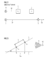
Figur 1- ein hinter dem Ohr tragbares Hörhilfegerät in stark vereinfachter, schematischer Darstellung nach dem Stand der Technik,
- Figur 2
- die elektrische Verschaltung zweier Mikrofone zu einem Richtmikrofonsystem gemäß dem Stand der Technik,
- Figur 3
- die Position zweier Mikrofone in Bezug auf eine Schallquelle, und
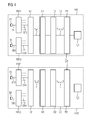
- Figur 4
- ein Hörhilfegerätesystem mit zwei Hörhilfegeräten, bei denen eine optimierte Signalverzögerung zwischen jeweils zwei zu einem Richtmikrofonsystem verschalteten Mikrofonen ermittelbar ist.
- FIG. 1
- a behind the ear portable hearing aid in a highly simplified, schematic representation of the prior art,
- FIG. 2
- the electrical connection of two microphones to a directional microphone system according to the prior art,
- FIG. 3
- the position of two microphones with respect to a sound source, and
- FIG. 4
- a hearing aid device system with two hearing aids, in which an optimized signal delay between each two connected to a directional microphone microphones can be determined.
Als Besonderheit umfasst die Signalverarbeitungseinheit des bekannten Hörhilfegerätes gemäß
Aus
Wird die interne Zeitverzögerung Ti so eingestellt, dass sie der Laufzeit eines akustischen Signals zwischen den beiden Mikrofonen F und B entspricht (Basis-Zeitverzögerung), so wird das akustische Signal einer auf der Verbindungslinie der beiden Mikrofone liegenden Signalquelle am Wenigsten gedämpft, wenn sich die Signalquelle vor dem vorderen Mikrofon F befindet, und maximal gedämpft, wenn sich die Signalquelle hinter dem hinteren Mikrofon B befindet. Durch Variation der internen Zeitverzögerung Ti kann die Richtung der maximalen Dämpfung in bekannter Weise im Raum geschwenkt werden. Dadurch können Richtcharakteristiken wie "Kardioid-Charakteristik", "Super-Kardioid-Charakteristik", "Hyper-Kardioid-Charakteristik", "Acht-Charakteristik" etc eingestellt werden.If the internal time delay T i is set to correspond to the propagation time of an acoustic signal between the two microphones F and B (base time delay), the acoustic signal of a signal source on the line connecting the two microphones will be least attenuated when the signal source is located in front of the front microphone F, and maximally attenuated when the signal source is behind the rear microphone B. By varying the internal time delay T i , the direction of the maximum attenuation can be pivoted in space in a known manner. As a result, directional characteristics such as "cardioid characteristic", "super cardioid characteristic", "hyper cardioid characteristic", "eight characteristic" etc can be set.
Die Erfindung ist nicht auf die gezeigte übliche Ausführungsform eines Richtmikrofonsystems für ein Hörhilfegerät beschränkt. Vielmehr ist diese analog auch auf andere Verschaltungen der Mikrofone und Richtmikrofonsysteme mit mehr als zwei Mikrofonen übertragbar.The invention is not limited to the shown conventional embodiment of a directional microphone system for a hearing aid. Rather, this analog is also applicable to other interconnections of microphones and directional microphone systems with more than two microphones.
Liegt nun - wie in
Gemäß der Erfindung wird automatisch eine aus der effektiven Distanz deff resultierende Zeitverzögerung ermittelt und eingestellt.According to the invention, a time delay resulting from the effective distance d eff is automatically determined and set.
Bei manchen Hörhilfegeräten wird bereits bei der Grundeinstellung davon ausgegangen, dass die Mikrofone des Richtmikrofonsystems nicht in einer horizontalen Ebene liegen, sondern dass auch bei der idealen Trageposition eine Gerade durch die Mikrofone einen vorgegebenen Winkel α mit der Horizontalen einschließt. Dies ändert jedoch nichts an der erfindungsgemäßen Vorgehensweise, da auch hierbei die ideale Trageposition von der tatsächlichen individuellen Trageposition abweichen kann und eine derartige Abweichung erfindungsgemäß erfasst wird und ihre Auswirkungen entsprechend korrigiert werden.In some hearing aids, it is already assumed in the basic setting that the microphones of the directional microphone system are not in a horizontal plane, but that even with the ideal carrying position a straight line through the microphones includes a predetermined angle α with the horizontal. However, this does not change the procedure according to the invention, since in this case too the ideal carrying position can deviate from the actual individual carrying position and such a deviation is detected according to the invention and its effects are corrected accordingly.
Die Mikrofonsignale SF3, SF4 des betreffenden Frequenzbandes sind bei dem Hörhilfegerät HA1 zunächst einer Kreuzkorrelationsanalyseeinheit K1 zugeführt. Die von einer Zeitverzögerung τ abhängige Kreuzkorrelationsfunktion der Mikrofonsignale hat bei einer Zeitverzögerung τ leff1 ein Maximum, die der Laufzeit des akustischen Signals zwischen den beiden Mikrofonen entspricht. Vorteilhaft werden bei der Erfindung innerhalb eines bestimmten Zeitraumes, beispielsweise innerhalb einer Minute, mehrere Kreuzkorrelationsfunktionen der Mikrofonsignale SF3 und SF4 in Abhängigkeit von der Zeitverzögerung τ bestimmt. Die statistische Auswertung der ermittelten Kreuzkorrelationsfunktionen erfolgt anschließend in einer Histogramm-Analyseeinheit H1, die Teil einer Steuereinheit C1 ist. Dabei wird für den betrachteten Zeitraum die relative Häufigkeit der ermittelten effektiven Zeitverzögerungen τ eff1 in Abhängigkeit von der Zeitverzögerung τ aufgetragen, bei denen die jeweilige Kreuzkorrelationsfunktion ihr Maximum hatte. In einer Zeitverzögerungsbestimmungseinheit D1 wird daraus dann eine resultierende effektive Zeitverzögerung τ eff, res1 bestimmt, bei der die Kreuzkorrelationsfunktionen am häufigsten ihr Maximum aufwiesen. Diese Zeitverzögerung wird dann als mögliche interne Zeitverzögerung herangezogen. Bevor jedoch die interne Zeitverzögerung tatsächlich eingestellt wird, erfolgt vorzugsweise zunächst noch eine Plausibilitätsprüfung der resultierenden effektiven Zeitverzögerung τ eff, res 1 in einer Plausibilitätsprüfungseinheit P1. Vorzugsweise werden in der Plausibilitätsprüfungseinheit P1 ein Vergleich der ermittelten, resultierenden effektiven Zeitverzögerung τ eff, res1 mit einem vorgegebenen Sollwert-Bereich sowie ein Vergleich mit der in dem zweiten Hörhilfegerät HA2 in analoger Weise ermittelten, resultierenden effektiven Zeitverzögerung τeff, res2 durchgeführt. Starke Abweichungen der in beiden Hörhilfsgeräten HA1 und HA2 ermittelten, resultierenden effektiven Zeitverzögerungen τ eff, res1 und τ eff, res2 deuten auf unbrauchbare Ergebnisse hin.The microphone signals SF3, SF4 of the relevant frequency band are first supplied to the hearing aid HA1 to a cross-correlation analysis unit K1. The time dependent on a time delay τ cross correlation function of the microphone signals has a maximum at a
Bei einer erfolgreichen Plausibilitätsprüfung wird bei dem Hörhilfegerät HA1 die interne Verzögerung Ti1 und analog bei dem Hörhilfegerät HA2 die interne Verzögerung Ti2 in Abhängigkeit von der jeweils ermittelten, resultierenden effektiven Zeitverzögerung τ eff, res1 bzw. τ eff, res2 eingestellt. Insbesondere wird die interne Zeitverzögerung Ti1 bzw. Ti2 mit der erfindungsgemäß bestimmten, resultierenden effektiven Zeitverzögerung τ eff, res1 bzw. τ eff, res2 gleich gesetzt.In the case of a successful plausibility check, the
In analoger Weise erfolgt auch für das zweite Hörhilfegerät HA2 eines betreffenden Hörhilfegerätesystems die Ermittlung der internen Zeitverzögerung Ti2 mittels einer Steuereinheit C2, die eine Kreuzkorrelationsanalyseeinheit K2, eine Histogramm-Analyseeinheit H2, eine Zeitverzögerungsbestimmungseinheit D2 sowie eine Plausibilitätsprüfungseinheit P2 umfasst.In an analogous manner, the determination of the internal time delay T i 2 by means of a control unit C2, which comprises a cross correlation analysis unit K2, a histogram analysis unit H2, a time delay determination unit D2 and a plausibility check P2 also for the second hearing aid HA2 of a hearing aid device.
In den Hörhilfegeräten HA1 und HA2 erfolgt eine Verknüpfung der Mikrofonsignale, beispielsweise analog zu der Verknüpfung gemäß
Claims (18)
gekennzeichnet durch
wobei
marked by
in which
dadurch gekennzeichnet, dass
characterized in that
τ eff, res2) durchgeführt wird.A method for operating a hearing aid system with a first or on the left ear of a user portable Hearing aid (HA1) operated according to a method according to any one of claims 15 to 17, and having a second hearing aid device (HA2) which can be worn on or in the right ear of a user, operated in accordance with a method according to any one of claims 15 to 17, wherein the plausibility check is determined on the basis of a comparison of the effective time delays ( τ eff 1, τ eff 2) determined in the respective hearing aid device (HA1, HA2) or the resulting effective time delay ( τ eff , res 1,
τ eff , res 2) is performed.
Applications Claiming Priority (1)
| Application Number | Priority Date | Filing Date | Title |
|---|---|---|---|
| DE102011006471A DE102011006471B4 (en) | 2011-03-31 | 2011-03-31 | Hearing aid device and hearing aid system with a directional microphone system and method for adjusting a directional microphone in a hearing aid |
Publications (3)
| Publication Number | Publication Date |
|---|---|
| EP2506603A2 true EP2506603A2 (en) | 2012-10-03 |
| EP2506603A3 EP2506603A3 (en) | 2016-04-20 |
| EP2506603B1 EP2506603B1 (en) | 2019-07-24 |
Family
ID=45841384
Family Applications (1)
| Application Number | Title | Priority Date | Filing Date |
|---|---|---|---|
| EP12160523.2A Active EP2506603B1 (en) | 2011-03-31 | 2012-03-21 | Hearing aid system with a directional microphone system and method for operating such a hearing aid system with said directional microphone system |
Country Status (4)
| Country | Link |
|---|---|
| US (1) | US9060232B2 (en) |
| EP (1) | EP2506603B1 (en) |
| DE (1) | DE102011006471B4 (en) |
| DK (1) | DK2506603T3 (en) |
Cited By (2)
| Publication number | Priority date | Publication date | Assignee | Title |
|---|---|---|---|---|
| EP2928214A1 (en) * | 2014-04-03 | 2015-10-07 | Oticon A/s | A binaural hearing assistance system comprising binaural noise reduction |
| EP2717597B1 (en) | 2012-10-08 | 2020-06-24 | Oticon A/s | Hearing device with brain-wave dependent audio processing |
Families Citing this family (10)
| Publication number | Priority date | Publication date | Assignee | Title |
|---|---|---|---|---|
| US8918197B2 (en) | 2012-06-13 | 2014-12-23 | Avraham Suhami | Audio communication networks |
| EP2928211A1 (en) * | 2014-04-04 | 2015-10-07 | Oticon A/s | Self-calibration of multi-microphone noise reduction system for hearing assistance devices using an auxiliary device |
| EP3269152B1 (en) * | 2015-03-13 | 2020-01-08 | Sonova AG | Method for determining useful hearing device features based on logged sound classification data |
| US10397710B2 (en) | 2015-12-18 | 2019-08-27 | Cochlear Limited | Neutralizing the effect of a medical device location |
| US10341791B2 (en) | 2016-02-08 | 2019-07-02 | K/S Himpp | Hearing augmentation systems and methods |
| US10284998B2 (en) | 2016-02-08 | 2019-05-07 | K/S Himpp | Hearing augmentation systems and methods |
| US10750293B2 (en) | 2016-02-08 | 2020-08-18 | Hearing Instrument Manufacture Patent Partnership | Hearing augmentation systems and methods |
| US10390155B2 (en) | 2016-02-08 | 2019-08-20 | K/S Himpp | Hearing augmentation systems and methods |
| DE102016216054A1 (en) * | 2016-08-25 | 2018-03-01 | Sivantos Pte. Ltd. | Method and device for setting a hearing aid device |
| US11937047B1 (en) * | 2023-08-04 | 2024-03-19 | Chromatic Inc. | Ear-worn device with neural network for noise reduction and/or spatial focusing using multiple input audio signals |
Citations (4)
| Publication number | Priority date | Publication date | Assignee | Title |
|---|---|---|---|---|
| EP0064042A1 (en) | 1981-04-16 | 1982-11-03 | Stephan Mangold | Programmable signal processing device |
| US5757933A (en) | 1996-12-11 | 1998-05-26 | Micro Ear Technology, Inc. | In-the-ear hearing aid with directional microphone system |
| US20020041696A1 (en) | 2000-10-04 | 2002-04-11 | Topholm & Westermann Aps | Hearing aid with adaptive matching of input transducers |
| US7340068B2 (en) | 2003-02-19 | 2008-03-04 | Oticon A/S | Device and method for detecting wind noise |
Family Cites Families (1)
| Publication number | Priority date | Publication date | Assignee | Title |
|---|---|---|---|---|
| DE102004010867B3 (en) * | 2004-03-05 | 2005-08-18 | Siemens Audiologische Technik Gmbh | Matching phases of microphones of hearing aid directional microphone involves matching second signal level to first by varying transition time of output signal from microphone without taking into account sound source position information |
-
2011
- 2011-03-31 DE DE102011006471A patent/DE102011006471B4/en not_active Expired - Fee Related
-
2012
- 2012-03-21 EP EP12160523.2A patent/EP2506603B1/en active Active
- 2012-03-21 DK DK12160523T patent/DK2506603T3/en active
- 2012-04-02 US US13/437,046 patent/US9060232B2/en active Active
Patent Citations (4)
| Publication number | Priority date | Publication date | Assignee | Title |
|---|---|---|---|---|
| EP0064042A1 (en) | 1981-04-16 | 1982-11-03 | Stephan Mangold | Programmable signal processing device |
| US5757933A (en) | 1996-12-11 | 1998-05-26 | Micro Ear Technology, Inc. | In-the-ear hearing aid with directional microphone system |
| US20020041696A1 (en) | 2000-10-04 | 2002-04-11 | Topholm & Westermann Aps | Hearing aid with adaptive matching of input transducers |
| US7340068B2 (en) | 2003-02-19 | 2008-03-04 | Oticon A/S | Device and method for detecting wind noise |
Cited By (7)
| Publication number | Priority date | Publication date | Assignee | Title |
|---|---|---|---|---|
| EP2717597B1 (en) | 2012-10-08 | 2020-06-24 | Oticon A/s | Hearing device with brain-wave dependent audio processing |
| EP2717597B2 (en) † | 2012-10-08 | 2023-08-09 | Oticon A/s | Hearing device with brain-wave dependent audio processing |
| EP2928214A1 (en) * | 2014-04-03 | 2015-10-07 | Oticon A/s | A binaural hearing assistance system comprising binaural noise reduction |
| EP2928210A1 (en) * | 2014-04-03 | 2015-10-07 | Oticon A/s | A binaural hearing assistance system comprising binaural noise reduction |
| US9516430B2 (en) | 2014-04-03 | 2016-12-06 | Oticon A/S | Binaural hearing assistance system comprising binaural noise reduction |
| US10123134B2 (en) | 2014-04-03 | 2018-11-06 | Oticon A/S | Binaural hearing assistance system comprising binaural noise reduction |
| EP2928214B1 (en) | 2014-04-03 | 2019-05-08 | Oticon A/s | A binaural hearing assistance system comprising binaural noise reduction |
Also Published As
| Publication number | Publication date |
|---|---|
| DE102011006471B4 (en) | 2013-08-08 |
| DK2506603T3 (en) | 2019-10-28 |
| US20120250916A1 (en) | 2012-10-04 |
| EP2506603A3 (en) | 2016-04-20 |
| US9060232B2 (en) | 2015-06-16 |
| DE102011006471A1 (en) | 2012-10-04 |
| EP2506603B1 (en) | 2019-07-24 |
Similar Documents
| Publication | Publication Date | Title |
|---|---|---|
| EP2506603B1 (en) | Hearing aid system with a directional microphone system and method for operating such a hearing aid system with said directional microphone system | |
| EP2180726B2 (en) | Sound localization in binaural hearing aids | |
| EP3451705B1 (en) | Method and apparatus for the rapid detection of own voice | |
| EP1771038B1 (en) | Method for operating a hearing-aid system for binaural treatment of a user | |
| EP2164283B1 (en) | Hearing aid and operation of a hearing aid with frequency transposition | |
| DE102007017761B4 (en) | Method for adapting a binaural hearing aid system | |
| EP2840809B1 (en) | Control of the strength of the effect of a binaural directional microphone | |
| DE102013215131A1 (en) | Method for tracking a sound source | |
| EP2811762B1 (en) | Logic-based binaural beam forming system | |
| EP1465453B1 (en) | Automatic adjustment of a directional microphone system with at least three microphones | |
| EP3461147A1 (en) | Method for operating a hearing device | |
| EP2226795A1 (en) | Hearing aid and method for reducing interference in a hearing aid | |
| EP2595414A1 (en) | Hearing aid with a device for reducing a microphone noise and method for reducing a microphone noise | |
| EP2822300B1 (en) | Detection of listening situations with different signal sources | |
| EP2161949A2 (en) | Method for operating a hearing aid with directional effect and accompanying hearing aid | |
| EP2658289B1 (en) | Method for controlling an alignment characteristic and hearing aid | |
| EP2373063A1 (en) | Hearing device and method for setting the same for acoustic feedback-free operation | |
| EP2793488B1 (en) | Binaural microphone adjustment by means of the user's own voice | |
| DE102009014053B4 (en) | Method for setting a directional characteristic and hearing devices | |
| DE102021210098A1 (en) | Method of operating a hearing aid | |
| DE102022207373A1 (en) | Method for operating a binaural hearing aid | |
| WO2011107545A2 (en) | Method for adjusting a directional hearing device |
Legal Events
| Date | Code | Title | Description |
|---|---|---|---|
| PUAI | Public reference made under article 153(3) epc to a published international application that has entered the european phase |
Free format text: ORIGINAL CODE: 0009012 |
|
| AK | Designated contracting states |
Kind code of ref document: A2 Designated state(s): AL AT BE BG CH CY CZ DE DK EE ES FI FR GB GR HR HU IE IS IT LI LT LU LV MC MK MT NL NO PL PT RO RS SE SI SK SM TR |
|
| AX | Request for extension of the european patent |
Extension state: BA ME |
|
| RAP1 | Party data changed (applicant data changed or rights of an application transferred) |
Owner name: SIVANTOS PTE. LTD. |
|
| PUAL | Search report despatched |
Free format text: ORIGINAL CODE: 0009013 |
|
| AK | Designated contracting states |
Kind code of ref document: A3 Designated state(s): AL AT BE BG CH CY CZ DE DK EE ES FI FR GB GR HR HU IE IS IT LI LT LU LV MC MK MT NL NO PL PT RO RS SE SI SK SM TR |
|
| AX | Request for extension of the european patent |
Extension state: BA ME |
|
| RIC1 | Information provided on ipc code assigned before grant |
Ipc: H04R 25/00 20060101AFI20160317BHEP Ipc: H04R 29/00 20060101ALI20160317BHEP |
|
| 17P | Request for examination filed |
Effective date: 20161017 |
|
| RBV | Designated contracting states (corrected) |
Designated state(s): AL AT BE BG CH CY CZ DE DK EE ES FI FR GB GR HR HU IE IS IT LI LT LU LV MC MK MT NL NO PL PT RO RS SE SI SK SM TR |
|
| RIN1 | Information on inventor provided before grant (corrected) |
Inventor name: JUNIUS, DIRK Inventor name: BEST, SEBASTIAN Inventor name: MUELLER-WEHLAU, MATTHIAS Inventor name: HAIN, JENS |
|
| RAP1 | Party data changed (applicant data changed or rights of an application transferred) |
Owner name: SIVANTOS PTE. LTD. |
|
| GRAP | Despatch of communication of intention to grant a patent |
Free format text: ORIGINAL CODE: EPIDOSNIGR1 |
|
| STAA | Information on the status of an ep patent application or granted ep patent |
Free format text: STATUS: GRANT OF PATENT IS INTENDED |
|
| INTG | Intention to grant announced |
Effective date: 20180418 |
|
| GRAJ | Information related to disapproval of communication of intention to grant by the applicant or resumption of examination proceedings by the epo deleted |
Free format text: ORIGINAL CODE: EPIDOSDIGR1 |
|
| STAA | Information on the status of an ep patent application or granted ep patent |
Free format text: STATUS: REQUEST FOR EXAMINATION WAS MADE |
|
| GRAP | Despatch of communication of intention to grant a patent |
Free format text: ORIGINAL CODE: EPIDOSNIGR1 |
|
| STAA | Information on the status of an ep patent application or granted ep patent |
Free format text: STATUS: GRANT OF PATENT IS INTENDED |
|
| INTC | Intention to grant announced (deleted) | ||
| INTG | Intention to grant announced |
Effective date: 20180906 |
|
| GRAJ | Information related to disapproval of communication of intention to grant by the applicant or resumption of examination proceedings by the epo deleted |
Free format text: ORIGINAL CODE: EPIDOSDIGR1 |
|
| GRAP | Despatch of communication of intention to grant a patent |
Free format text: ORIGINAL CODE: EPIDOSNIGR1 |
|
| INTG | Intention to grant announced |
Effective date: 20190218 |
|
| GRAS | Grant fee paid |
Free format text: ORIGINAL CODE: EPIDOSNIGR3 |
|
| GRAA | (expected) grant |
Free format text: ORIGINAL CODE: 0009210 |
|
| STAA | Information on the status of an ep patent application or granted ep patent |
Free format text: STATUS: THE PATENT HAS BEEN GRANTED |
|
| AK | Designated contracting states |
Kind code of ref document: B1 Designated state(s): AL AT BE BG CH CY CZ DE DK EE ES FI FR GB GR HR HU IE IS IT LI LT LU LV MC MK MT NL NO PL PT RO RS SE SI SK SM TR |
|
| REG | Reference to a national code |
Ref country code: GB Ref legal event code: FG4D Free format text: NOT ENGLISH |
|
| REG | Reference to a national code |
Ref country code: CH Ref legal event code: EP |
|
| REG | Reference to a national code |
Ref country code: DE Ref legal event code: R096 Ref document number: 502012015048 Country of ref document: DE |
|
| REG | Reference to a national code |
Ref country code: AT Ref legal event code: REF Ref document number: 1159720 Country of ref document: AT Kind code of ref document: T Effective date: 20190815 |
|
| REG | Reference to a national code |
Ref country code: IE Ref legal event code: FG4D Free format text: LANGUAGE OF EP DOCUMENT: GERMAN |
|
| REG | Reference to a national code |
Ref country code: CH Ref legal event code: NV Representative=s name: E. BLUM AND CO. AG PATENT- UND MARKENANWAELTE , CH |
|
| REG | Reference to a national code |
Ref country code: DK Ref legal event code: T3 Effective date: 20191024 |
|
| REG | Reference to a national code |
Ref country code: NL Ref legal event code: MP Effective date: 20190724 |
|
| REG | Reference to a national code |
Ref country code: LT Ref legal event code: MG4D |
|
| PG25 | Lapsed in a contracting state [announced via postgrant information from national office to epo] |
Ref country code: SE Free format text: LAPSE BECAUSE OF FAILURE TO SUBMIT A TRANSLATION OF THE DESCRIPTION OR TO PAY THE FEE WITHIN THE PRESCRIBED TIME-LIMIT Effective date: 20190724 Ref country code: HR Free format text: LAPSE BECAUSE OF FAILURE TO SUBMIT A TRANSLATION OF THE DESCRIPTION OR TO PAY THE FEE WITHIN THE PRESCRIBED TIME-LIMIT Effective date: 20190724 Ref country code: PT Free format text: LAPSE BECAUSE OF FAILURE TO SUBMIT A TRANSLATION OF THE DESCRIPTION OR TO PAY THE FEE WITHIN THE PRESCRIBED TIME-LIMIT Effective date: 20191125 Ref country code: BG Free format text: LAPSE BECAUSE OF FAILURE TO SUBMIT A TRANSLATION OF THE DESCRIPTION OR TO PAY THE FEE WITHIN THE PRESCRIBED TIME-LIMIT Effective date: 20191024 Ref country code: NL Free format text: LAPSE BECAUSE OF FAILURE TO SUBMIT A TRANSLATION OF THE DESCRIPTION OR TO PAY THE FEE WITHIN THE PRESCRIBED TIME-LIMIT Effective date: 20190724 Ref country code: LT Free format text: LAPSE BECAUSE OF FAILURE TO SUBMIT A TRANSLATION OF THE DESCRIPTION OR TO PAY THE FEE WITHIN THE PRESCRIBED TIME-LIMIT Effective date: 20190724 Ref country code: FI Free format text: LAPSE BECAUSE OF FAILURE TO SUBMIT A TRANSLATION OF THE DESCRIPTION OR TO PAY THE FEE WITHIN THE PRESCRIBED TIME-LIMIT Effective date: 20190724 Ref country code: NO Free format text: LAPSE BECAUSE OF FAILURE TO SUBMIT A TRANSLATION OF THE DESCRIPTION OR TO PAY THE FEE WITHIN THE PRESCRIBED TIME-LIMIT Effective date: 20191024 |
|
| PG25 | Lapsed in a contracting state [announced via postgrant information from national office to epo] |
Ref country code: ES Free format text: LAPSE BECAUSE OF FAILURE TO SUBMIT A TRANSLATION OF THE DESCRIPTION OR TO PAY THE FEE WITHIN THE PRESCRIBED TIME-LIMIT Effective date: 20190724 Ref country code: RS Free format text: LAPSE BECAUSE OF FAILURE TO SUBMIT A TRANSLATION OF THE DESCRIPTION OR TO PAY THE FEE WITHIN THE PRESCRIBED TIME-LIMIT Effective date: 20190724 Ref country code: IS Free format text: LAPSE BECAUSE OF FAILURE TO SUBMIT A TRANSLATION OF THE DESCRIPTION OR TO PAY THE FEE WITHIN THE PRESCRIBED TIME-LIMIT Effective date: 20191124 Ref country code: LV Free format text: LAPSE BECAUSE OF FAILURE TO SUBMIT A TRANSLATION OF THE DESCRIPTION OR TO PAY THE FEE WITHIN THE PRESCRIBED TIME-LIMIT Effective date: 20190724 Ref country code: AL Free format text: LAPSE BECAUSE OF FAILURE TO SUBMIT A TRANSLATION OF THE DESCRIPTION OR TO PAY THE FEE WITHIN THE PRESCRIBED TIME-LIMIT Effective date: 20190724 Ref country code: GR Free format text: LAPSE BECAUSE OF FAILURE TO SUBMIT A TRANSLATION OF THE DESCRIPTION OR TO PAY THE FEE WITHIN THE PRESCRIBED TIME-LIMIT Effective date: 20191025 |
|
| PG25 | Lapsed in a contracting state [announced via postgrant information from national office to epo] |
Ref country code: TR Free format text: LAPSE BECAUSE OF FAILURE TO SUBMIT A TRANSLATION OF THE DESCRIPTION OR TO PAY THE FEE WITHIN THE PRESCRIBED TIME-LIMIT Effective date: 20190724 |
|
| PG25 | Lapsed in a contracting state [announced via postgrant information from national office to epo] |
Ref country code: RO Free format text: LAPSE BECAUSE OF FAILURE TO SUBMIT A TRANSLATION OF THE DESCRIPTION OR TO PAY THE FEE WITHIN THE PRESCRIBED TIME-LIMIT Effective date: 20190724 Ref country code: IT Free format text: LAPSE BECAUSE OF FAILURE TO SUBMIT A TRANSLATION OF THE DESCRIPTION OR TO PAY THE FEE WITHIN THE PRESCRIBED TIME-LIMIT Effective date: 20190724 Ref country code: EE Free format text: LAPSE BECAUSE OF FAILURE TO SUBMIT A TRANSLATION OF THE DESCRIPTION OR TO PAY THE FEE WITHIN THE PRESCRIBED TIME-LIMIT Effective date: 20190724 Ref country code: PL Free format text: LAPSE BECAUSE OF FAILURE TO SUBMIT A TRANSLATION OF THE DESCRIPTION OR TO PAY THE FEE WITHIN THE PRESCRIBED TIME-LIMIT Effective date: 20190724 |
|
| PG25 | Lapsed in a contracting state [announced via postgrant information from national office to epo] |
Ref country code: CZ Free format text: LAPSE BECAUSE OF FAILURE TO SUBMIT A TRANSLATION OF THE DESCRIPTION OR TO PAY THE FEE WITHIN THE PRESCRIBED TIME-LIMIT Effective date: 20190724 Ref country code: SK Free format text: LAPSE BECAUSE OF FAILURE TO SUBMIT A TRANSLATION OF THE DESCRIPTION OR TO PAY THE FEE WITHIN THE PRESCRIBED TIME-LIMIT Effective date: 20190724 Ref country code: IS Free format text: LAPSE BECAUSE OF FAILURE TO SUBMIT A TRANSLATION OF THE DESCRIPTION OR TO PAY THE FEE WITHIN THE PRESCRIBED TIME-LIMIT Effective date: 20200224 Ref country code: SM Free format text: LAPSE BECAUSE OF FAILURE TO SUBMIT A TRANSLATION OF THE DESCRIPTION OR TO PAY THE FEE WITHIN THE PRESCRIBED TIME-LIMIT Effective date: 20190724 |
|
| REG | Reference to a national code |
Ref country code: DE Ref legal event code: R097 Ref document number: 502012015048 Country of ref document: DE |
|
| PLBE | No opposition filed within time limit |
Free format text: ORIGINAL CODE: 0009261 |
|
| STAA | Information on the status of an ep patent application or granted ep patent |
Free format text: STATUS: NO OPPOSITION FILED WITHIN TIME LIMIT |
|
| PG2D | Information on lapse in contracting state deleted |
Ref country code: IS |
|
| 26N | No opposition filed |
Effective date: 20200603 |
|
| PG25 | Lapsed in a contracting state [announced via postgrant information from national office to epo] |
Ref country code: SI Free format text: LAPSE BECAUSE OF FAILURE TO SUBMIT A TRANSLATION OF THE DESCRIPTION OR TO PAY THE FEE WITHIN THE PRESCRIBED TIME-LIMIT Effective date: 20190724 |
|
| PG25 | Lapsed in a contracting state [announced via postgrant information from national office to epo] |
Ref country code: MC Free format text: LAPSE BECAUSE OF FAILURE TO SUBMIT A TRANSLATION OF THE DESCRIPTION OR TO PAY THE FEE WITHIN THE PRESCRIBED TIME-LIMIT Effective date: 20190724 |
|
| REG | Reference to a national code |
Ref country code: BE Ref legal event code: MM Effective date: 20200331 |
|
| PG25 | Lapsed in a contracting state [announced via postgrant information from national office to epo] |
Ref country code: LU Free format text: LAPSE BECAUSE OF NON-PAYMENT OF DUE FEES Effective date: 20200321 |
|
| PG25 | Lapsed in a contracting state [announced via postgrant information from national office to epo] |
Ref country code: IE Free format text: LAPSE BECAUSE OF NON-PAYMENT OF DUE FEES Effective date: 20200321 |
|
| PG25 | Lapsed in a contracting state [announced via postgrant information from national office to epo] |
Ref country code: BE Free format text: LAPSE BECAUSE OF NON-PAYMENT OF DUE FEES Effective date: 20200331 |
|
| REG | Reference to a national code |
Ref country code: AT Ref legal event code: MM01 Ref document number: 1159720 Country of ref document: AT Kind code of ref document: T Effective date: 20200321 |
|
| PG25 | Lapsed in a contracting state [announced via postgrant information from national office to epo] |
Ref country code: AT Free format text: LAPSE BECAUSE OF NON-PAYMENT OF DUE FEES Effective date: 20200321 |
|
| PG25 | Lapsed in a contracting state [announced via postgrant information from national office to epo] |
Ref country code: MT Free format text: LAPSE BECAUSE OF FAILURE TO SUBMIT A TRANSLATION OF THE DESCRIPTION OR TO PAY THE FEE WITHIN THE PRESCRIBED TIME-LIMIT Effective date: 20190724 Ref country code: CY Free format text: LAPSE BECAUSE OF FAILURE TO SUBMIT A TRANSLATION OF THE DESCRIPTION OR TO PAY THE FEE WITHIN THE PRESCRIBED TIME-LIMIT Effective date: 20190724 |
|
| PG25 | Lapsed in a contracting state [announced via postgrant information from national office to epo] |
Ref country code: MK Free format text: LAPSE BECAUSE OF FAILURE TO SUBMIT A TRANSLATION OF THE DESCRIPTION OR TO PAY THE FEE WITHIN THE PRESCRIBED TIME-LIMIT Effective date: 20190724 |
|
| PGFP | Annual fee paid to national office [announced via postgrant information from national office to epo] |
Ref country code: FR Payment date: 20230320 Year of fee payment: 12 Ref country code: DK Payment date: 20230323 Year of fee payment: 12 |
|
| PGFP | Annual fee paid to national office [announced via postgrant information from national office to epo] |
Ref country code: GB Payment date: 20230323 Year of fee payment: 12 Ref country code: DE Payment date: 20230320 Year of fee payment: 12 |
|
| PGFP | Annual fee paid to national office [announced via postgrant information from national office to epo] |
Ref country code: CH Payment date: 20230402 Year of fee payment: 12 |