EP2506570B1 - Method and system for playing video information, and video information content - Google Patents
Method and system for playing video information, and video information content Download PDFInfo
- Publication number
- EP2506570B1 EP2506570B1 EP10832765.1A EP10832765A EP2506570B1 EP 2506570 B1 EP2506570 B1 EP 2506570B1 EP 10832765 A EP10832765 A EP 10832765A EP 2506570 B1 EP2506570 B1 EP 2506570B1
- Authority
- EP
- European Patent Office
- Prior art keywords
- video information
- reproduction
- information reproducing
- content
- reproduction time
- Prior art date
- Legal status (The legal status is an assumption and is not a legal conclusion. Google has not performed a legal analysis and makes no representation as to the accuracy of the status listed.)
- Not-in-force
Links
Images


Classifications
-
- H—ELECTRICITY
- H04—ELECTRIC COMMUNICATION TECHNIQUE
- H04N—PICTORIAL COMMUNICATION, e.g. TELEVISION
- H04N9/00—Details of colour television systems
- H04N9/79—Processing of colour television signals in connection with recording
- H04N9/80—Transformation of the television signal for recording, e.g. modulation, frequency changing; Inverse transformation for playback
- H04N9/804—Transformation of the television signal for recording, e.g. modulation, frequency changing; Inverse transformation for playback involving pulse code modulation of the colour picture signal components
- H04N9/8042—Transformation of the television signal for recording, e.g. modulation, frequency changing; Inverse transformation for playback involving pulse code modulation of the colour picture signal components involving data reduction
-
- G—PHYSICS
- G11—INFORMATION STORAGE
- G11B—INFORMATION STORAGE BASED ON RELATIVE MOVEMENT BETWEEN RECORD CARRIER AND TRANSDUCER
- G11B20/00—Signal processing not specific to the method of recording or reproducing; Circuits therefor
- G11B20/10—Digital recording or reproducing
-
- G—PHYSICS
- G11—INFORMATION STORAGE
- G11B—INFORMATION STORAGE BASED ON RELATIVE MOVEMENT BETWEEN RECORD CARRIER AND TRANSDUCER
- G11B20/00—Signal processing not specific to the method of recording or reproducing; Circuits therefor
- G11B20/10—Digital recording or reproducing
- G11B20/10527—Audio or video recording; Data buffering arrangements
-
- H—ELECTRICITY
- H04—ELECTRIC COMMUNICATION TECHNIQUE
- H04N—PICTORIAL COMMUNICATION, e.g. TELEVISION
- H04N21/00—Selective content distribution, e.g. interactive television or video on demand [VOD]
- H04N21/20—Servers specifically adapted for the distribution of content, e.g. VOD servers; Operations thereof
- H04N21/23—Processing of content or additional data; Elementary server operations; Server middleware
- H04N21/242—Synchronization processes, e.g. processing of PCR [Program Clock References]
-
- H—ELECTRICITY
- H04—ELECTRIC COMMUNICATION TECHNIQUE
- H04N—PICTORIAL COMMUNICATION, e.g. TELEVISION
- H04N21/00—Selective content distribution, e.g. interactive television or video on demand [VOD]
- H04N21/40—Client devices specifically adapted for the reception of or interaction with content, e.g. set-top-box [STB]; Operations thereof
- H04N21/43—Processing of content or additional data, e.g. demultiplexing additional data from a digital video stream; Elementary client operations, e.g. monitoring of home network or synchronising decoder's clock; Client middleware
- H04N21/432—Content retrieval operation from a local storage medium, e.g. hard-disk
- H04N21/4325—Content retrieval operation from a local storage medium, e.g. hard-disk by playing back content from the storage medium
-
- H—ELECTRICITY
- H04—ELECTRIC COMMUNICATION TECHNIQUE
- H04N—PICTORIAL COMMUNICATION, e.g. TELEVISION
- H04N21/00—Selective content distribution, e.g. interactive television or video on demand [VOD]
- H04N21/40—Client devices specifically adapted for the reception of or interaction with content, e.g. set-top-box [STB]; Operations thereof
- H04N21/43—Processing of content or additional data, e.g. demultiplexing additional data from a digital video stream; Elementary client operations, e.g. monitoring of home network or synchronising decoder's clock; Client middleware
- H04N21/44—Processing of video elementary streams, e.g. splicing a video clip retrieved from local storage with an incoming video stream, rendering scenes according to MPEG-4 scene graphs
- H04N21/44016—Processing of video elementary streams, e.g. splicing a video clip retrieved from local storage with an incoming video stream, rendering scenes according to MPEG-4 scene graphs involving splicing one content stream with another content stream, e.g. for substituting a video clip
-
- H—ELECTRICITY
- H04—ELECTRIC COMMUNICATION TECHNIQUE
- H04N—PICTORIAL COMMUNICATION, e.g. TELEVISION
- H04N21/00—Selective content distribution, e.g. interactive television or video on demand [VOD]
- H04N21/60—Network structure or processes for video distribution between server and client or between remote clients; Control signalling between clients, server and network components; Transmission of management data between server and client, e.g. sending from server to client commands for recording incoming content stream; Communication details between server and client
- H04N21/63—Control signaling related to video distribution between client, server and network components; Network processes for video distribution between server and clients or between remote clients, e.g. transmitting basic layer and enhancement layers over different transmission paths, setting up a peer-to-peer communication via Internet between remote STB's; Communication protocols; Addressing
- H04N21/633—Control signals issued by server directed to the network components or client
- H04N21/6332—Control signals issued by server directed to the network components or client directed to client
-
- H—ELECTRICITY
- H04—ELECTRIC COMMUNICATION TECHNIQUE
- H04N—PICTORIAL COMMUNICATION, e.g. TELEVISION
- H04N21/00—Selective content distribution, e.g. interactive television or video on demand [VOD]
- H04N21/80—Generation or processing of content or additional data by content creator independently of the distribution process; Content per se
- H04N21/85—Assembly of content; Generation of multimedia applications
- H04N21/854—Content authoring
- H04N21/8547—Content authoring involving timestamps for synchronizing content
-
- H—ELECTRICITY
- H04—ELECTRIC COMMUNICATION TECHNIQUE
- H04N—PICTORIAL COMMUNICATION, e.g. TELEVISION
- H04N5/00—Details of television systems
- H04N5/76—Television signal recording
- H04N5/91—Television signal processing therefor
- H04N5/92—Transformation of the television signal for recording, e.g. modulation, frequency changing; Inverse transformation for playback
-
- H—ELECTRICITY
- H04—ELECTRIC COMMUNICATION TECHNIQUE
- H04N—PICTORIAL COMMUNICATION, e.g. TELEVISION
- H04N5/00—Details of television systems
- H04N5/76—Television signal recording
- H04N5/91—Television signal processing therefor
- H04N5/93—Regeneration of the television signal or of selected parts thereof
-
- H—ELECTRICITY
- H04—ELECTRIC COMMUNICATION TECHNIQUE
- H04N—PICTORIAL COMMUNICATION, e.g. TELEVISION
- H04N9/00—Details of colour television systems
- H04N9/79—Processing of colour television signals in connection with recording
- H04N9/80—Transformation of the television signal for recording, e.g. modulation, frequency changing; Inverse transformation for playback
-
- G—PHYSICS
- G09—EDUCATION; CRYPTOGRAPHY; DISPLAY; ADVERTISING; SEALS
- G09G—ARRANGEMENTS OR CIRCUITS FOR CONTROL OF INDICATING DEVICES USING STATIC MEANS TO PRESENT VARIABLE INFORMATION
- G09G2340/00—Aspects of display data processing
- G09G2340/02—Handling of images in compressed format, e.g. JPEG, MPEG
-
- G—PHYSICS
- G09—EDUCATION; CRYPTOGRAPHY; DISPLAY; ADVERTISING; SEALS
- G09G—ARRANGEMENTS OR CIRCUITS FOR CONTROL OF INDICATING DEVICES USING STATIC MEANS TO PRESENT VARIABLE INFORMATION
- G09G2370/00—Aspects of data communication
- G09G2370/10—Use of a protocol of communication by packets in interfaces along the display data pipeline
-
- G—PHYSICS
- G11—INFORMATION STORAGE
- G11B—INFORMATION STORAGE BASED ON RELATIVE MOVEMENT BETWEEN RECORD CARRIER AND TRANSDUCER
- G11B20/00—Signal processing not specific to the method of recording or reproducing; Circuits therefor
- G11B20/10—Digital recording or reproducing
- G11B20/10527—Audio or video recording; Data buffering arrangements
- G11B2020/1062—Data buffering arrangements, e.g. recording or playback buffers
- G11B2020/1075—Data buffering arrangements, e.g. recording or playback buffers the usage of the buffer being restricted to a specific kind of data
- G11B2020/10759—Data buffering arrangements, e.g. recording or playback buffers the usage of the buffer being restricted to a specific kind of data content data
-
- G—PHYSICS
- G11—INFORMATION STORAGE
- G11B—INFORMATION STORAGE BASED ON RELATIVE MOVEMENT BETWEEN RECORD CARRIER AND TRANSDUCER
- G11B20/00—Signal processing not specific to the method of recording or reproducing; Circuits therefor
- G11B20/10—Digital recording or reproducing
- G11B20/10527—Audio or video recording; Data buffering arrangements
- G11B2020/1062—Data buffering arrangements, e.g. recording or playback buffers
- G11B2020/10805—Data buffering arrangements, e.g. recording or playback buffers involving specific measures to prevent a buffer overflow
-
- G—PHYSICS
- G11—INFORMATION STORAGE
- G11B—INFORMATION STORAGE BASED ON RELATIVE MOVEMENT BETWEEN RECORD CARRIER AND TRANSDUCER
- G11B20/00—Signal processing not specific to the method of recording or reproducing; Circuits therefor
- G11B20/10—Digital recording or reproducing
- G11B20/10527—Audio or video recording; Data buffering arrangements
- G11B2020/1062—Data buffering arrangements, e.g. recording or playback buffers
- G11B2020/10814—Data buffering arrangements, e.g. recording or playback buffers involving specific measures to prevent a buffer underrun
-
- H—ELECTRICITY
- H04—ELECTRIC COMMUNICATION TECHNIQUE
- H04N—PICTORIAL COMMUNICATION, e.g. TELEVISION
- H04N21/00—Selective content distribution, e.g. interactive television or video on demand [VOD]
- H04N21/20—Servers specifically adapted for the distribution of content, e.g. VOD servers; Operations thereof
- H04N21/23—Processing of content or additional data; Elementary server operations; Server middleware
- H04N21/24—Monitoring of processes or resources, e.g. monitoring of server load, available bandwidth, upstream requests
- H04N21/2401—Monitoring of the client buffer
-
- H—ELECTRICITY
- H04—ELECTRIC COMMUNICATION TECHNIQUE
- H04N—PICTORIAL COMMUNICATION, e.g. TELEVISION
- H04N21/00—Selective content distribution, e.g. interactive television or video on demand [VOD]
- H04N21/40—Client devices specifically adapted for the reception of or interaction with content, e.g. set-top-box [STB]; Operations thereof
- H04N21/43—Processing of content or additional data, e.g. demultiplexing additional data from a digital video stream; Elementary client operations, e.g. monitoring of home network or synchronising decoder's clock; Client middleware
- H04N21/4302—Content synchronisation processes, e.g. decoder synchronisation
-
- H—ELECTRICITY
- H04—ELECTRIC COMMUNICATION TECHNIQUE
- H04N—PICTORIAL COMMUNICATION, e.g. TELEVISION
- H04N21/00—Selective content distribution, e.g. interactive television or video on demand [VOD]
- H04N21/60—Network structure or processes for video distribution between server and client or between remote clients; Control signalling between clients, server and network components; Transmission of management data between server and client, e.g. sending from server to client commands for recording incoming content stream; Communication details between server and client
- H04N21/63—Control signaling related to video distribution between client, server and network components; Network processes for video distribution between server and clients or between remote clients, e.g. transmitting basic layer and enhancement layers over different transmission paths, setting up a peer-to-peer communication via Internet between remote STB's; Communication protocols; Addressing
- H04N21/64—Addressing
- H04N21/6405—Multicasting
-
- H—ELECTRICITY
- H04—ELECTRIC COMMUNICATION TECHNIQUE
- H04N—PICTORIAL COMMUNICATION, e.g. TELEVISION
- H04N9/00—Details of colour television systems
- H04N9/79—Processing of colour television signals in connection with recording
- H04N9/80—Transformation of the television signal for recording, e.g. modulation, frequency changing; Inverse transformation for playback
- H04N9/804—Transformation of the television signal for recording, e.g. modulation, frequency changing; Inverse transformation for playback involving pulse code modulation of the colour picture signal components
- H04N9/806—Transformation of the television signal for recording, e.g. modulation, frequency changing; Inverse transformation for playback involving pulse code modulation of the colour picture signal components with processing of the sound signal
- H04N9/8063—Transformation of the television signal for recording, e.g. modulation, frequency changing; Inverse transformation for playback involving pulse code modulation of the colour picture signal components with processing of the sound signal using time division multiplex of the PCM audio and PCM video signals
-
- H—ELECTRICITY
- H04—ELECTRIC COMMUNICATION TECHNIQUE
- H04N—PICTORIAL COMMUNICATION, e.g. TELEVISION
- H04N9/00—Details of colour television systems
- H04N9/79—Processing of colour television signals in connection with recording
- H04N9/80—Transformation of the television signal for recording, e.g. modulation, frequency changing; Inverse transformation for playback
- H04N9/82—Transformation of the television signal for recording, e.g. modulation, frequency changing; Inverse transformation for playback the individual colour picture signal components being recorded simultaneously only
- H04N9/8205—Transformation of the television signal for recording, e.g. modulation, frequency changing; Inverse transformation for playback the individual colour picture signal components being recorded simultaneously only involving the multiplexing of an additional signal and the colour video signal
Landscapes
- Engineering & Computer Science (AREA)
- Signal Processing (AREA)
- Multimedia (AREA)
- Databases & Information Systems (AREA)
- Computer Security & Cryptography (AREA)
- Two-Way Televisions, Distribution Of Moving Picture Or The Like (AREA)
- Television Signal Processing For Recording (AREA)
- Controls And Circuits For Display Device (AREA)
- Compression Or Coding Systems Of Tv Signals (AREA)
Description
- The present invention relates to a video information reproduction method and a video information reproduction system for reproducing encoded data delivered via a network or encoded data read from storage media. The present invention also relates to content delivered via networks or read from storage media.
- A program clock reference (PCR) included in a transport stream (TS) is generally used for synchronizing reproduction of content delivered to a plurality of reproducing devices without causing underflow or overflow of buffer memory (see, for example, Patent Document 1).
- Patent document 1: Japanese Patent Application Publication No.
2008-96756 - The publication of Fernando Boronat Segui et al., "An RTP/RTCP based approach for multimedia group and inter-stream synchronization" proposes the use of RTP/RTCP to provide synchronization. The feedback capabilities provided by RTCP and the ability to extend the protocol by extending and creating RTCP messages containing synchronization information is used. The proposal is implemented and tested in a University WAN. The experiments have shown that network load resulting from synchronization can be minimized and that asynchronies are within acceptable limits for multimedia applications.
- Document
US 6,061,399 relates to a timing synchronization method and apparatus for processing a compressed information stream comprising a plurality of information segments representative of a sequence of information frames. Information segments representative of information frames are deleted in response to an indicium of buffer overutilization. - In terrestrial digital broadcasts and other broadcasts using a TS (Transport Stream), data are transmitted from the data transmitter at a fixed bit rate, so that if the system clock of the decoder does not perfectly match the standard 27 MHz, the buffer memory may be emptied or overflow, making normal reproduction impossible. An available means of avoiding this problem is to use the PCR (Program Clock Reference) to correct the system clock of the decoder periodically. This enables the system clocks of all reproducing devices that receive a TS to be adjusted to the same time, so that when a plurality of reproducing devices are lined up to create a display, the display devices are all perfectly synchronized.
- DVD and Blu-ray players, and other devices for reproducing MPEG data, read the data from storage media in a way that prevents their decoder buffers from underflowing or overflowing, so that in general they do not require time correction of their system clocks, using PCR. For this reason, when data that have been read from storage media are sent to a plurality of reproducing devices and displayed on the plurality of reproducing devices, for example, system clock differences may cause the displays to lose synchronization after a few hours.
- The same thing may also happen in reproduction by network delivery. Data delivered via networks are not transmitted at a fixed bit rate as in broadcasting, so that the reproducing devices generally perform reproduction from large buffer memories, and as with DVD or the like, system clock correction by use of PCR is impossible. During prolonged reproduction, therefore, different display devices may lose synchronization.
- In signage applications, for example, multicast content must be reproduced in synchronization at all reproducing devices, but as described above, when data are read from storage media or delivered via a network, PCR cannot be used, so that during prolonged reproduction by a plurality of display devices, the problem of gradual loss of display synchronization occurs.
- The present invention addresses the above problem with the object of enabling a plurality of video information reproducing devices that reproduce data read from storage media or receive and reproduce data delivered via a network to synchronize their reproduction even under conditions in which system clock correction by use of PCR is not possible.
- The inventive video information reproduction method is a video information reproduction method for receiving content formed by a sequence including at least intra-frame encoded image information and inter-frame forward prediction encoded image information, and including time stamp information, from a content server connected by a network or from storage media, at a plurality of video information reproducing devices and decoding and reproducing the content at the video information reproducing devices; the video information reproduction method comprises:
- a detection step for selecting a video information reproducing device from among the plurality of video information reproducing devices as a reproduction time reference and detecting a reproduction time difference between each of the video information reproducing devices and the reference video information reproducing device; and
- an adjustment step for adjusting a number of frames to be reproduced, when lagging the reference video information reproducing device, by subtracting a number of frames of encoded content to be reproduced from a number of frames to be reproduced by the reference video information reproducing device according to the lag time, and when leading the reference video information reproducing device, by adding a number of frames of encoded content to be reproduced to the number of frames to be reproduced by the reference video information reproducing device according to the lead time.
- In the reproduction of streamed data or data read from storage media, the effect of the present invention is that reproduction time can be synchronized among a plurality of video information reproducing devices with a high degree of accuracy, since the total number of frames of content data to be reproduced can be individually set in each reproducing device.
-
-
FIG. 1 is a block diagram schematically showing an example of the structure of a video information reproducing device used for implementation of a video information reproducing method according to a first embodiment of the invention. -
FIG. 2 is a diagram conceptually illustrating the overall structure of a video information reproducing system including the video information reproducing device according to the first embodiment and a content server connected to the video information reproducing device via a network. -
FIG. 3 is a diagram showing exemplary transitions of the remaining amount in the buffer memory of the video information reproducing device inFIG. 1 . -
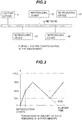
FIG. 4 is a diagram showing an example of the packet structure of a general TS stream. -
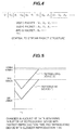
FIG. 5 is a diagram showing exemplary transitions of the remaining amount in the buffer memory of the reproducing device with the most advanced reproduction time and the reproducing device with the most delayed reproduction time in the video information reproducing system inFIG. 2 . -
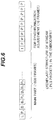
FIG. 6 is a diagram showing an example of the PES packet structure of MPEG data according to the first embodiment of the invention. -
FIG. 7 is a diagram showing an example of the packet structure of a TS stream according to the first embodiment. -
FIG. 8 is a diagram showing an example of the syntax of the synchronization adjustment packet inFIG. 7 . -
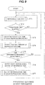
FIG. 9 is a flowchart illustrating the video information reproducing method according to the first embodiment of the invention. -
FIG. 10 is a flowchart showing details of step ST7 inFIG. 9 . -
FIG. 11 is a diagram illustrating the reproduction of different numbers of additional frames at each reproducing device for synchronization adjustment in the first embodiment of the invention. -
FIG. 12 is a diagram showing an example of the relationship between the decoding sequence and display sequence of ordinary MPEG-2 data. -
FIG. 13 is a diagram showing an example of the relationship between the decoding sequence and display sequence of the frames added for synchronization adjustment according to the first embodiment. -
FIG. 14 is a flowchart illustrating a video information reproducing method according to a second embodiment of the invention. -
FIG. 1 is a block diagram schematically showing an example of the structure of a video information reproducing device used to implement the video information reproducing method according to the first embodiment of the present invention. The video information reproducing device shown is a device for reproducing content data distributed via a network from a content server. -
FIG. 2 is an overall block diagram conceptually illustrating a video information reproducing system including the video information reproducing device inFIG. 1 and a content server. Data are distributed from thecontent server 41 to each reproducingdevice 42 via anetwork 43 configured as, for example, an Ethernet (registered trademark). The description that follows assumes that data are distributed on thenetwork 43 by broadcast distribution using UDP (User Datagram Protocol). - The reproducing
devices 42 shown inFIG. 2 are configured as shown, for example, inFIG. 1 . - The video information reproducing device shown in
FIG. 1 has a reproducingsection 10 as a means for reproducing data delivered from thecontent server 41 and aCPU 21 as a reproduction control means for executing control of the device as a whole. The reproducingsection 10 includes adata receiving unit 11 for receiving data distributed from thecontent server 41, abuffer memory 12 for temporarily storing the data received by thedata receiving unit 11, ademultiplexer 13 for separating data read from thebuffer memory 12 into audio and video information, avideo decoder 14 for decoding the video information, and anaudio decoder 15 for decoding the audio information. The video signal output from thevideo decoder 14 is sent to anexternal display device 31, by which a video picture is displayed. The audio signal output from theaudio decoder 15 is sent to an audio output device (not shown) for output of sound. - In this embodiment, it is assumed that data are delivered to the
data receiving unit 11 in a TS (Transport Stream). In this case, the video information and audio information are divided into PES (Packetized Elementary Stream) packets, and then further divided into TS packets, the video information and audio information being delivered in a multiplexed state. - In the PES packets, PES header information is added to an ES (Elementary Stream) that has been encoded according to MPEG-2, H.264, or the like. PES packets are packetized in units of reproduction time control; in the video information, for example, one image frame (picture) becomes one PES packet. The header information of a PES packet includes a time stamp such as, for example, a PTS (Presentation Time Stamp) that provides reproduction time information.
- A TS packet has a fixed length (188 bytes). A PID (Packet ID) unique to the data type is added to the header portion of each TS packet. The PID makes it possible to distinguish between video information, audio information, and system information (such as reproduction control information). The
demultiplexer 13 reads the PID, thereby distinguishes between video information and audio information, and assigns the data to the corresponding decoder. - Although this embodiment is described on the assumption of data divided into 188-byte TS packets, other (non-TS) data formats that enable video information to be distinguished from audio information may be used. When no audio information is provided and only video information data are delivered, the data may be delivered directly in a PES (Packetized Elementary Stream) without being divided into TS packets. In this case, the
demultiplexer 13 and theaudio decoder 15 in the reproducingsection 10 are unnecessary. - In the video information reproducing device in this embodiment, the
CPU 21 functions as a received data control means for constantly monitoring the capacity of thebuffer memory 12, thereby controlling thebuffer memory 12 to keep it from underflowing or overflowing. -
FIG. 3 is a diagram illustrating transitions in the capacity of thebuffer memory 12. TheCPU 21 constantly monitors the capacity of thebuffer memory 12 and keeps thecontent server 41 notified of the remaining capacity of thebuffer memory 12. - When the reproducing device performs reproduction in a state in which the
content server 41 is not transmitting data and as a result the amount of data remaining in thebuffer memory 12 diminishes to a lower limit (a first prescribed threshold value) SR1, thecontent server 41 starts (resumes) data transmission to the reproducingdevice 42; when the amount remaining in thebuffer memory 12 reaches an upper limit (a second prescribed threshold value) SR2, thecontent server 41 stops transmitting data to the reproducingdevice 42. - When the remaining space in the
buffer memory 12 again falls to the lower limit SR1, thecontent server 41 resumes data transmission. - By repetition of the above operations, data transmission is controlled so that the amount of data remaining in the
buffer memory 12 is kept between the upper limit SR2 and the lower limit SR1. - The
CPU 21 monitors the reproduction time of thevideo decoder 14 in the same reproducingdevice 42, notifies thecontent server 41 of the time, and also operates as a means of providing control by increasing or decreasing the size of the data transferred from thecontent server 41 to thebuffer memory 12 according to the time skew of thevideo decoder 14 in the same reproducingdevice 42 with respect to a reference reproduction time received from thecontent server 41. - The
content server 41 notifies each reproducingdevice 42 of the length of its skew from the reproduction time of the standard reproducingdevice 42. TheCPU 21 performs data control such that when the reproduction time of the reproducingdevice 42 leads the reproduction time of the standard reproducingdevice 42, a larger amount of the data received at thedata receiving unit 11 is stored in thebuffer memory 12, and when the reproduction time lags the reproduction time of the standard reproducingdevice 42, a smaller amount of data is stored in thebuffer memory 12. A detailed description of the control of the amount of data stored in thebuffer memory 12 will be given later. -
FIG. 4 is a diagram illustrating the structure of the TS data delivered from thecontent server 41. The audio and video information in the TS data are divided into 188-byte packets (TS packets), and video packets in which image data are stored, audio packets in which sound data are stored, and PSI/SI packets in which PAT, PMT, and other system information are stored are multiplexed to prevent audio or video reproduction from being interrupted. - Next, the sequence up to reproduction of the content delivered from the
content server 41 will be described. When a request for start of reproduction (a request for data transmission for reproduction) is output from the user to thecontent server 41, thecontent server 41 starts broadcast transmission of the TS data to each reproducingdevice 42. (The request for start of reproduction may be performed by sending a signal from one of the reproducing devices or may be given by separate control equipment (not shown).) - Each reproducing
device 42 receives the distributed TS data with itsdata receiving unit 11 and starts storing the data in thebuffer memory 12. At this time, thecontent server 41 arbitrarily selects a representative device among all the reproducingdevices 42, and constantly monitors the amount of data remaining in thebuffer memory 12 of the representative reproducingdevice 42. When thecontent server 41 detects that the amount remaining in thebuffer memory 12 has exceeded a third prescribed threshold value (initial reproduction starting value) SR3 that is greater than the lower limit value SR1 and smaller than the upper limit value SR2 inFIG. 3 , it commands all the reproducingdevices 42 to start reproduction (starting display and output at the reproducing devices). - When the reproduction command is issued from the
content server 41, in each reproducingdevice 42, the packets of TS data in thebuffer memory 12 are sent to thedemultiplexer 13, where the data are separated into video information, audio information, and PSI/SI information according to the PIDs of the corresponding packets. The separated video information is sent to thevideo decoder 14, from which a decoded video signal is output to theexternal display device 31. The separated audio information is sent to theaudio decoder 15, from which a decoded audio signal is sent to an audio output device (not shown) that outputs sound. Even after the reproduction of audio and video has started, as long as data transmission continues from thecontent server 41, the amount remaining in thebuffer memory 12 increases with time. However, the rate of increase is slower than when reproduction is not being performed in the reproducing device, so that the slope of the remaining amount curve decreases after the start of reproduction. - As described earlier, the
CPU 21 keeps thecontent server 41 notified of the amount remaining in thebuffer memory 12; when thecontent server 41 detects that the amount remaining in thebuffer memory 12 has reached the upper limit value SR2, it stops transferring data. - When data transfer is stopped, the amount remaining in the
buffer memory 12 of each of the reproducingdevices 42 gradually decreases as the data are consumed by the decoders. When thecontent server 41 detects that the amount remaining in thebuffer memory 12 in the representative reproducingdevice 42 has reached the lower limit value SR1, thecontent server 41 resumes data distribution. - By repeating the above operations, reproduction is continued without interrupting the picture or sound by causing the
buffer memory 12 to underflow or overflow. - However, in the last part of each item of content, even when the amount remaining in the
buffer memory 12 is detected to have reached the lower limit value SR1, since there are no more data to transmit, the remaining amount dwindles further and finally reaches zero, as indicated by dotted line inFIG. 3 . - The thresholds SR1, SR2, and SR3 should be set at appropriate values according to the capacity of the
buffer memory 12, the reproduction bit rate, etc., but values of these thresholds will not be particularly mentioned since they do not relate directly to this application. - With this procedure, reproduction is started concurrently at all the reproducing
devices 42, but the oscillation frequencies of the crystal oscillators in theclock circuits 22, which generate reference times for thevideo decoders 14, are not exactly the same: there are differences among the oscillator frequencies in the reproducingdevices 42. The output time of the decoded video data is controlled according to the PTS (included in the header information of the PES packets) in the video information based on the reference times. Specifically, each PES image is reproduced and output at a time (a relative time from the start of reproduction of the content) designated by the PTS included in the header information of the PES, while decoding and time adjustment (delay) are performed, by detecting that the time (the time relative to the time of reproduction of the top of the content) designated by the PTS included in the header information of the PES has been reached, by comparison with the result of counting clock pulses generated by the crystal oscillator in the reproducingdevice 42. The reproduction time skew mentioned above means the difference between the time at which reproduction of a PES packet including a PTS is timed by theclock circuit 22 in one reproducing device and the time at which the reproduction of a PES packet including the same PTS is timed by theclock circuit 22 in another reproducing device. - Because of the above configuration, over time, the reproduction times of the reproducing
devices 42 come to differ due to frequency error in their crystal oscillators. For example, given that the accuracy of the crystal oscillators is ±20 ppm, there is a difference of 40 ppm between a reproducingdevice 42 with the fastest display and a reproducingdevice 42 with the slowest display, and if reproduction takes place continuously for twenty-four hours, a time skew of about three seconds can occur. - In addition, since the
content server 41 controls data distribution by taking one of all the reproducingdevices 42, as a representative device, and monitoring the data remaining in thebuffer memory 12 in the representative device, if the reproducingdevice 42 with the largest error is taken as the representative device, the likelihood of occurrence of underflow and overflow in thebuffer memories 12 of the other reproducingdevices 42 becomes high. -
FIG. 5 is a diagram showing the transitions of the amounts remaining in the buffer memory of the reproducing device (F) with the time that runs the fastest and the reproducing device (S) with the time that runs the slowest when the reproducingdevice 42 with the time that runs the fastest is selected as the representative device. Thecontent server 41 resumes data distribution when the amount remaining in the fastest reproducing device (F) reaches the lower limit value SR1 at time T1; at this time, the slowest reproducing device (S) has more remaining data. - For example, with a video encoding bit rate of 10 Mbps, because of the above time skew, 3.5 Mbits more data remain in reproducing device (S) than in reproducing device (F).
- If the capacity of the
buffer memory 12 is 10 Mbits, the lower limit value SR1 is 3 Mbits, and the upper limit value SR2 is 6 Mbits, then when the amount remaining in reproducing device (F) is 6 Mbits, the amount remaining in reproducing device (S) is 9.5 Mbits, which approaches the limit capacity of the buffer memory, so that if reproduction (data transmission therefor) continues further, data to be reproduced will be discarded when the capacity of thebuffer memory 12 of reproducing device (S) is exceeded, and accordingly a video picture with some frames missing will be displayed. - As described above, there has been the problem that because of differences in the frequencies of the crystal oscillators, prolonged continuation of reproduction causes loss of synchronization of the displays of the different video information display devices, leading in the worst case to overflow or underflow of the buffer memories and interruption or suspension of reproduction.
-
FIG. 6 is a diagram showing an exemplary improved PES packet sequence of video information for implementing the video information reproducing method according to the first embodiment of the invention. - Among the PES packets, those with reference character 'I' include I-picture, those with reference character 'P' include P-pictures, and those with reference character 'B' include B-pictures. The subscripts '1', '2', '3', etc. attached to the reference characters 'T', 'P', '13' are used to distinguish individual I-, P-, and B-pictures and also indicate the order of reproduction.
- An I-picture is image information that has been encoded intra-frame (intra-frame encoded image information) and can be decoded independently. A P-picture is image information (inter-frame forward prediction encoded image information) that has been encoded by forward motion-compensating prediction with reference to a preceding picture (an I-picture or another P-picture); a B-picture is image information (inter-frame bidirectional prediction encoded image) that has been encoded by bidirectional motion-compensating prediction with reference to preceding and following pictures (I-pictures, P-pictures, or other B-pictures).
- Here, if the reproduction time of the TS data is 60 seconds and the frame rate is 30 fps, there are 1800 (60 x 30 = 1800) PES packets of TS data in total, but in this embodiment, PES packets for a further ten frames are added for reproduction synchronization adjustment to the main part consisting of the above 1800 PES packets (the part included in the TS data even when the inventive synchronization adjustment is not performed), making a total of 1810 PES packets. The video images of the ten added frames are encoded to display the same video image as the video image in the final frame in the 60 seconds repetitively. The (group of) synchronization adjustment frames in the example shown include I-picture data for one frame consisting of the same video data as the video data of the last frame and P-picture data for nine frames that continuously display the same video image.
- Such added synchronization adjustment frames may be held in a pre-authored form in the
content server 41 or may be added on thecontent server 41 at the time of delivery by use of MPEG dummy pictures. - The first PES packet among the additional PES packets is an I-picture (for H.264, an IDR picture, which is also intra-frame encoded image information), and the subsequent PES packets include P-pictures or I-pictures (or IDR pictures) but not B-pictures. Because no B-pictures are included, the display sequence of the pictures for the ten added synchronization adjustment frames matches their data sequence. In, for example, the leading portion of the TS data in
FIG. 6 , however, the PES packet sequence is 'I1', 'P1', 'B1' and 'B2', but the actual display sequence is 'I1', `B1' , 'B2' and 'P1', so that the display sequence differs from the data sequence. -
FIG. 7 is a diagram showing the improved TS data packet sequence for implementing the video information reproducing method according to the embodiment. The difference from the TS data inFIG. 4 is the multiplexing of an adjustment information packet in which adjustment packet information indicating how many packets there are from the head of the TS data to the first TS packet among the PES packets of the ten additional frames. -
FIG. 8 is a diagram illustrating the syntax of the synchronization adjustment packet. The 'num_of_PES' parameter indicates the total number of PES packets (frames) added to the main data and available for synchronization adjustment. The following loop is repeated the number of times indicated by 'num_of_PES'. If there are ten frames, 'num_of_PES' = 10. - 'PTS_for_adjust(i)' indicates the PTS value at the head of each PES packet available for synchronization adjustment.
- 'SPN_for_adjust(i)' is a value indicating how many packets there are from the start of the TS data to the TS packet that includes the PES packet header with the value indicted by 'PTS_for_adjust(i)'.
- Although the adjustment packet information is sent to the reproducing
device 42 multiplexed with the TS packets in this embodiment, it need not necessarily be multiplexed with the TS packets; the adjustment packet information may be sent to the reproducingdevice 42 in an independent command. - In the
content server 41 there are a plurality of TS data streams structured as inFIG. 7 , which are delivered continuously to the reproducingdevices 42. When a reproduction command is output from the user to thecontent server 41, thecontent server 41 starts delivering the TS data in a pre-instructed order. - In normal reproduction, from the adjustment information packet data included in the TS data, the
CPU 21 anticipates the arrival of the TS packets including the PES packets of the additional ten frames and discards the TS packets from SPN_for_adjust(0) onward without storing them in thebuffer memory 12. -
FIG. 9 is a flowchart illustrating a processing sequence for synchronizing reproduction among the reproducingdevices 42. Steps ST5 and ST6 indicate processing in thecontent server 41; the other steps indicate processing in the reproducingdevice 42. - During normal reproduction, when the reproduction of the main content is completed, the ten frames added as described above are not displayed (ST1). As described above, the crystal oscillator frequency accuracy is about 20 ppm, at which level loss of synchronization is not visible after only several minutes of reproduction. About once every several tens of minutes, i.e., whenever a prescribed time has elapsed (ST2), a check of the current reproduction time of each reproducing
device 42 is made from the content server 41 (ST3). - In response to the check of the reproduction time from the
content server 41, each reproducingdevice 42 notifies thecontent server 41 of its current reproduction time (ST4). - The
content server 41 collates the reported time data and decides whether a synchronization adjustment of the reproduction times is necessary or not (ST5). For that purpose, it determines whether the difference between the most advanced reproduction time and the least advanced reproduction time is equal to or greater than a prescribed value: for example, equal to or greater than one frame. - If the reproduction time difference is equal to or greater than one frame and an adjustment is determined to be necessary, a reproducing
device 42 with an average reproduction time is used as areference reproducing device 42 and its reproduction time is sent to all the other reproducingdevices 42 as a reference time (ST6). - Each reproducing
device 42 that receives the reference time recognizes, from the difference between the reproduction time it reported earlier and the reference time sent from thecontent server 41, whether its reproduction is running ahead of or behind thereference reproducing device 42 and adjusts its reproduction time (ST7). - The reproducing
device 42 determines whether or not the difference from the reference reproduction time sent by thecontent server 41 is equal to or less than one frame; if the reproduction time difference is within one frame, it reproduces the first five frames of the ten frames added for synchronization adjustment, and theCPU 21 discards the data from SPN_for_adjust (5) onward. Therefore, the total reproduction time of the TS data currently being reproduced corresponds to the main data plus five frames, and the last frame of the main data is displayed repeatedly for the last six frames. After the first five added frames have been reproduced, reproduction continues with the TS data of the next content. -
FIG. 10 is a diagram illustrating details of the adjustment sequence in step ST7 inFIG. 9 . First, whether or not reproduction lags the reproduction time (reference time) of thereference reproducing device 42 by one frame or more is determined (ST8). - A reproducing
device 42 that determines that it lags the reference time by one frame or more then calculates the lag time from the reference time and its own reproduction time, calculates the number of frames corresponding to the lag time, and subtracts the number of frames corresponding to the lag time from five frames, thereby calculating the amount of data to store in thebuffer memory 12. For example, if the lag time is 60 msec (corresponding to two frames), only the first three of the ten frames added at the end of the TS data are stored in thebuffer memory 12, and the data from SPN_for__adjust(3) onward are discarded (ST9). - As a result, the total reproduction time of the TS data currently being reproduced corresponds to the main data plus three frames, and the last frame of the main data is displayed repeatedly during the last four frames. After the first three added frames are reproduced, reproduction continues with the TS data of the next content.
- In step ST10, whether or not the reproduction time leads the reproduction time of the
reference reproducing device 42 by one frame or more is determined. A reproducingdevice 42 that determines that it leads the reference time by one frame or more then calculates the lead time from the reference time and its own reproduction time, calculates the number of frames corresponding to the lead time, and adds the number of frames corresponding to the lead time to five frames, thereby calculating the amount of data to store in the buffer memory 12 (ST11). For example, if the lead time is 90 msec (corresponding to three frames), only the first eight of the ten frames added at the end of the TS data are stored in thebuffer memory 12, and the data from SPN_for_adjust(8) onward are discarded. Accordingly, the total reproduction time of the TS data currently being reproduced corresponds to the main data plus eight frames, and the last frame of the main data is displayed repeatedly during the last nine frames. After the first eight added frames are reproduced, reproduction continues with the TS data of the next content. - In step ST10, if the reproducing
device 42 determines that the lead time is within one frame, it reproduces the first five frames in the ten frames added to the end of the TS data and discards the data from SPN_for_adjust(5) onward (ST12). Accordingly, the total reproduction time of the TS data currently being reproduced corresponds to the main data plus five frames and the last frame of the main data is displayed repeatedly for the last six frames. After the first five added frames are reproduced, reproduction continues with the TS data of the next content. - In the above example, the total reproduction time for the content currently being reproduced by the reproducing
device 42 that lags the reference time is two frames shorter than that of thereference reproducing device 42; the total reproduction time for the content currently being reproduced by the reproducingdevice 42 that leads the reference time is three frames more than that of thereference reproducing device 42. -
FIG. 11 is a diagram illustrating transitions in reproduction time of the reproducingdevices 42 around a switch in content. When reproduction is performed according to the above sequence, the reproducingdevice 42 that lags the reference time makes the total reproduction time of the TS data it is currently reproducing shorter than thereference reproducing device 42 by the length of the lag, while the reproducingdevice 42 that leads the reference time makes the total reproduction time of TS data it is currently reproducing longer than thereference reproducing device 42 by the length of the lead, whereby the starting timings of the reproduction the TS data of the next content can be aligned to within a difference of one frame or less. - In order to make the reproduction time of TS data adjustable with high precision at each reproducing
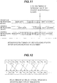
device 42 as above, some constraints are necessary on the added adjustment TS data.FIG. 12 is a diagram illustrating a typical sequence of MPEG frames. In this case, data are delivered in the sequence 'I1', P1', 'B1', 'B2', ... from thecontent server 41, but the display sequence is 'I1', 'B1', 'B2', 'P1',.... If the added data were to be arranged as inFIG. 12 , to reproduce up to 'B1', the data of four frames 'I1', 'P1', 'B1', and 'B2' would have to be input to thebuffer memory 12. Thevideo decoder 14 would reproduce the four frames of 'I1', 'B1' 'B2', and 'P1', exceeding the intended number of displayed frames by two frames. - The four frames of 'I1', 'B1', 'B2', and 'P1' would similarly be reproduced when display up to 'B2' was intended or when display up to 'P1' was intended. Thus if the encoding is carried out so as to include B frames, an error of up to two frames occurs in the case shown in
FIG. 12 , resulting in lowered synchronization accuracy. -
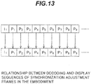
FIG. 13 shows a frame sequence designed for synchronization with one-frame precision. UnlikeFIG. 12 , encoding is performed without using B frames. This encoding provides a match between the frame sequence and reproduction sequence. Accordingly, to reproduce only three frames, the data of the three frames 'I1', 'P1', and 'P2' can be stored in the buffer memory and the subsequent frames can be discarded. Synchronization adjustment with frame precision is thus possible by not using B frames. Encoding without using B frames lowers the encoding efficiency, however, so that to obtain the same image quality as obtained by use of B frames, the data size must increase. In order to avoid this, it is preferable to encode the main part by using B frames and encode the adjustment frames without using B frames, but encoding the main data and adjustment frames with mutually different rules is also problematic in that the encoding becomes more complicated. Therefore, the adjustment frames are preferably encoded without using B frames in a system requiring precise synchronization, and are preferably encoded by use of B frames when high synchronization precision is not required. - As described above, by using TS data with reproduction time synchronization adjustment frames added at the end to adjust the amount of TS data added for synchronization adjustment that is stored in the buffer memory based on the information about reproduction time difference relative to the reproduction time of the
reference reproducing device 42, it becomes possible to synchronize reproduction with high precision among the display devices. - In the description of this embodiment, the reproduction time of the reproducing
device 42 with the value closest to the mean value of the reproduction times of all the reproducingdevices 42 is set as the reference time, but it need not be the closest to the mean value; instead, it may be the median value, for example, or exactly the same effect may be obtained by setting the reproducingdevice 42 with the most advanced reproduction time as the reference, having the reproducingdevice 42 with the most advanced reproduction time reproduce all ten added frames, and having the other reproducingdevices 42 reproduce numbers of additional frames reduced from ten frames according to the size of the deviation from the reference reproduction time. Similarly, exactly the same effect is also obtainable by setting the reproducingdevice 42 with the most delayed reproduction time as the reference, having the reproducingdevice 42 with the most delayed reproduction time reproduce no added frames, and having the other reproducingdevices 42 reproduce numbers of frames that increase according to the size of the deviation from the reference reproduction time. - The present invention is applicable to, for example, display devices that perform displays on multiple screens in automobiles, trains, buildings, or the like, producing the effect of enabling the reproduction times of a plurality of display devices to be synchronized with high precision.
- The adjustment method described in the first embodiment is for a case in which the variation in reproduction time among the reproducing
devices 42 stays within the range of the number of frames provided for adjustment. However, there are cases in which reproduction becomes greatly out of synchronization because theCPU 21 in a reproducingdevice 42 experiences a sudden load, or the reproducingdevice 42 experiences electrical noise and is reset, and data delivery from thecontent server 41 starts before preparations for reproduction can be made. In these cases, the time skew becomes as long as several seconds, so that synchronization by the adjustment method in the first embodiment might take several tens of minutes to several hours to achieve. -
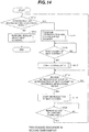
FIG. 14 illustrates an improved sequence for performing adjustments in a short time in such cases, when there is substantial reproduction time skew. Steps ST18 and ST19 inFIG. 14 illustrate processing performed in thecontent server 41; the other steps illustrate processing in the reproducingdevices 42. - First, whether or not the amount of deviation from the reproduction time of the
reference reproducing device 42 is within the synchronizable range (within the range adjustable by the method described in the first embodiment) is determined (ST13). - If the deviation is determined to be within the synchronizable range, the process proceeds to step ST14, in which the regular adjustment (the adjustment described with reference to
FIG. 10 ) is performed. Details of the adjustment in step ST14 will be omitted since they were given in the first embodiment. - If the amount of reproduction time deviation is determined to be outside the synchronizable range, the reproduction currently being performed is suspended and all data stored in the
buffer memory 12 are cleared (ST15). - A reproducing
device 42 in which reproduction is suspended waits for the completion of the delivery of the TS data of the content currently being reproduced and the arrival of the first TS packet of the next content (ST16). Upon detection of the first TS packet of the next content, theCPU 21 starts storing the data in the buffer memory 12 (ST717). - Next, the
content server 41 commands thereference reproducing device 42 to notify thecontent server 41 when it starts reproduction of the first frame of the next content; when notified from thereference reproducing device 42 that reproduction of the next content has started (ST18), thecontent server 41 issues a reproduction start command to the reproducingdevice 42 in which reproduction was suspended (ST19), and the reproduction of content is resumed in the reproducingdevice 42 in which reproduction was suspended. - There are delays in having the
content server 41 notified of the start of reproduction from thereference reproducing device 42 and delays until the reproducingdevice 42 in which the reproduction was suspended receives the reproduction start command from thecontent server 41, including network delays and delays due to software processing time, and there is a delay from the issuing of the reproduction command to thevideo decoder 14 until the first frame is displayed, so that at this point in time, the reproduction time of the reproducingdevice 42 in which reproduction was suspended is in a state that lags the other reproducingdevices 42 by several frames. This lag, however, is within the range adjustable by the regular synchronization adjustment sequence, so that synchronization can be achieved in the next adjustment sequence. - As described above, a reproducing
device 42 with a badly skewed reproduction time can be brought into synchronization at the adjustment of the next content by suspending reproduction and then resuming reproduction at the timing at which thereference reproducing device 42 starts reproduction of the first frame of the next content. - The present invention is applicable to, for example, display devices that perform displays on multiple screens in automobiles, trains, buildings, or the like, producing the effect of enabling the reproduction times of a plurality of display devices to be synchronized in a short time.
- 10 reproducing section, 11 data receiving unit, 12 buffer memory, 13 demultiplexer, 14 video decoder, 15 audio decoder, 21 CPU (discrimination means, reproduction control means), 31 external display device, 41 content server, 42 reproducing device, 43 network.
Claims (12)
- A video information reproduction method for receiving content formed by a sequence including at least intra-frame encoded image information and inter-frame forward prediction encoded image information, and including time stamp information, delivered from a content server (41) connected by a network (43), at a plurality of video information reproducing devices (42) and decoding and reproducing the content at the video information reproducing devices (42), at a time designated by the time stamp information, according to clock pulses generated by a crystal oscillator, the video information reproduction method comprising:a reproduction time reporting step performed by each of the video information reproducing devices (42) for reporting, to the content server (41), the reproduction time at which the content has been reproduced according to the clock pulses;a reference reproduction time notifying step performed by the content server (41) for selecting, based on the reproduction time reported by each of the video information reproducing devices (42), a reference video information reproducing device (42) from among the plurality of video information reproducing devices (42), and setting the reproduction time reported by the reference video information reproducing device (42) as a reference reproduction time and notifying each of the video information reproducing devices (42) of the reference reproduction time;a detection step performed by each of the video information reproducing devices (42) for comparing the reproduction time reported by said each of the video information reproducing devices (42), and the reference reproduction time notified by the content server (41), and detecting a difference between the reproduction time reported by said each of the video information reproducing devices (42), and the reference reproduction time notified by the content server (41);wherein the content comprises frames constituting a main part formed by a sequence including at least intra-frame encoded image information and inter-frame forward prediction encoded image information, and synchronization adjustment frames consisting of a sequence including at least intra-frame encoded image information and inter-frame forward prediction encoded image information, and encoded to display video of the same content as in a last frame in the main part; and wherein the method further comprises:an adjustment step performed by each of the video information reproducing devices (42) for adjusting the number of synchronization adjustment frames to be reproduced, when the reproduction time reported by said each of the video information reproducing devices (42) lags the reference reproduction time, by subtracting a number of synchronization adjustment frames to be reproduced from a number of synchronization adjustment frames to be reproduced by the reference video information reproducing device (42) according to the lag time, and when the reproduction time reported by said each of the video information reproducing devices (42) leads the reference reproduction time, by adding a number of synchronization adjustment frames to be reproduced to the number of synchronization adjustment frames to be reproduced by the reference video information reproducing device (42) according to the lead time.
- The video information reproduction method of claim 1 wherein, in the step for detecting the difference, the content server (41) collates reproduction times reported from each of the video information reproducing devices (42) and selects a video information reproducing device (42) with a reproduction time closest to an average value to be the reference.
- The video information reproduction method of claim 1 wherein, in the step for detecting the difference, the content server (41) collates reproduction times reported from each of the video information reproducing devices (42) and selects a video information reproducing device (42) with the most delayed reproduction time to be the reference.
- The video information reproduction method of claim 1 wherein, in the step for detecting the difference, the content server (41) collates reproduction times reported from each of the video information reproducing devices (42) and selects a video information reproducing device (42) with the most advanced reproduction time to be the reference.
- The video information reproduction method of claim 1, further comprising:a decision step performed by each of said video information reproducing devices for deciding whether the difference detected in the detection step is within a range synchronizable by the adjustment made in the adjustment step;a discarding step performed by each of said video information reproducing devices for, when the difference is decided in the decision step not to be within the synchronizable range, suspending reproduction of the content currently being reproduced and discarding the data of the content stored in a buffer memory;a storage step performed by each of said video information reproducing devices for storing, when the video information reproducing device (42) which is suspending the reproduction, beginning when the next content is received, the data of the content in the buffer memory; anda start control step performed by each of said video information reproducing devices for starting, when the video information reproducing device (42) which is suspending the reproduction is notified by the content server (41) of a timing at which the reference video information reproducing device (42) has started reproduction of the next content, reproduction of the next content on reception of such notification.
- The video information reproduction method of any one of claims 1 to 5, wherein the intra-frame encoded image information and inter-frame forward encoded image information are MPEG-2 or H.264 encoded information.
- A video information reproduction system having a content server for delivering content formed by a sequence including at least intra-frame encoded image information and inter-frame forward prediction encoded image information, and including time stamp information, and a plurality of video information reproducing devices connected to the content server (41) by a network (43), for receiving the content delivered from the content server and decoding and reproducing the content at the video information reproducing devices (42), at a time designated by the time stamp information, according to clock pulses generated by a crystal oscillator, wherein
each of the plurality of video information reproducing devices comprises a means for reporting, to the content server (41), the reproduction time at which the content has been reproduced according to the clock pulses;
the content server selects, based on the reproduction time reported by each of the video information reproducing devices (42),a video reference information reproducing device (42) from among the plurality of video information reproducing devices (42), and sets the reproduction time reported by the reference video information reproducing device (42) as a reference reproduction time and notifies each of the video information reproducing devices (42) of the reference reproduction time;
each of the video information reproducing devices (42) also comprises:a means for comparing the reproduction time reported by said each of the video information reproducing devices (42), and the reference reproduction time notified by the content server (41), and detecting a difference between the reproduction time reported by said each of the video information reproducing devices (42), and the reference reproduction time notified by the content server (41), andwherein the content comprises frames constituting a main part formed by a sequence including at least intra-frame encoded image information and inter-frame forward prediction encoded image information, and synchronization adjustment frames consisting of a sequence including at least intra-frame encoded image information and inter-frame forward prediction encoded image information, and encoded to display video of the same content as in a last frame in the main part, the system further comprising:a means for adjusting the number of synchronization adjustment frames to be reproduced, when the reproduction time reported by said each of the video information reproducing devices (42) lags the reference reproduction time, by subtracting a number of synchronization adjustment frames to be reproduced from a number of synchronization adjustment frames to be reproduced by the reference video information reproducing device (42) according to the lag time, and when the reproduction time reported by said each of the video information reproducing devices (42) leads the reference reproduction time, by adding a number of synchronization adjustment frames to be reproduced to the number of synchronization adjustment frames to be reproduced by the reference video information reproducing device (42) according to the lead time. - The video information reproduction system of claim 7 wherein, in the means for detecting the difference, the content server (41) collates reproduction times reported from each of the video information reproducing devices (42) and selects a video information reproducing device (42) with a reproduction time closest to an average value to be the reference.
- The video information reproduction system of claim 7 wherein, in the means for detecting the difference, the content server (41) collates reproduction times reported from each of the video information reproducing devices (42) and selects a video information reproducing device (42) with the most delayed reproduction time to be the reference.
- The video information reproduction system of claim 7 wherein, in the means for detecting the difference, the content server (41) collates reproduction times reported from each of the video information reproducing devices (42) and selects a video information reproducing device (42) with the most advanced reproduction time to be the reference.
- The video information reproduction system of claim 7, wherein each of the video information reproducing devices further comprises:a decision means for deciding whether the difference detected in the detection means is within a range synchronizable by the adjustment made by the adjustment means;a discarding means for, when the difference is decided by the decision means not to be within the synchronizable range, suspending reproduction of the content currently being reproduced and discarding the data of the content stored in a buffer memory;a storage means for storing, when the video information reproducing device (42) which is suspending the reproduction, beginning when the next content is received, the data of the content in the buffer memory; anda start control means for starting, when the video information reproducing device (42) which is suspending the reproduction is notified by the content server (41) of a timing at which the reference video information reproducing device (42) has started reproduction of the next content, reproduction of the next content on reception of such notification.
- The video information reproduction system of any one of claims 7 to 11, wherein the intra-frame encoded image information and inter-frame forward encoded image information are MPEG-2 or H.264 encoded information.
Applications Claiming Priority (2)
| Application Number | Priority Date | Filing Date | Title |
|---|---|---|---|
| JP2009270330A JP5489675B2 (en) | 2009-11-27 | 2009-11-27 | Video information playback method and system, and video information content |
| PCT/JP2010/002707 WO2011064909A1 (en) | 2009-11-27 | 2010-04-14 | Method and system for playing video information, and video information content |
Publications (3)
| Publication Number | Publication Date |
|---|---|
| EP2506570A1 EP2506570A1 (en) | 2012-10-03 |
| EP2506570A4 EP2506570A4 (en) | 2013-08-21 |
| EP2506570B1 true EP2506570B1 (en) | 2017-08-23 |
Family
ID=44066024
Family Applications (1)
| Application Number | Title | Priority Date | Filing Date |
|---|---|---|---|
| EP10832765.1A Not-in-force EP2506570B1 (en) | 2009-11-27 | 2010-04-14 | Method and system for playing video information, and video information content |
Country Status (7)
| Country | Link |
|---|---|
| US (1) | US9066061B2 (en) |
| EP (1) | EP2506570B1 (en) |
| JP (1) | JP5489675B2 (en) |
| KR (1) | KR101443470B1 (en) |
| CN (1) | CN102640511B (en) |
| HK (1) | HK1171591A1 (en) |
| WO (1) | WO2011064909A1 (en) |
Families Citing this family (28)
| Publication number | Priority date | Publication date | Assignee | Title |
|---|---|---|---|---|
| KR101987756B1 (en) | 2012-07-24 | 2019-06-11 | 삼성전자주식회사 | Media reproducing method and apparatus thereof |
| JP5542892B2 (en) * | 2012-10-18 | 2014-07-09 | 株式会社東芝 | Content processing apparatus and content synchronization method |
| US8978076B2 (en) * | 2012-11-05 | 2015-03-10 | Comcast Cable Communications, Llc | Methods and systems for content control |
| JP6376526B2 (en) * | 2012-12-03 | 2018-08-22 | 株式会社コナミデジタルエンタテインメント | Output timing control device, output timing control system, output timing control method, and program |
| JP6051847B2 (en) * | 2012-12-25 | 2016-12-27 | 三菱電機株式会社 | Video information reproduction method and system |
| JP2015015706A (en) * | 2013-07-03 | 2015-01-22 | パナソニック インテレクチュアル プロパティ コーポレーション オブアメリカPanasonic Intellectual Property Corporation of America | Data transmission method, data reproduction method, data transmitter and data reproducer |
| EP2999260B1 (en) * | 2013-07-08 | 2018-08-29 | Huawei Technologies Co., Ltd. | Control method, device and system for video playing |
| US9800908B2 (en) | 2013-07-09 | 2017-10-24 | Koninklijke Kpn N.V. | Synchronized data processing of broadcast streams between receivers, including synchronized data processing between a receiver that is in the process of processing a stream and a receiver that wants to join the stream |
| KR20150033827A (en) * | 2013-09-24 | 2015-04-02 | 삼성전자주식회사 | Image display apparatus, server, and method for operating the same |
| KR20150037372A (en) * | 2013-09-30 | 2015-04-08 | 삼성전자주식회사 | Image display apparatus, Server for synchronizing contents, and method for operating the same |
| JP6510205B2 (en) * | 2013-10-11 | 2019-05-08 | パナソニック インテレクチュアル プロパティ コーポレーション オブ アメリカPanasonic Intellectual Property Corporation of America | Transmission method, reception method, transmission apparatus and reception apparatus |
| JP6136993B2 (en) * | 2014-03-05 | 2017-05-31 | 三菱電機株式会社 | Video information playback system, video information display system including the video information playback system, and in-vehicle video playback device provided in the video information playback system |
| CN104822008B (en) * | 2014-04-25 | 2019-01-08 | 腾讯科技(北京)有限公司 | video synchronization method and device |
| EP3151577B1 (en) * | 2014-05-28 | 2019-12-04 | Sony Corporation | Information processing apparatus, information processing method, and program |
| KR102336709B1 (en) | 2015-03-11 | 2021-12-07 | 삼성디스플레이 주식회사 | Tiled display device and syncronizing method thereof |
| US20160295256A1 (en) * | 2015-03-31 | 2016-10-06 | Microsoft Technology Licensing, Llc | Digital content streaming from digital tv broadcast |
| US10021438B2 (en) | 2015-12-09 | 2018-07-10 | Comcast Cable Communications, Llc | Synchronizing playback of segmented video content across multiple video playback devices |
| US11165683B2 (en) * | 2015-12-29 | 2021-11-02 | Xilinx, Inc. | Network interface device |
| US11044183B2 (en) | 2015-12-29 | 2021-06-22 | Xilinx, Inc. | Network interface device |
| JP6623888B2 (en) * | 2016-03-29 | 2019-12-25 | セイコーエプソン株式会社 | Display system, display device, head-mounted display device, display control method, display device control method, and program |
| WO2018088784A1 (en) | 2016-11-09 | 2018-05-17 | Samsung Electronics Co., Ltd. | Electronic apparatus and operating method thereof |
| CN110557675A (en) * | 2018-05-30 | 2019-12-10 | 北京视连通科技有限公司 | Method for analyzing, labeling and time base correcting video program content |
| JP7229696B2 (en) * | 2018-08-02 | 2023-02-28 | キヤノン株式会社 | Information processing device, information processing method, and program |
| KR102650340B1 (en) * | 2019-06-07 | 2024-03-22 | 주식회사 케이티 | Video play device, method and server for controlling reproduction time |
| KR20210087273A (en) * | 2020-01-02 | 2021-07-12 | 삼성전자주식회사 | Electronic apparatus and control method thereof |
| CN112153445B (en) * | 2020-09-25 | 2022-04-12 | 四川湖山电器股份有限公司 | Synchronous decoding and playing method and system for distributed video display system |
| CN112675531A (en) * | 2021-01-05 | 2021-04-20 | 深圳市欢太科技有限公司 | Data synchronization method and device, computer storage medium and electronic equipment |
| US11968417B2 (en) * | 2021-12-30 | 2024-04-23 | Comcast Cable Communications, Llc | Systems, methods, and apparatuses for buffer management |
Citations (2)
| Publication number | Priority date | Publication date | Assignee | Title |
|---|---|---|---|---|
| EP0897245A2 (en) * | 1997-08-13 | 1999-02-17 | Sarnoff Corporation | MPEG frame processing method and apparatus |
| US6324217B1 (en) * | 1998-07-08 | 2001-11-27 | Diva Systems Corporation | Method and apparatus for producing an information stream having still images |
Family Cites Families (12)
| Publication number | Priority date | Publication date | Assignee | Title |
|---|---|---|---|---|
| US6061399A (en) * | 1997-05-28 | 2000-05-09 | Sarnoff Corporation | Method and apparatus for information stream frame synchronization |
| US6507616B1 (en) * | 1998-10-28 | 2003-01-14 | Lg Information & Communications, Ltd. | Video signal coding method |
| JP2005244605A (en) * | 2004-02-26 | 2005-09-08 | Nippon Telegr & Teleph Corp <Ntt> | Streaming content distribution control system, program and recording medium storing the same |
| JP4039417B2 (en) | 2004-10-15 | 2008-01-30 | 株式会社日立製作所 | Recording / playback device |
| JP4457349B2 (en) * | 2005-03-31 | 2010-04-28 | 日本電気株式会社 | MPEG content synchronous playback method, client terminal, and MPEG content synchronous playback program |
| EP1879387A4 (en) | 2005-04-20 | 2013-03-06 | Panasonic Corp | Stream data recording device, stream data editing device, stream data reproducing device, stream data recording method, and stream data reproducing method |
| JP2008096756A (en) | 2006-10-12 | 2008-04-24 | Sharp Corp | Multi-screen display system and display method thereof |
| JP4967945B2 (en) * | 2007-09-13 | 2012-07-04 | ヤマハ株式会社 | Terminal device and data distribution system |
| JP2009081654A (en) * | 2007-09-26 | 2009-04-16 | Nec Corp | Stream synchronous reproduction system and method |
| US20090213777A1 (en) | 2008-02-27 | 2009-08-27 | Sanyo Electric Co., Ltd. | Distribution apparatus and receiving apparatus for reproducing predetermined contents |
| JP2009205396A (en) * | 2008-02-27 | 2009-09-10 | Sanyo Electric Co Ltd | Distribution device and receiving device |
| KR20120080122A (en) * | 2011-01-06 | 2012-07-16 | 삼성전자주식회사 | Apparatus and method for encoding and decoding multi-view video based competition |
-
2009
- 2009-11-27 JP JP2009270330A patent/JP5489675B2/en not_active Expired - Fee Related
-
2010
- 2010-04-14 CN CN201080053315.2A patent/CN102640511B/en not_active Expired - Fee Related
- 2010-04-14 KR KR1020127013418A patent/KR101443470B1/en active IP Right Grant
- 2010-04-14 EP EP10832765.1A patent/EP2506570B1/en not_active Not-in-force
- 2010-04-14 WO PCT/JP2010/002707 patent/WO2011064909A1/en active Application Filing
- 2010-04-14 US US13/498,243 patent/US9066061B2/en not_active Expired - Fee Related
-
2012
- 2012-11-26 HK HK12112071.3A patent/HK1171591A1/en not_active IP Right Cessation
Patent Citations (2)
| Publication number | Priority date | Publication date | Assignee | Title |
|---|---|---|---|---|
| EP0897245A2 (en) * | 1997-08-13 | 1999-02-17 | Sarnoff Corporation | MPEG frame processing method and apparatus |
| US6324217B1 (en) * | 1998-07-08 | 2001-11-27 | Diva Systems Corporation | Method and apparatus for producing an information stream having still images |
Also Published As
| Publication number | Publication date |
|---|---|
| KR20120068048A (en) | 2012-06-26 |
| US20120207215A1 (en) | 2012-08-16 |
| JP2011114681A (en) | 2011-06-09 |
| EP2506570A1 (en) | 2012-10-03 |
| EP2506570A4 (en) | 2013-08-21 |
| JP5489675B2 (en) | 2014-05-14 |
| US9066061B2 (en) | 2015-06-23 |
| CN102640511A (en) | 2012-08-15 |
| HK1171591A1 (en) | 2013-03-28 |
| CN102640511B (en) | 2014-11-19 |
| KR101443470B1 (en) | 2014-09-22 |
| WO2011064909A1 (en) | 2011-06-03 |
Similar Documents
| Publication | Publication Date | Title |
|---|---|---|
| EP2506570B1 (en) | Method and system for playing video information, and video information content | |
| JP3925311B2 (en) | Data distribution system | |
| US6101195A (en) | Timing correction method and apparatus | |
| US7298741B2 (en) | Robust MPEG-2 multiplexing system and method using an adjustable time stamp | |
| US6330286B1 (en) | Flow control, latency control, and bitrate conversions in a timing correction and frame synchronization apparatus | |
| US6785289B1 (en) | Method and apparatus for aligning sub-stream splice points in an information stream | |
| CA2234328C (en) | Method and apparatus for information stream frame synchronization | |
| US8189679B2 (en) | Content receiving apparatus, method of controlling video-audio output timing and content providing system | |
| US6449352B1 (en) | Packet generating method, data multiplexing method using the same, and apparatus for coding and decoding of the transmission data | |
| KR100981378B1 (en) | Device and process for the read-synchronization of video data and of ancillary data and associated products | |
| JP6051847B2 (en) | Video information reproduction method and system | |
| JP2007258932A (en) | Packet transmission system | |
| JPH11215083A (en) | Device and method for digital signal multiplex, device and method for digital signal transmission, device and method for digital signal recording, and recording medium thereof | |
| US20040170199A1 (en) | Method and system for compensating for timing violations of a multiplex of at least two media packet streams | |
| JP4192766B2 (en) | Receiving apparatus and method, recording medium, and program | |
| JP4224749B2 (en) | COMMUNICATION DEVICE, COMMUNICATION METHOD, AND RECORDING MEDIUM | |
| JP2002152273A (en) | Delay fluctuation absorbing method and packet arrangement adjustment device | |
| US20050265369A1 (en) | Network receiving apparatus and network transmitting apparatus | |
| JP3741972B2 (en) | Data recording / reproducing device | |
| JP4874272B2 (en) | Video signal processing apparatus and video signal processing method | |
| JP2012016066A (en) | Video signal processor, and video signal processing method | |
| JP2004266599A (en) | Transmitting side terminal and receiving side terminal | |
| JP2004158921A (en) | Data transmitter and data receiver | |
| JP2003284069A (en) | Method and apparatus for decoding multiple data |
Legal Events
| Date | Code | Title | Description |
|---|---|---|---|
| PUAI | Public reference made under article 153(3) epc to a published international application that has entered the european phase |
Free format text: ORIGINAL CODE: 0009012 |
|
| 17P | Request for examination filed |
Effective date: 20120322 |
|
| AK | Designated contracting states |
Kind code of ref document: A1 Designated state(s): AT BE BG CH CY CZ DE DK EE ES FI FR GB GR HR HU IE IS IT LI LT LU LV MC MK MT NL NO PL PT RO SE SI SK SM TR |
|
| DAX | Request for extension of the european patent (deleted) | ||
| A4 | Supplementary search report drawn up and despatched |
Effective date: 20130723 |
|
| RIC1 | Information provided on ipc code assigned before grant |
Ipc: H04N 21/44 20110101ALI20130717BHEP Ipc: H04N 21/8547 20110101ALI20130717BHEP Ipc: H04N 21/6405 20110101ALI20130717BHEP Ipc: H04N 21/6332 20110101AFI20130717BHEP Ipc: H04N 21/432 20110101ALI20130717BHEP Ipc: H04N 21/43 20110101ALI20130717BHEP Ipc: H04N 21/242 20110101ALI20130717BHEP |
|
| 17Q | First examination report despatched |
Effective date: 20140331 |
|
| REG | Reference to a national code |
Ref country code: DE Ref legal event code: R079 Ref document number: 602010044721 Country of ref document: DE Free format text: PREVIOUS MAIN CLASS: H04N0007173000 Ipc: G11B0020100000 |
|
| RIC1 | Information provided on ipc code assigned before grant |
Ipc: H04N 9/806 20060101ALI20160311BHEP Ipc: H04N 21/432 20110101ALI20160311BHEP Ipc: G11B 20/10 20060101AFI20160311BHEP Ipc: H04N 21/8547 20110101ALI20160311BHEP Ipc: H04N 9/80 20060101ALI20160311BHEP Ipc: H04N 9/804 20060101ALI20160311BHEP Ipc: H04N 21/242 20110101ALI20160311BHEP Ipc: H04N 21/6405 20110101ALI20160311BHEP Ipc: H04N 21/24 20110101ALI20160311BHEP Ipc: H04N 21/43 20110101ALI20160311BHEP Ipc: H04N 21/44 20110101ALI20160311BHEP Ipc: H04N 21/6332 20110101ALI20160311BHEP Ipc: H04N 9/82 20060101ALI20160311BHEP |
|
| GRAP | Despatch of communication of intention to grant a patent |
Free format text: ORIGINAL CODE: EPIDOSNIGR1 |
|
| INTG | Intention to grant announced |
Effective date: 20170323 |
|
| GRAS | Grant fee paid |
Free format text: ORIGINAL CODE: EPIDOSNIGR3 |
|
| GRAA | (expected) grant |
Free format text: ORIGINAL CODE: 0009210 |
|
| AK | Designated contracting states |
Kind code of ref document: B1 Designated state(s): AT BE BG CH CY CZ DE DK EE ES FI FR GB GR HR HU IE IS IT LI LT LU LV MC MK MT NL NO PL PT RO SE SI SK SM TR |
|
| REG | Reference to a national code |
Ref country code: GB Ref legal event code: FG4D |
|
| REG | Reference to a national code |
Ref country code: CH Ref legal event code: EP |
|
| REG | Reference to a national code |
Ref country code: AT Ref legal event code: REF Ref document number: 922141 Country of ref document: AT Kind code of ref document: T Effective date: 20170915 |
|
| REG | Reference to a national code |
Ref country code: IE Ref legal event code: FG4D |
|
| REG | Reference to a national code |
Ref country code: DE Ref legal event code: R096 Ref document number: 602010044721 Country of ref document: DE |
|
| REG | Reference to a national code |
Ref country code: NL Ref legal event code: MP Effective date: 20170823 |
|
| REG | Reference to a national code |
Ref country code: LT Ref legal event code: MG4D |
|
| REG | Reference to a national code |
Ref country code: AT Ref legal event code: MK05 Ref document number: 922141 Country of ref document: AT Kind code of ref document: T Effective date: 20170823 |
|
| PG25 | Lapsed in a contracting state [announced via postgrant information from national office to epo] |
Ref country code: NO Free format text: LAPSE BECAUSE OF FAILURE TO SUBMIT A TRANSLATION OF THE DESCRIPTION OR TO PAY THE FEE WITHIN THE PRESCRIBED TIME-LIMIT Effective date: 20171123 Ref country code: AT Free format text: LAPSE BECAUSE OF FAILURE TO SUBMIT A TRANSLATION OF THE DESCRIPTION OR TO PAY THE FEE WITHIN THE PRESCRIBED TIME-LIMIT Effective date: 20170823 Ref country code: NL Free format text: LAPSE BECAUSE OF FAILURE TO SUBMIT A TRANSLATION OF THE DESCRIPTION OR TO PAY THE FEE WITHIN THE PRESCRIBED TIME-LIMIT Effective date: 20170823 Ref country code: HR Free format text: LAPSE BECAUSE OF FAILURE TO SUBMIT A TRANSLATION OF THE DESCRIPTION OR TO PAY THE FEE WITHIN THE PRESCRIBED TIME-LIMIT Effective date: 20170823 Ref country code: FI Free format text: LAPSE BECAUSE OF FAILURE TO SUBMIT A TRANSLATION OF THE DESCRIPTION OR TO PAY THE FEE WITHIN THE PRESCRIBED TIME-LIMIT Effective date: 20170823 Ref country code: LT Free format text: LAPSE BECAUSE OF FAILURE TO SUBMIT A TRANSLATION OF THE DESCRIPTION OR TO PAY THE FEE WITHIN THE PRESCRIBED TIME-LIMIT Effective date: 20170823 Ref country code: SE Free format text: LAPSE BECAUSE OF FAILURE TO SUBMIT A TRANSLATION OF THE DESCRIPTION OR TO PAY THE FEE WITHIN THE PRESCRIBED TIME-LIMIT Effective date: 20170823 |
|
| PG25 | Lapsed in a contracting state [announced via postgrant information from national office to epo] |
Ref country code: PL Free format text: LAPSE BECAUSE OF FAILURE TO SUBMIT A TRANSLATION OF THE DESCRIPTION OR TO PAY THE FEE WITHIN THE PRESCRIBED TIME-LIMIT Effective date: 20170823 Ref country code: LV Free format text: LAPSE BECAUSE OF FAILURE TO SUBMIT A TRANSLATION OF THE DESCRIPTION OR TO PAY THE FEE WITHIN THE PRESCRIBED TIME-LIMIT Effective date: 20170823 Ref country code: ES Free format text: LAPSE BECAUSE OF FAILURE TO SUBMIT A TRANSLATION OF THE DESCRIPTION OR TO PAY THE FEE WITHIN THE PRESCRIBED TIME-LIMIT Effective date: 20170823 Ref country code: IS Free format text: LAPSE BECAUSE OF FAILURE TO SUBMIT A TRANSLATION OF THE DESCRIPTION OR TO PAY THE FEE WITHIN THE PRESCRIBED TIME-LIMIT Effective date: 20171223 Ref country code: GR Free format text: LAPSE BECAUSE OF FAILURE TO SUBMIT A TRANSLATION OF THE DESCRIPTION OR TO PAY THE FEE WITHIN THE PRESCRIBED TIME-LIMIT Effective date: 20171124 Ref country code: BG Free format text: LAPSE BECAUSE OF FAILURE TO SUBMIT A TRANSLATION OF THE DESCRIPTION OR TO PAY THE FEE WITHIN THE PRESCRIBED TIME-LIMIT Effective date: 20171123 |
|
| PG25 | Lapsed in a contracting state [announced via postgrant information from national office to epo] |
Ref country code: DK Free format text: LAPSE BECAUSE OF FAILURE TO SUBMIT A TRANSLATION OF THE DESCRIPTION OR TO PAY THE FEE WITHIN THE PRESCRIBED TIME-LIMIT Effective date: 20170823 Ref country code: RO Free format text: LAPSE BECAUSE OF FAILURE TO SUBMIT A TRANSLATION OF THE DESCRIPTION OR TO PAY THE FEE WITHIN THE PRESCRIBED TIME-LIMIT Effective date: 20170823 Ref country code: CZ Free format text: LAPSE BECAUSE OF FAILURE TO SUBMIT A TRANSLATION OF THE DESCRIPTION OR TO PAY THE FEE WITHIN THE PRESCRIBED TIME-LIMIT Effective date: 20170823 |
|
| REG | Reference to a national code |
Ref country code: DE Ref legal event code: R097 Ref document number: 602010044721 Country of ref document: DE |
|
| PG25 | Lapsed in a contracting state [announced via postgrant information from national office to epo] |
Ref country code: IT Free format text: LAPSE BECAUSE OF FAILURE TO SUBMIT A TRANSLATION OF THE DESCRIPTION OR TO PAY THE FEE WITHIN THE PRESCRIBED TIME-LIMIT Effective date: 20170823 Ref country code: SM Free format text: LAPSE BECAUSE OF FAILURE TO SUBMIT A TRANSLATION OF THE DESCRIPTION OR TO PAY THE FEE WITHIN THE PRESCRIBED TIME-LIMIT Effective date: 20170823 Ref country code: SK Free format text: LAPSE BECAUSE OF FAILURE TO SUBMIT A TRANSLATION OF THE DESCRIPTION OR TO PAY THE FEE WITHIN THE PRESCRIBED TIME-LIMIT Effective date: 20170823 Ref country code: EE Free format text: LAPSE BECAUSE OF FAILURE TO SUBMIT A TRANSLATION OF THE DESCRIPTION OR TO PAY THE FEE WITHIN THE PRESCRIBED TIME-LIMIT Effective date: 20170823 |
|
| PLBE | No opposition filed within time limit |
Free format text: ORIGINAL CODE: 0009261 |
|
| STAA | Information on the status of an ep patent application or granted ep patent |
Free format text: STATUS: NO OPPOSITION FILED WITHIN TIME LIMIT |
|
| 26N | No opposition filed |
Effective date: 20180524 |
|
| PG25 | Lapsed in a contracting state [announced via postgrant information from national office to epo] |
Ref country code: SI Free format text: LAPSE BECAUSE OF FAILURE TO SUBMIT A TRANSLATION OF THE DESCRIPTION OR TO PAY THE FEE WITHIN THE PRESCRIBED TIME-LIMIT Effective date: 20170823 |
|
| PG25 | Lapsed in a contracting state [announced via postgrant information from national office to epo] |
Ref country code: MC Free format text: LAPSE BECAUSE OF FAILURE TO SUBMIT A TRANSLATION OF THE DESCRIPTION OR TO PAY THE FEE WITHIN THE PRESCRIBED TIME-LIMIT Effective date: 20170823 |
|
| REG | Reference to a national code |
Ref country code: CH Ref legal event code: PL |
|
| REG | Reference to a national code |
Ref country code: BE Ref legal event code: MM Effective date: 20180430 |
|
| GBPC | Gb: european patent ceased through non-payment of renewal fee |
Effective date: 20180414 |
|
| REG | Reference to a national code |
Ref country code: IE Ref legal event code: MM4A |
|
| PG25 | Lapsed in a contracting state [announced via postgrant information from national office to epo] |
Ref country code: LU Free format text: LAPSE BECAUSE OF NON-PAYMENT OF DUE FEES Effective date: 20180414 |
|
| PG25 | Lapsed in a contracting state [announced via postgrant information from national office to epo] |
Ref country code: BE Free format text: LAPSE BECAUSE OF NON-PAYMENT OF DUE FEES Effective date: 20180430 Ref country code: LI Free format text: LAPSE BECAUSE OF NON-PAYMENT OF DUE FEES Effective date: 20180430 Ref country code: GB Free format text: LAPSE BECAUSE OF NON-PAYMENT OF DUE FEES Effective date: 20180414 Ref country code: CH Free format text: LAPSE BECAUSE OF NON-PAYMENT OF DUE FEES Effective date: 20180430 |
|
| PG25 | Lapsed in a contracting state [announced via postgrant information from national office to epo] |
Ref country code: FR Free format text: LAPSE BECAUSE OF NON-PAYMENT OF DUE FEES Effective date: 20180430 Ref country code: IE Free format text: LAPSE BECAUSE OF NON-PAYMENT OF DUE FEES Effective date: 20180414 |
|
| PGFP | Annual fee paid to national office [announced via postgrant information from national office to epo] |
Ref country code: DE Payment date: 20190402 Year of fee payment: 10 |
|
| PG25 | Lapsed in a contracting state [announced via postgrant information from national office to epo] |
Ref country code: MT Free format text: LAPSE BECAUSE OF NON-PAYMENT OF DUE FEES Effective date: 20180414 |
|
| PG25 | Lapsed in a contracting state [announced via postgrant information from national office to epo] |
Ref country code: TR Free format text: LAPSE BECAUSE OF FAILURE TO SUBMIT A TRANSLATION OF THE DESCRIPTION OR TO PAY THE FEE WITHIN THE PRESCRIBED TIME-LIMIT Effective date: 20170823 |
|
| PG25 | Lapsed in a contracting state [announced via postgrant information from national office to epo] |
Ref country code: PT Free format text: LAPSE BECAUSE OF FAILURE TO SUBMIT A TRANSLATION OF THE DESCRIPTION OR TO PAY THE FEE WITHIN THE PRESCRIBED TIME-LIMIT Effective date: 20170823 Ref country code: HU Free format text: LAPSE BECAUSE OF FAILURE TO SUBMIT A TRANSLATION OF THE DESCRIPTION OR TO PAY THE FEE WITHIN THE PRESCRIBED TIME-LIMIT; INVALID AB INITIO Effective date: 20100414 |
|
| PG25 | Lapsed in a contracting state [announced via postgrant information from national office to epo] |
Ref country code: MK Free format text: LAPSE BECAUSE OF NON-PAYMENT OF DUE FEES Effective date: 20170823 Ref country code: CY Free format text: LAPSE BECAUSE OF FAILURE TO SUBMIT A TRANSLATION OF THE DESCRIPTION OR TO PAY THE FEE WITHIN THE PRESCRIBED TIME-LIMIT Effective date: 20170823 |
|
| REG | Reference to a national code |
Ref country code: DE Ref legal event code: R119 Ref document number: 602010044721 Country of ref document: DE |
|
| PG25 | Lapsed in a contracting state [announced via postgrant information from national office to epo] |
Ref country code: DE Free format text: LAPSE BECAUSE OF NON-PAYMENT OF DUE FEES Effective date: 20201103 |