EP2506222A2 - Augmented reality apparatus, method and program - Google Patents
Augmented reality apparatus, method and program Download PDFInfo
- Publication number
- EP2506222A2 EP2506222A2 EP12160712A EP12160712A EP2506222A2 EP 2506222 A2 EP2506222 A2 EP 2506222A2 EP 12160712 A EP12160712 A EP 12160712A EP 12160712 A EP12160712 A EP 12160712A EP 2506222 A2 EP2506222 A2 EP 2506222A2
- Authority
- EP
- European Patent Office
- Prior art keywords
- image
- region
- virtual image
- real space
- virtual object
- Prior art date
- Legal status (The legal status is an assumption and is not a legal conclusion. Google has not performed a legal analysis and makes no representation as to the accuracy of the status listed.)
- Granted
Links
Images


Classifications
-
- G—PHYSICS
- G06—COMPUTING; CALCULATING OR COUNTING
- G06T—IMAGE DATA PROCESSING OR GENERATION, IN GENERAL
- G06T19/00—Manipulating 3D models or images for computer graphics
- G06T19/006—Mixed reality
-
- G—PHYSICS
- G06—COMPUTING; CALCULATING OR COUNTING
- G06F—ELECTRIC DIGITAL DATA PROCESSING
- G06F3/00—Input arrangements for transferring data to be processed into a form capable of being handled by the computer; Output arrangements for transferring data from processing unit to output unit, e.g. interface arrangements
- G06F3/01—Input arrangements or combined input and output arrangements for interaction between user and computer
- G06F3/011—Arrangements for interaction with the human body, e.g. for user immersion in virtual reality
Definitions
- the present disclosure relates to a terminal device, an object control method, and a program.
- AR Augmented Reality
- Information to be presented to the users in the AR technology is also called annotation, and may be visualized by using various types or virtual objects such as texts, icons, animations, and the like.
- the AR technology may also be used in an application involving interaction with users.
- an application intended for provision of information such as an advertisement or navigation
- information meeting the needs of a user may be provided to the user by having the user operate an AR virtual object.
- JP 2010-238098A As a document related to operation of an AR virtual object, there is JP 2010-238098A , for example.
- JP 2010-238098A motion of a virtual object operated by a user is determined irrespective of the situation of the real world. Accordingly, the sense of immersion of the user into a space, which is one advantage of the AR technology, may be diminished.
- a mechanism is preferably provided that is capable of realizing operation of an AR virtual object without impairing substantially a sense of immersion of a user into an AR space.
- operation of an AR virtual object can be realized without impairing the sense of immersion of a user into an AR space.
- aspects of embodiments of the present invention include an apparatus comprising a memory storing instructions and a control unit.
- the control unit may execute the instructions to detect an object of interest within an image of real space, detect an orientation and a position of the object, and generate a modified image.
- the generating may comprise determining a region of the image of real space based on the detected orientation and position.
- the control unit may further execute the instructions to display a virtual image of the object in the region; change the virtual image based on a detected user input, the changed virtual image being maintained within the region; and display the modified image.
- aspects of embodiments of the present invention include a method comprising detecting an object of interest within an image of real space, detecting an orientation and a position of the object, and generating a modified image.
- the generating may comprise determining a region of of real space based on the detected orientation and position, displaying a virtual image of the object in the region, changing the virtual image based on a detected user input, the changed virtual image being maintained within the region; and displaying the modified image.
- aspects of embodiments of the present invention include a tangibly embodied non-transitory computer-readable medium storing instructions which, when executed by a processor, perform a method comprising detecting an object of interest within an image of real space.
- the method may further comprise detecting an orientation and a position of the object, generating a modified image.
- the generating may comprise determining a region of the image of real space based on the detected orientation and position.
- the method may further comprise displaying a virtual image of the object in the region, changing the virtual image based on a detected user input, the changed virtual image being maintained within the region, and displaying the modified image.
- FIG. 1 is an explanatory diagram for describing an overview of a terminal device according to an embodiment
- FIG. 2 is a block diagram showing an example of the hardware configuration of a terminal device according to an embodiment
- FIG. 3 is a block diagram showing an example of the configuration of the logical function of a terminal device according to an embodiment
- FIG. 4 is an explanatory diagram for describing an example of a result of image recognition
- FIG. 5A is an explanatory diagram showing a first example of a restraint region set in an embodiment
- FIG. 5B is an explanatory diagram showing a second example of a restraint region set in an embodiment
- FIG. 5C is an explanatory diagram showing a third example of a restraint region set in an embodiment
- FIG. 6 is an explanatory diagram for describing operation of a virtual object via a touch sensor
- FIG. 7 is another explanatory diagram for describing operation of a virtual object via a touch sensor
- FIG. 8 is a first explanatory diagram for describing operation of a virtual object via a motion sensor
- FIG. 9 is a second explanatory diagram for describing operation of a virtual object via a motion sensor
- FIG. 10 is a another explanatory diagram for describing operation of a virtual object via a motion sensor
- FIG. 11 is another explanatory diagram for describing operation of a virtual object via a motion sensor
- FIG. 12 is a flow chart showing an example of the flow of an object control process according to an embodiment
- FIG. 13 is a flow chart showing an example of a detailed flow of an image acquisition process according to an embodiment
- FIG. 14A is a first explanatory diagram for describing a first scenario on operation of a virtual object
- FIG. 14B is another explanatory diagram for describing a first scenario on operation of a virtual object
- FIG. 15A is a an explanatory diagram for describing a second scenario on operation of a virtual object
- FIG. 15B is a another explanatory diagram for describing a second scenario on operation of a virtual object
- FIG. 16A is an explanatory diagram for describing a third scenario on operation of a virtual object
- FIG. 16B is another diagram for describing a third scenario on operation of a virtual object.
- FIG. 17 is an explanatory diagram for describing an auxiliary object showing the movable direction of a virtual object.
- FIG. 1 is an explanatory diagram for describing an overview of an embodiment of the technology disclosed in the present specification.
- a terminal device 100 carried by a user in a real space 1 is shown.
- the terminal device 100 is a device for providing an AR application involving an interaction with a user to the user.
- the terminal device 100 may be a smartphone, a PC (Personal Computer), a PDA (Personal Digital Assistant), a game terminal, or a portable music player, for example.
- the real space 1 is an example of a space in which the AR application can be used.
- Real objects 12a, 12b, and 12c are present in the real space 1.
- the real object 12a is a board for announcements.
- a symbol mark 13a is attached to the real object 12a.
- the real object 12b is a bulletin board for information display.
- the real object 12c is an advertisement poster.
- the terminal devise 100 acquires, as an input image, an obtained by capturing such a real space 1 (e.g., a "real space image” or "image of real space”).
- the real space image may include, for example, a plurality of images of real space, When the real space image includes a plurality of images of real space obtained periodically, the real space image is said to be a "live image.” It is to be understood that the term "real space image,” as used herein, encompasses a single still image of real space, a plurality of still images real space, and a live image of real space.
- the terminal device 100 may superimpose a virtual object for AR onto the input image, based on the recognition result of a real object shown in the input image.
- Information to be presented to a user via the virtual object may be any information, such as navigation information, advertisement information, shop information, news, weather reports, railway information, and the like.
- a user may operate a virtual object displayed on the screen of the terminal device 100, and interactively uses the AR application.
- a data server having a database regarding the virtual object or information to be presented to a user via the virtual object may be provided in the real space 1.
- the terminal device 100 may communicate with the data server by wireless connection, for example, and may download from the data server the latest data associated with the position of the terminal device 100. It is to be understood that any of the operations described herein (e.g., image processing, etc.) may be performed locally on a user device (e.g., terminal device 100) and/or may be performed remotely, such as by a server that is remote to the user device (e.g., a "remote server").
- FIG. 2 is a block diagram showing an example of the hardware configuration of the terminal device 100 according to the present embodiment.
- the terminal device 100 includes an imaging unit 102, a sensor unit 104, an input unit 106, a storage unit 108, a display unit 112, a communication unit 114, a bus 118, and a control unit 120.
- the imaging unit 102 is a camera module which may capture an image.
- the imaging unit 102 captures the real space by using an image sensor such as a CCD (Charge Coupled Device) or a CMOS (Complementary Metal Oxide Semiconductor), and generates a captured image.
- the imaging unit 102 may also include both or one of an imaging circuit for video input and an imaging circuit for still image input.
- the sensor unit 104 may include a group of sensors for supporting recognition of the position and the attitude of the terminal device 100, and detecting a part of user inputs to the terminal device 100.
- the sensor unit 104 may include a GPS sensor that receives a GPS (Global Positioning System) signal and measures the latitude, the longitude and the altitude of the terminal device 100.
- the sensor unit 104 may include a positioning sensor that measures the position of the terminal device 100 based on the intensity of a radio signal received from a wireless access point.
- the sensor unit 104 may include a motion sensor, such as an acceleration sensor that measures the three-axis acceleration of the terminal device 100 or a gyro sensor that measures the tilt angle.
- the input unit 106 may include an input device used by a user to operate the terminal device 100 or to input information to the terminal devise 100.
- the input unit 100 includes a touch sensor that detects a touch of a user on the screen of the display unit 112.
- the input unit 106 may include a pointing device such as a mouse or a touchpad, a gesture recognition module that recognize the gesture or a user shown in the image, or a line-of-sight detection module that detects the direction of the line of sight of a user wearing a head-mounted display (HMD).
- the input unit 106 may include other types of input devices such as a keyboard, a key pad, a button, a switch, and the like.
- the storage unit 108 may be configured from a storage medium such as a semiconductor memory, a hard disk, or the like, and stores program and data to be used for processing by the terminal device 100.
- the data to be stored in the storage unit 108 may include, for example, image data generated by the imaging unit 102 and sensor data generated by the sensor unit 104.
- the data to be stored in the storage unit 108 may also include, for example, feature quantity data used at the time of image recognition by the terminal device 100, object data defining a virtual object, and the like.
- the display unit 112 may include a display module that is configured from an LCD (Liquid Crystal Display), an OLED (Organic Light-Emitting Diode), a CRT (Cathode Ray Tube), or the like.
- the display unit 112 may display on a screen an image captured by the imaging unit 102 or an image of the AR application realized by the control unit 120, for example.
- the display unit 112 may be the screen of the terminal device 100 held by a user, or a see-through or non-see-through HMD worn by the user.
- the communication unit 114 may include a communication interface that intermediates communication by the terminal device 100 with another device (for example, the data server described above).
- the communication unit 114 may support an arbitrary wireless communication protocol or wired communication protocol, and establishes a communication connection to another device.
- the bus 118 may connect with each other the imaging unit 102, the sensor unit 104, the input unit 106, the storage unit 108, the display unit 112, the communication unit 114, and the control unit 120.
- the control unit 120 may include a processor such as a CPU (Central Processing Unit), a DSP (Digital Signal Processor), or the like.
- the control unit 120 executes a program stored in the unit 108 or in another storage medium, and caused various functions of the terminal device 100 described later to operate.
- FIG. 3 is a block diagram showing an example of the configuration of the logical function realizes by the storage unit 108 and the control unit 120 of the terminal device 100 shown in FIG. 2 .
- the terminal device 100 may include an image acquisition unit 110, a frame memory 112, an image recognition unit 130, a feature quantity database (DB) 132, a restraint region setting unit 140, a detection unit 150, an operation control unit 160, a data acquisition unit 170, an object DB 172, and a display control unit 190.
- DB feature quantity database
- the image acquisition unit 110 may acquire an image showing the real space as an input image.
- the image acquisition unit 110 supports two input modes, a real-time mode and a snapshot mode.
- the image acquisition unit 110 sequentially acquires as input images the latest frames of the video input from the imaging unit 102.
- the snapshot mode the image acquisition unit 110 first causes, at the time of beginning of the snapshot mode, the frame memory 112 to store a snapshot captured by the imaging unit 102.
- the imaging unit 102 includes the imaging circuit for video input and the imaging circuit for still image input
- the snapshot may be an image captured by the imaging circuit for still image input.
- the image acquisition unit 110 successively acquires snapshots stored in the frame memory 112 as input images. Switching between the real-time mode and the snapshot mode may be performed by a specific user input via the input unit 106.
- the image acquisition unit 110 outputs the input image acquired in this manner to the image recognition unit 130.
- the image recognition unit 130 may recognize which real object is shown in the input image input from the image acquisition unit 110.
- the image recognition unit 130 also recognizes the position and the attitude, in the real space, of the real object shown in the input image. More particularly, the image recognition unit 130 may extract a feature quantity of the input image, for example. Then, the image recognition unit 130 checks the extracted feature quantity against the feature quantities of various known real object images that are stored in the feature quantity DB 132 in advance, and thereby identifies the real object shown in the input image and recognizes the position and the attitude of the real object.
- a feature quantity extraction algorithm used by the image recognition unit 130 may be, for example, Random Ferns method described in “ Fast Keypoint Recognition using Random Ferns” (Mustafa Oezuysal, IEEE Transactions on Pattern Analysis and Machine Intelligence, Vol.32, Nr.3, pp.448-461, March 2010 ), or SURF method described in “ SURF: Speeded Up Robust Features” (H. Bay, A. Ess, T. Tuytelaars and L. V. Gool, Computer Vision and Image Understanding (CVIU), Vol. 110, No.3, pp.346--359, 2008 ).
- the image recognition unit 130 may identify the real object shown in the input image by using a known diagram or symbol (for example, a mark that is uniformly attached to a board for announcements, such as the symbol mark 13a of the real object 12a shown in FIG. 1 ), an artificial mark (for example, a bar code or a QR code), a natural mark or the like attached to the real object, and may recognize, based on the size and shape of the real object in the input image, its position and attitude.
- a known diagram or symbol for example, a mark that is uniformly attached to a board for announcements, such as the symbol mark 13a of the real object 12a shown in FIG. 1
- an artificial mark for example, a bar code or a QR code
- a natural mark or the like attached to the real object
- FIG. 4 is an explanatory diagram for describing an example of the result of image recognition by the image recognition unit 130.
- an input image Im1 which is an example, to be input to the image recognition unit 130 is shown.
- the position X a and the attitude W a of the real object 12a, the position X b and the attitude W b of the real object 12b, the position X c and the attitude W e of the real object 12c shown in the input image Im1 are recognized as a result of image recognition by the image recognition unit 130.
- the position X of each real object may be given as the position of the reference point of each real object by a three-dimensional global coordinate system (x, y, z).
- the global coordinate system may be a coordinate system indicating relative positional coordinates having the position of the terminal device 100 as the origin.
- the global coordinate system may be a coordinate system that is fixedly defined in the real space.
- the attitude W of each real object may be given as a rotation matrix or a quaternion indicating the rotation of each real object relative to the global coordinate system.
- the position X and the attitude W of each real object will be described as independent variables, for the sake of simplicity of explanation.
- the position X and the attitude W of each real object may also be integrally expressed by one homogeneous transformation matrix with four rows and four columns indicating transformation between the global coordinate system and the model coordinate system of each real object.
- the position X and the attitude W of each real object may be extracted as necessary from the one homogeneous transformation matrix and be used.
- the image recognition unit 130 outputs an identifier, the position, and the attitude of each real object shown in the input image, which has been recognized in the above manner, to the restraint region setting unit 140, the data acquisition unit 170, and the display control unit 190.
- the restraint region setting unit 140 sets, in the real space shown in the input image, a restraint region that restrains the motion of a virtual object which is operated according to a user input, based on the attitude of the real object recognized by the image recognition unit 130.
- the restraint region is a region having at most two dimensions that is expressed by lines or a plane.
- the restraint region setting unit 140 may set the restraint region for each real object that is associated with an operable virtual object.
- the restraint region may be set along the surface of a real object that is recognized within the input image, for example.
- the virtual object may be a substantially planar object
- the virtual object is arranged on the surface of an associated real object and may be moved, scaled, or scrolled along the surface.
- the restraint region may also be set at a position having a predetermined offset to the real object recognized within the input image, for example.
- the substantially planar object is not limited to having a completely planar surface, and may include a planar object having some bumps, irregular thickness, or the like.
- FIG. 5A is an explanatory diagram showing a first example of the restraint region set in the real space 1 by the restraint region setting unit 140 in the present embodiment.
- a restraint region 14a which is an example, that is set in association with the real object 12a is shown.
- the restraint region 14a is a planar region set along the surface of the real object 12a. The motion of a virtual object that is with the real object 12a is restrained by such restraint region14a (for example, it does not move out of the restraint region 14a).
- FIG. 5B is an explanatory diagram showing a second example of the restraint region set in the real space 1 by the restraint region setting unit 140 in the present embodiment.
- a restraint region 14b which is an example, that is set in association with the real object 12b is shown.
- the restraint region 14b is a linear region that runs through the middle of the real object 12b and that is set along the vertical direction of the real object 12b.
- the motion of a virtual object that is associated with the real object 12b is restrained buy such restraint region 14b (for example, it can only be scrolled in the vertical direction along the restraint region 14b).
- FIG. 5C is an explanatory diagram showing a third example of the restraint region set in the real space 1 by the restraint region setting unit 140 in the present embodiment.
- a restraint region 14c which is an example, that is set in association with the real object 12c is shown.
- the restraint region 14c is a curved region set along the surface of the real object 12c.
- the shape of the restraint region is not limited to planar or straight, and may be a curved surface, a polygonal shape, a curved line shape, a zigzag line shape, or the like.
- the detection unit 150 detects a user input, and outputs user input information to the operation control unit 160.
- the user input to be detected by the detection unit 150 may include, for example, various touch inputs to the touch sensor of the input unit 106 shown in FIG. 2 (for example, a touch, a tap, a double-tap, a drag, a flick, a pinch in, a pinch out, and the like).
- the user input to be detected by the detection unit 150 may also include the motion of the terminal device 100 (for example, tilting, swinging, or the like) measured by the sensor group of the sensor unit 104 shown in FIG. 2 , for example.
- the operation control unit 160 may control operation of a user on the virtual object displayed on the screen of the terminal device 100. More particularly, when a user input is detected by the detection unit 150, the operation control unit 160 first identifies the virtual object that is the operation target. Next, the operation control unit 160 determines, according to the user input, the motion of the identified virtual object within the restraint region that is associated with the real object corresponding to the virtual object. Then, the operation control unit 160 notifies the display control unit 190 of the motion of the virtual object which has been determined, and causes the arranged location, the size, the scroll position or the like of the virtual object on the screen to be changed by the display control unit 190. The motion of the virtual object, such as movement, scaling, scrolling or the like, is thereby visualized.
- FIGS. 6 and 7 are explanatory diagrams for describing operation, controlled by the operation control unit 160, of the virtual object via the touch sensor.
- a planar restraint region 14 set in the real space and an image plane 103 of an imaging device are shown.
- the position X 0 and the attitude W 0 of the restraint region 14 may be the same as the position and the attitude of the real object that is associated with the restraint region 14, or may have a predetermined offset to the position and the attitude of the real object.
- An input position C in of a user input to the touch sensor is given by a camera coordinate system (u, v, 1) on the image plane 103.
- the operation control unit 160 may calculate a position X in within the restraint region 14 corresponding to the input position C in , according to the following pinhole mode, for example.
- X in X 0 + ⁇ ⁇ W 0 ⁇ A - 1 ⁇ C in - C 0
- C 0 is a position on the image plane corresponding to the reference position X 0 of the restraint region 14
- matrix A is a camera internal parameter
- A is a parameter for normalization.
- the camera internal parameter A is given in advance, as by the following formula, according to the property of the imaging unit 102.
- A - f ⁇ k u f ⁇ k u ⁇ cot ⁇ u O 0 - f ⁇ k v sin ⁇ v O 0 0 1
- f is the focal length
- ⁇ is the orthogonality of an image axis (ideal value is 90 degrees)
- k u is the scale of the vertical axis of the image plane (rate of change of scale from the coordinate system of the real space to the camera coordinate system)
- k v is the scale of the horizontal axis of the image plane
- (u o ,v o ) is the centre position of the image plane.
- the operation control unit 160 may determine a motion vector V in of the virtual object within the restraint region 14, as by the following formula, based on two input positions, C in1 and C in2 , corresponding to the start point and end point of the vector.
- X in1 and X in2 are positions in the restraint region corresponding to the input positions C in1 , and C in2 , respectively. Additionally, even if the restraint region has a shape of a curved surface or a polygonal shape, the operation control unit 160 may likewise determine the position in the restraint region corresponding to each input position, by projecting the input positions of the user input on the restraint region. Also, if the restraint region is linearly shaped, the operation control unit 160 may project the input position of the user input on this one-dimensional restraint region.
- the operation control unit 160 may change the proportion of the magnitude of the motion vector V in to the magnitude of the input vector on the screen, according to the distance between the terminal device 100 and the restraint region 14. This enables the user to make subtle adjustments on the motion of the virtual object with more ease.
- the magnitude of the input vector and the magnitude of the motion vector V in correspond, for example, to the amount of dragging on the screen and the amount of motion of the virtual object, respectively.
- the operation control unit 150 calculates the positions X in1 and X in2 within the restraint region 14 corresponding respectively to the input positions C in1 and C in2 .
- a distance D between the terminal device 100 and the restraint region 14 exceeds a predetermined threshold The.
- the operation control unit 160 calculates a corrected motion vector V' in of the virtual object by multiplying the motion vector V in from the position X in1 to X in2 by a coefficient k (k ⁇ 1).
- the coefficient k may be a coefficient that decreases as the distance between the terminal device 100 and the restraint region 14 increases, for example.
- FIGS. 8 to 11 are explanatory diagrams for describing operation, controlled by the operation control unit 160, of the virtual object via the motion sensor.
- a sensor coordinate system (a1, a2, a3) of the acceleration sensor of the terminal device 100 is shown.
- the a1 axis is an axis along the horizontal direction of the screen of the terminal device 100
- the a2 axis is an axis along the vertical direction of the screen
- the a3 axis is an axis along the depth direction of the screen.
- the user swings the terminal device 100 to the left along the horizontal direction of the screen of the terminal device 100 while touching the input position C in3 .
- an acceleration vector A in3 having a large value for the a1 axis component occurs in sensor data from the acceleration sensor.
- the operation control unit 160 calculates a motion vector within the restraint region corresponding to the acceleration vector A in3 .
- a motion vector V in3 corresponding to the acceleration vector A in3 is calculated by projecting the acceleration vector A in3 on the plane of the restraint region 14.
- a sensor coordinate system (w1, w2, w3) for a tilt angle measured by the gyro of the terminal device 100 is shown.
- the user tilts the terminal device 100 around an axis vertical to the screen of the terminal devise 100 (in the w1 direction) while touching the input position C in4 .
- the value of the w1 axis component increases in the sensor data from the gyro sensor.
- the operation control unit 160 perceives that a horizontal component G in4 of gravity G is added to the terminal device 100.
- the operation control unit 160 calculates a motion vector within the restraint region corresponding to the horizontal component G in4 of gravity G.
- a motion vector V in4 corresponding to the horizontal component G in4 is calculated by projecting the horizontal component G in4 on the plane of the restraint region 14.
- the operation control unit 160 may also control operation of the virtual object according to a user input of a type different from the above examples, such as a predetermined gesture of the user, for example.
- the gesture of the user may be recognized from the image captured by an imaging device (different from the device capturing the input image) that is pointed toward the user.
- the gesture of the user may be recognized from the image captured by an imaging device pointed toward the direction of the line of sight of the user, as in the case of using the HMD, for example.
- the operation control unit 160 may determine the virtual object to be the operation target according to the input position of a user input. For example, in the case the virtual object to be the operation target is to be selected by the start of dragging or touch on the touch sensor, a virtual object whose determination region exists on the projection line connecting the input position and the focus position of the camera is determined to be the operation target.
- the determination region refers to a region on the screen that is associated with a virtual object that causes, by being specified by the user, the virtual object to be determined as the target object. In the case there are determination regions of a plurality of virtual objects on the projection line, the virtual object that is positioned nearest to the terminal device 100 may be made the operation target.
- the determination region of the virtual object does not necessarily have to coincide with the region in which the virtual object is displayed.
- the operation control unit 160 may also specify, regardless of the determination region, the largest displayed virtual object on the screen of the terminal 100, the virtual object positioned nearest to the terminal device 100, a virtual object that is aligned in parallel with the screen of the terminal device 100, or the like, as the operation target.
- the motion of the virtual object may be determined according to the type of the user input, and the position or the motion vector within the restraint region determined according to the user input.
- the virtual object is a substantially planar object that displays specific information.
- the specific information may be navigation information, advertisement information, shop information, news, weather reports, railway information, or the like, for example.
- the operation control unit 160 may scroll the displayed information within a three-dimensional space, along the direction of the motion vector within the restraint region determined according to the drag direction.
- the amount of scroll may, for example, correspond to the magnitude of the motion vector.
- the operation control unit 160 may scale (e.g.
- the operation control unit 160 may move the virtual object to the position within the restraint region corresponding to the tapped position. Also, if an acceleration is added to the terminal device 100 in a state where the substantially planar virtual object is already specified, the operation control unit 160 may scroll the displayed information within a three-dimensional space along the direction of the motion vector within the restraint region corresponding to the acceleration vector that has occurred. Examples of such motion of the virtual object will be further described later with reference to the drawings.
- the virtual object is not restricted to the above examples, and it may be a three-dimensional object (an announcement board for navigation, a polygon of merchandise being advertised, or the like), for example. Also in this case, the location, the size or the like of the virtual object may be determined according to the type of the user input, and the position or the motion vector within the restraint region determined according to the user input.
- the data acquisition unit 170 may acquire data regarding the virtual object that is superimposed onto the input image by the display control unit 190.
- the data to be acquired by the data acquisition unit 170 includes object data defining the virtual object.
- the object data may define, for example, the type of the virtual object, the identifier of the associated real object, the relative display position from the real object, the contents of information presented to the user, and the like.
- the contents of information presented to the user may be in a text format or an image format.
- the data acquisition unit 170 may also acquire object data that is stored in advance in the object DB 172.
- the data acquisition unit 170 may acquire the latest object data from a data server installed in the real space via the communication unit 114.
- the object data to be provided by the data server may be data different depending on the position of the terminal device 100 measured by the sensor unit 104, for example.
- the data acquisition unit 170 outputs the object data as described above to the display control unit 190.
- the display control unit 190 generates an output image by superimposing the virtual object onto the input image. More particularly, the object data of the virtual object that is associated with a real object that is recognized as being shown in the input image by the image recognition unit 130 is input to the display control unit 190 from the data acquisition unit 170, for example. The display control unit 190 generates an object image of the virtual object based on the object data as described. The object image generated by the display control unit 190 is typically an image obtained by projecting a virtual object that is virtually arranged in a three-dimensional real space on the image plane of the terminal device 100 (according to the pinhole method described above, for example).
- the position and the attitude of the virtual object within the real space may be determined according to the position and the attitude of the associated real object and the definition by the object data. Then, the display control unit 190 displays the image of the AR application by outputting the generated output image to the display unit 112.
- the display control unit 190 changes the state of the virtual object (the position, the attitude, the size, the scroll position, or the like) according to the motion of the virtual object determined by the operation control unit 160.
- the display control unit 190 in the real-time mode, the display control unit 190 superimposes the object image of the virtual object whose state changes moment by moment according to the user input onto each of the input images sequentially acquired by the image acquisition unit 110.
- the motion of the virtual object can thereby be expressed in the output image that is updated in real time.
- the display control unit 190 replicates the snapshot of the input image acquired from the frame memory 112 by the image acquisition unit 110 for a plurality of frames, and superimposes the object image expressing the motion of the virtual object on each of the replicated snapshots.
- the motion of the virtual object is thereby expressed on the snapshot of a still image.
- the display control unit 190 may further superimpose onto the input image an auxiliary object indicating the movable direction of the virtual object within the restraint region. Furthermore, the display control unit 190 may further superimpose onto the input image an auxiliary object indicating the determination region of each virtual object.
- An example of the auxiliary object to be displayed by the display control unit 190 will be described later with reference to a drawing.
- FIG. 12 is a flow chart showing an example of the flow of an object control process by the terminal device 100 according to the present embodiment.
- the image acquisition unit 110 acquires an input image that has been captured by the imaging unit 102 or that is stored in the frame memory 112 (step S102).
- the image recognition unit 130 may recognize the real object(s) shown in the acquired input image, and the position and the attitude of the real object(s) (step S104).
- the data acquisition unit 170 acquires object data regarding the recognized real object(s) from the object DB 172 or an external data server (step S106).
- the operation control unit 100 determines whether a user input for operating a virtual object has been detected by the detection unit 150 or not (step S103).
- the process proceeds to step S110.
- the process proceeds to step S118.
- the operation control unit 160 identifies the virtual object that is the operation target, based on a reference such as the input position of the user input, the size of the virtual object on the screen, the distance between the virtual object and the terminal device 100, or the like (step S110).
- the operation control unit 160 recognizes a restraint region set by the restraint region setting unit 140 in association with the virtual object which has been identified (step S112).
- the operation control unit 160 calculates the three-dimensional position or the vector within the restraint region corresponding to the input position or the input vector of the user input (step S114). Then, the operation control unit 160 determines the motion of the virtual object that is the operation target, based on the position or the vector within the restraint region which has been calculated and the type of the user input (step S116).
- step S118 the display control unit 190 generates object image(s) of the virtual object(s) by projecting the virtual object(s) which are virtually arranged within the real space onto the image plane, and superimposes the generated object image(s) onto the input image (step S118).
- the state of the virtual object here is, in the case the virtual object is not operated, an initial state (the initial state may be defined by the object data).
- the state of the virtual object is the state that has been changed according to the motion determined by the operation control unit 160.
- the display control unit 190 further superimposes onto the input image an auxiliary object that indicates the movable direction of each virtual object within the restraint region (step S120). Then, an output image onto which the virtual object(s) and the auxiliary object(s) have been superimposed is displayed on the screen (step S122).
- the object control process shown in FIG. 12 may be repeated for each frame captured by the imaging unit 102.
- the object control process may be performed using a snapshot acquired from the frame memory 112 by the image acquisition unit 110 as the input image.
- the motion of the virtual object may be expressed as an animation by repeatedly performing the process through steps S118 to S122 for one (or one-stroke) user input.
- FIG. 13 is a flow chart showing an example of a detailed flow of the image acquisition process at step S5102 of FIG. 12 .
- the image acquisition unit 110 first determines whether the current mode is the snapshot mode or the real-time mode (step S132). If the current mode here is the real-time mode, the image acquisition unit 110 acquires the latest input image from the imaging unit 102 (step S134). On the other hand, if the current mode is the snapshot mode, the image acquisition unit 110 determines whether or not to newly acquire a snapshot (step S136). For example, in the case the snapshot mode is newly started or refresh of the snapshot is instructed by the user, the image acquisition unit 110 determines that the snapshot is to be newly acquired.
- the image acquisition unit 110 acquires the latest input image from the imaging unit 102 (step S138), and causes the frame memory 112 to store the acquired input image as the snapshot (step S140). On the other hand, if it is determined that the snapshot does not have to be newly acquired, the image acquisition unit 110 acquires the snapshot stored in the frame memory 112 as the input image (step S142).
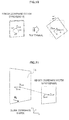
- FIGS. 14A and 14B are explanatory diagrams for describing a first scenario on the operation of the virtual object.
- FIG. 14A an image in which a real object 12d existing in the real space is shown is displayed on the screen of the terminal device 100.
- the real object 12d is an information board installed at a station.
- the data acquisition unit 170 of the terminal device 100 acquires the object data of a virtual object 16d that is associated with the real object 12d.
- the virtual object 16d is a substantially planar object displaying the map of the station, the exit information, the timetable, or the like, for example. In the example of FIG. 14A , only a part of the virtual object 16d is superimposed onto the real object 12d.
- the restraint region of the virtual object 16d is a region along the surface of the real object 12d, for example.
- the restraint region setting unit 140 sets the restraint region of the virtual object 16d based on the position and the attitude of the real object 12d. Then, it is assumed, for example, that the user dragged the real object 12d to the top left (see the arrow in the drawing) on the screen of the terminal device 100.
- the virtual object 16d is scrolled toward the back left. Then, the timetable part of the virtual object 16d, which was not displayed before the drag, is superimposed onto the real object 12d.
- FIGS. 15A and 15B are explanatory diagrams for describing a second scenario on the operation of the virtual object.
- an image in which a real object 12e existing in the real space is shown is displayed on the screen of the terminal device 100.
- the real object 12e is an information board showing a map.
- the data acquisition unit 170 of the terminal device 100 acquires object data of a virtual object 16e that is associated with the real object 12e.
- the virtual object 16e is a substantially planar object displaying map information, for example.
- the initial display contents of the map information may be the same as the map that is actually shown on the real object 12e.
- the restraint region of the virtual object 16e is a region along the surface of the real object 12e, for example.
- the restraint region setting unit 140 sets the restraint region of the virtual object 16e based on the position and the attitude of the real object 12e. Then, it is assumed, for example, that the user performed a pinch-out at the map portion on the screen of the terminal device 100.
- the map displayed by the virtual object 16e is enlarged. Moreover, the map is not simply enlarged on the screen, but is enlarged within the plane that is along the surface of the real object 12e according to the attitude of the real object 12e.
- the operation control unit 160 may scale the map within the restraint region in the case a pinch-in or a pinch-out is performed at the map portion, and may scale the entire image while keeping it parallel to the image plane in the case a pinch-in or a pinch-out is performed at a portion other than the map portion.
- the real object 12d and the virtual object 16d displayed on the screen of the terminal device 100 are again shown, as in the example of FIG. 14B .
- the virtual object 16d is scrolled to the front right.
- the timetable part of the virtual object 16d which was superimposed onto the real object 12d, has gone out of the screen, and the exit information part of the virtual object 16d is superimposed onto the real object 12d.
- the virtual object does not simply move up and down, and right and left within the screen according to the user input, but may be operated in such a way as if it is moving in the three-directional real space according to the attitude of the associated real object. It is thereby possible to allow the user to operate the AR virtual object without impairing the sense, felt by the user, of being in the augmented real space, that is, the sense of immersion of the user into the AR space.
- the display control unit 190 may recognize the surface onto which the virtual object is to be superimposed, according to the texture or the like of the input image. For example, a plane having a uniform texture in the input image, such as the wall of a building, the floor of a passage, or the like, may be recognized as the surface onto which the virtual object is to be superimposed.
- FIG. 17 is an explanatory diagram for describing the auxiliary object indicating the movable direction of the virtual object.
- three real objects, 12a, 12b, and 12c are displayed on the screen of the terminal device 100.
- the virtual object 16a is superimposed onto the real object 12a.
- An auxiliary object 17a (shadow gradation) indicating that the virtual object 16a can be scrolled to the front left is displayed at the left end of the virtual object 16a.
- the virtual object 16b is superimposed onto the real object 12b.
- An auxiliary object 17b (arrow) indicating that the virtual object 16b can be scrolled downward is displayed below the virtual object 16b.
- the virtual object 16c is superimposed onto the real object 12c.
- Auxiliary objects 17c triangular catches) indicating that the virtual object 16c can be enlarged along the surface of the real object 12c are superimposed onto the four corners of the virtual object 16c.
- a user can easily grasp how the virtual object can be operated.
- the virtual object 16a is the virtual object that is positioned nearest to the terminal device 100.
- An auxiliary object 18a which is a bold frame, is superimposed onto the virtual object 16a.
- the auxiliary object 18a is an object indicating a so-called focus.
- the terminal device 100 has been described in detail with reference to FIGS. 1 to 17 .
- the motion of an AR virtual object that is operated according to a user input is determined within the restraint region that is set in the real space based on the attitude of the real object that is recognized in the input image.
- the virtual object is not operated irrespective of the situation of the real world, but may be operated in such a way as if it is moving three-directionally in accordance with the attitude of the real object existing in the real world.
- natural operation and display can be realized without impairing the sense of immersion of the user into the AR space.
- the restraint region may be set along the surface of the real object that is recognized in the input image.
- the virtual object is a substantially planar object that displays specific information, and it may be moved, scaled, or scrolled along the surface of the real object. Accordingly, the user is allowed to freely view abundant information with a sense of reality, as if directly operating information that is shown on the real object in the real world.
- the process by the terminal device 100 described in the present specification may be realized by using any of software, hardware, and a combination of software and hardware.
- Programs configuring the software are stored in advance in a storage medium provided within or outside the device, for example.
- Each program is loaded into a RAM (Random Access Memory) at the time of execution, and is executed by a processor such as a CPU (Central Processing Unit), for example.
- RAM Random Access Memory
- CPU Central Processing Unit
- present technology may also be configured in accordance with the following numbered independent and dependent clauses
Abstract
Description
- The present disclosure contains subject matter related to that disclosed in Japanese Priority Patent Application
JP 2011-078075 - The present disclosure relates to a terminal device, an object control method, and a program.
- In recent years, a technology called Augmented Reality (AR) for superimposing additional information onto the real world and presenting it to users is gaining attention. Information to be presented to the users in the AR technology is also called annotation, and may be visualized by using various types or virtual objects such as texts, icons, animations, and the like.
- The AR technology may also be used in an application involving interaction with users. For example, with an application intended for provision of information, such as an advertisement or navigation, information meeting the needs of a user may be provided to the user by having the user operate an AR virtual object. As a document related to operation of an AR virtual object, there is
JP 2010-238098A - However, with the technology described in
JP 2010-238098A - Accordingly, a mechanism is preferably provided that is capable of realizing operation of an AR virtual object without impairing substantially a sense of immersion of a user into an AR space.
- Various respective aspects and features of the invention are defined in the appended claims. Combinations of features from the dependent claims may be combined with features of the independent claims as appropriate and not merely as explicitly set out in the claims.
- According to the present disclosure, operation of an AR virtual object can be realized without impairing the sense of immersion of a user into an AR space.
- Aspects of embodiments of the present invention include an apparatus comprising a memory storing instructions and a control unit. The control unit may execute the instructions to detect an object of interest within an image of real space, detect an orientation and a position of the object, and generate a modified image. The generating may comprise determining a region of the image of real space based on the detected orientation and position. The control unit may further execute the instructions to display a virtual image of the object in the region; change the virtual image based on a detected user input, the changed virtual image being maintained within the region; and display the modified image.
- Aspects of embodiments of the present invention include a method comprising detecting an object of interest within an image of real space, detecting an orientation and a position of the object, and generating a modified image. The generating may comprise determining a region of of real space based on the detected orientation and position, displaying a virtual image of the object in the region, changing the virtual image based on a detected user input, the changed virtual image being maintained within the region; and displaying the modified image.
- Aspects of embodiments of the present invention include a tangibly embodied non-transitory computer-readable medium storing instructions which, when executed by a processor, perform a method comprising detecting an object of interest within an image of real space. The method may further comprise detecting an orientation and a position of the object, generating a modified image. The generating may comprise determining a region of the image of real space based on the detected orientation and position. The method may further comprise displaying a virtual image of the object in the region, changing the virtual image based on a detected user input, the changed virtual image being maintained within the region, and displaying the modified image.
- Embodiments of the invention will now be described with reference to the accompanying drawings, throughout which like parts are referred to by like reference, and in which:
-
FIG. 1 is an explanatory diagram for describing an overview of a terminal device according to an embodiment; -
FIG. 2 is a block diagram showing an example of the hardware configuration of a terminal device according to an embodiment; -
FIG. 3 is a block diagram showing an example of the configuration of the logical function of a terminal device according to an embodiment; -
FIG. 4 is an explanatory diagram for describing an example of a result of image recognition; -
FIG. 5A is an explanatory diagram showing a first example of a restraint region set in an embodiment; -
FIG. 5B is an explanatory diagram showing a second example of a restraint region set in an embodiment; -
FIG. 5C is an explanatory diagram showing a third example of a restraint region set in an embodiment; -
FIG. 6 is an explanatory diagram for describing operation of a virtual object via a touch sensor; -
FIG. 7 is another explanatory diagram for describing operation of a virtual object via a touch sensor; -
FIG. 8 is a first explanatory diagram for describing operation of a virtual object via a motion sensor; -
FIG. 9 is a second explanatory diagram for describing operation of a virtual object via a motion sensor; -
FIG. 10 is a another explanatory diagram for describing operation of a virtual object via a motion sensor; -
FIG. 11 is another explanatory diagram for describing operation of a virtual object via a motion sensor; -
FIG. 12 is a flow chart showing an example of the flow of an object control process according to an embodiment; -
FIG. 13 is a flow chart showing an example of a detailed flow of an image acquisition process according to an embodiment; -
FIG. 14A is a first explanatory diagram for describing a first scenario on operation of a virtual object; -
FIG. 14B is another explanatory diagram for describing a first scenario on operation of a virtual object; -
FIG. 15A is a an explanatory diagram for describing a second scenario on operation of a virtual object; -
FIG. 15B is a another explanatory diagram for describing a second scenario on operation of a virtual object; -
FIG. 16A is an explanatory diagram for describing a third scenario on operation of a virtual object; -
FIG. 16B is another diagram for describing a third scenario on operation of a virtual object; and -
FIG. 17 is an explanatory diagram for describing an auxiliary object showing the movable direction of a virtual object. - Hereinafter, preferred embodiments of the present disclosure will be described in detail with reference to the appended drawings. Note that, in this specification and the appended drawings, structural elements that have substantially the same function and configuration are denoted with the same reference numerals, and repeated explanation of these structural elements is omitted.
-
FIG. 1 is an explanatory diagram for describing an overview of an embodiment of the technology disclosed in the present specification. Referring toFIG. 1 , aterminal device 100 carried by a user in areal space 1 is shown. - The
terminal device 100 is a device for providing an AR application involving an interaction with a user to the user. Theterminal device 100 may be a smartphone, a PC (Personal Computer), a PDA (Personal Digital Assistant), a game terminal, or a portable music player, for example. - The
real space 1 is an example of a space in which the AR application can be used.Real objects real space 1. Thereal object 12a is a board for announcements. Asymbol mark 13a is attached to thereal object 12a. Thereal object 12b is a bulletin board for information display. Thereal object 12c is an advertisement poster. The terminal devise 100 acquires, as an input image, an obtained by capturing such a real space 1 (e.g., a "real space image" or "image of real space"). The real space image may include, for example, a plurality of images of real space, When the real space image includes a plurality of images of real space obtained periodically, the real space image is said to be a "live image." It is to be understood that the term "real space image," as used herein, encompasses a single still image of real space, a plurality of still images real space, and a live image of real space. - Then, the
terminal device 100 may superimpose a virtual object for AR onto the input image, based on the recognition result of a real object shown in the input image. Information to be presented to a user via the virtual object may be any information, such as navigation information, advertisement information, shop information, news, weather reports, railway information, and the like. A user may operate a virtual object displayed on the screen of theterminal device 100, and interactively uses the AR application. - Although not explicitly shown in
FIG. 1 , a data server having a database regarding the virtual object or information to be presented to a user via the virtual object may be provided in thereal space 1. Theterminal device 100 may communicate with the data server by wireless connection, for example, and may download from the data server the latest data associated with the position of theterminal device 100. It is to be understood that any of the operations described herein (e.g., image processing, etc.) may be performed locally on a user device (e.g., terminal device 100) and/or may be performed remotely, such as by a server that is remote to the user device (e.g., a "remote server"). -
FIG. 2 is a block diagram showing an example of the hardware configuration of theterminal device 100 according to the present embodiment. Referring toFIG. 2 , theterminal device 100 includes animaging unit 102, asensor unit 104, aninput unit 106, astorage unit 108, adisplay unit 112, acommunication unit 114, abus 118, and acontrol unit 120. - The
imaging unit 102 is a camera module which may capture an image. Theimaging unit 102 captures the real space by using an image sensor such as a CCD (Charge Coupled Device) or a CMOS (Complementary Metal Oxide Semiconductor), and generates a captured image. Theimaging unit 102 may also include both or one of an imaging circuit for video input and an imaging circuit for still image input. - The
sensor unit 104 may include a group of sensors for supporting recognition of the position and the attitude of theterminal device 100, and detecting a part of user inputs to theterminal device 100. For example, thesensor unit 104 may include a GPS sensor that receives a GPS (Global Positioning System) signal and measures the latitude, the longitude and the altitude of theterminal device 100. Also, thesensor unit 104 may include a positioning sensor that measures the position of theterminal device 100 based on the intensity of a radio signal received from a wireless access point. Furthermore, thesensor unit 104 may include a motion sensor, such as an acceleration sensor that measures the three-axis acceleration of theterminal device 100 or a gyro sensor that measures the tilt angle. Input Unit - The
input unit 106 may include an input device used by a user to operate theterminal device 100 or to input information to the terminal devise 100. Typically, theinput unit 100 includes a touch sensor that detects a touch of a user on the screen of thedisplay unit 112. Alternatively (or in addition thereto), theinput unit 106 may include a pointing device such as a mouse or a touchpad, a gesture recognition module that recognize the gesture or a user shown in the image, or a line-of-sight detection module that detects the direction of the line of sight of a user wearing a head-mounted display (HMD). Furthermore, theinput unit 106 may include other types of input devices such as a keyboard, a key pad, a button, a switch, and the like. - The
storage unit 108 may be configured from a storage medium such as a semiconductor memory, a hard disk, or the like, and stores program and data to be used for processing by theterminal device 100. The data to be stored in thestorage unit 108 may include, for example, image data generated by theimaging unit 102 and sensor data generated by thesensor unit 104. The data to be stored in thestorage unit 108 may also include, for example, feature quantity data used at the time of image recognition by theterminal device 100, object data defining a virtual object, and the like. - The
display unit 112 may include a display module that is configured from an LCD (Liquid Crystal Display), an OLED (Organic Light-Emitting Diode), a CRT (Cathode Ray Tube), or the like. Thedisplay unit 112 may display on a screen an image captured by theimaging unit 102 or an image of the AR application realized by thecontrol unit 120, for example. Thedisplay unit 112 may be the screen of theterminal device 100 held by a user, or a see-through or non-see-through HMD worn by the user. - The
communication unit 114 may include a communication interface that intermediates communication by theterminal device 100 with another device (for example, the data server described above). Thecommunication unit 114 may support an arbitrary wireless communication protocol or wired communication protocol, and establishes a communication connection to another device. - The
bus 118 may connect with each other theimaging unit 102, thesensor unit 104, theinput unit 106, thestorage unit 108, thedisplay unit 112, thecommunication unit 114, and thecontrol unit 120. - The
control unit 120 may include a processor such as a CPU (Central Processing Unit), a DSP (Digital Signal Processor), or the like. Thecontrol unit 120 executes a program stored in theunit 108 or in another storage medium, and caused various functions of theterminal device 100 described later to operate. -
FIG. 3 is a block diagram showing an example of the configuration of the logical function realizes by thestorage unit 108 and thecontrol unit 120 of theterminal device 100 shown inFIG. 2 . Referring toFIG.3 , theterminal device 100 may include animage acquisition unit 110, aframe memory 112, animage recognition unit 130, a feature quantity database (DB) 132, a restraintregion setting unit 140, adetection unit 150, anoperation control unit 160, adata acquisition unit 170, anobject DB 172, and a display control unit 190. - The
image acquisition unit 110 may acquire an image showing the real space as an input image. In the present embodiment, theimage acquisition unit 110 supports two input modes, a real-time mode and a snapshot mode. In the real-time mode, theimage acquisition unit 110 sequentially acquires as input images the latest frames of the video input from theimaging unit 102. In the snapshot mode, theimage acquisition unit 110 first causes, at the time of beginning of the snapshot mode, theframe memory 112 to store a snapshot captured by theimaging unit 102. In the case theimaging unit 102 includes the imaging circuit for video input and the imaging circuit for still image input, the snapshot may be an image captured by the imaging circuit for still image input. Then, theimage acquisition unit 110 successively acquires snapshots stored in theframe memory 112 as input images. Switching between the real-time mode and the snapshot mode may be performed by a specific user input via theinput unit 106. Theimage acquisition unit 110 outputs the input image acquired in this manner to theimage recognition unit 130. - The
image recognition unit 130 may recognize which real object is shown in the input image input from theimage acquisition unit 110. Theimage recognition unit 130 also recognizes the position and the attitude, in the real space, of the real object shown in the input image. More particularly, theimage recognition unit 130 may extract a feature quantity of the input image, for example. Then, theimage recognition unit 130 checks the extracted feature quantity against the feature quantities of various known real object images that are stored in thefeature quantity DB 132 in advance, and thereby identifies the real object shown in the input image and recognizes the position and the attitude of the real object. A feature quantity extraction algorithm used by theimage recognition unit 130 may be, for example, Random Ferns method described in "Fast Keypoint Recognition using Random Ferns" (Mustafa Oezuysal, IEEE Transactions on Pattern Analysis and Machine Intelligence, Vol.32, Nr.3, pp.448-461, March 2010), or SURF method described in "SURF: Speeded Up Robust Features" (H. Bay, A. Ess, T. Tuytelaars and L. V. Gool, Computer Vision and Image Understanding (CVIU), Vol. 110, No.3, pp.346--359, 2008). Alternatively, theimage recognition unit 130 may identify the real object shown in the input image by using a known diagram or symbol (for example, a mark that is uniformly attached to a board for announcements, such as thesymbol mark 13a of thereal object 12a shown inFIG. 1 ), an artificial mark (for example, a bar code or a QR code), a natural mark or the like attached to the real object, and may recognize, based on the size and shape of the real object in the input image, its position and attitude. -
FIG. 4 is an explanatory diagram for describing an example of the result of image recognition by theimage recognition unit 130. Referring toFIG. 4 , an input image Im1, which is an example, to be input to theimage recognition unit 130 is shown. The position Xa and the attitude Wa of thereal object 12a, the position Xb and the attitude Wb of thereal object 12b, the position Xc and the attitude We of thereal object 12c shown in the input image Im1 are recognized as a result of image recognition by theimage recognition unit 130. The position X of each real object may be given as the position of the reference point of each real object by a three-dimensional global coordinate system (x, y, z). The global coordinate system may be a coordinate system indicating relative positional coordinates having the position of theterminal device 100 as the origin. Alternatively, the global coordinate system may be a coordinate system that is fixedly defined in the real space. The attitude W of each real object may be given as a rotation matrix or a quaternion indicating the rotation of each real object relative to the global coordinate system. Additionally, in the present specification, the position X and the attitude W of each real object will be described as independent variables, for the sake of simplicity of explanation. However, the position X and the attitude W of each real object may also be integrally expressed by one homogeneous transformation matrix with four rows and four columns indicating transformation between the global coordinate system and the model coordinate system of each real object. In this case, the position X and the attitude W of each real object may be extracted as necessary from the one homogeneous transformation matrix and be used. Theimage recognition unit 130 outputs an identifier, the position, and the attitude of each real object shown in the input image, which has been recognized in the above manner, to the restraintregion setting unit 140, thedata acquisition unit 170, and the display control unit 190. - The restraint
region setting unit 140 sets, in the real space shown in the input image, a restraint region that restrains the motion of a virtual object which is operated according to a user input, based on the attitude of the real object recognized by theimage recognition unit 130. The restraint region is a region having at most two dimensions that is expressed by lines or a plane. Typically, the restraintregion setting unit 140 may set the restraint region for each real object that is associated with an operable virtual object. The restraint region may be set along the surface of a real object that is recognized within the input image, for example. In this case, if the virtual object may be a substantially planar object, the virtual object is arranged on the surface of an associated real object and may be moved, scaled, or scrolled along the surface. The restraint region may also be set at a position having a predetermined offset to the real object recognized within the input image, for example. Additionally, the substantially planar object is not limited to having a completely planar surface, and may include a planar object having some bumps, irregular thickness, or the like. -
FIG. 5A is an explanatory diagram showing a first example of the restraint region set in thereal space 1 by the restraintregion setting unit 140 in the present embodiment. Referring toFIG. 5A , arestraint region 14a, which is an example, that is set in association with thereal object 12a is shown. Therestraint region 14a is a planar region set along the surface of thereal object 12a. The motion of a virtual object that is with thereal object 12a is restrained by such restraint region14a (for example, it does not move out of therestraint region 14a). -
FIG. 5B is an explanatory diagram showing a second example of the restraint region set in thereal space 1 by the restraintregion setting unit 140 in the present embodiment. Referring toFIG. 5B , arestraint region 14b, which is an example, that is set in association with thereal object 12b is shown. Therestraint region 14b is a linear region that runs through the middle of thereal object 12b and that is set along the vertical direction of thereal object 12b. The motion of a virtual object that is associated with thereal object 12b is restrained buysuch restraint region 14b (for example, it can only be scrolled in the vertical direction along therestraint region 14b). -
FIG. 5C is an explanatory diagram showing a third example of the restraint region set in thereal space 1 by the restraintregion setting unit 140 in the present embodiment. Referring toFIG. 5C , arestraint region 14c, which is an example, that is set in association with thereal object 12c is shown. Therestraint region 14c is a curved region set along the surface of thereal object 12c. As described, the shape of the restraint region is not limited to planar or straight, and may be a curved surface, a polygonal shape, a curved line shape, a zigzag line shape, or the like. - The
detection unit 150 detects a user input, and outputs user input information to theoperation control unit 160. The user input to be detected by thedetection unit 150 may include, for example, various touch inputs to the touch sensor of theinput unit 106 shown inFIG. 2 (for example, a touch, a tap, a double-tap, a drag, a flick, a pinch in, a pinch out, and the like). Furthermore, the user input to be detected by thedetection unit 150 may also include the motion of the terminal device 100 (for example, tilting, swinging, or the like) measured by the sensor group of thesensor unit 104 shown inFIG. 2 , for example. - The
operation control unit 160 may control operation of a user on the virtual object displayed on the screen of theterminal device 100. More particularly, when a user input is detected by thedetection unit 150, theoperation control unit 160 first identifies the virtual object that is the operation target. Next, theoperation control unit 160 determines, according to the user input, the motion of the identified virtual object within the restraint region that is associated with the real object corresponding to the virtual object. Then, theoperation control unit 160 notifies the display control unit 190 of the motion of the virtual object which has been determined, and causes the arranged location, the size, the scroll position or the like of the virtual object on the screen to be changed by the display control unit 190. The motion of the virtual object, such as movement, scaling, scrolling or the like, is thereby visualized. -
FIGS. 6 and 7 are explanatory diagrams for describing operation, controlled by theoperation control unit 160, of the virtual object via the touch sensor. Referring toFIG. 6 , aplanar restraint region 14 set in the real space and animage plane 103 of an imaging device are shown. The position X0 and the attitude W0 of therestraint region 14 may be the same as the position and the attitude of the real object that is associated with therestraint region 14, or may have a predetermined offset to the position and the attitude of the real object. An input position Cin of a user input to the touch sensor is given by a camera coordinate system (u, v, 1) on theimage plane 103. Theoperation control unit 160 may calculate a position Xin within therestraint region 14 corresponding to the input position Cin, according to the following pinhole mode, for example.
- In Formula (1), C0 is a position on the image plane corresponding to the reference position X0 of the
restraint region 14, matrix A is a camera internal parameter, and A is a parameter for normalization. The camera internal parameter A is given in advance, as by the following formula, according to the property of theimaging unit 102.
- Here, f is the focal length, θ is the orthogonality of an image axis (ideal value is 90 degrees), ku is the scale of the vertical axis of the image plane (rate of change of scale from the coordinate system of the real space to the camera coordinate system), kv is the scale of the horizontal axis of the image plane, and (uo,vo) is the centre position of the image plane.
- For example, for a user input specifying a vector such as a drag, the
operation control unit 160 may determine a motion vector Vin of the virtual object within therestraint region 14, as by the following formula, based on two input positions, Cin1 and Cin2, corresponding to the start point and end point of the vector.
- In Formula (3), Xin1 and Xin2 are positions in the restraint region corresponding to the input positions Cin1, and Cin2, respectively. Additionally, even if the restraint region has a shape of a curved surface or a polygonal shape, the
operation control unit 160 may likewise determine the position in the restraint region corresponding to each input position, by projecting the input positions of the user input on the restraint region. Also, if the restraint region is linearly shaped, theoperation control unit 160 may project the input position of the user input on this one-dimensional restraint region. - At the time of determining the motion vector Vin by projecting the input positions of the user input on the restraint region as by the above Formula (3), if the distance between the
restraint region 14 and the terminal devise 100 is large, the magnitude of the motion vector Vin may become excessively large relative to the user input. Thus, theoperation control unit 160 may change the proportion of the magnitude of the motion vector Vin to the magnitude of the input vector on the screen, according to the distance between theterminal device 100 and therestraint region 14. This enables the user to make subtle adjustments on the motion of the virtual object with more ease. The magnitude of the input vector and the magnitude of the motion vector Vin correspond, for example, to the amount of dragging on the screen and the amount of motion of the virtual object, respectively. - For example, in the case a drag from the input position Cin1 to Cin2 is detected in the example of
FIG. 7 , theoperation control unit 150 calculates the positions Xin1 and Xin2 within therestraint region 14 corresponding respectively to the input positions Cin1 and Cin2. Here, a distance D between theterminal device 100 and therestraint region 14 exceeds a predetermined threshold The. Accordingly, theoperation control unit 160 calculates a corrected motion vector V'in of the virtual object by multiplying the motion vector Vin from the position Xin1 to Xin2 by a coefficient k (k < 1). The coefficient k may be a coefficient that decreases as the distance between theterminal device 100 and therestraint region 14 increases, for example. -
FIGS. 8 to 11 are explanatory diagrams for describing operation, controlled by theoperation control unit 160, of the virtual object via the motion sensor. - Referring to
FIG. 8 , a sensor coordinate system (a1, a2, a3) of the acceleration sensor of theterminal device 100 is shown. For example, the a1 axis is an axis along the horizontal direction of the screen of theterminal device 100, the a2 axis is an axis along the vertical direction of the screen, and the a3 axis is an axis along the depth direction of the screen. Here, it is assumed, for example, that the user swings theterminal device 100 to the left along the horizontal direction of the screen of theterminal device 100 while touching the input position Cin3. Then, an acceleration vector Ain3 having a large value for the a1 axis component occurs in sensor data from the acceleration sensor. When such sensor data is input from thedetection unit 150, theoperation control unit 160 calculates a motion vector within the restraint region corresponding to the acceleration vector Ain3. In the example ofFIG. 9 , a case is shown where a motion vector Vin3 corresponding to the acceleration vector Ain3 is calculated by projecting the acceleration vector Ain3 on the plane of therestraint region 14. - Referring to
FIG. 10 , a sensor coordinate system (w1, w2, w3) for a tilt angle measured by the gyro of theterminal device 100 is shown. Here, it is assumed, for example, that the user tilts theterminal device 100 around an axis vertical to the screen of the terminal devise 100 (in the w1 direction) while touching the input position Cin4. Then, the value of the w1 axis component increases in the sensor data from the gyro sensor. When such sensor data is input from thedetection unit 150, theoperation control unit 160 perceives that a horizontal component Gin4 of gravity G is added to theterminal device 100. Then, theoperation control unit 160 calculates a motion vector within the restraint region corresponding to the horizontal component Gin4 of gravity G. In the example ofFIG. 11 , a case is shown where a motion vector Vin4 corresponding to the horizontal component Gin4 is calculated by projecting the horizontal component Gin4 on the plane of therestraint region 14. - Additionally, a user input via the touch sensor or the motion sensor has been mainly described here. However, the
operation control unit 160 may also control operation of the virtual object according to a user input of a type different from the above examples, such as a predetermined gesture of the user, for example. The gesture of the user may be recognized from the image captured by an imaging device (different from the device capturing the input image) that is pointed toward the user. Alternatively, the gesture of the user may be recognized from the image captured by an imaging device pointed toward the direction of the line of sight of the user, as in the case of using the HMD, for example. - The
operation control unit 160 may determine the virtual object to be the operation target according to the input position of a user input. For example, in the case the virtual object to be the operation target is to be selected by the start of dragging or touch on the touch sensor, a virtual object whose determination region exists on the projection line connecting the input position and the focus position of the camera is determined to be the operation target. In the present specification, the determination region refers to a region on the screen that is associated with a virtual object that causes, by being specified by the user, the virtual object to be determined as the target object. In the case there are determination regions of a plurality of virtual objects on the projection line, the virtual object that is positioned nearest to theterminal device 100 may be made the operation target. The determination region of the virtual object does not necessarily have to coincide with the region in which the virtual object is displayed. Also, theoperation control unit 160 may also specify, regardless of the determination region, the largest displayed virtual object on the screen of the terminal 100, the virtual object positioned nearest to theterminal device 100, a virtual object that is aligned in parallel with the screen of theterminal device 100, or the like, as the operation target. - In the present embodiment, the motion of the virtual object may be determined according to the type of the user input, and the position or the motion vector within the restraint region determined according to the user input.
- For example, it is assumed that the virtual object is a substantially planar object that displays specific information. The specific information may be navigation information, advertisement information, shop information, news, weather reports, railway information, or the like, for example. In this case, if the substantival planar virtual object is dragged by the user, for example, the
operation control unit 160 may scroll the displayed information within a three-dimensional space, along the direction of the motion vector within the restraint region determined according to the drag direction. The amount of scroll may, for example, correspond to the magnitude of the motion vector. Also, if the substantially planar virtual object is pinched in or pinched out by the user, theoperation control unit 160 may scale (e.g. reduce or enlarge) the displayed information according to the magnitude of the motion vector within the restraint region corresponding to the pinch-in or pinch-out. Furthermore, if any of positions on the screen is tapped in a state where the substantially planar virtual object is already specified, theoperation control unit 160 may move the virtual object to the position within the restraint region corresponding to the tapped position. Also, if an acceleration is added to theterminal device 100 in a state where the substantially planar virtual object is already specified, theoperation control unit 160 may scroll the displayed information within a three-dimensional space along the direction of the motion vector within the restraint region corresponding to the acceleration vector that has occurred. Examples of such motion of the virtual object will be further described later with reference to the drawings. - Additionally, the virtual object is not restricted to the above examples, and it may be a three-dimensional object (an announcement board for navigation, a polygon of merchandise being advertised, or the like), for example. Also in this case, the location, the size or the like of the virtual object may be determined according to the type of the user input, and the position or the motion vector within the restraint region determined according to the user input.
- The
data acquisition unit 170 may acquire data regarding the virtual object that is superimposed onto the input image by the display control unit 190. The data to be acquired by thedata acquisition unit 170 includes object data defining the virtual object. The object data may define, for example, the type of the virtual object, the identifier of the associated real object, the relative display position from the real object, the contents of information presented to the user, and the like. The contents of information presented to the user may be in a text format or an image format. Thedata acquisition unit 170 may also acquire object data that is stored in advance in theobject DB 172. Alternatively, thedata acquisition unit 170 may acquire the latest object data from a data server installed in the real space via thecommunication unit 114. The object data to be provided by the data server may be data different depending on the position of theterminal device 100 measured by thesensor unit 104, for example. Thedata acquisition unit 170 outputs the object data as described above to the display control unit 190. - The display control unit 190 generates an output image by superimposing the virtual object onto the input image. More particularly, the object data of the virtual object that is associated with a real object that is recognized as being shown in the input image by the
image recognition unit 130 is input to the display control unit 190 from thedata acquisition unit 170, for example. The display control unit 190 generates an object image of the virtual object based on the object data as described. The object image generated by the display control unit 190 is typically an image obtained by projecting a virtual object that is virtually arranged in a three-dimensional real space on the image plane of the terminal device 100 (according to the pinhole method described above, for example). The position and the attitude of the virtual object within the real space may be determined according to the position and the attitude of the associated real object and the definition by the object data. Then, the display control unit 190 displays the image of the AR application by outputting the generated output image to thedisplay unit 112. - Furthermore, the display control unit 190 changes the state of the virtual object (the position, the attitude, the size, the scroll position, or the like) according to the motion of the virtual object determined by the
operation control unit 160. For example, in the real-time mode, the display control unit 190 superimposes the object image of the virtual object whose state changes moment by moment according to the user input onto each of the input images sequentially acquired by theimage acquisition unit 110. The motion of the virtual object can thereby be expressed in the output image that is updated in real time. Also, in the snapshot mode, the display control unit 190 replicates the snapshot of the input image acquired from theframe memory 112 by theimage acquisition unit 110 for a plurality of frames, and superimposes the object image expressing the motion of the virtual object on each of the replicated snapshots. The motion of the virtual object is thereby expressed on the snapshot of a still image. - Also, the display control unit 190 may further superimpose onto the input image an auxiliary object indicating the movable direction of the virtual object within the restraint region. Furthermore, the display control unit 190 may further superimpose onto the input image an auxiliary object indicating the determination region of each virtual object. An example of the auxiliary object to be displayed by the display control unit 190 will be described later with reference to a drawing.
-
FIG. 12 is a flow chart showing an example of the flow of an object control process by theterminal device 100 according to the present embodiment. - Referring to
FIG. 12 , first, theimage acquisition unit 110 acquires an input image that has been captured by theimaging unit 102 or that is stored in the frame memory 112 (step S102). Next, theimage recognition unit 130 may recognize the real object(s) shown in the acquired input image, and the position and the attitude of the real object(s) (step S104). Next, thedata acquisition unit 170 acquires object data regarding the recognized real object(s) from theobject DB 172 or an external data server (step S106). - Next, the
operation control unit 100 determines whether a user input for operating a virtual object has been detected by thedetection unit 150 or not (step S103). Here, in the case a user input has been detected by thedetection unit 150, the process proceeds to step S110. On the other hand, in the case a user input has not been detected, the process proceeds to step S118. - In the case a user input has been detected, the
operation control unit 160 identifies the virtual object that is the operation target, based on a reference such as the input position of the user input, the size of the virtual object on the screen, the distance between the virtual object and theterminal device 100, or the like (step S110). Next, theoperation control unit 160 recognizes a restraint region set by the restraintregion setting unit 140 in association with the virtual object which has been identified (step S112). Next, theoperation control unit 160 calculates the three-dimensional position or the vector within the restraint region corresponding to the input position or the input vector of the user input (step S114). Then, theoperation control unit 160 determines the motion of the virtual object that is the operation target, based on the position or the vector within the restraint region which has been calculated and the type of the user input (step S116). - In step S118, the display control unit 190 generates object image(s) of the virtual object(s) by projecting the virtual object(s) which are virtually arranged within the real space onto the image plane, and superimposes the generated object image(s) onto the input image (step S118). The state of the virtual object here is, in the case the virtual object is not operated, an initial state (the initial state may be defined by the object data). On the other hand, in the case the virtual object is operated, the state of the virtual object is the state that has been changed according to the motion determined by the
operation control unit 160. Next, the display control unit 190 further superimposes onto the input image an auxiliary object that indicates the movable direction of each virtual object within the restraint region (step S120). Then, an output image onto which the virtual object(s) and the auxiliary object(s) have been superimposed is displayed on the screen (step S122). - In the real-time mode, the object control process shown in
FIG. 12 may be repeated for each frame captured by theimaging unit 102. Also, in the snapshot mode, the object control process may be performed using a snapshot acquired from theframe memory 112 by theimage acquisition unit 110 as the input image. In the snapshot mode, the motion of the virtual object may be expressed as an animation by repeatedly performing the process through steps S118 to S122 for one (or one-stroke) user input. -
FIG. 13 is a flow chart showing an example of a detailed flow of the image acquisition process at step S5102 ofFIG. 12 . - Referring to
FIG. 13 , theimage acquisition unit 110 first determines whether the current mode is the snapshot mode or the real-time mode (step S132). If the current mode here is the real-time mode, theimage acquisition unit 110 acquires the latest input image from the imaging unit 102 (step S134). On the other hand, if the current mode is the snapshot mode, theimage acquisition unit 110 determines whether or not to newly acquire a snapshot (step S136). For example, in the case the snapshot mode is newly started or refresh of the snapshot is instructed by the user, theimage acquisition unit 110 determines that the snapshot is to be newly acquired. If it is determined here that the snapshot is to be newly acquired, theimage acquisition unit 110 acquires the latest input image from the imaging unit 102 (step S138), and causes theframe memory 112 to store the acquired input image as the snapshot (step S140). On the other hand, if it is determined that the snapshot does not have to be newly acquired, theimage acquisition unit 110 acquires the snapshot stored in theframe memory 112 as the input image (step S142). - Next, three illustrative scenarios on the operation of the virtual object that may be realized using the
terminal device 100 described above will be described. -
FIGS. 14A and14B are explanatory diagrams for describing a first scenario on the operation of the virtual object. - Referring to
FIG. 14A , an image in which areal object 12d existing in the real space is shown is displayed on the screen of theterminal device 100. Thereal object 12d is an information board installed at a station. When it is recognized by theimage recognition unit 130 that thereal object 12d is shown in the input image, thedata acquisition unit 170 of theterminal device 100 acquires the object data of avirtual object 16d that is associated with thereal object 12d. Thevirtual object 16d is a substantially planar object displaying the map of the station, the exit information, the timetable, or the like, for example. In the example ofFIG. 14A , only a part of thevirtual object 16d is superimposed onto thereal object 12d. The restraint region of thevirtual object 16d is a region along the surface of thereal object 12d, for example. The restraintregion setting unit 140 sets the restraint region of thevirtual object 16d based on the position and the attitude of thereal object 12d. Then, it is assumed, for example, that the user dragged thereal object 12d to the top left (see the arrow in the drawing) on the screen of theterminal device 100. - Referring to
FIG. 14B , as a result of the above drag, thevirtual object 16d is scrolled toward the back left. Then, the timetable part of thevirtual object 16d, which was not displayed before the drag, is superimposed onto thereal object 12d. -
FIGS. 15A and15B are explanatory diagrams for describing a second scenario on the operation of the virtual object. - Referring to
FIG. 15A , an image in which areal object 12e existing in the real space is shown is displayed on the screen of theterminal device 100. Thereal object 12e is an information board showing a map. When it is recognized by theimage recognition unit 130 that thereal object 12e is shown in the input image, thedata acquisition unit 170 of theterminal device 100 acquires object data of avirtual object 16e that is associated with thereal object 12e. Thevirtual object 16e is a substantially planar object displaying map information, for example. The initial display contents of the map information may be the same as the map that is actually shown on thereal object 12e. The restraint region of thevirtual object 16e is a region along the surface of thereal object 12e, for example. The restraintregion setting unit 140 sets the restraint region of thevirtual object 16e based on the position and the attitude of thereal object 12e. Then, it is assumed, for example, that the user performed a pinch-out at the map portion on the screen of theterminal device 100. - Referring to
FIG. 15B , as a result of the above pinch-out, the map displayed by thevirtual object 16e is enlarged. Moreover, the map is not simply enlarged on the screen, but is enlarged within the plane that is along the surface of thereal object 12e according to the attitude of thereal object 12e. - Additionally, for example, the
operation control unit 160 may scale the map within the restraint region in the case a pinch-in or a pinch-out is performed at the map portion, and may scale the entire image while keeping it parallel to the image plane in the case a pinch-in or a pinch-out is performed at a portion other than the map portion. - Referring to
FIG. 16A , thereal object 12d and thevirtual object 16d displayed on the screen of theterminal device 100 are again shown, as in the example ofFIG. 14B . Here, it is assumed, for example, that the user tilted the main body of theterminal device 100 to the right. - Referring to
FIG. 16B , as a result of theterminal device 100 being tilted, thevirtual object 16d is scrolled to the front right. In the example ofFIG. 16B , the timetable part of thevirtual object 16d, which was superimposed onto thereal object 12d, has gone out of the screen, and the exit information part of thevirtual object 16d is superimposed onto thereal object 12d. - As in the examples of these scenarios, according to the present embodiment, the virtual object does not simply move up and down, and right and left within the screen according to the user input, but may be operated in such a way as if it is moving in the three-directional real space according to the attitude of the associated real object. It is thereby possible to allow the user to operate the AR virtual object without impairing the sense, felt by the user, of being in the augmented real space, that is, the sense of immersion of the user into the AR space.
- Additionally, an example where the virtual object is superimposed onto the surface of the real object shown in the input image is mainly described, but the virtual object may be superimposed onto a position separate from the surface of the real object. Also, the display control unit 190 may recognize the surface onto which the virtual object is to be superimposed, according to the texture or the like of the input image. For example, a plane having a uniform texture in the input image, such as the wall of a building, the floor of a passage, or the like, may be recognized as the surface onto which the virtual object is to be superimposed.
-
FIG. 17 is an explanatory diagram for describing the auxiliary object indicating the movable direction of the virtual object. - Referring to
FIG. 17 , three real objects, 12a, 12b, and 12c, are displayed on the screen of theterminal device 100. Thevirtual object 16a is superimposed onto thereal object 12a. Anauxiliary object 17a (shadow gradation) indicating that thevirtual object 16a can be scrolled to the front left is displayed at the left end of thevirtual object 16a. Also, thevirtual object 16b is superimposed onto thereal object 12b. Anauxiliary object 17b (arrow) indicating that thevirtual object 16b can be scrolled downward is displayed below thevirtual object 16b. Thevirtual object 16c is superimposed onto thereal object 12c.Auxiliary objects 17c (triangular catches) indicating that thevirtual object 16c can be enlarged along the surface of thereal object 12c are superimposed onto the four corners of thevirtual object 16c. - As described, by displaying in association with the virtual object the auxiliary object indicating the movable direction of the virtual object, a user can easily grasp how the virtual object can be operated.
- Furthermore, in the example of
FIG. 17 , thevirtual object 16a is the virtual object that is positioned nearest to theterminal device 100. Anauxiliary object 18a, which is a bold frame, is superimposed onto thevirtual object 16a. Theauxiliary object 18a is an object indicating a so-called focus. When a certain user input is performed without any of the virtual objects being specified by the user, a focused virtual object may be specified as the operation target by theoperation control unit 160. - In the foregoing, the
terminal device 100 according to an embodiment has been described in detail with reference toFIGS. 1 to 17 . According to this embodiment, the motion of an AR virtual object that is operated according to a user input is determined within the restraint region that is set in the real space based on the attitude of the real object that is recognized in the input image. Accordingly, the virtual object is not operated irrespective of the situation of the real world, but may be operated in such a way as if it is moving three-directionally in accordance with the attitude of the real object existing in the real world. Thus, at the time of operation on the virtual object, natural operation and display can be realized without impairing the sense of immersion of the user into the AR space. - Furthermore, according to the present embodiment, the restraint region may be set along the surface of the real object that is recognized in the input image. Also, the virtual object is a substantially planar object that displays specific information, and it may be moved, scaled, or scrolled along the surface of the real object. Accordingly, the user is allowed to freely view abundant information with a sense of reality, as if directly operating information that is shown on the real object in the real world.
- Furthermore, the process by the
terminal device 100 described in the present specification may be realized by using any of software, hardware, and a combination of software and hardware. Programs configuring the software are stored in advance in a storage medium provided within or outside the device, for example. Each program is loaded into a RAM (Random Access Memory) at the time of execution, and is executed by a processor such as a CPU (Central Processing Unit), for example. - It should be understood by those skilled in the art that various modifications, combinations, sub-combinations and alterations may occur depending on design requirements and other factors insofar as they are within the scope of the appended claims or the equivalents thereof.
- In so far as embodiments of the invention described above are implemented, at least in part, using software-controlled data processing apparatus, it will be appreciated that a computer program providing such software control and a transmission, storage or other medium by which such a computer program is provided are envisaged as aspects of the present invention.
- Additionally, embodiments of the present invention the present technology may also be configured in accordance with the following numbered independent and dependent clauses
- Clause (1) A terminal device including:
- an image acquisition unit for acquiring an input image showing a real space;
- a display control unit for superimposing a virtual object onto the input image and displaying the virtual object;
- a detection unit for detecting a user input; and
- an operation control unit for determining a motion of the virtual object which is operated according to the user input, within a region having at most two dimensions that is set within the real space based on an attitude of a real object recognized within the input image.
- Clause (2) The terminal device according to clause (1),
wherein the region is set along a surface of the real object recognized within the input image. - Clause (3) The terminal device according to clause (2),
wherein the virtual object is a substantially planar object displaying specific information, and
wherein the motion of the virtual object is movement, scaling, or scrolling of the virtual object. - Clause (4) The terminal device according to clause (2) or (3),
wherein the detection unit detects a user input to a screen displaying the virtual object, and
wherein the operation control unit calculates a position, within the region, corresponding to an input position on the screen, and determines the motion of the virtual object based on the calculated position. - Clause (5) The terminal device according to clause (4),
wherein the detection unit detects a drag on the screen as the user input, and
wherein the operation control unit changes, according to a distance between the terminal device and the region, a proportion of an amount of the motion of the virtual object to an amount of dragging on the screen. - Clause (6) The terminal device according to clause (2) or (3),
wherein the detection unit detects, using a sensor, a motion of the terminal device as the user input, and
wherein the operation control unit calculates a second vector, within the region, corresponding to a first vector indicating the motion of the terminal device, and determines the motion of the virtual object based on the calculated second vector. - Clause (7) The terminal device according to any of clauses (1) to (6),
wherein the display control unit further superimposes onto the input image an auxiliary object indicating a movable direction of the virtual object within the region. - Clause (8) The terminal device according to any of clauses (1) to (7),
wherein the image acquisition unit acquires a snapshot captured by an imaging device as the input image, in a case a predetermined user input is detected, and
wherein the display control unit expresses, on the snapshot, the motion of the virtual object. - Clause (9) An object control method performed by a terminal device that acquires an input image showing a real space and that superimposes a virtual object onto the input image and displays the virtual object, including:
- detecting a user input; and
- determining a motion of the virtual object which is operated according to the user input, within a region having at most two dimensions that is set within the real space based on an attitude of a real object recognized within the input image.
- Clause (10) A program for causing a computer for controlling a terminal device that acquires an input image showing a real space and that superimposes a virtual object onto the input image and displays the virtual object to function as:
- a detection unit for detecting a user input; and
- an operation control unit for determining a motion of the virtual object which is operated according to the user input, within a region having at most two dimensions that is set within the real space based on an attitude of a real object recognized within the input image.
Claims (15)
- An apparatus comprising:a memory storing instructions; anda control unit executing the instructions to:detect an object of interest within an image of real space;detect an orientation and a position of the object;generate a modified image, the generating comprising:determining a region of the image of real space based on the detected orientation and position;display a virtual image of the object in the region;change the virtual image based on a detected user input, the changed virtual image being maintained within the region; anddisplay the modified image.
- The apparatus of claim 1, wherein determining a region of the image of real space further comprises:requesting that a remote server determine the region of the image of real space; andreceiving an indication of a determined region from the remote server.
- The apparatus of claim 1, wherein detecting an object of interest further comprises:requesting that a remote server detect the object of interest; andreceiving an indication of a detected object of interest from the remote server.
- The apparatus of claim 1, wherein detecting an orientation and a position of the object further comprises:requesting that a remote server detect an orientation and a position of the object; andreceiving an indication of a detected orientation and a position of the object from the remote server.
- The apparatus of claim 1, wherein changing the virtual image based on a detected user input further comprises:detecting the user input;requesting that a remote server change the virtual image based on the detected user input; andreceiving an indication of a changed the virtual image from the remote server.
- The apparatus of claim 1, wherein determining a region of the image of real space further comprises:determining a surface of the object of interest based on the detected orientation and position; andprojecting the region onto a portion of the determined surface.
- The apparatus of claim 1, wherein:the virtual image comprises a collection of information; anddisplaying the virtual image further comprises displaying pages of the information in the region, and optionally:wherein changing the virtual image based on a detected user input comprises scrolling the pages of the collection of information, and / orwherein changing the virtual image based on a detected user input comprises scaling at least one of the pages of the collection of information.
- The apparatus of claim 1, wherein:the user input specifies an input position; andchanging the virtual image further comprises projecting the input position onto the virtual image.
- The apparatus of claim 8, wherein the projected input position selects a portion of the virtual image, and optionally:wherein selecting the portion of the virtual image provides the user with additional information received from a server.
- The apparatus of claim 8, wherein the user specifies the input position via a touch panel.
- The apparatus of claim 1, wherein the instructions further comprise instructions for:determining a possible change of the virtual image based on the region; andsuperimposing onto the virtual image an indication of the possible change, and optionally:wherein the possible change comprises at least one of: re-sizing the virtual image, moving the virtual image, and changing information displayed in the virtual image.
- The apparatus of claim 1, wherein the modified image further comprises a still image of real space, and optionally:wherein the image of real space is selected from among a plurality of candidate still images of real space.
- The apparatus of claim 1, wherein the image of real space is a live image of real space.
- A method comprising:detecting an object of interest within an image of real space;detecting an orientation and a position of the object;generating a modified image, the generating comprising:determining a region of the image of real space based on the detected orientation and position;display a virtual image of the object in the region;change the virtual image based on a detected user input, the changed virtual image being maintained within the region; anddisplaying the modified image.
- A tangibly embodied non-transitory computer-readable medium storing instructions which, when executed by a processor, perform a method comprising:detecting an object of interest within an image of real space;detecting an orientation and a position of the object;generating a modified image, the generating comprising:determining a region of the image of real space based on the detected orientation and position;display a virtual image of the object in the region;change the virtual image based on a detected user input, the changed virtual image being maintained within the region; anddisplaying the modified image.
Priority Applications (1)
| Application Number | Priority Date | Filing Date | Title |
|---|---|---|---|
| EP19217816.8A EP3657447A1 (en) | 2011-03-31 | 2012-03-22 | Augmented reality apparatus, method and program |
Applications Claiming Priority (1)
| Application Number | Priority Date | Filing Date | Title |
|---|---|---|---|
| JP2011078075A JP5724543B2 (en) | 2011-03-31 | 2011-03-31 | Terminal device, object control method, and program |
Related Child Applications (2)
| Application Number | Title | Priority Date | Filing Date |
|---|---|---|---|
| EP19217816.8A Division EP3657447A1 (en) | 2011-03-31 | 2012-03-22 | Augmented reality apparatus, method and program |
| EP19217816.8A Division-Into EP3657447A1 (en) | 2011-03-31 | 2012-03-22 | Augmented reality apparatus, method and program |
Publications (3)
| Publication Number | Publication Date |
|---|---|
| EP2506222A2 true EP2506222A2 (en) | 2012-10-03 |
| EP2506222A3 EP2506222A3 (en) | 2013-09-11 |
| EP2506222B1 EP2506222B1 (en) | 2020-08-05 |
Family
ID=45999589
Family Applications (2)
| Application Number | Title | Priority Date | Filing Date |
|---|---|---|---|
| EP12160712.1A Active EP2506222B1 (en) | 2011-03-31 | 2012-03-22 | Augmented reality apparatus, method and program |
| EP19217816.8A Pending EP3657447A1 (en) | 2011-03-31 | 2012-03-22 | Augmented reality apparatus, method and program |
Family Applications After (1)
| Application Number | Title | Priority Date | Filing Date |
|---|---|---|---|
| EP19217816.8A Pending EP3657447A1 (en) | 2011-03-31 | 2012-03-22 | Augmented reality apparatus, method and program |
Country Status (4)
| Country | Link |
|---|---|
| US (1) | US8811667B2 (en) |
| EP (2) | EP2506222B1 (en) |
| JP (1) | JP5724543B2 (en) |
| CN (1) | CN102750079B (en) |
Cited By (4)
| Publication number | Priority date | Publication date | Assignee | Title |
|---|---|---|---|---|
| CN104899920A (en) * | 2015-05-25 | 2015-09-09 | 联想(北京)有限公司 | Image processing method, image processing device and electronic device |
| CN105074617A (en) * | 2013-03-11 | 2015-11-18 | 日本电气方案创新株式会社 | Three-dimensional user interface device and three-dimensional operation processing method |
| US9721391B2 (en) | 2014-05-13 | 2017-08-01 | Canon Kabushiki Kaisha | Positioning of projected augmented reality content |
| WO2018080817A1 (en) * | 2016-10-25 | 2018-05-03 | Microsoft Technology Licensing, Llc | Virtual reality and cross-device experiences |
Families Citing this family (64)
| Publication number | Priority date | Publication date | Assignee | Title |
|---|---|---|---|---|
| KR101426082B1 (en) * | 2007-10-04 | 2014-07-31 | 삼성전자주식회사 | Method for remote-controlling target apparatus using mobile communication terminal and remote control system thereof |
| US9606992B2 (en) * | 2011-09-30 | 2017-03-28 | Microsoft Technology Licensing, Llc | Personal audio/visual apparatus providing resource management |
| KR101873525B1 (en) * | 2011-12-08 | 2018-07-03 | 삼성전자 주식회사 | Device and method for displaying a contents in wireless terminal |
| US9767720B2 (en) * | 2012-06-25 | 2017-09-19 | Microsoft Technology Licensing, Llc | Object-centric mixed reality space |
| GB201216210D0 (en) | 2012-09-12 | 2012-10-24 | Appeartome Ltd | Augmented reality apparatus and method |
| JP6178066B2 (en) | 2012-11-06 | 2017-08-09 | 株式会社ソニー・インタラクティブエンタテインメント | Information processing apparatus, information processing method, program, and information storage medium |
| JPWO2014073345A1 (en) * | 2012-11-09 | 2016-09-08 | ソニー株式会社 | Information processing apparatus, information processing method, and computer-readable recording medium |
| US10715817B2 (en) * | 2012-12-19 | 2020-07-14 | Nvidia Corporation | Apparatus and method for enhancing motion estimation based on user input |
| US20140210857A1 (en) * | 2013-01-28 | 2014-07-31 | Tencent Technology (Shenzhen) Company Limited | Realization method and device for two-dimensional code augmented reality |
| JP5962547B2 (en) * | 2013-03-08 | 2016-08-03 | ソニー株式会社 | Information processing apparatus, information processing method, and program |
| JP2014191718A (en) | 2013-03-28 | 2014-10-06 | Sony Corp | Display control device, display control method, and recording medium |
| JP2014191688A (en) * | 2013-03-28 | 2014-10-06 | Sony Corp | Information processor, information processing method and storage medium |
| JP5790692B2 (en) | 2013-03-29 | 2015-10-07 | ソニー株式会社 | Information processing apparatus, information processing method, and recording medium |
| EP2983139A4 (en) | 2013-04-04 | 2016-12-28 | Sony Corp | Image processing device, image processing method and program |
| EP3920148A1 (en) | 2013-04-04 | 2021-12-08 | Sony Group Corporation | Information processing device, information processing method, and program |
| US20160049011A1 (en) | 2013-04-04 | 2016-02-18 | Sony Corporation | Display control device, display control method, and program |
| US20160055676A1 (en) | 2013-04-04 | 2016-02-25 | Sony Corporation | Display control device, display control method, and program |
| US9245387B2 (en) * | 2013-04-12 | 2016-01-26 | Microsoft Technology Licensing, Llc | Holographic snap grid |
| US10509533B2 (en) | 2013-05-14 | 2019-12-17 | Qualcomm Incorporated | Systems and methods of generating augmented reality (AR) objects |
| KR20150008733A (en) * | 2013-07-15 | 2015-01-23 | 엘지전자 주식회사 | Glass type portable device and information projecting side searching method thereof |
| JP6314394B2 (en) | 2013-09-13 | 2018-04-25 | 富士通株式会社 | Information processing apparatus, setting method, setting program, system, and management apparatus |
| US9607437B2 (en) * | 2013-10-04 | 2017-03-28 | Qualcomm Incorporated | Generating augmented reality content for unknown objects |
| JP2015095147A (en) | 2013-11-13 | 2015-05-18 | ソニー株式会社 | Display control device, display control method, and program |
| US10460022B2 (en) | 2013-11-13 | 2019-10-29 | Sony Corporation | Display control device, display control method, and program for displaying an annotation toward a user |
| JP2015095802A (en) | 2013-11-13 | 2015-05-18 | ソニー株式会社 | Display control apparatus, display control method and program |
| CN104679973A (en) * | 2013-12-03 | 2015-06-03 | 深圳市艾酷通信软件有限公司 | File system for mobile terminals and implementing method thereof |
| JP6299234B2 (en) | 2014-01-23 | 2018-03-28 | 富士通株式会社 | Display control method, information processing apparatus, and display control program |
| JP6196562B2 (en) * | 2014-02-12 | 2017-09-13 | 日本電信電話株式会社 | Subject information superimposing apparatus, subject information superimposing method, and program |
| GB201404990D0 (en) | 2014-03-20 | 2014-05-07 | Appeartome Ltd | Augmented reality apparatus and method |
| GB201410285D0 (en) | 2014-06-10 | 2014-07-23 | Appeartome Ltd | Augmented reality apparatus and method |
| KR102210633B1 (en) * | 2014-07-09 | 2021-02-02 | 엘지전자 주식회사 | Display device having scope of accredition in cooperatin with the depth of virtual object and controlling method thereof |
| JP6476657B2 (en) * | 2014-08-27 | 2019-03-06 | 株式会社リコー | Image processing apparatus, image processing method, and program |
| JP6417797B2 (en) * | 2014-09-03 | 2018-11-07 | 株式会社リコー | Information terminal device, information processing method, system, and program |
| JP6437811B2 (en) * | 2014-12-10 | 2018-12-12 | 株式会社Nttドコモ | Display device and display method |
| US20160232714A1 (en) * | 2015-02-06 | 2016-08-11 | Liberty Procurement Co. Inc. | Apparatus, method and system for providing interactive multimedia content based on print media |
| JP6346585B2 (en) * | 2015-04-06 | 2018-06-20 | 日本電信電話株式会社 | Operation support apparatus and program |
| CN107710284B (en) * | 2015-06-30 | 2021-11-23 | 奇跃公司 | Techniques for more efficiently displaying text in a virtual image generation system |
| US10758822B2 (en) * | 2015-12-24 | 2020-09-01 | Sony Interactive Entertainment Inc. | Main beam direction determination device, main beam direction determination method, and program |
| CN105681684A (en) * | 2016-03-09 | 2016-06-15 | 北京奇虎科技有限公司 | Image real-time processing method and device based on mobile terminal |
| CN105657294A (en) * | 2016-03-09 | 2016-06-08 | 北京奇虎科技有限公司 | Method and device for presenting virtual special effect on mobile terminal |
| CN105786432A (en) * | 2016-03-18 | 2016-07-20 | 北京奇虎科技有限公司 | Method and device for displaying virtual image on mobile terminal |
| CN109074212B (en) * | 2016-04-26 | 2021-12-31 | 索尼公司 | Information processing apparatus, information processing method, and program |
| CN106200916B (en) * | 2016-06-28 | 2019-07-02 | Oppo广东移动通信有限公司 | Control method, device and the terminal device of augmented reality image |
| US10504295B2 (en) * | 2016-09-27 | 2019-12-10 | Duke University | Systems and methods for using sensing of real object position, trajectory, or attitude to enable user interaction with a virtual object |
| CN106446858A (en) * | 2016-09-30 | 2017-02-22 | 北京小米移动软件有限公司 | Information display method and device |
| CN106340215B (en) * | 2016-11-09 | 2019-01-04 | 快创科技(大连)有限公司 | Musical instrument assisted learning experiencing system based on AR augmented reality and self-adapting estimation |
| CN106598390B (en) * | 2016-12-12 | 2021-01-15 | 联想(北京)有限公司 | Display method, electronic equipment and display device |
| CN116863107A (en) * | 2017-03-06 | 2023-10-10 | 连株式会社 | Augmented reality providing method, apparatus, and non-transitory computer readable medium |
| US10242457B1 (en) * | 2017-03-20 | 2019-03-26 | Zoox, Inc. | Augmented reality passenger experience |
| JP6523362B2 (en) * | 2017-03-30 | 2019-05-29 | Kddi株式会社 | Server device, terminal device and program |
| DE102017215074A1 (en) * | 2017-08-29 | 2019-02-28 | Siemens Healthcare Gmbh | Method and selection unit for selecting a virtual object or a picture parameter value |
| DK180470B1 (en) * | 2017-08-31 | 2021-05-06 | Apple Inc | Systems, procedures, and graphical user interfaces for interacting with augmented and virtual reality environments |
| US10489951B2 (en) | 2017-09-29 | 2019-11-26 | Qualcomm Incorporated | Display of a live scene and auxiliary object |
| US11003916B2 (en) * | 2017-11-03 | 2021-05-11 | Toyota Research Institute, Inc. | Systems and methods for object historical association |
| DK201870347A1 (en) | 2018-01-24 | 2019-10-08 | Apple Inc. | Devices, Methods, and Graphical User Interfaces for System-Wide Behavior for 3D Models |
| DE112018006936T5 (en) * | 2018-02-26 | 2020-10-08 | Mitsubishi Electric Corporation | Virtual object display control device, virtual object display system, virtual object display control method, and virtual object display control program |
| DE112018006930T5 (en) * | 2018-02-26 | 2020-10-08 | Mitsubishi Electric Corporation | Virtual object display control device, virtual object display system, virtual object display control method and virtual object display control program |
| US11030811B2 (en) * | 2018-10-15 | 2021-06-08 | Orbit Technology Corporation | Augmented reality enabled layout system and method |
| JP2020089947A (en) * | 2018-12-06 | 2020-06-11 | ソニー株式会社 | Information processing device, information processing method, and program |
| JP6656571B1 (en) * | 2019-02-05 | 2020-03-04 | 国立研究開発法人国立国際医療研究センター | Program, method and apparatus for displaying translated hospital signage |
| US20220100265A1 (en) * | 2020-09-30 | 2022-03-31 | Qualcomm Incorporated | Dynamic configuration of user interface layouts and inputs for extended reality systems |
| WO2022074791A1 (en) * | 2020-10-08 | 2022-04-14 | マクセル株式会社 | Three-dimensional augmented reality processing system, three-dimensional augmented reality processing method, and user interface device for three-dimensional augmented reality processing system |
| WO2022196199A1 (en) | 2021-03-16 | 2022-09-22 | ソニーグループ株式会社 | Information processing device, information processing method, and program |
| WO2023100573A1 (en) * | 2021-11-30 | 2023-06-08 | 富士フイルム株式会社 | Control device, control method, and control program |
Citations (2)
| Publication number | Priority date | Publication date | Assignee | Title |
|---|---|---|---|---|
| JP2010238098A (en) | 2009-03-31 | 2010-10-21 | Ntt Docomo Inc | Terminal device, information presentation system, and terminal screen display method |
| JP2011078075A (en) | 2009-09-01 | 2011-04-14 | Fujitsu Semiconductor Ltd | Phase-locked loop circuit and control method of the same |
Family Cites Families (9)
| Publication number | Priority date | Publication date | Assignee | Title |
|---|---|---|---|---|
| US6801216B2 (en) * | 2001-02-23 | 2004-10-05 | Michael Voticky | Makeover system |
| US7272489B2 (en) * | 2002-07-18 | 2007-09-18 | Alpine Electronics, Inc. | Navigation method and system for extracting, sorting and displaying POI information |
| JP3944019B2 (en) * | 2002-07-31 | 2007-07-11 | キヤノン株式会社 | Information processing apparatus and method |
| JP4346950B2 (en) * | 2003-05-02 | 2009-10-21 | キヤノン株式会社 | Information processing method and apparatus |
| JP4532856B2 (en) * | 2003-07-08 | 2010-08-25 | キヤノン株式会社 | Position and orientation measurement method and apparatus |
| JP2005107972A (en) * | 2003-09-30 | 2005-04-21 | Canon Inc | Mixed reality presentation method and mixed reality presentation system |
| JP2005165665A (en) * | 2003-12-02 | 2005-06-23 | Canon Inc | Operation assist device and method for virtual object, computer program, and computer readable recording medium |
| FR2911707B1 (en) * | 2007-01-22 | 2009-07-10 | Total Immersion Sa | METHOD AND DEVICES FOR INCREASED REALITY USING REAL - TIME AUTOMATIC TRACKING OF TEXTURED, MARKER - FREE PLANAR GEOMETRIC OBJECTS IN A VIDEO STREAM. |
| US8711176B2 (en) * | 2008-05-22 | 2014-04-29 | Yahoo! Inc. | Virtual billboards |
-
2011
- 2011-03-31 JP JP2011078075A patent/JP5724543B2/en active Active
-
2012
- 2012-03-22 EP EP12160712.1A patent/EP2506222B1/en active Active
- 2012-03-22 EP EP19217816.8A patent/EP3657447A1/en active Pending
- 2012-03-23 CN CN201210080575.XA patent/CN102750079B/en active Active
- 2012-03-27 US US13/431,540 patent/US8811667B2/en active Active
Patent Citations (2)
| Publication number | Priority date | Publication date | Assignee | Title |
|---|---|---|---|---|
| JP2010238098A (en) | 2009-03-31 | 2010-10-21 | Ntt Docomo Inc | Terminal device, information presentation system, and terminal screen display method |
| JP2011078075A (en) | 2009-09-01 | 2011-04-14 | Fujitsu Semiconductor Ltd | Phase-locked loop circuit and control method of the same |
Non-Patent Citations (2)
| Title |
|---|
| H. BAY; A. ESS; T. TUYTELAARS; L. V. GOOL, COMPUTER VISION AND IMAGE UNDERSTANDING, vol. 110, no. 3, 2008, pages 346 - 359 |
| MUSTAFA OEZUYSAL: "Fast Keypoint Recognition using Random Ferns", IEEE TRANSACTIONS ON PATTERN ANALYSIS AND MACHINE INTELLIGENCE, vol. 32, no. 3, March 2010 (2010-03-01), pages 448 - 461 |
Cited By (7)
| Publication number | Priority date | Publication date | Assignee | Title |
|---|---|---|---|---|
| CN105074617A (en) * | 2013-03-11 | 2015-11-18 | 日本电气方案创新株式会社 | Three-dimensional user interface device and three-dimensional operation processing method |
| CN105074617B (en) * | 2013-03-11 | 2018-03-02 | 日本电气方案创新株式会社 | Three-dimensional user interface device and three-dimensional manipulating processing method |
| US10007351B2 (en) | 2013-03-11 | 2018-06-26 | Nec Solution Innovators, Ltd. | Three-dimensional user interface device and three-dimensional operation processing method |
| US9721391B2 (en) | 2014-05-13 | 2017-08-01 | Canon Kabushiki Kaisha | Positioning of projected augmented reality content |
| CN104899920A (en) * | 2015-05-25 | 2015-09-09 | 联想(北京)有限公司 | Image processing method, image processing device and electronic device |
| WO2018080817A1 (en) * | 2016-10-25 | 2018-05-03 | Microsoft Technology Licensing, Llc | Virtual reality and cross-device experiences |
| US10332317B2 (en) | 2016-10-25 | 2019-06-25 | Microsoft Technology Licensing, Llc | Virtual reality and cross-device experiences |
Also Published As
| Publication number | Publication date |
|---|---|
| US20120250940A1 (en) | 2012-10-04 |
| CN102750079B (en) | 2016-10-19 |
| EP3657447A1 (en) | 2020-05-27 |
| US8811667B2 (en) | 2014-08-19 |
| JP2012212345A (en) | 2012-11-01 |
| EP2506222B1 (en) | 2020-08-05 |
| EP2506222A3 (en) | 2013-09-11 |
| CN102750079A (en) | 2012-10-24 |
| JP5724543B2 (en) | 2015-05-27 |
Similar Documents
| Publication | Publication Date | Title |
|---|---|---|
| US8811667B2 (en) | Terminal device, object control method, and program | |
| US11195307B2 (en) | Image processing apparatus, image processing method, and program | |
| US11961297B2 (en) | Terminal device, information processing device, object identifying method, program, and object identifying system | |
| US9823821B2 (en) | Information processing apparatus, display control method, and program for superimposing virtual objects on input image and selecting an interested object | |
| CN102867169B (en) | Image processing equipment and display control method | |
| EP2814000B1 (en) | Image processing apparatus, image processing method, and program | |
| US8094204B2 (en) | Image movement based device control method, program, and apparatus | |
| EP2490182A1 (en) | authoring of augmented reality | |
| JP5668587B2 (en) | Image processing apparatus, image processing method, and program | |
| US10949069B2 (en) | Shake event detection system | |
| JP2021185498A (en) | Method for generating 3d object arranged in augmented reality space | |
| US9665232B2 (en) | Information-processing device, storage medium, information-processing method, and information-processing system for enlarging or reducing an image displayed on a display device | |
| WO2015072091A1 (en) | Image processing device, image processing method, and program storage medium | |
| JP5800386B2 (en) | Map display device, map display method, and program | |
| CN114201028B (en) | Augmented reality system and method for anchoring display virtual object thereof |
Legal Events
| Date | Code | Title | Description |
|---|---|---|---|
| PUAI | Public reference made under article 153(3) epc to a published international application that has entered the european phase |
Free format text: ORIGINAL CODE: 0009012 |
|
| 17P | Request for examination filed |
Effective date: 20120330 |
|
| AK | Designated contracting states |
Kind code of ref document: A2 Designated state(s): AL AT BE BG CH CY CZ DE DK EE ES FI FR GB GR HR HU IE IS IT LI LT LU LV MC MK MT NL NO PL PT RO RS SE SI SK SM TR |
|
| AX | Request for extension of the european patent |
Extension state: BA ME |
|
| PUAL | Search report despatched |
Free format text: ORIGINAL CODE: 0009013 |
|
| AK | Designated contracting states |
Kind code of ref document: A3 Designated state(s): AL AT BE BG CH CY CZ DE DK EE ES FI FR GB GR HR HU IE IS IT LI LT LU LV MC MK MT NL NO PL PT RO RS SE SI SK SM TR |
|
| AX | Request for extension of the european patent |
Extension state: BA ME |
|
| RIC1 | Information provided on ipc code assigned before grant |
Ipc: G06T 7/00 20060101ALN20130802BHEP Ipc: G06F 3/01 20060101ALN20130802BHEP Ipc: G06T 19/00 20110101AFI20130802BHEP |
|
| 17Q | First examination report despatched |
Effective date: 20160831 |
|
| STAA | Information on the status of an ep patent application or granted ep patent |
Free format text: STATUS: EXAMINATION IS IN PROGRESS |
|
| GRAP | Despatch of communication of intention to grant a patent |
Free format text: ORIGINAL CODE: EPIDOSNIGR1 |
|
| STAA | Information on the status of an ep patent application or granted ep patent |
Free format text: STATUS: GRANT OF PATENT IS INTENDED |
|
| INTG | Intention to grant announced |
Effective date: 20200219 |
|
| GRAS | Grant fee paid |
Free format text: ORIGINAL CODE: EPIDOSNIGR3 |
|
| GRAA | (expected) grant |
Free format text: ORIGINAL CODE: 0009210 |
|
| STAA | Information on the status of an ep patent application or granted ep patent |
Free format text: STATUS: THE PATENT HAS BEEN GRANTED |
|
| AK | Designated contracting states |
Kind code of ref document: B1 Designated state(s): AL AT BE BG CH CY CZ DE DK EE ES FI FR GB GR HR HU IE IS IT LI LT LU LV MC MK MT NL NO PL PT RO RS SE SI SK SM TR |
|
| REG | Reference to a national code |
Ref country code: GB Ref legal event code: FG4D |
|
| REG | Reference to a national code |
Ref country code: CH Ref legal event code: EP |
|
| REG | Reference to a national code |
Ref country code: AT Ref legal event code: REF Ref document number: 1299774 Country of ref document: AT Kind code of ref document: T Effective date: 20200815 |
|
| REG | Reference to a national code |
Ref country code: DE Ref legal event code: R096 Ref document number: 602012071584 Country of ref document: DE |
|
| REG | Reference to a national code |
Ref country code: IE Ref legal event code: FG4D |
|
| REG | Reference to a national code |
Ref country code: LT Ref legal event code: MG4D |
|
| REG | Reference to a national code |
Ref country code: NL Ref legal event code: MP Effective date: 20200805 |
|
| REG | Reference to a national code |
Ref country code: AT Ref legal event code: MK05 Ref document number: 1299774 Country of ref document: AT Kind code of ref document: T Effective date: 20200805 |
|
| PG25 | Lapsed in a contracting state [announced via postgrant information from national office to epo] |
Ref country code: LT Free format text: LAPSE BECAUSE OF FAILURE TO SUBMIT A TRANSLATION OF THE DESCRIPTION OR TO PAY THE FEE WITHIN THE PRESCRIBED TIME-LIMIT Effective date: 20200805 Ref country code: ES Free format text: LAPSE BECAUSE OF FAILURE TO SUBMIT A TRANSLATION OF THE DESCRIPTION OR TO PAY THE FEE WITHIN THE PRESCRIBED TIME-LIMIT Effective date: 20200805 Ref country code: BG Free format text: LAPSE BECAUSE OF FAILURE TO SUBMIT A TRANSLATION OF THE DESCRIPTION OR TO PAY THE FEE WITHIN THE PRESCRIBED TIME-LIMIT Effective date: 20201105 Ref country code: PT Free format text: LAPSE BECAUSE OF FAILURE TO SUBMIT A TRANSLATION OF THE DESCRIPTION OR TO PAY THE FEE WITHIN THE PRESCRIBED TIME-LIMIT Effective date: 20201207 Ref country code: GR Free format text: LAPSE BECAUSE OF FAILURE TO SUBMIT A TRANSLATION OF THE DESCRIPTION OR TO PAY THE FEE WITHIN THE PRESCRIBED TIME-LIMIT Effective date: 20201106 Ref country code: FI Free format text: LAPSE BECAUSE OF FAILURE TO SUBMIT A TRANSLATION OF THE DESCRIPTION OR TO PAY THE FEE WITHIN THE PRESCRIBED TIME-LIMIT Effective date: 20200805 Ref country code: NO Free format text: LAPSE BECAUSE OF FAILURE TO SUBMIT A TRANSLATION OF THE DESCRIPTION OR TO PAY THE FEE WITHIN THE PRESCRIBED TIME-LIMIT Effective date: 20201105 Ref country code: AT Free format text: LAPSE BECAUSE OF FAILURE TO SUBMIT A TRANSLATION OF THE DESCRIPTION OR TO PAY THE FEE WITHIN THE PRESCRIBED TIME-LIMIT Effective date: 20200805 Ref country code: SE Free format text: LAPSE BECAUSE OF FAILURE TO SUBMIT A TRANSLATION OF THE DESCRIPTION OR TO PAY THE FEE WITHIN THE PRESCRIBED TIME-LIMIT Effective date: 20200805 Ref country code: HR Free format text: LAPSE BECAUSE OF FAILURE TO SUBMIT A TRANSLATION OF THE DESCRIPTION OR TO PAY THE FEE WITHIN THE PRESCRIBED TIME-LIMIT Effective date: 20200805 |
|
| PG25 | Lapsed in a contracting state [announced via postgrant information from national office to epo] |
Ref country code: IS Free format text: LAPSE BECAUSE OF FAILURE TO SUBMIT A TRANSLATION OF THE DESCRIPTION OR TO PAY THE FEE WITHIN THE PRESCRIBED TIME-LIMIT Effective date: 20201205 Ref country code: LV Free format text: LAPSE BECAUSE OF FAILURE TO SUBMIT A TRANSLATION OF THE DESCRIPTION OR TO PAY THE FEE WITHIN THE PRESCRIBED TIME-LIMIT Effective date: 20200805 Ref country code: NL Free format text: LAPSE BECAUSE OF FAILURE TO SUBMIT A TRANSLATION OF THE DESCRIPTION OR TO PAY THE FEE WITHIN THE PRESCRIBED TIME-LIMIT Effective date: 20200805 Ref country code: RS Free format text: LAPSE BECAUSE OF FAILURE TO SUBMIT A TRANSLATION OF THE DESCRIPTION OR TO PAY THE FEE WITHIN THE PRESCRIBED TIME-LIMIT Effective date: 20200805 Ref country code: PL Free format text: LAPSE BECAUSE OF FAILURE TO SUBMIT A TRANSLATION OF THE DESCRIPTION OR TO PAY THE FEE WITHIN THE PRESCRIBED TIME-LIMIT Effective date: 20200805 |
|
| PG25 | Lapsed in a contracting state [announced via postgrant information from national office to epo] |
Ref country code: RO Free format text: LAPSE BECAUSE OF FAILURE TO SUBMIT A TRANSLATION OF THE DESCRIPTION OR TO PAY THE FEE WITHIN THE PRESCRIBED TIME-LIMIT Effective date: 20200805 Ref country code: SM Free format text: LAPSE BECAUSE OF FAILURE TO SUBMIT A TRANSLATION OF THE DESCRIPTION OR TO PAY THE FEE WITHIN THE PRESCRIBED TIME-LIMIT Effective date: 20200805 Ref country code: CZ Free format text: LAPSE BECAUSE OF FAILURE TO SUBMIT A TRANSLATION OF THE DESCRIPTION OR TO PAY THE FEE WITHIN THE PRESCRIBED TIME-LIMIT Effective date: 20200805 Ref country code: DK Free format text: LAPSE BECAUSE OF FAILURE TO SUBMIT A TRANSLATION OF THE DESCRIPTION OR TO PAY THE FEE WITHIN THE PRESCRIBED TIME-LIMIT Effective date: 20200805 Ref country code: EE Free format text: LAPSE BECAUSE OF FAILURE TO SUBMIT A TRANSLATION OF THE DESCRIPTION OR TO PAY THE FEE WITHIN THE PRESCRIBED TIME-LIMIT Effective date: 20200805 |
|
| REG | Reference to a national code |
Ref country code: DE Ref legal event code: R097 Ref document number: 602012071584 Country of ref document: DE |
|
| PG25 | Lapsed in a contracting state [announced via postgrant information from national office to epo] |
Ref country code: AL Free format text: LAPSE BECAUSE OF FAILURE TO SUBMIT A TRANSLATION OF THE DESCRIPTION OR TO PAY THE FEE WITHIN THE PRESCRIBED TIME-LIMIT Effective date: 20200805 |
|
| PLBE | No opposition filed within time limit |
Free format text: ORIGINAL CODE: 0009261 |
|
| STAA | Information on the status of an ep patent application or granted ep patent |
Free format text: STATUS: NO OPPOSITION FILED WITHIN TIME LIMIT |
|
| PG25 | Lapsed in a contracting state [announced via postgrant information from national office to epo] |
Ref country code: SK Free format text: LAPSE BECAUSE OF FAILURE TO SUBMIT A TRANSLATION OF THE DESCRIPTION OR TO PAY THE FEE WITHIN THE PRESCRIBED TIME-LIMIT Effective date: 20200805 |
|
| 26N | No opposition filed |
Effective date: 20210507 |
|
| PG25 | Lapsed in a contracting state [announced via postgrant information from national office to epo] |
Ref country code: IT Free format text: LAPSE BECAUSE OF FAILURE TO SUBMIT A TRANSLATION OF THE DESCRIPTION OR TO PAY THE FEE WITHIN THE PRESCRIBED TIME-LIMIT Effective date: 20200805 |
|
| PG25 | Lapsed in a contracting state [announced via postgrant information from national office to epo] |
Ref country code: SI Free format text: LAPSE BECAUSE OF FAILURE TO SUBMIT A TRANSLATION OF THE DESCRIPTION OR TO PAY THE FEE WITHIN THE PRESCRIBED TIME-LIMIT Effective date: 20200805 |
|
| PG25 | Lapsed in a contracting state [announced via postgrant information from national office to epo] |
Ref country code: MC Free format text: LAPSE BECAUSE OF FAILURE TO SUBMIT A TRANSLATION OF THE DESCRIPTION OR TO PAY THE FEE WITHIN THE PRESCRIBED TIME-LIMIT Effective date: 20200805 |
|
| REG | Reference to a national code |
Ref country code: CH Ref legal event code: PL |
|
| REG | Reference to a national code |
Ref country code: BE Ref legal event code: MM Effective date: 20210331 |
|
| PG25 | Lapsed in a contracting state [announced via postgrant information from national office to epo] |
Ref country code: LI Free format text: LAPSE BECAUSE OF NON-PAYMENT OF DUE FEES Effective date: 20210331 Ref country code: LU Free format text: LAPSE BECAUSE OF NON-PAYMENT OF DUE FEES Effective date: 20210322 Ref country code: CH Free format text: LAPSE BECAUSE OF NON-PAYMENT OF DUE FEES Effective date: 20210331 Ref country code: IE Free format text: LAPSE BECAUSE OF NON-PAYMENT OF DUE FEES Effective date: 20210322 |
|
| PG25 | Lapsed in a contracting state [announced via postgrant information from national office to epo] |
Ref country code: BE Free format text: LAPSE BECAUSE OF NON-PAYMENT OF DUE FEES Effective date: 20210331 |
|
| PGFP | Annual fee paid to national office [announced via postgrant information from national office to epo] |
Ref country code: FR Payment date: 20230222 Year of fee payment: 12 |
|
| PG25 | Lapsed in a contracting state [announced via postgrant information from national office to epo] |
Ref country code: HU Free format text: LAPSE BECAUSE OF FAILURE TO SUBMIT A TRANSLATION OF THE DESCRIPTION OR TO PAY THE FEE WITHIN THE PRESCRIBED TIME-LIMIT; INVALID AB INITIO Effective date: 20120322 Ref country code: CY Free format text: LAPSE BECAUSE OF FAILURE TO SUBMIT A TRANSLATION OF THE DESCRIPTION OR TO PAY THE FEE WITHIN THE PRESCRIBED TIME-LIMIT Effective date: 20200805 |
|
| PGFP | Annual fee paid to national office [announced via postgrant information from national office to epo] |
Ref country code: GB Payment date: 20230222 Year of fee payment: 12 Ref country code: DE Payment date: 20230221 Year of fee payment: 12 |
|
| P01 | Opt-out of the competence of the unified patent court (upc) registered |
Effective date: 20230527 |