EP2506187A2 - Image processing device - Google Patents
Image processing device Download PDFInfo
- Publication number
- EP2506187A2 EP2506187A2 EP20120153356 EP12153356A EP2506187A2 EP 2506187 A2 EP2506187 A2 EP 2506187A2 EP 20120153356 EP20120153356 EP 20120153356 EP 12153356 A EP12153356 A EP 12153356A EP 2506187 A2 EP2506187 A2 EP 2506187A2
- Authority
- EP
- European Patent Office
- Prior art keywords
- output resolution
- index value
- document
- case
- type
- Prior art date
- Legal status (The legal status is an assumption and is not a legal conclusion. Google has not performed a legal analysis and makes no representation as to the accuracy of the status listed.)
- Granted
Links
Images





Classifications
-
- H—ELECTRICITY
- H04—ELECTRIC COMMUNICATION TECHNIQUE
- H04N—PICTORIAL COMMUNICATION, e.g. TELEVISION
- H04N1/00—Scanning, transmission or reproduction of documents or the like, e.g. facsimile transmission; Details thereof
- H04N1/40—Picture signal circuits
- H04N1/40068—Modification of image resolution, i.e. determining the values of picture elements at new relative positions
-
- G—PHYSICS
- G06—COMPUTING OR CALCULATING; COUNTING
- G06V—IMAGE OR VIDEO RECOGNITION OR UNDERSTANDING
- G06V30/00—Character recognition; Recognising digital ink; Document-oriented image-based pattern recognition
- G06V30/40—Document-oriented image-based pattern recognition
- G06V30/41—Analysis of document content
- G06V30/413—Classification of content, e.g. text, photographs or tables
-
- G—PHYSICS
- G06—COMPUTING OR CALCULATING; COUNTING
- G06V—IMAGE OR VIDEO RECOGNITION OR UNDERSTANDING
- G06V30/00—Character recognition; Recognising digital ink; Document-oriented image-based pattern recognition
- G06V30/10—Character recognition
Definitions
- the technique disclosed in the present specification relates to an image processing device for converting scan data into image data indicating an output resolution.
- the US patent application publication No. 2009/0303508 discloses a digital multi-function device comprising a scan function.
- the digital multi-function device performs a scan of a document so as to create scan data.
- the digital multi-function device performs an analysis of the scan data so as to calculate a size of the smallest character included in the document.
- the digital multi-function device determines a relatively high output resolution
- the digital multi-function device determines a relatively low output resolution.
- the digital multi-function device then converts scan data into image data indicating the determined output resolution.
- an output resolution may not be appropriately determined as to scan data representing a document not including a character (for example, a document only including a natural image (a photograph or the like)) or scan data representing a document including both a character and a natural image.
- the present specification provides a technique that may appropriately determine an output resolution.
- the present specification discloses an image processing device.
- the image processing device may comprise: a first analysis unit configured to calculate, by utilizing scan data obtained by a scan of a document including a natural image in accordance with a specific optical resolution, a first type of index value for classifying the document; an output resolution determination unit configured to determine an output resolution by utilizing the first type of index value, the output resolution being a resolution for image data obtained by utilizing the scan data; a conversion unit configured to convert the scan data indicating the specific optical resolution into the image data indicating the output resolution in a case where the output resolution is not identical to the specific optical resolution; and a creation unit configured to create a file including the image data indicating the output resolution.
- the image processing device determines the output resolution by utilizing the first type of index value for classifying the document including the nature image. Therefore, the image processing device may appropriately determine the output resolution for the scan data representing the document including the natural image.
- the first type of index value may be an index value indicating a fineness of the document.
- the output resolution determination unit may be configured to: determine a first value as the output resolution in a case where the first type of index value indicates that the document has a relatively high fineness, the first value being equal to or lower than the specific optical resolution; and determine a second value as the output resolution in a case where the first type of index value indicates that the document has a relatively low fineness, the second value being lower than the first value.
- the first value may be the same value as the specific optical resolution.
- the image processing device is capable of creating a file including image data indicating a high output resolution having the same value as the specific optical resolution.
- the image processing device may further comprises: a second analysis unit configured to calculate, by utilizing the scan data, a second type of index value indicating a configuration of a character included in the document.
- the output resolution determination unit may be configured to determine the output resolution by utilizing the first type of index value and the second type of index value. According to this configuration, the image processing device may appropriately determine the output resolution by utilizing the first type of index value and the second type of index value.
- the output resolution determination unit may be configured to: determine a third value as the output resolution in a case where the first type of index value indicates that the fineness of the document is a first fineness, and the second type of index value indicates that the configuration of the character included in the document is a first configuration; and determine a fourth value being different from the third value as the output resolution in a case where the first type of index value indicates that the fineness of the document is the first fineness, and the second type of index value indicates that the configuration of the character included in the document is a second configuration being different from the first configuration.
- the image processing device may appropriately determine the output resolution in accordance with the configuration of the character included in the document.
- the output resolution determination unit may be configured to: determine a third value as the output resolution in a case where the first type of index value indicates that the fineness of the document is a first fineness, and the second type of index value indicates that the configuration of the character included in the document is a first configuration; and determine a fifth value being different from the third value as the output resolution in a case where the first type of index value indicates that the fineness of the document is a second fineness being different from the first fineness, and the second type of index value indicates that the configuration of the character included in the document is the first configuration.
- the image processing device may appropriately determine the output resolution in accordance with the fineness of the document.
- the image processing device may further comprises: a judging unit configured to judge, by utilizing the second type of index value, whether the first analysis unit should calculate the first type of index value.
- the first analysis unit may be configured to: calculate the first type of index value in a case where it is judged that the first analysis unit should calculate the first type of index value; and not calculate the first type of index value in a case where it is judged that the first analysis unit should not calculate the first type of index value.
- the output resolution determination unit may be configured to: determine the output resolution by utilizing the first type of index value and the second type of index value in the case where it is judged that the first analysis unit should calculate the first type of index value, and determine the output resolution by utilizing the second type of index value without utilizing the first type of index value in the case where it is judged that the first analysis unit should not calculate the first type of index value.
- the image processing device is capable of judging whether the first type of index value is to be calculated or not by utilizing the second type of index value.
- the image processing device calculates the first type of index value in a case where it is judged that the first type of index value should be calculated, and may appropriately determine the output resolution by utilizing both the first type of index value and the second type of index value.
- processing load may be reduced.
- a controlling method and a computer program for realizing the image processing device and a non-transitory computer-readable storage medium that stores the computer program are also novel and useful.
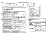
- a communication system 2 comprises a multi-function device 10 (a peripheral device of a PC 80) and the PC 80.
- the multi-function device 10 and the PC 80 are connected to a LAN 4.
- the multi-function device 10 and the PC 80 are capable of communicating with each other via the LAN 4.
- the multi-function device 10 is capable of performing a plurality of functions including a print function and a scan function.
- the multi-function device 10 comprises an operation unit 12, a display unit 14, a network interface 16, a print performing unit 18, a scan performing unit 20, and a controlling unit 30.
- the respective units 12 to 30 are connected to a bus line (reference numeral omitted).
- the operation unit 12 comprises a plurality of keys. By operating the operation unit 12, a user can input various instructions to the multi-function device 10.
- the display unit 14 is a display for displaying various types of information.
- the network interface 16 is connected to the LAN 4.
- the print performing unit 18 comprises a printing mechanism adopting an inkjet head system, a laser system, or the like, and performs printing in accordance with an instruction from the controlling unit 30.
- the scan performing unit 20 comprises a scanning mechanism such as a CCD, a CIS, or the like, and performs a scan of a document in accordance with an instruction from the controlling unit 30.
- the scan performing unit 20 comprises an FB (Flat Bed) mechanism 22.
- the FB mechanism 22 comprises a transparent plate (not shown) and a plurality of optical elements 24 aligned in a first direction.
- Each optical element 24 may be a CCD image sensor (Charge Coupled Device Image Sensor) or a CIS (Contact Image Sensor).
- the plurality of optical elements 24 is movable in a second direction that is perpendicular to the first direction (the direction in which the plurality of optical elements 24 is aligned). Therefore, by utilizing the FB mechanism 22, a color scan of a document placed on the transparent plate can be performed by moving the plurality of optical elements 24 in the second direction without having to move the document.
- a scan of a document placed on the transparent plate will be referred to as an "FB scan”.
- the scan performing unit 20 further comprises an ADF (Auto Document Feeder) mechanism 26.
- the ADF mechanism 26 is capable of moving a document in the second direction. Therefore, by utilizing the ADF mechanism 26, a color scan of a document can be performed by moving the document in the second direction without having to move the plurality of optical elements 24.
- a scan of a document conveyed by the ADF mechanism 26 will be referred to as an "ADF scan”.
- the ADF mechanism 26 comprises a document sensor 28. The document sensor 28 detects whether a document is placed on the ADF mechanism 26 or not, and supplies a detection result to the controlling unit 30.
- the controlling unit 30 comprises a CPU 32 and a memory 34.
- the CPU 32 performs various processes in accordance with a program (not shown) stored in the memory 34. Respective functions of an optical resolution determination unit 50, a scan controlling unit 52, an analysis performing unit 54, an output resolution determination unit 60, a conversion unit 62, a creation unit 64, and a judging unit 66 are realized due to the CPU 32 performing processes in accordance with the program.
- the analysis performing unit 54 comprises a first analysis unit 56 and a second analysis unit 58.
- the memory 34 is constituted by a nonvolatile memory, a volatile memory, or the like.
- the memory 34 comprises a scan setting storage area 36.
- the memory 34 further stores tables 40 (refer to FIGS. 3 and 7 ). Contents of information stored in the scan setting storage area 36 and contents of the tables 40 will be described in detail later.
- the tables 40 are stored in advance in the multi-function device 10 before shipping of the multi-function device 10.
- the multi-function device 10 may obtain (in other words, install) the tables 40 from a medium (for example, a USB memory) provided by a vendor of the multi-function device 10 or may obtain the tables 40 from a server provided by the vendor of the multi-function device 10.
- the PC 80 comprises a network interface 82 and a controlling unit 90.
- the PC 80 further comprises an operation unit and a display unit (both not shown).
- the network interface 82 is connected to the LAN 4.
- the controlling unit 90 comprises a CPU 92 and a memory 94.
- the CPU 92 performs various processes in accordance with a program (for example, a scanner driver 96) stored in the memory 94.
- the memory 94 is constituted by a nonvolatile memory, a volatile memory, or the like.
- the memory 94 stores the scanner driver 96 for utilizing the scan function of the multi-function device 10.
- the PC 80 obtains (in other words, installs) the scanner driver 96 from a medium that is shipped together with the multi-function device 10. However, alternatively, the PC 80 may obtain the scanner driver 96 from a server provided by the vendor of the multi-function device 10.
- FIG. 1 shows the tables 40 stored in the multi-function device 10 also being included in the scanner driver 96, this configuration is utilized in a modification which will be described later.
- the user After placing a document at a predetermined position of the multi-function device 10, the user operates the operation unit 12 of the multi-function device 10 to input an instruction to perform a color scan to the multi-function device 10. Moreover, in a case where the user desires to have an ADF scan performed, the user places the document on the ADF mechanism 26. On the other hand, in a case where the user desires to have an FB scan performed, the user places the document on the transparent plate of the FB mechanism 22.
- the controlling unit 30 causes the display unit 14 to display a selection screen that enables the user to select scan settings.
- a plurality of scan setting items including "file size”, “output resolution”, and "file format” is provided.
- File size refers to a file size of a file that is a creation object (hereinafter referred to as an "object file”).
- object file a creation object
- three file sizes (“large”, “medium”, and “small”) are adopted as setting values that can be designated by the user.
- two file sizes for example, “large” and “small” may be adopted or four or more file sizes may be adopted in a modification.
- Output resolution refers to a resolution indicated by image data included in the object file. Moreover, although a detailed description will be provided later, the "output resolution is to be distinguished from an optical resolution that is utilized when the scan performing unit 20 actually performs the scan. In the present embodiment, five output resolutions (“Auto”, “600 dpi”, “300 dpi”, “200 dpi”, and “100 dpi””) are adopted as setting values that can be designated by the user. As will be described later, “Auto” is a setting value that causes the multi-function device 10 to automatically determine an optical resolution and an output resolution.
- output resolutions (600 dpi”, “300 dpi”, “200 dpi”, and “100 dpi”) are adopted as output resolutions having specific numerical values, three or less or five or more output resolutions may be adopted in a modification.
- “File format” refers to a file format of the object file. More specifically, the "file format” is specified by an extension (for example, “.jpg”, “.pdf”, and “.xps”) included in a file name of the object file.
- three file formats (“JPEG (Joint Photographic Experts Group)", “XPS (XML Paper Specification)”, and “PDF (Portable Document Format)" are adopted as setting values that can be designated by the user.
- PDF is classified into six file formats (“PDF”, “PDF/A”, “Encryption PDF”, “Signature Enclosed PDF”, “Searchable PDF”, and “high-compression PDF”).
- PDF refers to a normal PDF that does not belong to the other five PDF types ("PDF/A”, "Encryption PDF”, and the like).
- PDF/A is an international standard established by the ISO and is a PDF designed for long-term data storage.
- the "encryption PDF” is a PDF in which data is encrypted using a password. Accordingly, in a case where selecting the encryption PDF, the user additionally inputs a password.
- the "signature Enclosed PDF” is a PDF enclosing a digital signature (for example, a time stamp). In a case where selecting the signature enclosed PDF, the user must install a digital signature in the multi-function device 10 in advance.
- the "searchable PDF” is a PDF enclosing characters included in a document (for example, characters read by an OCR (Optical Character Reader)) as searchable text data.
- the "high-compression PDF” is a PDF in which a character region and a background region of a document are separated from each other and separately compressed, with the character region compressed as a binary image and the background region compressed as a multi-level image. Moreover, a file size of a high-compression PDF is smaller than a file size of a normal PDF file.
- JPEG file having a "JPEG” file format includes image data compressed in accordance with a JPEG compression system (hereinafter referred to as "JPEG data").
- JPEG data image data compressed in accordance with a JPEG compression system
- XPS file having an "XPS” file format and a PDF file having a "PDF” file format also include JPEG data.
- compression rates of the JPEG data differ in correspondence with the three file sizes ("large”, “medium”, and “small”).
- the present embodiment defines the compression rate as follows. More specifically, the higher the compression rate, the smaller a data size (that is, the greater the degree of compression) of the JPEG data (that is, image data after compression). In other words, the lower the compression rate, the larger the data size (that is, the lower the degree of compression) of the JPEG data (that is, image data after compression).
- JPEG data compressed at a relatively low compression rate that is, JPEG data having a relatively large data size
- JPEG data compressed at a relatively high compression rate that is, JPEG data having a relatively small data size
- the user operates the operation unit 12 to designate one setting value for each of the plurality of scan setting items.
- the controlling unit 30 selects one file size from among the three file sizes, selects one output resolution from among the five output resolutions, and selects one file format from among the eight file formats.
- the controlling unit 30 further causes the scan setting storage area 36 (refer to FIG. 1 ) to store the selected file size, the selected output resolution, and the selected file format.
- the optical resolution determination unit 50 judges whether the selected output resolution stored in the scan setting storage area 36 is "Auto" or not. In a case where the selected output resolution is "Auto”, the optical resolution determination unit 50 makes a judgment of YES in S12 and proceeds to S20. On the other hand, in a case where the selected output resolution is not "Auto” or, in other words, in a case where the selected output resolution is one of the four output resolutions having specific numerical values, the optical resolution determination unit 50 makes a judgment of NO in S12 and proceeds to S30.
- the optical resolution determination unit 50 refers to an optical resolution determination table 42 (refer to FIG. 3 ) included in the tables 40 in the memory 34 so as to determine an optical resolution.
- the optical resolution determination table 42 is data representing a relationship among file sizes, file formats, and optical resolutions.
- Data in the table 42 is set so that the relatively larger the file size (in other words, "large” or “medium”), the relatively higher the optical resolution (in other words, "600 dpi” corresponding to "JPEG”), and the relatively smaller the file size (in other words, “small”), the relatively lower the optical resolution (in other words, "300 dpi” corresponding to "JPEG”). Accordingly, the multi-function device 10 is capable of appropriately determining the optical resolution in accordance with the file size selected by the user.
- the data in the table 42 is set so that in a case where the file size is "large” or “medium”, the optical resolution corresponding to "JPEG” (in other words, "600 dpi”) is higher than the optical resolution corresponding to "XPS” and "PDF” (in other words, "300 dpi”).
- "JPEG” is a file format not having a page concept (in other words, a file format incapable of including image data of a plurality of pages).
- "PDF" and "XPS” are file formats having the page concept (in other words, file formats capable of including image data of a plurality of pages). Therefore, the data in the table 42 is set so that an optical resolution corresponding to the file formats having the page concept (“PDF” and "XPS”) is lower than an optical resolution corresponding to the file format not having the page concept (“JPEG”).
- a scan of a document having a large number of pages may potentially be performed.
- the file size can be prevented from becoming excessively large in a case where the scan of the document having the large number of pages is performed.
- the optical resolution determination unit 50 determines an optical resolution by specifying the optical resolution corresponding to the selected file size and the selected file format stored in the scan setting storage area 36 from the optical resolution determination table 42. Accordingly, by utilizing the file size and the file format given from the user, the optical resolution determination unit 50 can appropriately determine an optical resolution to be utilized in the actual scan (hereinafter, referred to as a "determined optical resolution") from among the plurality of optical resolutions ("600 dpi" and "300 dpi").
- the scan controlling unit 52 causes the scan performing unit 20 to perform the color scan of the document.
- the document sensor 28 supplies a detection signal indicating that the document is placed on the ADF mechanism 26 to the controlling unit 30.
- the scan controlling unit 52 supplies the scan performing unit 20 with a signal for operating the ADF mechanism 26 and causes the ADF mechanism 26 to convey the document in the aforementioned second direction.
- the scan controlling unit 52 supplies the scan performing unit 20 with a signal for causing the plurality of optical elements 24 to perform the color scan in accordance with the determined optical resolution which had been determined in S20 (in other words, "600 dpi" or "300 dpi”). In doing so, the scan controlling unit 52 does not supply the scan performing unit 20 with a signal for moving the plurality of optical elements 24 in the second direction. Accordingly, the plurality of optical elements 24 in a stationary state performs the color scan of the document conveyed by the ADF mechanism 26 in accordance with the determined optical resolution which had been determined in S20. In other words, the ADF scan is performed.
- the document sensor 28 does not supply the aforementioned detection signal to the controlling unit 30.
- the scan controlling unit 52 supplies the scan performing unit 20 with a signal for causing the plurality of optical elements 24 to perform the color scan in accordance with the determined optical resolution which had been determined in S20, and a signal for moving the plurality of optical elements 24 in the second direction. Accordingly, the plurality of optical elements 24 in a moving state performs the color scan of the document placed on the transparent plate in accordance with the determined optical resolution which had been determined in S20. In other words, the FB scan is performed.
- the scan controlling unit 52 can obtain scan data (in other words, color image data) indicating the determined optical resolution determined which had been determined in S20 from the scan performing unit 20.
- the analysis performing unit 54 performs an analysis of the scan data
- the output resolution determination unit 60 determines an output resolution (hereinafter referred to as a "determined output resolution") by utilizing a result of the analysis. Contents of the analysis process performed in S24 will be described in detail later.
- the conversion unit 62 and the creation unit 64 create an object file including image data indicating the determined output resolution.
- the conversion unit 62 judges whether or not the determined optical resolution that had been determined in S20 and the determined output resolution that had been determined in S24 are identical to each other.
- the conversion unit 62 resizes (in other words, converts) the scan data indicating the determined optical resolution (for example, "600 dpi") into scan data indicating the determined output resolution (for example, "300 dpi"). While a bilinear method is adopted as a resizing method in the present embodiment, other methods may be adopted in a modification.
- the conversion unit 62 does not resize (convert) the scan data.
- the scan data indicating the determined optical resolution becomes equal to the image data indicating the determined output resolution.
- the creation unit 64 compresses the image data indicating the determined output resolution in correspondence with the selected file size stored in the scan setting storage area 36. Moreover, the creation unit 64 compresses the image data by utilizing the JPEG compression system. The creation unit 64 compresses the image data at a first compression rate in a case where the selected file size is "large”, compresses the image data at a second compression rate that is higher than the first compression rate in a case where the selected file size is "medium”, and compresses the image data at a third compression rate that is higher than the second compression rate in a case where the selected file size is "small”. Accordingly, JPEG data is created.
- the creation unit 64 further creates data corresponding to the selected file format stored in the scan setting storage area 36.
- the selected file format is JPEG
- the creation unit 64 creates a file name including the JPEG extension (".jpg"), a JPEG header and a JPEG footer, and the like. Accordingly, an object file having a JPEG file format is completed.
- the creation unit 64 creates a file name including the XPS extension (".xps"), a JPEG header and a JPEG footer, an XPS header and an XPS footer, data indicating a page number, and the like. Accordingly, an object file having an XPS file format is completed.
- the creation unit 64 creates a file name including the PDF extension (".pdf"), a JPEG header and a JPEG footer, a PDF header and a PDF footer, data indicating a page number, and the like.
- the creation unit 64 creates data in correspondence with the PDF type (PDF/A, Encryption PDF, Signature Enclosed PDF, and the like) by utilizing a known method.
- the creation unit 64 encloses an digital signature in the object file. Accordingly, an object file having a PDF file format is completed.
- JPEG is a file format not having the page concept. Therefore, for example, in a case where a scan of a document including two or more pages is performed, a JPEG object file representing a single-page document is created for each document page.
- the selected file format is JPEG and a scan of a document including Y-number of pages (where Y is an integer equal to or greater than 2) is performed, the creation unit 64 creates Y-number of JPEG object files respectively having different file names.
- PDF and XPS are file formats having a page concept. Therefore, in a case where the selected file format is PDF or XPS and a scan of a document including Y-number, of pages (where Y is an integer equal to or greater than 2) is performed, the creation unit 64 creates a single object file (in other words, a PDF file or an XPS file) including the JPEG data corresponding to Y-number pages representing the document including the Y-number of pages. Once S26 is concluded, a transfer is made to S40.
- the optical resolution determination unit 50 determines an optical resolution corresponding to the selected output resolution stored in the scan setting storage area 36.
- a relationship between output resolutions and optical resolutions has been determined in advance. More specifically, in a case where the selected output resolution is "600 dpi", the optical resolution determination unit 50 determines "600 dpi” as the optical resolution. In addition, in a case where the selected output resolution is any of "300 dpi", “200 dpi", and "100 dpi", the optical resolution determination unit 50 determines "300 dpi" as the optical resolution.
- the scan controlling unit 52 causes the scan performing unit 20 to perform a scan in accordance with the determined optical resolution which had been determined in S30 in the same manner as in S22.
- the conversion unit 62 and the creation unit 64 convert the scan data so as to create an object file in the same manner as in S26.
- the controlling unit 30 transmits the object file created in S26 or S34 to a destination (for example, a USB memory, the PC 80, a predetermined server, or the like) selected in advance by the user. Accordingly, the user can cause an image represented by the JPEG data included in the object file (in other words, an image representing the document that is the scan object) to be outputted (displayed, printed, or the like).
- a destination for example, a USB memory, the PC 80, a predetermined server, or the like
- the analysis performing unit 54 performs a character analysis of the scan data. More specifically, in S100, the second analysis unit 58 (refer to FIG. 1 ) performs a character analysis of scan data to calculate a size of the smallest character included in the document (hereinafter referred to as the "smallest character point") as an index value indicating a configuration of the character included in the document.
- the second analysis unit 58 performs a character analysis of scan data to calculate a size of the smallest character included in the document (hereinafter referred to as the "smallest character point") as an index value indicating a configuration of the character included in the document.
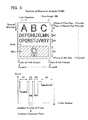
- FIG. 5 shows an example of a scan image 100 represented by the scan data obtained by the scan of the document performed in S22 in FIG. 2 .
- the document includes alphabetical characters "A” to "Y” and a natural image in which a flower is present in a blue background.
- the characters "A” to “Y” are in black and the surroundings of the characters “A” to “Y” (in other words, a background of the document) are in white.
- "A” to “C” have relatively large character sizes and "D” to "Y” have relatively small character sizes.
- each of the plurality of pixels constituting the scan data has an RGB pixel value.
- the second analysis unit 58 first calculates a value related to a luminance of a pixel for each of the plurality of pixels constituting the scan data.
- a V value that is utilized in an HSV color space or a value related to luminance in another color space may be utilized as the value related to luminance.
- the second analysis unit 58 calculates Yrsum1 that is a sum of Y values of the respective pixels constituting the pixels of a first row. In a similar manner, the second analysis unit 58 also calculates Yrsum2 and the like for the pixels of the second and subsequent rows. Accordingly, M-number (where M is an integer equal to or larger than 2) of Yrsums (Yrsum1 to YrsumM) corresponding to pixels of M-number of rows which constitute the scan data are calculated.
- the second analysis unit 58 creates a histogram of the M-number of Yrsums.
- the pixels of the first row are pixels representing only the white background of the document. Therefore, since the luminance of the pixels of the first row is high, Yrsum1 of the pixels of the first row has a relatively large value.
- the pixels of the second row are pixels representing a portion of the black characters "A" to "C". Therefore, since the luminance of the pixels of the second row is lower than the luminance of the pixels of the first row which represent only the white background, Yrsum2 of the pixels of the second row has a relatively small value.
- Yrsum of the pixels representing the characters "D” to “N” has a relatively small value
- Yrsum of the pixels representing the characters “O” to “Y” also has a relatively small value
- Yrsum of the pixels representing the natural image including a blue background also has a relatively small value.
- the second analysis unit 58 identifies a number of consecutive rows (hereinafter referred to as "consecutive row numbers") which have a Yrsum equal to or smaller than a predetermined value.
- the second analysis unit 58 identifies consecutive row numbers corresponding to an arrow A1 representing the characters "A” to “C”, consecutive row numbers corresponding to an arrow A2 representing the characters “D” to “N”, and consecutive row numbers corresponding to an arrow A3 representing the characters “O” to "Y”. Furthermore, since the Yrsum of the pixels representing the natural image is also a relatively small value, the second analysis unit 58 identifies consecutive row numbers corresponding to an arrow A4 despite the natural image not including any characters.
- the second analysis unit 58 Since the second analysis unit 58 is already aware of unit information for converting a single row into a character size (in other words, unit information indicating how many points a single row corresponds to), the second analysis unit 58 is capable of calculating a size of the smallest character (for example, "D") included in the document (in other words, the smallest character point) by multiplying the consecutive row numbers corresponding to the arrow A2 with the unit information.
- a size of the smallest character for example, "D”
- the second analysis unit 58 also performs an analysis along the column direction (in other words, calculations of Ycsum1 to YcsumN which are sums of Y values of the respective pixels, identification of the number of pixels (that is, consecutive column numbers) having the Ycsum equal to or smaller than a predetermined value, and the like).
- an analysis along the column direction in other words, calculations of Ycsum1 to YcsumN which are sums of Y values of the respective pixels, identification of the number of pixels (that is, consecutive column numbers) having the Ycsum equal to or smaller than a predetermined value, and the like.
- N is an integer equal to or greater than 2
- the second analysis unit 58 judges in an analysis along the column direction that a character is not included in the document. However, as described above, since the smallest character point in an analysis along the row direction is calculated, the second analysis unit 58 adopts the smallest character point as a result of the character analysis of S100.
- the second analysis unit 58 judges that a character is not included in the document in both the analysis along the row direction and the analysis along the column direction. In this case, the second analysis unit 58 judges that a character is not included in the document as a result of the character analysis in S100.
- the smallest character point may be calculated in the analysis along the row direction and the smallest character point may also be calculated in the analysis along the column direction. In this case, the second analysis unit 58 adopts whichever is the smaller among the two smallest character points as the result of the character analysis in S100.
- the judging unit 66 judges whether a photo analysis in S106 is to be performed by the first analysis unit 56 (refer to FIG. 1 ) or not by utilizing the smallest character point obtained in the character analysis in S100.
- the judging unit 66 judges that the photo analysis in S106 is not to be performed in a case where the smallest character point is relatively small (in a case where 5 pt > smallest character point). Supposing that a relatively low output resolution is adopted in a case where the smallest character point is relatively small, the user is more likely to recognize that image quality is low. Therefore, in the case where the smallest character point is relatively small, since it is obvious that a relatively high output resolution must be adopted even without performing the photo analysis, in S102, the judging unit 66 judges that the photo analysis is not to be performed.
- the photo analysis must be further performed to judge whether such an output resolution is appropriate or not. Therefore, in the case where the smallest character point is relatively large, in S102, the judging unit 66 judges that the photo analysis is to be performed. Moreover, in the case where it is judged that a character is not included in the document, the result of the character analysis alone is insufficient to appropriately determine the output resolution. Therefore, in the case where it is judged that a character is not included in the document, in S102, the judging unit 66 judges that the photo analysis is to be performed.
- the judging unit 66 judges in S102 that the photo analysis is to be performed, the judging unit 66 sets ON as a photo analysis flag (not shown) in the memory 34, and in the case where it is judged that the photo analysis is not to be performed, the judging unit 66 sets OFF as the photo analysis flag.
- the judging unit 66 judges whether ON has been set as the photo analysis flag or not.
- the analysis performing unit 54 performs the photo analysis of the scan data. More specifically, in S106, the first analysis unit 56 performs the photo analysis of the scan data to calculate an edge rate ER (refer to FIG. 6 ) that indicates a fineness of the document as the index value for classifying a document including a natural image.
- the edge rate ER (refer to FIG. 6 ) that indicates a fineness of the document as the index value for classifying a document including a natural image.
- the first analysis unit 56 does not calculate the edge rate ER. In this case, processing load can be reduced.
- the first analysis unit 56 determines whether the pixel is an edge pixel or a non-edge pixel, and calculates the edge rate ER that is a proportion of the edge pixels among the scan data.
- an edge refers to a portion whose brightness (luminance) changes significantly in the image. Therefore, the edge pixel is a pixel having a luminance value that significantly differs from surrounding pixels. Since discrimination methods of the edge pixels and non-edge pixels are well known, contents of the photo analysis will be briefly described herein.
- the first analysis unit 56 first creates the YCC data by converting each of the plurality of pixels constituting the scan data (pixels represented by the RGB values) into a pixel in the YCC color space. Moreover, a known mathematical formula is utilized for the conversion from RGB to YCC.
- the first analysis unit 56 applies a known filter for discriminating edge pixels from non-edge pixels (for example, a Sobel filter or a Laplacian filter) to the YCC data. Accordingly, for each of the plurality of pixels, the first analysis unit 56 can determine whether the pixel is the edge pixel (edge ON) or the non-edge pixel (edge OFF).
- a known filter for discriminating edge pixels from non-edge pixels for example, a Sobel filter or a Laplacian filter
- the first analysis unit 56 divides the number of pixels determined as the edge ON (in other words, the number of the edge pixels) by the total number of pixels constituting the YCC data (in other words, the total number of pixels constituting the scan data). The first analysis unit 56 then multiplies the value obtained by the division by 100 to calculate the edge rate ER (%).
- a natural image with a relatively small amount of variation in brightness such as an ordinary scenery image (for example, mountains, sea, or the like) has a low edge rate ER.
- the natural image having a relatively low fineness has the low edge rate ER.
- a natural image with a relatively large amount of variation in brightness such as a natural image including a building or a natural image including a plurality of people has a high edge rate ER.
- the natural image having a relatively high fineness has the high edge rate ER. Therefore, the edge rate ER is an index value indicating the fineness of the document.
- a document is classified into any of three fineness stages (high fineness, medium fineness, and low fineness) in correspondence with the edge rate ER.
- the document representing the scan image 100 shown in FIG. 5 includes a natural image with a relatively low fineness.
- the document representing the scan image 100 also includes a plurality of characters. Since a boundary between the character and the background has a large amount of variation in brightness, the number of edge pixels increases if a character is included. Therefore, for example, the document representing the scan image 100 may be classified in the medium fineness.
- the output resolution determination unit 60 determines the output resolution based on the result of the character analysis of S100 and the result of the photo analysis of S106 (in the case where S106 is performed). In the case where the photo analysis of S106 is performed, the output resolution determination unit 60 determines the output resolution by utilizing the smallest character point obtained in the character analysis of S100 and the edge rate ER obtained in the photo analysis of S106. On the other hand, in the case where the photo analysis of S106 is not performed, the output resolution determination unit 60 determines the output resolution by utilizing only the smallest character point obtained in the character analysis of S100 (in other words, not utilizing the edge rate ER).
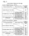
- the optical resolution determination unit 60 refers to an output resolution determination table 44a (refer to FIG. 7 ) included in the tables 40 in the memory 34 so as to determine the output resolution.
- the output resolution determination table 44a is data representing a relationship among the smallest character points, the edge rates ER, and the output resolutions.
- the determined optical resolution the optical resolution determined in S20 in FIG. 2
- the upper table in FIG. 7 is used, and in the case where the determined optical resolution is 600 dpi, the lower table in FIG. 7 is used.
- the output resolution determination table 44a a field of the photo analysis result corresponding to the smallest character point ⁇ 5 pt remains blank.
- Data in the table 44a is set so that the relatively smaller the smallest character point, the relatively higher the output resolution, and the relatively larger the smallest character point, the relatively lower the output resolution.
- a smaller value for example, 100 dpi representing low fineness
- a relatively high output resolution is set so that the user does not receive a sense of low image quality.
- data in the table 44a is set so that output resolution does not assume a larger value than a value that is identical to the determined optical resolution in order to avoid having to perform an interpolation process of the image data. Therefore, in the case where the smallest character point ⁇ 5 pt, the same value as the determined optical resolution is set as the output resolution.
- the data in the table 44a is set so that the relatively higher the edge rate ER, the relatively higher the output resolution, and the relatively lower the edge rate ER, the relatively lower the output resolution.
- the same value for example, 300 dpi
- the same value for example, 300 dpi
- a smaller value for example, 200 dpi than the same value as the determined optical resolution is set as the output resolution.
- a relatively high output resolution is set so that the user does not receive the sense of low image quality.
- the edge rate ER > 2.8 in other words, in a case of high fineness
- the same value (for example, 300 dpi) as the determined optical resolution is set as the output resolution. Consequently, an extremely high output resolution can be adopted in the case where the edge rate ER > 2.8 so that the user can be prevented from receiving the sense of low image quality.
- the data in the table 44a is set so that even if the smallest character point is the same, output resolutions differ in a case where the fineness differs.
- the table corresponding to determined optical resolution 300 dpi
- the output resolution corresponding to the high fineness (300 dpi) and the output resolution corresponding to the medium fineness (200 dpi) differ from each other.
- the multi-function device 10 is capable of appropriately determining the output resolution in accordance with the fineness of the document in the case where the smallest character point is the same.
- the data in the table 44a is set so that even if the fineness is the same, output resolutions differ in a case where the smallest character point differs.
- the output resolution corresponding to 5 pt ⁇ the smallest character point ⁇ 10.5 pt (200 dpi) and the output resolution corresponding to 10.5 pt ⁇ the smallest character point (100 dpi) differ from each other.
- the multi-function device 10 is capable of appropriately determining the output resolution in accordance with the smallest character point in a case where the fineness of the document is the same.
- the output resolution determination unit 60 determines the output resolution by identifying the output resolution corresponding to the determined optical resolution, the smallest character point, and the edge rate ER from the output resolution determination table 44a. Accordingly, the output resolution determination unit 60 is capable of appropriately determining the output resolution.
- the analysis process is concluded. As described earlier, in S26 of FIG. 2 , the object file including the image data indicating the output resolution determined in S108 is created. Therefore, the user is able to utilize the object file including the image data indicating an appropriate output resolution (for example, output the image).
- the multi-function device 10 is capable of appropriately determining the optical resolution to be utilized in the actual scan by utilizing the file size and the file format given from the user.
- the optical resolution of 600 dpi that is the highest value may be determined
- the optical resolution of 300 dpi may also be determined.
- the scan of the document can be performed at a relatively high speed, and the difference between the optical resolution and the output resolution can be prevented from becoming large.
- the multi-function device 10 is capable of appropriately determining the output resolution based on the result of the analysis of the scan data. Therefore, the multi-function device 10 is capable of appropriately determining both the optical resolution and the output resolution.
- the multi-function device 10 determines the output resolution by utilizing the edge rate ER for classifying the document including the natural image or, in other words, by utilizing the edge rate ER for classifying the document from the perspective of fineness. Therefore, the multi-function device 10 is capable of appropriately determining the output resolution for the scan data representing the document including the natural image.
- the multi-function device 10 is an example of an "image processing device".
- the optical resolution determined in S20 of FIG. 2 is an example of a "specific optical resolution”.
- the edge rate ER and the smallest character point are, respectively, examples of a "first type of index value” and a "second type of index value”.
- 300 dpi shown in FIG. 7 300 dpi corresponding to the high fineness and 200 dpi corresponding to the medium fineness in a case where 5 pt ⁇ the smallest character point ⁇ 10.5 pt are, respectively, examples of a "first value” and a "second value”.
- the low fineness is an example of a "first fineness”
- 10.5 pt ⁇ the smallest character point and 5 pt ⁇ the smallest character point ⁇ 10.5 pt are, respectively, examples of a "first configuration" and a "second configuration”.
- 100 dpi and 200 dpi are, respectively, examples of a "third value” and a "fourth value”.
- the low fineness and the medium fineness are examples of a "first fineness” and a "second fineness”
- 10.5 pt ⁇ the smallest character point is an example of a "first configuration”.
- 100 dpi and 200 dpi are, respectively, examples of a "third value” and a "fifth value”.
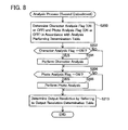
- an analysis process of FIG. 8 is performed in place of the analysis process of FIG. 4 .
- the judging unit 66 judges whether the analysis is to be performed or not based on a combination of which of an ADF scan or an FB scan is performed and the selected file format stored in the scan setting storage area 36.
- the judging unit 66 refers to an analysis performing determination table 46 (refer to FIG. 9 ) included in the tables 40 in the memory 34 so as to determine whether each of the character analysis and the photo analysis is to be performed or not.
- the analysis performing determination table 46 is data representing a relationship among a document setting position (in other words, the ADF scan or the FB scan), a selected file format, whether the character analysis is to be performed or not (ON or OFF), and whether the photo analysis is to be performed or not (ON or OFF).
- a remarks column is provided in FIG. 9 to facilitate technical understanding, the actual data does not include the remarks column.
- a user is likely to desire performing the ADF scan on a document including a character and is likely to desire performing the FB scan on a photograph or the like that represents a natural image. Therefore, in the case where the user desires to perform the ADF scan, the document is likely to include a character. To this end, in the case where the ADF scan is to be performed, the character analysis for calculating the smallest character point that is an index value indicating a configuration of the character included in the document is favorably performed. On the other hand, in the case where the user desires to perform the FB scan, the document is likely to include a natural image. Therefore, in the case where the FB scan is to be performed, the photo analysis for calculating an edge rate ER that is an index value for classifying a document including a natural image is favorably performed.
- the multi-function device 10 is capable of appropriately determining the output resolution by utilizing the result of the character analysis in the case where the ADF scan is performed.
- the multi-function device 10 since the multi-function device 10 does not perform the character analysis in the case where the FB scan is performed, the multi-function device 10 is capable of reducing the processing load.
- the data in the table 46 is set so that the photo analysis is performed regardless of which of the ADF scan and the FB scan is performed in the case where the selected file format is JPEG.
- the multi-function device 10 is capable of appropriately determining the output resolution by utilizing the result of the photo analysis in the case where the FB scan is performed.
- the multi-function device 10 since the multi-function device 10 does not perform the photo analysis in the case where the ADF scan is performed, the multi-function device 10 is capable of reducing processing load.
- the data in the table 46 is set so that the character analysis is performed regardless of which of the ADF scan and the FB scan is performed in the case where the selected file format is XPS or PDF.
- the multi-function device 10 performs neither the character analysis nor the photo analysis in the case where PDF/A is selected, the multi-function device 10 is capable of reducing the processing load.
- a high resolution equal to or higher than 300 dpi be set for Signature Enclosed PDF. Therefore, in a case where the selected file format is Signature Enclosed PDF, a high output resolution equal to or higher than 300 dpi is favorably determined even without performing the character analysis and the photo analysis.
- a high output resolution having the same value as the optical resolution is determined.
- a smaller value than the value that is identical to the optical resolution may be determined as the output resolution.
- the data in the table 46 is set so that in the case where the selected file format is Signature Enclosed PDF, neither the character analysis nor the photo analysis is performed. According to this configuration, since the multi-function device 10 performs neither the character analysis nor the photo analysis in the case where Signature Enclosed PDF is selected, the multi-function device 10 is capable of reducing the processing load.
- the data in the table 46 is set so that the character analysis is performed but the photo analysis is not performed regardless of which of the ADF scan and the FB scan is performed in the case where the selected file format is Encryption PDF or Searchable PDF.
- the document may include a character and may also include a natural image.
- the data in the table 46 is set so that both the character analysis and the photo analysis are performed regardless of which of the ADF scan and the FB scan is performed in the case where the selected file format is high-compression PDF.
- the judging unit 66 sets ON or OFF as a character analysis flag (not shown) in the memory 34.
- the judging unit 66 sets ON or OFF as a photo analysis flag (not shown) in the memory 34.
- the judging unit 66 judges whether ON has been set as the character analysis flag or not.
- the second analysis unit 58 performs the character analysis of the scan data. Contents of the character analysis are similar to those in the first embodiment.
- the processing load can be reduced.
- the judging unit 66 judges whether ON has been set as the photo analysis flag or not.
- ON has been set as the photo analysis flag
- the first analysis unit 56 performs the photo analysis of the scan data. Contents of the photo analysis are similar to those in the first embodiment.
- OFF has been set as the photo analysis flag
- the processing load can be reduced.
- the output resolution determination unit 60 determines the output resolution. In the case where both the character analysis in S204 and the photo analysis in S206 have been performed, the output resolution determination unit 60 determines the output resolution by referring to the table 44a shown in FIG. 7 and utilizing both the result of the character analysis (in other words, the smallest character point) and the result of the photo analysis (in other words, the edge rate ER). In the case where only the character analysis in S204 is performed, the output resolution determination unit 60 determines the output resolution by referring to the table 44b shown in FIG. 10 and utilizing the result of the character analysis without utilizing the result of the photo analysis. In the case where only the photo analysis in S208 is performed, the output resolution determination unit 60 determines the output resolution by referring to the table 44b shown in FIG. 10 and utilizing the result of the photo analysis without utilizing the result of the character analysis.
- the data in the table 44b shown in FIG. 10 is set so that the relatively smaller the smallest character point, the relatively higher the output resolution, and the relatively larger the smallest character point, the relatively lower the output resolution. Furthermore, in the table 44b, no character is classified in a same category as 10.5 pt ⁇ the smallest character point. In addition, the data in the table 44b is set so that the relatively higher the edge rate ER, the relatively higher the output resolution, and the relatively lower the edge rate ER, the relatively lower the output resolution.
- the output resolution determination unit 60 determines the output resolution by utilizing neither the result of the character analysis nor the result of the photo analysis. In other words, the output resolution determination unit 60 determines a value that is identical to the optical resolution as the output resolution in the case where the selected file format is PDF/A or Signature Enclosed PDF. According to this configuration, the multi-function device 10 is capable of appropriately determining the output resolution in the case where PDF/A or Signature Enclosed PDF is selected.
- the multi-function device 10 is capable of appropriately determining the optical resolution to be utilized in the actual scan by utilizing the file size and the file format given from the user (S20 in FIG. 2 ), and is also capable of appropriately determining the output resolution based on the result of the analysis of the scan data (the analysis processes in FIG. 9 ). Therefore, the multi-function device 10 is capable of appropriately determining both the optical resolution and the output resolution. In addition, the multi-function device 10 is capable of appropriately determining the output resolution for the scan data representing the document including the natural image.
- the multi-function device 10 is capable of appropriately judging whether each of the character analysis and the photo analysis is to be performed or not based on which of the ADF scan and the FB scan is to be performed and based on which file format is to be selected. In the case where it is judged that the character analysis is to be performed, the multi-function device 10 is capable of performing the character analysis and appropriately determining the output resolution by utilizing the result of the character analysis. In a similar manner, in the case where it is judged that the photo analysis is to be performed, the multi-function device 10 is capable of performing the photo analysis and appropriately determining the output resolution by utilizing the result of the photo analysis. On the other hand, since the multi-function device 10 does not perform the character analysis and/or the photo analysis in the case where it is judged that the character analysis and/or the photo analysis are not to be performed, the multi-function device 10 is capable of reducing the processing load.
- the user operates the operation unit 12 of the multi-function device 10 to input an instruction for performing the scan to the multi-function device 10.
- the first and second embodiments are embodiments of a so-called push scan.
- the user may operate an operation unit (not shown) of the PC 80 to input the instruction to perform the scan to the PC 80.
- the PC 80 transmits the instruction to perform the scan to the multi-function device 10 in accordance with the scanner driver 96.
- a so-called pull scan is performed.
- the respective units 50 to 66 may be realized by a CPU (not shown) of the PC 80 by executing processes in accordance with the scanner driver 96.
- the PC 80 may comprise the plurality of units 50 to 66.
- the respective determination units 50, 60 and the judging unit 66 of the PC 80 may determine an optical resolution, determine an output resolution, judge performance of a character analysis, and judge performance of a photo analysis by utilizing tables 40 included in the scanner driver 96.
- the PC 80 is an example of an "image processing device".
- a portion of units among the plurality of units 50 to 66 may be realized by the multi-function device 10 by executing processes in accordance with a program in the memory 34, and other units of the plurality of units 50 to 66 may be realized by the CPU of the PC 80 by executing processes in accordance with the scanner driver 96.
- a combination of the multi-function device 10 and the PC 80 is an example of an "image processing device".
- the "image processing device” may be realized by a single device as is the case in the respective embodiments and the first modification described above, or may be realized by a combination of two or more devices as is the case in the present modification.
- the smallest character point is calculated in the character analysis.
- the character analysis may calculate an index value indicating a thinness of the character included in the document, an index value indicating a color of the character included in the document, or an index value indicating a concentration of the character included in the document.
- the second analysis unit 58 need only calculate the index value indicating the configuration of the character included in the document.
- the edge rate ER that indicates the fineness of the document is calculated in the photo analysis.
- the index value that indicates the fineness of the document for example, an index value indicating whether a person is included in the natural image or not may be calculated in the photo analysis.
- the first analysis unit 56 may judge that a person is included in the natural image in a case where there are a predetermined number or more of a specific pixel (in other words, a pixel indicating both "a hue of x or higher and y or lower” and "a chroma of a or higher and b or lower") among the plurality of pixels constituting the scan data, and judges that a person is not included in the natural image in a case where there is not a predetermined number or more of the specific pixel.
- a specific pixel in other words, a pixel indicating both "a hue of x or higher and y or lower” and "a chroma of a or higher and b or lower
- the output resolution determination unit 60 may determine the output resolution in the same manner as the "high fineness" in the respective embodiments, and in the case where it is judged that a person is not included in the natural image, the output resolution determination unit 60 may determine the output resolution in the same manner as the "low fineness” in the respective embodiments.
- the first analysis unit 56 may calculate an index value that indicates the number of colors included (how many different colors are being utilized) in the natural image.
- the output resolution determination unit 60 may determine the output resolution in the same manner as the "high fineness" in the respective embodiments, and in a case where the number of colors included in the natural image is smaller than the predetermined number, the output resolution determination unit 60 may determine the output resolution in the same manner as the "low fineness" in the respective embodiments.
- the first analysis unit 56 need only calculate the index value for classifying the document including the natural image.
- the second analysis unit 58 performs the character analysis and, subsequently, the first analysis unit 56 performs the photo analysis.
- the first analysis unit 56 may perform the photo analysis and, subsequently, the second analysis unit 58 may perform the character analysis.
- both the character analysis and the photo analysis are performed.
- only the photo analysis may be performed without performing the character analysis (in other words, S100 to S104 in FIG. 4 may be omitted).
- two or more types of analyses including the photo analysis and a type of analysis that differs from the character analysis may be performed.
- the image processing device need only comprise the first analysis unit and the second analysis unit need not be provided.
- the optical resolution that is utilized in an actual scan is determined from a plurality of optical resolutions.
- a configuration may be adopted in which a scan of a document is performed solely in accordance with an optical resolution indicating a single value that is determined in advance.
- the optical resolution may be fixed.
- the single value determined in advance is an example of a "specific optical resolution".
- the respective functions of the plurality of units 50 to 66 are realized by the CPU 32 of the multi-function device 10 by executing processes in accordance with a program.
- at least one unit among the plurality of units 50 to 66 may be realized by hardware such as a logic circuit.
Landscapes
- Engineering & Computer Science (AREA)
- Multimedia (AREA)
- Computer Vision & Pattern Recognition (AREA)
- Signal Processing (AREA)
- Artificial Intelligence (AREA)
- Physics & Mathematics (AREA)
- General Physics & Mathematics (AREA)
- Theoretical Computer Science (AREA)
- Editing Of Facsimile Originals (AREA)
- Image Processing (AREA)
Abstract
Description
- The technique disclosed in the present specification relates to an image processing device for converting scan data into image data indicating an output resolution.
- For example, the
US patent application publication No. 2009/0303508 discloses a digital multi-function device comprising a scan function. The digital multi-function device performs a scan of a document so as to create scan data. Next, the digital multi-function device performs an analysis of the scan data so as to calculate a size of the smallest character included in the document. In a case where the size of the smallest character is relatively small, the digital multi-function device determines a relatively high output resolution, and in a case where the size of the smallest character is relatively large, the digital multi-function device determines a relatively low output resolution. The digital multi-function device then converts scan data into image data indicating the determined output resolution. - With the technique described above, an output resolution may not be appropriately determined as to scan data representing a document not including a character (for example, a document only including a natural image (a photograph or the like)) or scan data representing a document including both a character and a natural image. The present specification provides a technique that may appropriately determine an output resolution.
- The present specification discloses an image processing device. The image processing device may comprise: a first analysis unit configured to calculate, by utilizing scan data obtained by a scan of a document including a natural image in accordance with a specific optical resolution, a first type of index value for classifying the document; an output resolution determination unit configured to determine an output resolution by utilizing the first type of index value, the output resolution being a resolution for image data obtained by utilizing the scan data; a conversion unit configured to convert the scan data indicating the specific optical resolution into the image data indicating the output resolution in a case where the output resolution is not identical to the specific optical resolution; and a creation unit configured to create a file including the image data indicating the output resolution.
- According to the configuration described above, the image processing device determines the output resolution by utilizing the first type of index value for classifying the document including the nature image. Therefore, the image processing device may appropriately determine the output resolution for the scan data representing the document including the natural image.
- The first type of index value may be an index value indicating a fineness of the document. The output resolution determination unit may be configured to: determine a first value as the output resolution in a case where the first type of index value indicates that the document has a relatively high fineness, the first value being equal to or lower than the specific optical resolution; and determine a second value as the output resolution in a case where the first type of index value indicates that the document has a relatively low fineness, the second value being lower than the first value. Supposing that a configuration is adopted in which a file including image data indicating a relatively low output resolution is created despite a document having a relatively high fineness, the user is more likely to recognize that image quality is low when an image represented by the image data is being outputted (displayed, printed, or the like). Therefore, in the configuration described above, in a case where the document has a relatively high fineness, the image processing device creates a file including image data indicating a relatively high output resolution. On the other hand, by creating a file including image data indicating a relatively low output resolution in a case where the document has a relatively low fineness, the image processing device may prevent a file size from becoming excessively large.
- The first value may be the same value as the specific optical resolution. According to this configuration, in a case where the document has a relatively high fineness, the image processing device is capable of creating a file including image data indicating a high output resolution having the same value as the specific optical resolution.
- The image processing device may further comprises: a second analysis unit configured to calculate, by utilizing the scan data, a second type of index value indicating a configuration of a character included in the document. The output resolution determination unit may be configured to determine the output resolution by utilizing the first type of index value and the second type of index value. According to this configuration, the image processing device may appropriately determine the output resolution by utilizing the first type of index value and the second type of index value.
- The output resolution determination unit may be configured to: determine a third value as the output resolution in a case where the first type of index value indicates that the fineness of the document is a first fineness, and the second type of index value indicates that the configuration of the character included in the document is a first configuration; and determine a fourth value being different from the third value as the output resolution in a case where the first type of index value indicates that the fineness of the document is the first fineness, and the second type of index value indicates that the configuration of the character included in the document is a second configuration being different from the first configuration. According to this configuration, in a case where the fineness of the document is the first fineness, the image processing device may appropriately determine the output resolution in accordance with the configuration of the character included in the document.
- The output resolution determination unit may be configured to: determine a third value as the output resolution in a case where the first type of index value indicates that the fineness of the document is a first fineness, and the second type of index value indicates that the configuration of the character included in the document is a first configuration; and determine a fifth value being different from the third value as the output resolution in a case where the first type of index value indicates that the fineness of the document is a second fineness being different from the first fineness, and the second type of index value indicates that the configuration of the character included in the document is the first configuration. According to this configuration, in a case where a configuration of a character included in the document is a first configuration, the image processing device may appropriately determine the output resolution in accordance with the fineness of the document.
- The image processing device may further comprises: a judging unit configured to judge, by utilizing the second type of index value, whether the first analysis unit should calculate the first type of index value. The first analysis unit may be configured to: calculate the first type of index value in a case where it is judged that the first analysis unit should calculate the first type of index value; and not calculate the first type of index value in a case where it is judged that the first analysis unit should not calculate the first type of index value. The output resolution determination unit may be configured to: determine the output resolution by utilizing the first type of index value and the second type of index value in the case where it is judged that the first analysis unit should calculate the first type of index value, and determine the output resolution by utilizing the second type of index value without utilizing the first type of index value in the case where it is judged that the first analysis unit should not calculate the first type of index value. According to this configuration, the image processing device is capable of judging whether the first type of index value is to be calculated or not by utilizing the second type of index value. The image processing device calculates the first type of index value in a case where it is judged that the first type of index value should be calculated, and may appropriately determine the output resolution by utilizing both the first type of index value and the second type of index value. On the other hand, since the image processing device does not calculate the first type of index value in a case where it is judged that the first type of index value should not to be calculated, processing load may be reduced.
- Moreover, a controlling method and a computer program for realizing the image processing device and a non-transitory computer-readable storage medium that stores the computer program are also novel and useful.
-
-
FIG. 1 shows an example of a configuration of a communication system; -
FIG. 2 shows a flow chart of a scan process; -
FIG. 3 shows an example of an optical resolution determination table; -
FIG. 4 shows a flow chart of an analysis process; -
FIG. 5 shows a diagram for explaining contents of a character analysis; -
FIG. 6 shows a diagram for explaining contents of a photo analysis; -
FIG. 7 shows an example of an output resolution determination table; -
FIG. 8 shows an example of an analysis process according to a second embodiment; -
FIG. 9 shows an example of an analysis performing determination table; and -
FIG. 10 shows an example of an output resolution determination table. - As shown in
FIG. 1 , acommunication system 2 comprises a multi-function device 10 (a peripheral device of a PC 80) and the PC 80. Themulti-function device 10 and the PC 80 are connected to a LAN 4. Themulti-function device 10 and the PC 80 are capable of communicating with each other via the LAN 4. - The
multi-function device 10 is capable of performing a plurality of functions including a print function and a scan function. Themulti-function device 10 comprises anoperation unit 12, adisplay unit 14, anetwork interface 16, a print performing unit 18, ascan performing unit 20, and a controllingunit 30. Therespective units 12 to 30 are connected to a bus line (reference numeral omitted). - The
operation unit 12 comprises a plurality of keys. By operating theoperation unit 12, a user can input various instructions to themulti-function device 10. Thedisplay unit 14 is a display for displaying various types of information. Thenetwork interface 16 is connected to the LAN 4. The print performing unit 18 comprises a printing mechanism adopting an inkjet head system, a laser system, or the like, and performs printing in accordance with an instruction from the controllingunit 30. Thescan performing unit 20 comprises a scanning mechanism such as a CCD, a CIS, or the like, and performs a scan of a document in accordance with an instruction from the controllingunit 30. - The
scan performing unit 20 comprises an FB (Flat Bed)mechanism 22. TheFB mechanism 22 comprises a transparent plate (not shown) and a plurality ofoptical elements 24 aligned in a first direction. Eachoptical element 24 may be a CCD image sensor (Charge Coupled Device Image Sensor) or a CIS (Contact Image Sensor). The plurality ofoptical elements 24 is movable in a second direction that is perpendicular to the first direction (the direction in which the plurality ofoptical elements 24 is aligned). Therefore, by utilizing theFB mechanism 22, a color scan of a document placed on the transparent plate can be performed by moving the plurality ofoptical elements 24 in the second direction without having to move the document. Hereinafter, a scan of a document placed on the transparent plate will be referred to as an "FB scan". - The
scan performing unit 20 further comprises an ADF (Auto Document Feeder)mechanism 26. TheADF mechanism 26 is capable of moving a document in the second direction. Therefore, by utilizing theADF mechanism 26, a color scan of a document can be performed by moving the document in the second direction without having to move the plurality ofoptical elements 24. Hereinafter, a scan of a document conveyed by theADF mechanism 26 will be referred to as an "ADF scan". Moreover, theADF mechanism 26 comprises adocument sensor 28. Thedocument sensor 28 detects whether a document is placed on theADF mechanism 26 or not, and supplies a detection result to the controllingunit 30. - The controlling
unit 30 comprises aCPU 32 and amemory 34. TheCPU 32 performs various processes in accordance with a program (not shown) stored in thememory 34. Respective functions of an opticalresolution determination unit 50, ascan controlling unit 52, ananalysis performing unit 54, an outputresolution determination unit 60, aconversion unit 62, acreation unit 64, and a judgingunit 66 are realized due to theCPU 32 performing processes in accordance with the program. Moreover, theanalysis performing unit 54 comprises afirst analysis unit 56 and asecond analysis unit 58. - The
memory 34 is constituted by a nonvolatile memory, a volatile memory, or the like. Thememory 34 comprises a scan settingstorage area 36. Thememory 34 further stores tables 40 (refer toFIGS. 3 and7 ). Contents of information stored in the scan settingstorage area 36 and contents of the tables 40 will be described in detail later. Moreover, the tables 40 are stored in advance in themulti-function device 10 before shipping of themulti-function device 10. However, alternatively, themulti-function device 10 may obtain (in other words, install) the tables 40 from a medium (for example, a USB memory) provided by a vendor of themulti-function device 10 or may obtain the tables 40 from a server provided by the vendor of themulti-function device 10. - The PC 80 comprises a
network interface 82 and a controllingunit 90. The PC 80 further comprises an operation unit and a display unit (both not shown). Thenetwork interface 82 is connected to the LAN 4. - The controlling
unit 90 comprises aCPU 92 and amemory 94. TheCPU 92 performs various processes in accordance with a program (for example, a scanner driver 96) stored in thememory 94. Thememory 94 is constituted by a nonvolatile memory, a volatile memory, or the like. Thememory 94 stores thescanner driver 96 for utilizing the scan function of themulti-function device 10. The PC 80 obtains (in other words, installs) thescanner driver 96 from a medium that is shipped together with themulti-function device 10. However, alternatively, the PC 80 may obtain thescanner driver 96 from a server provided by the vendor of themulti-function device 10. Moreover, whileFIG. 1 shows the tables 40 stored in themulti-function device 10 also being included in thescanner driver 96, this configuration is utilized in a modification which will be described later. - Processes performed by the
multi-function device 10 will now be described. After placing a document at a predetermined position of themulti-function device 10, the user operates theoperation unit 12 of themulti-function device 10 to input an instruction to perform a color scan to themulti-function device 10. Moreover, in a case where the user desires to have an ADF scan performed, the user places the document on theADF mechanism 26. On the other hand, in a case where the user desires to have an FB scan performed, the user places the document on the transparent plate of theFB mechanism 22. - When the instruction for performing the color scan is inputted, the controlling
unit 30 causes thedisplay unit 14 to display a selection screen that enables the user to select scan settings. In the present embodiment, as shown inFIG. 1 , a plurality of scan setting items including "file size", "output resolution", and "file format" is provided. - "File size" refers to a file size of a file that is a creation object (hereinafter referred to as an "object file"). In the present embodiment, three file sizes ("large", "medium", and "small") are adopted as setting values that can be designated by the user. Moreover, while three file sizes are adopted in the present embodiment, two file sizes (for example, "large" and "small") may be adopted or four or more file sizes may be adopted in a modification.
- "Output resolution" refers to a resolution indicated by image data included in the object file. Moreover, although a detailed description will be provided later, the "output resolution is to be distinguished from an optical resolution that is utilized when the
scan performing unit 20 actually performs the scan. In the present embodiment, five output resolutions ("Auto", "600 dpi", "300 dpi", "200 dpi", and "100 dpi"") are adopted as setting values that can be designated by the user. As will be described later, "Auto" is a setting value that causes themulti-function device 10 to automatically determine an optical resolution and an output resolution. Moreover, in the present embodiment, while four output resolutions ("600 dpi", "300 dpi", "200 dpi", and "100 dpi"") are adopted as output resolutions having specific numerical values, three or less or five or more output resolutions may be adopted in a modification. - "File format" refers to a file format of the object file. More specifically, the "file format" is specified by an extension (for example, ".jpg", ".pdf", and ".xps") included in a file name of the object file. In the present embodiment, three file formats ("JPEG (Joint Photographic Experts Group)", "XPS (XML Paper Specification)", and "PDF (Portable Document Format)") are adopted as setting values that can be designated by the user. However, PDF is classified into six file formats ("PDF", "PDF/A", "Encryption PDF", "Signature Enclosed PDF", "Searchable PDF", and "high-compression PDF").
- The "PDF" refers to a normal PDF that does not belong to the other five PDF types ("PDF/A", "Encryption PDF", and the like). The "PDF/A" is an international standard established by the ISO and is a PDF designed for long-term data storage. The "encryption PDF" is a PDF in which data is encrypted using a password. Accordingly, in a case where selecting the encryption PDF, the user additionally inputs a password. The "signature Enclosed PDF" is a PDF enclosing a digital signature (for example, a time stamp). In a case where selecting the signature enclosed PDF, the user must install a digital signature in the
multi-function device 10 in advance. The "searchable PDF" is a PDF enclosing characters included in a document (for example, characters read by an OCR (Optical Character Reader)) as searchable text data. The "high-compression PDF" is a PDF in which a character region and a background region of a document are separated from each other and separately compressed, with the character region compressed as a binary image and the background region compressed as a multi-level image. Moreover, a file size of a high-compression PDF is smaller than a file size of a normal PDF file. - Furthermore, a JPEG file having a "JPEG" file format includes image data compressed in accordance with a JPEG compression system (hereinafter referred to as "JPEG data"). In addition, an XPS file having an "XPS" file format and a PDF file having a "PDF" file format also include JPEG data.
- Although a detailed description will be given later, compression rates of the JPEG data differ in correspondence with the three file sizes ("large", "medium", and "small"). The present embodiment defines the compression rate as follows. More specifically, the higher the compression rate, the smaller a data size (that is, the greater the degree of compression) of the JPEG data (that is, image data after compression). In other words, the lower the compression rate, the larger the data size (that is, the lower the degree of compression) of the JPEG data (that is, image data after compression). In a case where a relatively large file size is designated by the user, JPEG data compressed at a relatively low compression rate (that is, JPEG data having a relatively large data size) is created, and in a case where a relatively small file size is designated by the user, JPEG data compressed at a relatively high compression rate (that is, JPEG data having a relatively small data size) is created.
- In a state where the aforementioned selection screen is displayed, the user operates the
operation unit 12 to designate one setting value for each of the plurality of scan setting items. In this case, in S10 ofFIG. 2 , in accordance with the user selection (in other words, the user instruction), the controllingunit 30 selects one file size from among the three file sizes, selects one output resolution from among the five output resolutions, and selects one file format from among the eight file formats. In S10, the controllingunit 30 further causes the scan setting storage area 36 (refer toFIG. 1 ) to store the selected file size, the selected output resolution, and the selected file format. - Next, in S12, the optical resolution determination unit 50 (refer to
FIG. 1 ) judges whether the selected output resolution stored in the scan settingstorage area 36 is "Auto" or not. In a case where the selected output resolution is "Auto", the opticalresolution determination unit 50 makes a judgment of YES in S12 and proceeds to S20. On the other hand, in a case where the selected output resolution is not "Auto" or, in other words, in a case where the selected output resolution is one of the four output resolutions having specific numerical values, the opticalresolution determination unit 50 makes a judgment of NO in S12 and proceeds to S30. - In S20, the optical
resolution determination unit 50 refers to an optical resolution determination table 42 (refer toFIG. 3 ) included in the tables 40 in thememory 34 so as to determine an optical resolution. As shown inFIG. 3 , the optical resolution determination table 42 is data representing a relationship among file sizes, file formats, and optical resolutions. - Data in the table 42 is set so that the relatively larger the file size (in other words, "large" or "medium"), the relatively higher the optical resolution (in other words, "600 dpi" corresponding to "JPEG"), and the relatively smaller the file size (in other words, "small"), the relatively lower the optical resolution (in other words, "300 dpi" corresponding to "JPEG"). Accordingly, the
multi-function device 10 is capable of appropriately determining the optical resolution in accordance with the file size selected by the user. - In addition, the data in the table 42 is set so that in a case where the file size is "large" or "medium", the optical resolution corresponding to "JPEG" (in other words, "600 dpi") is higher than the optical resolution corresponding to "XPS" and "PDF" (in other words, "300 dpi"). "JPEG" is a file format not having a page concept (in other words, a file format incapable of including image data of a plurality of pages). In comparison, "PDF" and "XPS" are file formats having the page concept (in other words, file formats capable of including image data of a plurality of pages). Therefore, the data in the table 42 is set so that an optical resolution corresponding to the file formats having the page concept ("PDF" and "XPS") is lower than an optical resolution corresponding to the file format not having the page concept ("JPEG").
- In a case where the file format having the page concept is selected, a scan of a document having a large number of pages may potentially be performed. In the present embodiment, since the relatively low optical resolution is determined when the file format having the page concept is selected, the file size can be prevented from becoming excessively large in a case where the scan of the document having the large number of pages is performed.
- In S20, the optical
resolution determination unit 50 determines an optical resolution by specifying the optical resolution corresponding to the selected file size and the selected file format stored in the scan settingstorage area 36 from the optical resolution determination table 42. Accordingly, by utilizing the file size and the file format given from the user, the opticalresolution determination unit 50 can appropriately determine an optical resolution to be utilized in the actual scan (hereinafter, referred to as a "determined optical resolution") from among the plurality of optical resolutions ("600 dpi" and "300 dpi"). - In S22, the scan controlling unit 52 (refer to
FIG. 1 ) causes thescan performing unit 20 to perform the color scan of the document. For example, in the case where the document is placed on theADF mechanism 26, thedocument sensor 28 supplies a detection signal indicating that the document is placed on theADF mechanism 26 to the controllingunit 30. In this case, in S22, thescan controlling unit 52 supplies thescan performing unit 20 with a signal for operating theADF mechanism 26 and causes theADF mechanism 26 to convey the document in the aforementioned second direction. Furthermore, thescan controlling unit 52 supplies thescan performing unit 20 with a signal for causing the plurality ofoptical elements 24 to perform the color scan in accordance with the determined optical resolution which had been determined in S20 (in other words, "600 dpi" or "300 dpi"). In doing so, thescan controlling unit 52 does not supply thescan performing unit 20 with a signal for moving the plurality ofoptical elements 24 in the second direction. Accordingly, the plurality ofoptical elements 24 in a stationary state performs the color scan of the document conveyed by theADF mechanism 26 in accordance with the determined optical resolution which had been determined in S20. In other words, the ADF scan is performed. - In addition, for example, in the case where the document is placed on the transparent plate of the
FB mechanism 22, thedocument sensor 28 does not supply the aforementioned detection signal to the controllingunit 30. In this case, in S22, thescan controlling unit 52 supplies thescan performing unit 20 with a signal for causing the plurality ofoptical elements 24 to perform the color scan in accordance with the determined optical resolution which had been determined in S20, and a signal for moving the plurality ofoptical elements 24 in the second direction. Accordingly, the plurality ofoptical elements 24 in a moving state performs the color scan of the document placed on the transparent plate in accordance with the determined optical resolution which had been determined in S20. In other words, the FB scan is performed. By performing S22, thescan controlling unit 52 can obtain scan data (in other words, color image data) indicating the determined optical resolution determined which had been determined in S20 from thescan performing unit 20. - Next, in S24, the analysis performing unit 54 (refer to
FIG. 1 ) performs an analysis of the scan data, and the output resolution determination unit 60 (refer toFIG. 1 ) determines an output resolution (hereinafter referred to as a "determined output resolution") by utilizing a result of the analysis. Contents of the analysis process performed in S24 will be described in detail later. - Next, in S26, the
conversion unit 62 and the creation unit 64 (refer toFIG. 1 ) create an object file including image data indicating the determined output resolution. In S26, first, theconversion unit 62 judges whether or not the determined optical resolution that had been determined in S20 and the determined output resolution that had been determined in S24 are identical to each other. - In a case where the determined optical resolution and the determined output resolution are not identical to each other, the
conversion unit 62 resizes (in other words, converts) the scan data indicating the determined optical resolution (for example, "600 dpi") into scan data indicating the determined output resolution (for example, "300 dpi"). While a bilinear method is adopted as a resizing method in the present embodiment, other methods may be adopted in a modification. - On the other hand, in a case where the determined optical resolution and the determined output resolution are identical to each other, the
conversion unit 62 does not resize (convert) the scan data. In other words, in this case, the scan data indicating the determined optical resolution becomes equal to the image data indicating the determined output resolution. - Next, the
creation unit 64 compresses the image data indicating the determined output resolution in correspondence with the selected file size stored in the scan settingstorage area 36. Moreover, thecreation unit 64 compresses the image data by utilizing the JPEG compression system. Thecreation unit 64 compresses the image data at a first compression rate in a case where the selected file size is "large", compresses the image data at a second compression rate that is higher than the first compression rate in a case where the selected file size is "medium", and compresses the image data at a third compression rate that is higher than the second compression rate in a case where the selected file size is "small". Accordingly, JPEG data is created. - The
creation unit 64 further creates data corresponding to the selected file format stored in the scan settingstorage area 36. For example, in a case where the selected file format is JPEG, thecreation unit 64 creates a file name including the JPEG extension (".jpg"), a JPEG header and a JPEG footer, and the like. Accordingly, an object file having a JPEG file format is completed. - In addition, for example, in a case where the selected file format is XPS, the
creation unit 64 creates a file name including the XPS extension (".xps"), a JPEG header and a JPEG footer, an XPS header and an XPS footer, data indicating a page number, and the like. Accordingly, an object file having an XPS file format is completed. - Furthermore, for example, in a case where the selected file format is one of the six PDF types shown in
FIG. 1 , thecreation unit 64 creates a file name including the PDF extension (".pdf"), a JPEG header and a JPEG footer, a PDF header and a PDF footer, data indicating a page number, and the like. In addition, thecreation unit 64 creates data in correspondence with the PDF type (PDF/A, Encryption PDF, Signature Enclosed PDF, and the like) by utilizing a known method. For example, in case of Signature Enclosed PDF, thecreation unit 64 encloses an digital signature in the object file. Accordingly, an object file having a PDF file format is completed. - Moreover, as described earlier, JPEG is a file format not having the page concept. Therefore, for example, in a case where a scan of a document including two or more pages is performed, a JPEG object file representing a single-page document is created for each document page. In other words, in a case where the selected file format is JPEG and a scan of a document including Y-number of pages (where Y is an integer equal to or greater than 2) is performed, the
creation unit 64 creates Y-number of JPEG object files respectively having different file names. - On the other hand, PDF and XPS are file formats having a page concept. Therefore, in a case where the selected file format is PDF or XPS and a scan of a document including Y-number, of pages (where Y is an integer equal to or greater than 2) is performed, the
creation unit 64 creates a single object file (in other words, a PDF file or an XPS file) including the JPEG data corresponding to Y-number pages representing the document including the Y-number of pages. Once S26 is concluded, a transfer is made to S40. - On the other hand, in S30, the optical
resolution determination unit 50 determines an optical resolution corresponding to the selected output resolution stored in the scan settingstorage area 36. In S30, a relationship between output resolutions and optical resolutions has been determined in advance. More specifically, in a case where the selected output resolution is "600 dpi", the opticalresolution determination unit 50 determines "600 dpi" as the optical resolution. In addition, in a case where the selected output resolution is any of "300 dpi", "200 dpi", and "100 dpi", the opticalresolution determination unit 50 determines "300 dpi" as the optical resolution. - Next, in S32, the
scan controlling unit 52 causes thescan performing unit 20 to perform a scan in accordance with the determined optical resolution which had been determined in S30 in the same manner as in S22. Next, in S34, theconversion unit 62 and thecreation unit 64 convert the scan data so as to create an object file in the same manner as in S26. Once S34 is concluded, a transfer is made to S40. - In S40, the controlling
unit 30 transmits the object file created in S26 or S34 to a destination (for example, a USB memory, the PC 80, a predetermined server, or the like) selected in advance by the user. Accordingly, the user can cause an image represented by the JPEG data included in the object file (in other words, an image representing the document that is the scan object) to be outputted (displayed, printed, or the like). Once S40 is concluded, the scan process is concluded. - Contents of the analysis process performed in S24 of
FIG. 2 will now be described in detail. As shown inFIG. 4 , in S100, theanalysis performing unit 54 performs a character analysis of the scan data. More specifically, in S100, the second analysis unit 58 (refer toFIG. 1 ) performs a character analysis of scan data to calculate a size of the smallest character included in the document (hereinafter referred to as the "smallest character point") as an index value indicating a configuration of the character included in the document. - Contents of the character analysis of S100 in
FIG. 4 will be described.FIG. 5 shows an example of ascan image 100 represented by the scan data obtained by the scan of the document performed in S22 inFIG. 2 . In the present embodiment, the document includes alphabetical characters "A" to "Y" and a natural image in which a flower is present in a blue background. Moreover, the characters "A" to "Y" are in black and the surroundings of the characters "A" to "Y" (in other words, a background of the document) are in white. In addition, "A" to "C" have relatively large character sizes and "D" to "Y" have relatively small character sizes. - Moreover, each of the plurality of pixels constituting the scan data has an RGB pixel value. In S100, the
second analysis unit 58 first calculates a value related to a luminance of a pixel for each of the plurality of pixels constituting the scan data. In the present embodiment, a Y value that is utilized in a YCC color space is used as the value related to luminance. More specifically, thesecond analysis unit 58 calculates a Y value of each pixel by utilizing a mathematical formula expressed as Y = 0.299 x R + 0.587 x G + 0.114 x B. Moreover, in a modification, for example, a V value that is utilized in an HSV color space or a value related to luminance in another color space may be utilized as the value related to luminance. - Moreover, an alignment of the respective pixels along the aforementioned first direction (the direction in which the plurality of
optical elements 24 are aligned) will be referred to as a "row", and an alignment of the respective pixels along the aforementioned second direction (the direction perpendicular to the first direction) will be referred to as a "column". Thesecond analysis unit 58 calculates Yrsum1 that is a sum of Y values of the respective pixels constituting the pixels of a first row. In a similar manner, thesecond analysis unit 58 also calculates Yrsum2 and the like for the pixels of the second and subsequent rows. Accordingly, M-number (where M is an integer equal to or larger than 2) of Yrsums (Yrsum1 to YrsumM) corresponding to pixels of M-number of rows which constitute the scan data are calculated. - Next, as shown in the lower diagram of
FIG. 5 , thesecond analysis unit 58 creates a histogram of the M-number of Yrsums. For example, the pixels of the first row are pixels representing only the white background of the document. Therefore, since the luminance of the pixels of the first row is high, Yrsum1 of the pixels of the first row has a relatively large value. On the other hand, the pixels of the second row are pixels representing a portion of the black characters "A" to "C". Therefore, since the luminance of the pixels of the second row is lower than the luminance of the pixels of the first row which represent only the white background, Yrsum2 of the pixels of the second row has a relatively small value. In a similar manner, Yrsum of the pixels representing the characters "D" to "N" has a relatively small value, and Yrsum of the pixels representing the characters "O" to "Y" also has a relatively small value. Furthermore, Yrsum of the pixels representing the natural image including a blue background also has a relatively small value. - As is apparent from the histogram shown in
FIG. 5 , the Yrsum of the pixels representing only the background and the Yrsum of the pixels representing the characters "A" to "Y" significantly differ from each other. Therefore, a number of consecutive rows which have a relatively small Yrsum corresponds to a size of single character along the second direction. Thesecond analysis unit 58 identifies a number of consecutive rows (hereinafter referred to as "consecutive row numbers") which have a Yrsum equal to or smaller than a predetermined value. Specifically, thesecond analysis unit 58 identifies consecutive row numbers corresponding to an arrow A1 representing the characters "A" to "C", consecutive row numbers corresponding to an arrow A2 representing the characters "D" to "N", and consecutive row numbers corresponding to an arrow A3 representing the characters "O" to "Y". Furthermore, since the Yrsum of the pixels representing the natural image is also a relatively small value, thesecond analysis unit 58 identifies consecutive row numbers corresponding to an arrow A4 despite the natural image not including any characters. - Next, the
second analysis unit 58 identifies smallest consecutive row numbers from the four consecutive row numbers corresponding to the arrows A1 to A4. In the present embodiment, since the consecutive row numbers corresponding to the arrow A2 (= the consecutive row numbers corresponding to the arrow A3) is the smallest, thesecond analysis unit 58 identifies the consecutive row numbers corresponding to the arrow A2. Since thesecond analysis unit 58 is already aware of unit information for converting a single row into a character size (in other words, unit information indicating how many points a single row corresponds to), thesecond analysis unit 58 is capable of calculating a size of the smallest character (for example, "D") included in the document (in other words, the smallest character point) by multiplying the consecutive row numbers corresponding to the arrow A2 with the unit information. - Furthermore, in the same manner as the analysis along the row direction, the
second analysis unit 58 also performs an analysis along the column direction (in other words, calculations of Ycsum1 to YcsumN which are sums of Y values of the respective pixels, identification of the number of pixels (that is, consecutive column numbers) having the Ycsum equal to or smaller than a predetermined value, and the like). However, in the example of thescan image 100 shown inFIG. 5 , a major portion of pixels of the N-number of columns (where N is an integer equal to or greater than 2) constituting scan data represents the natural image. Therefore, the consecutive column numbers become a significantly large value. As shown, in a case where the consecutive column numbers assume a significantly large value (in other words, in a case where the consecutive column numbers exceed a predetermined threshold), thesecond analysis unit 58 judges in an analysis along the column direction that a character is not included in the document. However, as described above, since the smallest character point in an analysis along the row direction is calculated, thesecond analysis unit 58 adopts the smallest character point as a result of the character analysis of S100. - Moreover, in a modification, for example, in a case where the character analysis of scan data representing a document only including a natural image is performed, the consecutive row numbers become a significantly large value, and the consecutive column numbers may also become a significantly large value. In such a case, the
second analysis unit 58 judges that a character is not included in the document in both the analysis along the row direction and the analysis along the column direction. In this case, thesecond analysis unit 58 judges that a character is not included in the document as a result of the character analysis in S100. Moreover, in another modification, the smallest character point may be calculated in the analysis along the row direction and the smallest character point may also be calculated in the analysis along the column direction. In this case, thesecond analysis unit 58 adopts whichever is the smaller among the two smallest character points as the result of the character analysis in S100. - After the character analysis of S100 in
FIG. 4 is concluded, in S102, the judging unit 66 (refer toFIG. 1 ) judges whether a photo analysis in S106 is to be performed by the first analysis unit 56 (refer toFIG. 1 ) or not by utilizing the smallest character point obtained in the character analysis in S100. - More specifically, the judging
unit 66 judges that the photo analysis in S106 is not to be performed in a case where the smallest character point is relatively small (in a case where 5 pt > smallest character point). Supposing that a relatively low output resolution is adopted in a case where the smallest character point is relatively small, the user is more likely to recognize that image quality is low. Therefore, in the case where the smallest character point is relatively small, since it is obvious that a relatively high output resolution must be adopted even without performing the photo analysis, in S102, the judgingunit 66 judges that the photo analysis is not to be performed. - On the other hand, while a relatively low output resolution may be adopted in a case where the smallest character point is relatively large (in a case where smallest character point ≥ 5pt), the photo analysis must be further performed to judge whether such an output resolution is appropriate or not. Therefore, in the case where the smallest character point is relatively large, in S102, the judging
unit 66 judges that the photo analysis is to be performed. Moreover, in the case where it is judged that a character is not included in the document, the result of the character analysis alone is insufficient to appropriately determine the output resolution. Therefore, in the case where it is judged that a character is not included in the document, in S102, the judgingunit 66 judges that the photo analysis is to be performed. - In the case where the judging
unit 66 judges in S102 that the photo analysis is to be performed, the judgingunit 66 sets ON as a photo analysis flag (not shown) in thememory 34, and in the case where it is judged that the photo analysis is not to be performed, the judgingunit 66 sets OFF as the photo analysis flag. - Next, in S104, the judging
unit 66 judges whether ON has been set as the photo analysis flag or not. In the case where ON has been set as the photo analysis flag (in the case of YES in S104), in S106, theanalysis performing unit 54 performs the photo analysis of the scan data. More specifically, in S106, thefirst analysis unit 56 performs the photo analysis of the scan data to calculate an edge rate ER (refer toFIG. 6 ) that indicates a fineness of the document as the index value for classifying a document including a natural image. Moreover, in the case where OFF has been set as the photo analysis flag (in the case of NO in S104), since the photo analysis in S106 is skipped, thefirst analysis unit 56 does not calculate the edge rate ER. In this case, processing load can be reduced. - Contents of the photo analysis of S106 in
FIG. 4 will be described. For each of the plurality of pixels that constitute the scan data, thefirst analysis unit 56 determines whether the pixel is an edge pixel or a non-edge pixel, and calculates the edge rate ER that is a proportion of the edge pixels among the scan data. Moreover, an edge refers to a portion whose brightness (luminance) changes significantly in the image. Therefore, the edge pixel is a pixel having a luminance value that significantly differs from surrounding pixels. Since discrimination methods of the edge pixels and non-edge pixels are well known, contents of the photo analysis will be briefly described herein. - As shown in
FIG. 6 , in S106, thefirst analysis unit 56 first creates the YCC data by converting each of the plurality of pixels constituting the scan data (pixels represented by the RGB values) into a pixel in the YCC color space. Moreover, a known mathematical formula is utilized for the conversion from RGB to YCC. - Next, the
first analysis unit 56 applies a known filter for discriminating edge pixels from non-edge pixels (for example, a Sobel filter or a Laplacian filter) to the YCC data. Accordingly, for each of the plurality of pixels, thefirst analysis unit 56 can determine whether the pixel is the edge pixel (edge ON) or the non-edge pixel (edge OFF). - Next, the
first analysis unit 56 divides the number of pixels determined as the edge ON (in other words, the number of the edge pixels) by the total number of pixels constituting the YCC data (in other words, the total number of pixels constituting the scan data). Thefirst analysis unit 56 then multiplies the value obtained by the division by 100 to calculate the edge rate ER (%). - For example, a natural image with a relatively small amount of variation in brightness such as an ordinary scenery image (for example, mountains, sea, or the like) has a low edge rate ER. In other words, the natural image having a relatively low fineness has the low edge rate ER. On the other hand, a natural image with a relatively large amount of variation in brightness such as a natural image including a building or a natural image including a plurality of people has a high edge rate ER. In other words, the natural image having a relatively high fineness has the high edge rate ER. Therefore, the edge rate ER is an index value indicating the fineness of the document.
- Moreover, in the present embodiment, as shown in
FIG. 7 (to be described later), a document is classified into any of three fineness stages (high fineness, medium fineness, and low fineness) in correspondence with the edge rate ER. For example, the document representing thescan image 100 shown inFIG. 5 includes a natural image with a relatively low fineness. However, the document representing thescan image 100 also includes a plurality of characters. Since a boundary between the character and the background has a large amount of variation in brightness, the number of edge pixels increases if a character is included. Therefore, for example, the document representing thescan image 100 may be classified in the medium fineness. Once the photo analysis of S106 inFIG. 4 is concluded, a transfer is made to S108. - In S108, the output resolution determination unit 60 (refer to
FIG. 1 ) determines the output resolution based on the result of the character analysis of S100 and the result of the photo analysis of S106 (in the case where S106 is performed). In the case where the photo analysis of S106 is performed, the outputresolution determination unit 60 determines the output resolution by utilizing the smallest character point obtained in the character analysis of S100 and the edge rate ER obtained in the photo analysis of S106. On the other hand, in the case where the photo analysis of S106 is not performed, the outputresolution determination unit 60 determines the output resolution by utilizing only the smallest character point obtained in the character analysis of S100 (in other words, not utilizing the edge rate ER). - More specifically, in S108, the optical
resolution determination unit 60 refers to an output resolution determination table 44a (refer toFIG. 7 ) included in the tables 40 in thememory 34 so as to determine the output resolution. As shown inFIG. 7 , the output resolution determination table 44a is data representing a relationship among the smallest character points, the edge rates ER, and the output resolutions. Moreover, in the case where the determined optical resolution (the optical resolution determined in S20 inFIG. 2 ) is 300 dpi, the upper table inFIG. 7 is used, and in the case where the determined optical resolution is 600 dpi, the lower table inFIG. 7 is used. As described earlier, in the case where the smallest character point < 5 pt, the photo analysis is not performed. Therefore, in the output resolution determination table 44a, a field of the photo analysis result corresponding to the smallest character point < 5 pt remains blank. - Data in the table 44a is set so that the relatively smaller the smallest character point, the relatively higher the output resolution, and the relatively larger the smallest character point, the relatively lower the output resolution. For example, in the case where the smallest character point < 5 pt in the table corresponding to determined optical resolution = 300 dpi, the same value (for example, 300 dpi) as the determined optical resolution is set as the output resolution. In addition, for example, in the case where 10.5 pt < the smallest character point, a smaller value (for example, 100 dpi representing low fineness) than the same value as the determined optical resolution is set as the output resolution.
- In a case where the smallest character point is relatively small, if the output resolution were low, the user is more likely to recognize that the image quality is low. Therefore, in the case where the smallest character point is relatively small, a relatively high output resolution is set so that the user does not receive a sense of low image quality. Moreover, in the present embodiment, data in the table 44a is set so that output resolution does not assume a larger value than a value that is identical to the determined optical resolution in order to avoid having to perform an interpolation process of the image data. Therefore, in the case where the smallest character point < 5 pt, the same value as the determined optical resolution is set as the output resolution. Consequently, an extremely high output resolution can be adopted in the case where the smallest character point < 5 pt so that the user can be prevented from receiving the sense of low image quality. On the other hand, in the case where the smallest character point is relatively large, even if the output resolution is low, the user is less likely to recognize that image quality is low. Therefore, in the case where the smallest character point is relatively large, a relatively low output resolution is set so that the data size of the object file does not become excessively large.
- Moreover, in the table 44a, no character is classified in a same category as 10.5 pt < smallest character point. Therefore, in the case where the result of the character analysis is no character, an appropriate output resolution in correspondence with the result of the photo analysis (in other words, the fineness of the document) is determined.
- In addition, the data in the table 44a is set so that the relatively higher the edge rate ER, the relatively higher the output resolution, and the relatively lower the edge rate ER, the relatively lower the output resolution. For example, in the case of the high fineness corresponding to the edge rate ER > 2.8 in a table corresponding to determined optical resolution = 300 dpi, the same value (for example, 300 dpi) as the determined optical resolution is set as the output resolution. In addition, for example, in the case of the medium fineness corresponding to 1.0 ≤ the edge rate ER ≤ 2.8, a smaller value (for example, 200 dpi) than the same value as the determined optical resolution is set as the output resolution.
- In the case where the document has a relatively high fineness, if the output resolution were low, the user is more likely to recognize that the image quality is low. Therefore, in the case where the document has the relatively high fineness, a relatively high output resolution is set so that the user does not receive the sense of low image quality. In particular, in a case where the edge rate ER > 2.8 (in other words, in a case of high fineness), the same value (for example, 300 dpi) as the determined optical resolution is set as the output resolution. Consequently, an extremely high output resolution can be adopted in the case where the edge rate ER > 2.8 so that the user can be prevented from receiving the sense of low image quality. On the other hand, in the case where the document has a relatively low fineness, even if the output resolution is low, the user is less likely to recognize that the image quality is low. Therefore, in the case where the document has the relatively low fineness, a relatively low output resolution is set so that the data size of the object file does not become excessively large.
- Moreover, the data in the table 44a is set so that even if the smallest character point is the same, output resolutions differ in a case where the fineness differs. For example, with the table corresponding to determined optical resolution = 300 dpi, in the case where 5 pt ≤ the smallest character point ≤ 10.5 pt, the output resolution corresponding to the high fineness (300 dpi) and the output resolution corresponding to the medium fineness (200 dpi) differ from each other. According to this configuration, the
multi-function device 10 is capable of appropriately determining the output resolution in accordance with the fineness of the document in the case where the smallest character point is the same. - Moreover, the data in the table 44a is set so that even if the fineness is the same, output resolutions differ in a case where the smallest character point differs. For example, with the table corresponding to the determined optical resolution = 300 dpi, in the case of the low fineness, the output resolution corresponding to 5 pt ≤ the smallest character point ≤ 10.5 pt (200 dpi) and the output resolution corresponding to 10.5 pt ≤ the smallest character point (100 dpi) differ from each other. According to this configuration, the
multi-function device 10 is capable of appropriately determining the output resolution in accordance with the smallest character point in a case where the fineness of the document is the same. - In S108, the output
resolution determination unit 60 determines the output resolution by identifying the output resolution corresponding to the determined optical resolution, the smallest character point, and the edge rate ER from the output resolution determination table 44a. Accordingly, the outputresolution determination unit 60 is capable of appropriately determining the output resolution. Once S108 is concluded, the analysis process is concluded. As described earlier, in S26 ofFIG. 2 , the object file including the image data indicating the output resolution determined in S108 is created. Therefore, the user is able to utilize the object file including the image data indicating an appropriate output resolution (for example, output the image). - According to the present embodiment, the
multi-function device 10 is capable of appropriately determining the optical resolution to be utilized in the actual scan by utilizing the file size and the file format given from the user. In other words, as shown inFIG. 3 , while the optical resolution of 600 dpi that is the highest value may be determined, the optical resolution of 300 dpi may also be determined. When the relatively low optical resolution of 300 dpi is determined, the scan of the document can be performed at a relatively high speed, and the difference between the optical resolution and the output resolution can be prevented from becoming large. Supposing that the difference between the optical resolution and the output resolution increases, a longer time is required for the process (in other words, the resize process) for converting the scan data indicating the optical resolution into the image data indicating the output resolution. In the present embodiment, since the optical resolution of 300 dpi may be determined, the processing load may be reduced, and the period of time between the scan of the document and the creation of the object file may be shortened. - In addition, in the present embodiment, the
multi-function device 10 is capable of appropriately determining the output resolution based on the result of the analysis of the scan data. Therefore, themulti-function device 10 is capable of appropriately determining both the optical resolution and the output resolution. - In particular, the
multi-function device 10 determines the output resolution by utilizing the edge rate ER for classifying the document including the natural image or, in other words, by utilizing the edge rate ER for classifying the document from the perspective of fineness. Therefore, themulti-function device 10 is capable of appropriately determining the output resolution for the scan data representing the document including the natural image. - The
multi-function device 10 is an example of an "image processing device". The optical resolution determined in S20 ofFIG. 2 is an example of a "specific optical resolution". The edge rate ER and the smallest character point are, respectively, examples of a "first type of index value" and a "second type of index value". Moreover, in the table corresponding to the optical resolution = 300 dpi shown inFIG. 7 , 300 dpi corresponding to the high fineness and 200 dpi corresponding to the medium fineness in a case where 5 pt ≤ the smallest character point < 10.5 pt are, respectively, examples of a "first value" and a "second value". In addition, the low fineness is an example of a "first fineness", and 10.5 pt < the smallest character point and 5 pt ≤ the smallest character point < 10.5 pt are, respectively, examples of a "first configuration" and a "second configuration". In this example, in the table corresponding to the optical resolution = 300 dpi inFIG. 7 , 100 dpi and 200 dpi are, respectively, examples of a "third value" and a "fourth value". In addition, the low fineness and the medium fineness are examples of a "first fineness" and a "second fineness", and 10.5 pt < the smallest character point is an example of a "first configuration". In this example, in the table corresponding to the optical resolution = 300 dpi inFIG. 7 , 100 dpi and 200 dpi are, respectively, examples of a "third value" and a "fifth value". - In the present embodiment, in S24 of
FIG. 2 , an analysis process ofFIG. 8 is performed in place of the analysis process ofFIG. 4 . In S200, for each of a character analysis and a photo analysis, the judgingunit 66 judges whether the analysis is to be performed or not based on a combination of which of an ADF scan or an FB scan is performed and the selected file format stored in the scan settingstorage area 36. - More specifically, in S200, the judging
unit 66 refers to an analysis performing determination table 46 (refer toFIG. 9 ) included in the tables 40 in thememory 34 so as to determine whether each of the character analysis and the photo analysis is to be performed or not. As shown inFIG. 9 , the analysis performing determination table 46 is data representing a relationship among a document setting position (in other words, the ADF scan or the FB scan), a selected file format, whether the character analysis is to be performed or not (ON or OFF), and whether the photo analysis is to be performed or not (ON or OFF). Moreover, while a remarks column is provided inFIG. 9 to facilitate technical understanding, the actual data does not include the remarks column. - Normally, a user is likely to desire performing the ADF scan on a document including a character and is likely to desire performing the FB scan on a photograph or the like that represents a natural image. Therefore, in the case where the user desires to perform the ADF scan, the document is likely to include a character. To this end, in the case where the ADF scan is to be performed, the character analysis for calculating the smallest character point that is an index value indicating a configuration of the character included in the document is favorably performed. On the other hand, in the case where the user desires to perform the FB scan, the document is likely to include a natural image. Therefore, in the case where the FB scan is to be performed, the photo analysis for calculating an edge rate ER that is an index value for classifying a document including a natural image is favorably performed.
- In particular, in a case where the user desires to perform the FB scan by selecting JPEG that is a file format not having a page concept, it is likely that the document does not include a character (in other words, the document is likely to be a photograph or the like that only includes the natural image). In consideration thereof, as indicated by (Note 1) and (Note 2), data in the table 46 is set so that, in a case where the selected file format is JPEG, the character analysis is performed (character analysis = ON) when the ADF scan is performed, the character analysis is not performed (character analysis = OFF) when the FB scan is performed. According to this configuration, the
multi-function device 10 is capable of appropriately determining the output resolution by utilizing the result of the character analysis in the case where the ADF scan is performed. On the other hand, since themulti-function device 10 does not perform the character analysis in the case where the FB scan is performed, themulti-function device 10 is capable of reducing the processing load. - Moreover, in a case where the document includes a natural image, the user is likely to select JPEG that is a file format not having the page concept instead of selecting XPS or PDF. Therefore, the data in the table 46 is set so that the photo analysis is performed regardless of which of the ADF scan and the FB scan is performed in the case where the selected file format is JPEG.
- In addition, in a case where the user desires to perform the ADF scan while selecting XPS or PDF that is a file format having the page concept, it is likely that the document does not include a natural image (in other words, the document is likely to be a text that only includes characters). In consideration thereof, as indicated by (Note 3) and (Note 4), the data in the table 46 is set so that, in the case where the selected file format is XPS or PDF, the photo analysis is performed (photo analysis = ON) when the FB scan is performed, the photo analysis is not performed (photo analysis = OFF) when the ADF scan is performed. According to this configuration, the
multi-function device 10 is capable of appropriately determining the output resolution by utilizing the result of the photo analysis in the case where the FB scan is performed. On the other hand, since themulti-function device 10 does not perform the photo analysis in the case where the ADF scan is performed, themulti-function device 10 is capable of reducing processing load. - Moreover, in the case where the document includes a character, the user is likely to select XPS or PDF that is the file format having the page concept instead of selecting JPEG. Therefore, the data in the table 46 is set so that the character analysis is performed regardless of which of the ADF scan and the FB scan is performed in the case where the selected file format is XPS or PDF.
- In the case where the user selects PDF/A, it is likely that the user desires to save image data on a long-term basis. In other words, in a case where PDF/A is selected, it is likely that the document that is important to the user is to be scanned. Therefore, in the case where the selected file format is PDF/A, a high output resolution having the same value as the optical resolution is favorably determined even without performing the character analysis and the photo analysis. In consideration thereof, as indicated by (Note 5), the data in the table 46 is set so that in the case where the selected file format is PDF/A, neither the character analysis nor the photo analysis is performed. According to this configuration, since the
multi-function device 10 performs neither the character analysis nor the photo analysis in the case where PDF/A is selected, themulti-function device 10 is capable of reducing the processing load. - For example, rules of specific Japanese ministries recommend that a high resolution equal to or higher than 300 dpi be set for Signature Enclosed PDF. Therefore, in a case where the selected file format is Signature Enclosed PDF, a high output resolution equal to or higher than 300 dpi is favorably determined even without performing the character analysis and the photo analysis. In the present embodiment, in the case where the selected file format is Signature Enclosed PDF, a high output resolution having the same value as the optical resolution is determined. Moreover, in a modification, in the case where the selected file format is Signature Enclosed PDF, a smaller value than the value that is identical to the optical resolution (however, a value equal to or greater than 300 dpi) may be determined as the output resolution. In consideration thereof, as indicated by (Note 6), the data in the table 46 is set so that in the case where the selected file format is Signature Enclosed PDF, neither the character analysis nor the photo analysis is performed. According to this configuration, since the
multi-function device 10 performs neither the character analysis nor the photo analysis in the case where Signature Enclosed PDF is selected, themulti-function device 10 is capable of reducing the processing load. - Moreover, in a case where Encryption PDF or Searchable PDF is selected, it is likely that the document includes a character and does not include a natural image. Therefore, the data in the table 46 is set so that the character analysis is performed but the photo analysis is not performed regardless of which of the ADF scan and the FB scan is performed in the case where the selected file format is Encryption PDF or Searchable PDF.
- In addition, regardless of the document type, in a case where the user desires to reduce data size of the object file, high-compression PDF can be selected. Therefore, in the case where high-compression PDF is selected, the document may include a character and may also include a natural image. As such, the data in the table 46 is set so that both the character analysis and the photo analysis are performed regardless of which of the ADF scan and the FB scan is performed in the case where the selected file format is high-compression PDF.
- In S200, the judging
unit 66 judges whether the character analysis is to be performed or not and whether the photo analysis is to be performed or not by identifying a type of scan (ADF scan or FB scan) and information corresponding to the selected file format (character analysis = ON/OFF, photo analysis = ON/OFF) from the analysis performing determination table 46. In S200, in correspondence with the result of the judgment on whether the character analysis is to be performed or not, the judgingunit 66 sets ON or OFF as a character analysis flag (not shown) in thememory 34. In a similar manner, in correspondence with the result of the judgment on whether the photo analysis is to be performed or not, the judgingunit 66 sets ON or OFF as a photo analysis flag (not shown) in thememory 34. - Next, in S202, the judging
unit 66 judges whether ON has been set as the character analysis flag or not. In a case where ON has been set as the character analysis flag (in the case of YES in S202), in S204, thesecond analysis unit 58 performs the character analysis of the scan data. Contents of the character analysis are similar to those in the first embodiment. Moreover, in a case where OFF has been set as the character analysis flag (in the case of NO in S202), since the character analysis in S204 is skipped, the processing load can be reduced. - Next, in S206, the judging
unit 66 judges whether ON has been set as the photo analysis flag or not. In a case where ON has been set as the photo analysis flag (in the case of YES in S206), in S208, thefirst analysis unit 56 performs the photo analysis of the scan data. Contents of the photo analysis are similar to those in the first embodiment. Moreover, in a case where OFF has been set as the photo analysis flag (in the case of NO in S206), since the photo analysis in S208 is skipped, the processing load can be reduced. - Next, in S210, the output
resolution determination unit 60 determines the output resolution. In the case where both the character analysis in S204 and the photo analysis in S206 have been performed, the outputresolution determination unit 60 determines the output resolution by referring to the table 44a shown inFIG. 7 and utilizing both the result of the character analysis (in other words, the smallest character point) and the result of the photo analysis (in other words, the edge rate ER). In the case where only the character analysis in S204 is performed, the outputresolution determination unit 60 determines the output resolution by referring to the table 44b shown inFIG. 10 and utilizing the result of the character analysis without utilizing the result of the photo analysis. In the case where only the photo analysis in S208 is performed, the outputresolution determination unit 60 determines the output resolution by referring to the table 44b shown inFIG. 10 and utilizing the result of the photo analysis without utilizing the result of the character analysis. - Moreover, in the same manner as the data in the table 44a shown in
FIG. 7 , the data in the table 44b shown inFIG. 10 is set so that the relatively smaller the smallest character point, the relatively higher the output resolution, and the relatively larger the smallest character point, the relatively lower the output resolution. Furthermore, in the table 44b, no character is classified in a same category as 10.5 pt < the smallest character point. In addition, the data in the table 44b is set so that the relatively higher the edge rate ER, the relatively higher the output resolution, and the relatively lower the edge rate ER, the relatively lower the output resolution. - Furthermore, as described earlier, neither the character analysis nor the photo analysis is performed in the case where the selected file format is PDF/A or Signature Enclosed PDF (refer to (Note 5) and (Note 6) in
FIG. 9 ). In this case, the outputresolution determination unit 60 determines the output resolution by utilizing neither the result of the character analysis nor the result of the photo analysis. In other words, the outputresolution determination unit 60 determines a value that is identical to the optical resolution as the output resolution in the case where the selected file format is PDF/A or Signature Enclosed PDF. According to this configuration, themulti-function device 10 is capable of appropriately determining the output resolution in the case where PDF/A or Signature Enclosed PDF is selected. - In the present embodiment, in the same manner as in the first embodiment, the
multi-function device 10 is capable of appropriately determining the optical resolution to be utilized in the actual scan by utilizing the file size and the file format given from the user (S20 inFIG. 2 ), and is also capable of appropriately determining the output resolution based on the result of the analysis of the scan data (the analysis processes inFIG. 9 ). Therefore, themulti-function device 10 is capable of appropriately determining both the optical resolution and the output resolution. In addition, themulti-function device 10 is capable of appropriately determining the output resolution for the scan data representing the document including the natural image. - In particular, the
multi-function device 10 is capable of appropriately judging whether each of the character analysis and the photo analysis is to be performed or not based on which of the ADF scan and the FB scan is to be performed and based on which file format is to be selected. In the case where it is judged that the character analysis is to be performed, themulti-function device 10 is capable of performing the character analysis and appropriately determining the output resolution by utilizing the result of the character analysis. In a similar manner, in the case where it is judged that the photo analysis is to be performed, themulti-function device 10 is capable of performing the photo analysis and appropriately determining the output resolution by utilizing the result of the photo analysis. On the other hand, since themulti-function device 10 does not perform the character analysis and/or the photo analysis in the case where it is judged that the character analysis and/or the photo analysis are not to be performed, themulti-function device 10 is capable of reducing the processing load. - In the first and second embodiments, the user operates the
operation unit 12 of themulti-function device 10 to input an instruction for performing the scan to themulti-function device 10. In other words, the first and second embodiments are embodiments of a so-called push scan. Alternatively, after placing the document at the predetermined position of themulti-function device 10, the user may operate an operation unit (not shown) of the PC 80 to input the instruction to perform the scan to the PC 80. In this case, the PC 80 transmits the instruction to perform the scan to themulti-function device 10 in accordance with thescanner driver 96. In other words, in the present modification, a so-called pull scan is performed. In the present modification, therespective units 50 to 66 may be realized by a CPU (not shown) of the PC 80 by executing processes in accordance with thescanner driver 96. In other words, the PC 80 may comprise the plurality ofunits 50 to 66. In this case, therespective determination units unit 66 of the PC 80 may determine an optical resolution, determine an output resolution, judge performance of a character analysis, and judge performance of a photo analysis by utilizing tables 40 included in thescanner driver 96. In the present modification, the PC 80 is an example of an "image processing device". - A portion of units among the plurality of
units 50 to 66 may be realized by themulti-function device 10 by executing processes in accordance with a program in thememory 34, and other units of the plurality ofunits 50 to 66 may be realized by the CPU of the PC 80 by executing processes in accordance with thescanner driver 96. In the present modification, a combination of themulti-function device 10 and the PC 80 is an example of an "image processing device". In other words, in general terms, the "image processing device" may be realized by a single device as is the case in the respective embodiments and the first modification described above, or may be realized by a combination of two or more devices as is the case in the present modification. - In the respective embodiments described above, the smallest character point is calculated in the character analysis. Alternatively, the character analysis may calculate an index value indicating a thinness of the character included in the document, an index value indicating a color of the character included in the document, or an index value indicating a concentration of the character included in the document. In other words, the
second analysis unit 58 need only calculate the index value indicating the configuration of the character included in the document. - In the respective embodiments described above, the edge rate ER that indicates the fineness of the document is calculated in the photo analysis. Alternatively, instead of the index value that indicates the fineness of the document, for example, an index value indicating whether a person is included in the natural image or not may be calculated in the photo analysis. Specifically, the
first analysis unit 56 may judge that a person is included in the natural image in a case where there are a predetermined number or more of a specific pixel (in other words, a pixel indicating both "a hue of x or higher and y or lower" and "a chroma of a or higher and b or lower") among the plurality of pixels constituting the scan data, and judges that a person is not included in the natural image in a case where there is not a predetermined number or more of the specific pixel. In addition, in a case where it is judged that a person is included in the natural image, the outputresolution determination unit 60 may determine the output resolution in the same manner as the "high fineness" in the respective embodiments, and in the case where it is judged that a person is not included in the natural image, the outputresolution determination unit 60 may determine the output resolution in the same manner as the "low fineness" in the respective embodiments. Furthermore, in another modification, thefirst analysis unit 56 may calculate an index value that indicates the number of colors included (how many different colors are being utilized) in the natural image. In addition, in a case where the number of colors included in the natural image is equal to or greater than a predetermined number, the outputresolution determination unit 60 may determine the output resolution in the same manner as the "high fineness" in the respective embodiments, and in a case where the number of colors included in the natural image is smaller than the predetermined number, the outputresolution determination unit 60 may determine the output resolution in the same manner as the "low fineness" in the respective embodiments. As shown, thefirst analysis unit 56 need only calculate the index value for classifying the document including the natural image. - In the first embodiment, the
second analysis unit 58 performs the character analysis and, subsequently, thefirst analysis unit 56 performs the photo analysis. Alternatively, thefirst analysis unit 56 may perform the photo analysis and, subsequently, thesecond analysis unit 58 may perform the character analysis. - In the respective embodiments described above, both the character analysis and the photo analysis are performed. Alternatively, only the photo analysis may be performed without performing the character analysis (in other words, S100 to S104 in
FIG. 4 may be omitted). In addition, two or more types of analyses including the photo analysis and a type of analysis that differs from the character analysis may be performed. In general terms, the image processing device need only comprise the first analysis unit and the second analysis unit need not be provided. - In the respective embodiments described above, in S20 in
FIG. 2 , the optical resolution that is utilized in an actual scan is determined from a plurality of optical resolutions. Alternatively, a configuration may be adopted in which a scan of a document is performed solely in accordance with an optical resolution indicating a single value that is determined in advance. In other words, the optical resolution may be fixed. In the present modification, the single value determined in advance is an example of a "specific optical resolution". - In the respective embodiments described above, the respective functions of the plurality of
units 50 to 66 are realized by theCPU 32 of themulti-function device 10 by executing processes in accordance with a program. However, at least one unit among the plurality ofunits 50 to 66 may be realized by hardware such as a logic circuit.
Claims (8)
- An image processing device (10) comprising:a first analysis unit (56) configured to calculate, by utilizing scan data obtained by a scan of a document including a natural image in accordance with a specific optical resolution, a first type of index value for classifying the document;an output resolution determination unit (60) configured to determine an output resolution by utilizing the first type of index value, the output resolution being a resolution for image data obtained by utilizing the scan data;a conversion unit (62) configured to convert the scan data indicating the specific optical resolution into the image data indicating the output resolution in a case where the output resolution is not identical to the specific optical resolution; anda creation unit (64) configured 10 create a file including the image data indicating the output resolution.
- The image processing device (10) as in claim 1, whereinthe first type of index value is an index value indicating a fineness of the document, andthe output resolution determination unit (60) is configured to:determine a first value as the output resolution in a case where the first type of index value indicates that the document has a relatively high fineness, the first value being equal to or lower than the specific optical resolution; anddetermine a second value as the output resolution in a case where the first type of index value indicates that the document has a relatively low fineness, the second value being lower than the first value.
- The image processing device (10) as in claim 2, whereinthe first value is the same value as the specific optical resolution.
- The image processing device (10) as in claim 2 or 3, further comprising:a second analysis unit (58) configured to calculate, by utilizing the scan data, a second type of index value indicating a configuration of a character included in the document,wherein the output resolution determination unit (60) is configured to determine the output resolution by utilizing the first type of index value and the second type of index value.
- The image processing device (10) as in claim 4, whereinthe output resolution determination unit (60) is configured to:determine a third value as the output resolution in a case where the first type of index value indicates that the fineness of the document is a first fineness, and the second type of index value indicates that the configuration of the character included in the document is a first configuration; anddetermine a fourth value being different from the third value as the output resolution in a case where the first type of index value indicates that the fineness of the document is the first fineness, and the second type of index value indicates that the configuration of the character included in the document is a second configuration being different from the first configuration.
- The image processing device (10) as in claim 4 or 5, whereinthe output resolution determination unit (60) is configured to:determine a third value as the output resolution in a case where the first type of index value indicates that the fineness of the document is a first fineness, and the second type of index value indicates that the configuration of the character included in the document is a first configuration; anddetermine a fifth value being different from the third value as the output resolution in a case where the first type of index value indicates that the fineness of the document is a second fineness being different from the first fineness, and the second type of index value indicates that the configuration of the character included in the document is the first configuration.
- The image processing device (10) as in any one of claims 4 to 6, further comprising:a judging unit (66) configured to judge, by utilizing the second type of index value, whether the first analysis unit should calculate the first type of index value,wherein the first analysis unit (56) is configured to:calculate the first type of index value in a case where it is judged that the first analysis unit should calculate the first type of index value; andnot calculate the first type of index value in a case where it is judged that the first analysis unit should not calculate the first type of index value,the output resolution determination unit (60) is configured to:determine the output resolution by utilizing the first type of index value and the second type of index value in the case where it is judged that the first analysis unit should calculate the first type of index value, anddetermine the output resolution by utilizing the second type of index value without utilizing the first type of index value in the case where it is judged that the first analysis unit should not calculate the first type of index value.
- A computer program for an image processing device (10), the computer program including instructions executed by one or more processors (32) mounted on the image processing device (10), the instructions causing the one or more processors (32), when executed by the one or more processors (32), to execute:calculating, by utilizing scan data obtained by a scan of a document including a natural image in accordance with a specific optical resolution, a first type of index value for classifying the document;determining an output resolution by utilizing the first type of index value, the output resolution being a resolution for image data obtained by utilizing the scan data;converting the scan data indicating the specific optical resolution into the image data indicating the output resolution in a case where the output resolution is not identical to the specific optical resolution; andcreating a file including the image data indicating the output resolution.
Applications Claiming Priority (1)
| Application Number | Priority Date | Filing Date | Title |
|---|---|---|---|
| JP2011076311A JP5477320B2 (en) | 2011-03-30 | 2011-03-30 | Image processing device |
Publications (3)
| Publication Number | Publication Date |
|---|---|
| EP2506187A2 true EP2506187A2 (en) | 2012-10-03 |
| EP2506187A3 EP2506187A3 (en) | 2013-05-08 |
| EP2506187B1 EP2506187B1 (en) | 2017-03-01 |
Family
ID=45560741
Family Applications (1)
| Application Number | Title | Priority Date | Filing Date |
|---|---|---|---|
| EP12153356.6A Active EP2506187B1 (en) | 2011-03-30 | 2012-01-31 | Image processing device |
Country Status (4)
| Country | Link |
|---|---|
| US (1) | US9013755B2 (en) |
| EP (1) | EP2506187B1 (en) |
| JP (1) | JP5477320B2 (en) |
| CN (1) | CN102739913B (en) |
Families Citing this family (8)
| Publication number | Priority date | Publication date | Assignee | Title |
|---|---|---|---|---|
| JP2012175270A (en) | 2011-02-18 | 2012-09-10 | Brother Ind Ltd | Controller |
| JP5360112B2 (en) | 2011-03-30 | 2013-12-04 | ブラザー工業株式会社 | Control device |
| JP5304827B2 (en) | 2011-03-30 | 2013-10-02 | ブラザー工業株式会社 | Control device |
| JP6107207B2 (en) * | 2013-02-18 | 2017-04-05 | コニカミノルタ株式会社 | Control apparatus, control method for image forming apparatus, and control program |
| US9715515B2 (en) * | 2014-01-31 | 2017-07-25 | Microsoft Technology Licensing, Llc | External data access with split index |
| JP5990217B2 (en) * | 2014-05-21 | 2016-09-07 | キヤノン株式会社 | Image processing apparatus, image forming apparatus, and control method thereof |
| JP6618307B2 (en) * | 2015-09-18 | 2019-12-11 | シャープ株式会社 | Image processing apparatus, image forming apparatus, and resolution determination method |
| US11800036B2 (en) * | 2020-01-23 | 2023-10-24 | Hewlett, Packard Development Company, L.P. | Determining minimum scanning resolution |
Citations (3)
| Publication number | Priority date | Publication date | Assignee | Title |
|---|---|---|---|---|
| US20050206912A1 (en) | 2004-03-22 | 2005-09-22 | Kabushiki Kaisha Toshiba | Image processing apparatus |
| US20060215910A1 (en) | 2005-03-22 | 2006-09-28 | Kabushiki Kaisha Toshiba | Image processing apparatus and method thereof |
| US20090303508A1 (en) | 2008-06-09 | 2009-12-10 | Kyocera Mita Corporation | Image reading apparatus and image forming apparatus |
Family Cites Families (50)
| Publication number | Priority date | Publication date | Assignee | Title |
|---|---|---|---|---|
| JPH01177258A (en) * | 1988-01-06 | 1989-07-13 | Canon Inc | communication terminal equipment |
| JPH01268253A (en) | 1988-04-18 | 1989-10-25 | Murata Mach Ltd | Picture reader |
| JP3265100B2 (en) | 1993-12-17 | 2002-03-11 | 株式会社リコー | Facsimile machine |
| JPH07236034A (en) | 1994-02-22 | 1995-09-05 | Matsushita Electric Ind Co Ltd | Image reader |
| JP3676439B2 (en) | 1995-07-31 | 2005-07-27 | 株式会社東芝 | Image forming apparatus |
| JPH11187252A (en) | 1997-12-22 | 1999-07-09 | Minolta Co Ltd | Image processor |
| JPH11261879A (en) | 1998-03-12 | 1999-09-24 | Nikon Corp | Electronic camera with continuous shooting function |
| JP2000125117A (en) | 1998-10-20 | 2000-04-28 | Canon Inc | Picture processing method and processor |
| JP2000209436A (en) | 1999-01-18 | 2000-07-28 | Canon Inc | Image processing apparatus and image processing method |
| JP2000307818A (en) | 1999-04-20 | 2000-11-02 | Canon Inc | Scanner and scanner resolution selection method |
| JP2001022138A (en) | 1999-07-09 | 2001-01-26 | Minolta Co Ltd | Automatic document feeder |
| US7031003B2 (en) * | 1999-12-27 | 2006-04-18 | Canon Kabushiki Kaisha | Image processing apparatus, control method of image processing apparatus, and storage medium |
| US7119915B2 (en) | 2000-02-21 | 2006-10-10 | Canon Kabushiki Kaisha | Communication apparatus and method |
| JP3970551B2 (en) | 2001-05-09 | 2007-09-05 | シャープ株式会社 | Image transmission device |
| JP5074651B2 (en) | 2001-08-02 | 2012-11-14 | キヤノン株式会社 | Image reading method, program, and recording medium |
| US20030048487A1 (en) | 2001-08-31 | 2003-03-13 | Johnston Kairi Ann | Variable resolution scanning |
| JP3940890B2 (en) | 2001-09-17 | 2007-07-04 | 富士ゼロックス株式会社 | Image processing apparatus and image processing method |
| JP2003219150A (en) | 2002-01-18 | 2003-07-31 | Ricoh Co Ltd | Image processing device |
| US7872775B2 (en) | 2002-05-24 | 2011-01-18 | Lexmark International, Inc. | Apparatus and method for a resolution quality redefinition control system for a multi-function device |
| JP2004180099A (en) * | 2002-11-28 | 2004-06-24 | Matsushita Electric Ind Co Ltd | Image processing device |
| JP2004363795A (en) | 2003-06-03 | 2004-12-24 | Konica Minolta Business Technologies Inc | Apparatus, method, and program for image processing |
| JP2005005946A (en) | 2003-06-11 | 2005-01-06 | Fuji Xerox Co Ltd | Image processing apparatus |
| KR100601672B1 (en) | 2004-05-07 | 2006-07-14 | 삼성전자주식회사 | Image output method and device by automatic setting value determination |
| KR100747879B1 (en) | 2004-06-10 | 2007-08-08 | 캐논 가부시끼가이샤 | Image processing apparatus, control method therefor, and recording medium |
| JP2006060590A (en) * | 2004-08-20 | 2006-03-02 | Canon Inc | Image processing apparatus, image processing method, and computer program for checking character quality of electronic data |
| JP4747780B2 (en) | 2005-10-26 | 2011-08-17 | 富士ゼロックス株式会社 | Image processing apparatus, image processing method, and image processing program |
| US20070146732A1 (en) | 2005-12-22 | 2007-06-28 | Canon Development Americas, Inc. | Method and system for generating job profiles |
| JP4740017B2 (en) | 2006-03-31 | 2011-08-03 | 株式会社東芝 | Image forming apparatus and image reading method |
| JP4165576B2 (en) | 2006-04-27 | 2008-10-15 | ブラザー工業株式会社 | Image reading device |
| JP2007328084A (en) | 2006-06-07 | 2007-12-20 | Toshiba Corp | Image forming apparatus and method of controlling image forming apparatus |
| JP4823796B2 (en) | 2006-07-26 | 2011-11-24 | 京セラミタ株式会社 | Image reading device |
| EP1927936B1 (en) * | 2006-11-29 | 2016-08-17 | Brother Kogyo Kabushiki Kaisha | Image scanning device |
| JP4973462B2 (en) * | 2006-11-29 | 2012-07-11 | ブラザー工業株式会社 | Image reading apparatus and image reading system |
| JP4445532B2 (en) | 2007-08-24 | 2010-04-07 | 株式会社沖データ | Composite system and composite device |
| JP2009182705A (en) | 2008-01-30 | 2009-08-13 | Duaxes Corp | Authentication apparatus |
| JP4525761B2 (en) | 2008-01-31 | 2010-08-18 | ブラザー工業株式会社 | Image reading apparatus, image reading method, and reading control program |
| JP4972018B2 (en) | 2008-03-12 | 2012-07-11 | 株式会社リコー | Image processing apparatus, image processing method, and program causing computer to execute the method |
| JP5072739B2 (en) | 2008-07-02 | 2012-11-14 | キヤノン株式会社 | Image forming system, image forming apparatus, and image processing apparatus |
| JP4708460B2 (en) | 2008-08-27 | 2011-06-22 | シャープ株式会社 | Display control apparatus, image forming apparatus, display device control method, control program, and recording medium |
| JP2010056827A (en) * | 2008-08-28 | 2010-03-11 | Toshiba Corp | Apparatus and program for processing image |
| JP4764471B2 (en) | 2008-11-12 | 2011-09-07 | 株式会社沖データ | Image reading system and image reading method |
| JP5366513B2 (en) | 2008-11-17 | 2013-12-11 | キヤノン株式会社 | Image forming apparatus and control method thereof |
| JP5024268B2 (en) | 2008-11-28 | 2012-09-12 | ブラザー工業株式会社 | Image reading device |
| JP2011024016A (en) | 2009-07-16 | 2011-02-03 | Canon Inc | Image processing apparatus, and program for executing image processing method |
| JP5678415B2 (en) | 2009-07-21 | 2015-03-04 | 株式会社リコー | Information processing apparatus, information processing apparatus utilization system, and processing condition editing method |
| CN102300025A (en) | 2010-06-28 | 2011-12-28 | 株式会社东芝 | Image forming apparatus and PDF generating method |
| JP2012175270A (en) | 2011-02-18 | 2012-09-10 | Brother Ind Ltd | Controller |
| JP5360112B2 (en) | 2011-03-30 | 2013-12-04 | ブラザー工業株式会社 | Control device |
| JP5304827B2 (en) | 2011-03-30 | 2013-10-02 | ブラザー工業株式会社 | Control device |
| US20130060918A1 (en) | 2011-09-06 | 2013-03-07 | David G. Butler | Electronic device control using a uniform resource identifier |
-
2011
- 2011-03-30 JP JP2011076311A patent/JP5477320B2/en active Active
-
2012
- 2012-01-31 EP EP12153356.6A patent/EP2506187B1/en active Active
- 2012-01-31 US US13/363,325 patent/US9013755B2/en active Active
- 2012-01-31 CN CN201210021653.9A patent/CN102739913B/en active Active
Patent Citations (3)
| Publication number | Priority date | Publication date | Assignee | Title |
|---|---|---|---|---|
| US20050206912A1 (en) | 2004-03-22 | 2005-09-22 | Kabushiki Kaisha Toshiba | Image processing apparatus |
| US20060215910A1 (en) | 2005-03-22 | 2006-09-28 | Kabushiki Kaisha Toshiba | Image processing apparatus and method thereof |
| US20090303508A1 (en) | 2008-06-09 | 2009-12-10 | Kyocera Mita Corporation | Image reading apparatus and image forming apparatus |
Also Published As
| Publication number | Publication date |
|---|---|
| JP2012212964A (en) | 2012-11-01 |
| US20120250101A1 (en) | 2012-10-04 |
| EP2506187B1 (en) | 2017-03-01 |
| EP2506187A3 (en) | 2013-05-08 |
| US9013755B2 (en) | 2015-04-21 |
| JP5477320B2 (en) | 2014-04-23 |
| CN102739913B (en) | 2015-05-06 |
| CN102739913A (en) | 2012-10-17 |
Similar Documents
| Publication | Publication Date | Title |
|---|---|---|
| US8922842B2 (en) | Controlling device for controlling scan performing unit | |
| US9013755B2 (en) | Image processing device for determining output resolution and converting scan data into image data indicating output resolution | |
| US8610929B2 (en) | Image processing apparatus, control method therefor, and program | |
| JP5477081B2 (en) | Image processing apparatus, image processing method, and program | |
| EP2506555B1 (en) | Controlling device for controlling scan performing unit | |
| EP2293251A1 (en) | Object based adaptive document resizing | |
| US20120212787A1 (en) | Controlling device | |
| US20200076987A1 (en) | Image processing apparatus, control method thereof, and storage medium | |
| EP2602987B1 (en) | Display control apparatus and computer program | |
| EP2403228B1 (en) | Image scanning apparatus, computer readable medium, and image storing method | |
| JP2010056827A (en) | Apparatus and program for processing image | |
| US8570619B2 (en) | Control devices for scanning documents, systems including such control devices, and non-transitory, computer-readable media storing instructions for such control devices | |
| US8867050B2 (en) | Image processing apparatus, non-transitory computer readable medium storing program and image processing method for restoring a single table from a plurality of pages | |
| US9305250B2 (en) | Image processing apparatus and image processing method including location information identification | |
| US11405525B2 (en) | Image processing apparatus, control method, and product capable of improving compression efficiency by converting close color to background color in a low light reading mode | |
| JP5672340B2 (en) | Control device | |
| JP2016048879A (en) | Image forming apparatus, control method of image forming apparatus, and program | |
| JP5464157B2 (en) | Image processing apparatus and image processing program | |
| JP5090969B2 (en) | Image processing device | |
| JP5802628B2 (en) | Image processing device | |
| JP2022189063A (en) | Image data generation device and image data generation method |
Legal Events
| Date | Code | Title | Description |
|---|---|---|---|
| PUAI | Public reference made under article 153(3) epc to a published international application that has entered the european phase |
Free format text: ORIGINAL CODE: 0009012 |
|
| AK | Designated contracting states |
Kind code of ref document: A2 Designated state(s): AL AT BE BG CH CY CZ DE DK EE ES FI FR GB GR HR HU IE IS IT LI LT LU LV MC MK MT NL NO PL PT RO RS SE SI SK SM TR |
|
| AX | Request for extension of the european patent |
Extension state: BA ME |
|
| PUAL | Search report despatched |
Free format text: ORIGINAL CODE: 0009013 |
|
| AK | Designated contracting states |
Kind code of ref document: A3 Designated state(s): AL AT BE BG CH CY CZ DE DK EE ES FI FR GB GR HR HU IE IS IT LI LT LU LV MC MK MT NL NO PL PT RO RS SE SI SK SM TR |
|
| AX | Request for extension of the european patent |
Extension state: BA ME |
|
| RIC1 | Information provided on ipc code assigned before grant |
Ipc: H04N 1/40 20060101ALI20130403BHEP Ipc: G06K 9/00 20060101AFI20130403BHEP |
|
| 17P | Request for examination filed |
Effective date: 20131106 |
|
| RBV | Designated contracting states (corrected) |
Designated state(s): AL AT BE BG CH CY CZ DE DK EE ES FI FR GB GR HR HU IE IS IT LI LT LU LV MC MK MT NL NO PL PT RO RS SE SI SK SM TR |
|
| 17Q | First examination report despatched |
Effective date: 20140207 |
|
| GRAP | Despatch of communication of intention to grant a patent |
Free format text: ORIGINAL CODE: EPIDOSNIGR1 |
|
| INTG | Intention to grant announced |
Effective date: 20161005 |
|
| STAA | Information on the status of an ep patent application or granted ep patent |
Free format text: STATUS: GRANT OF PATENT IS INTENDED |
|
| GRAS | Grant fee paid |
Free format text: ORIGINAL CODE: EPIDOSNIGR3 |
|
| GRAA | (expected) grant |
Free format text: ORIGINAL CODE: 0009210 |
|
| STAA | Information on the status of an ep patent application or granted ep patent |
Free format text: STATUS: THE PATENT HAS BEEN GRANTED |
|
| AK | Designated contracting states |
Kind code of ref document: B1 Designated state(s): AL AT BE BG CH CY CZ DE DK EE ES FI FR GB GR HR HU IE IS IT LI LT LU LV MC MK MT NL NO PL PT RO RS SE SI SK SM TR |
|
| REG | Reference to a national code |
Ref country code: GB Ref legal event code: FG4D |
|
| REG | Reference to a national code |
Ref country code: AT Ref legal event code: REF Ref document number: 872130 Country of ref document: AT Kind code of ref document: T Effective date: 20170315 Ref country code: CH Ref legal event code: EP |
|
| REG | Reference to a national code |
Ref country code: IE Ref legal event code: FG4D |
|
| REG | Reference to a national code |
Ref country code: DE Ref legal event code: R096 Ref document number: 602012029110 Country of ref document: DE |
|
| REG | Reference to a national code |
Ref country code: NL Ref legal event code: MP Effective date: 20170301 |
|
| REG | Reference to a national code |
Ref country code: LT Ref legal event code: MG4D |
|
| REG | Reference to a national code |
Ref country code: AT Ref legal event code: MK05 Ref document number: 872130 Country of ref document: AT Kind code of ref document: T Effective date: 20170301 |
|
| PG25 | Lapsed in a contracting state [announced via postgrant information from national office to epo] |
Ref country code: LT Free format text: LAPSE BECAUSE OF FAILURE TO SUBMIT A TRANSLATION OF THE DESCRIPTION OR TO PAY THE FEE WITHIN THE PRESCRIBED TIME-LIMIT Effective date: 20170301 Ref country code: HR Free format text: LAPSE BECAUSE OF FAILURE TO SUBMIT A TRANSLATION OF THE DESCRIPTION OR TO PAY THE FEE WITHIN THE PRESCRIBED TIME-LIMIT Effective date: 20170301 Ref country code: GR Free format text: LAPSE BECAUSE OF FAILURE TO SUBMIT A TRANSLATION OF THE DESCRIPTION OR TO PAY THE FEE WITHIN THE PRESCRIBED TIME-LIMIT Effective date: 20170602 Ref country code: NO Free format text: LAPSE BECAUSE OF FAILURE TO SUBMIT A TRANSLATION OF THE DESCRIPTION OR TO PAY THE FEE WITHIN THE PRESCRIBED TIME-LIMIT Effective date: 20170601 Ref country code: FI Free format text: LAPSE BECAUSE OF FAILURE TO SUBMIT A TRANSLATION OF THE DESCRIPTION OR TO PAY THE FEE WITHIN THE PRESCRIBED TIME-LIMIT Effective date: 20170301 |
|
| PG25 | Lapsed in a contracting state [announced via postgrant information from national office to epo] |
Ref country code: BG Free format text: LAPSE BECAUSE OF FAILURE TO SUBMIT A TRANSLATION OF THE DESCRIPTION OR TO PAY THE FEE WITHIN THE PRESCRIBED TIME-LIMIT Effective date: 20170601 Ref country code: RS Free format text: LAPSE BECAUSE OF FAILURE TO SUBMIT A TRANSLATION OF THE DESCRIPTION OR TO PAY THE FEE WITHIN THE PRESCRIBED TIME-LIMIT Effective date: 20170301 Ref country code: SE Free format text: LAPSE BECAUSE OF FAILURE TO SUBMIT A TRANSLATION OF THE DESCRIPTION OR TO PAY THE FEE WITHIN THE PRESCRIBED TIME-LIMIT Effective date: 20170301 Ref country code: AT Free format text: LAPSE BECAUSE OF FAILURE TO SUBMIT A TRANSLATION OF THE DESCRIPTION OR TO PAY THE FEE WITHIN THE PRESCRIBED TIME-LIMIT Effective date: 20170301 Ref country code: LV Free format text: LAPSE BECAUSE OF FAILURE TO SUBMIT A TRANSLATION OF THE DESCRIPTION OR TO PAY THE FEE WITHIN THE PRESCRIBED TIME-LIMIT Effective date: 20170301 Ref country code: ES Free format text: LAPSE BECAUSE OF FAILURE TO SUBMIT A TRANSLATION OF THE DESCRIPTION OR TO PAY THE FEE WITHIN THE PRESCRIBED TIME-LIMIT Effective date: 20170301 |
|
| PG25 | Lapsed in a contracting state [announced via postgrant information from national office to epo] |
Ref country code: NL Free format text: LAPSE BECAUSE OF FAILURE TO SUBMIT A TRANSLATION OF THE DESCRIPTION OR TO PAY THE FEE WITHIN THE PRESCRIBED TIME-LIMIT Effective date: 20170301 |
|
| PG25 | Lapsed in a contracting state [announced via postgrant information from national office to epo] |
Ref country code: EE Free format text: LAPSE BECAUSE OF FAILURE TO SUBMIT A TRANSLATION OF THE DESCRIPTION OR TO PAY THE FEE WITHIN THE PRESCRIBED TIME-LIMIT Effective date: 20170301 Ref country code: RO Free format text: LAPSE BECAUSE OF FAILURE TO SUBMIT A TRANSLATION OF THE DESCRIPTION OR TO PAY THE FEE WITHIN THE PRESCRIBED TIME-LIMIT Effective date: 20170301 Ref country code: CZ Free format text: LAPSE BECAUSE OF FAILURE TO SUBMIT A TRANSLATION OF THE DESCRIPTION OR TO PAY THE FEE WITHIN THE PRESCRIBED TIME-LIMIT Effective date: 20170301 Ref country code: SK Free format text: LAPSE BECAUSE OF FAILURE TO SUBMIT A TRANSLATION OF THE DESCRIPTION OR TO PAY THE FEE WITHIN THE PRESCRIBED TIME-LIMIT Effective date: 20170301 |
|
| PG25 | Lapsed in a contracting state [announced via postgrant information from national office to epo] |
Ref country code: IS Free format text: LAPSE BECAUSE OF FAILURE TO SUBMIT A TRANSLATION OF THE DESCRIPTION OR TO PAY THE FEE WITHIN THE PRESCRIBED TIME-LIMIT Effective date: 20170701 Ref country code: SM Free format text: LAPSE BECAUSE OF FAILURE TO SUBMIT A TRANSLATION OF THE DESCRIPTION OR TO PAY THE FEE WITHIN THE PRESCRIBED TIME-LIMIT Effective date: 20170301 Ref country code: PL Free format text: LAPSE BECAUSE OF FAILURE TO SUBMIT A TRANSLATION OF THE DESCRIPTION OR TO PAY THE FEE WITHIN THE PRESCRIBED TIME-LIMIT Effective date: 20170301 Ref country code: PT Free format text: LAPSE BECAUSE OF FAILURE TO SUBMIT A TRANSLATION OF THE DESCRIPTION OR TO PAY THE FEE WITHIN THE PRESCRIBED TIME-LIMIT Effective date: 20170703 |
|
| REG | Reference to a national code |
Ref country code: DE Ref legal event code: R097 Ref document number: 602012029110 Country of ref document: DE |
|
| REG | Reference to a national code |
Ref country code: FR Ref legal event code: PLFP Year of fee payment: 7 |
|
| PLBE | No opposition filed within time limit |
Free format text: ORIGINAL CODE: 0009261 |
|
| STAA | Information on the status of an ep patent application or granted ep patent |
Free format text: STATUS: NO OPPOSITION FILED WITHIN TIME LIMIT |
|
| PG25 | Lapsed in a contracting state [announced via postgrant information from national office to epo] |
Ref country code: DK Free format text: LAPSE BECAUSE OF FAILURE TO SUBMIT A TRANSLATION OF THE DESCRIPTION OR TO PAY THE FEE WITHIN THE PRESCRIBED TIME-LIMIT Effective date: 20170301 |
|
| 26N | No opposition filed |
Effective date: 20171204 |
|
| PG25 | Lapsed in a contracting state [announced via postgrant information from national office to epo] |
Ref country code: IT Free format text: LAPSE BECAUSE OF FAILURE TO SUBMIT A TRANSLATION OF THE DESCRIPTION OR TO PAY THE FEE WITHIN THE PRESCRIBED TIME-LIMIT Effective date: 20170301 Ref country code: SI Free format text: LAPSE BECAUSE OF FAILURE TO SUBMIT A TRANSLATION OF THE DESCRIPTION OR TO PAY THE FEE WITHIN THE PRESCRIBED TIME-LIMIT Effective date: 20170301 |
|
| REG | Reference to a national code |
Ref country code: CH Ref legal event code: PL |
|
| PG25 | Lapsed in a contracting state [announced via postgrant information from national office to epo] |
Ref country code: LU Free format text: LAPSE BECAUSE OF NON-PAYMENT OF DUE FEES Effective date: 20180131 |
|
| REG | Reference to a national code |
Ref country code: IE Ref legal event code: MM4A |
|
| REG | Reference to a national code |
Ref country code: BE Ref legal event code: MM Effective date: 20180131 |
|
| PG25 | Lapsed in a contracting state [announced via postgrant information from national office to epo] |
Ref country code: LI Free format text: LAPSE BECAUSE OF NON-PAYMENT OF DUE FEES Effective date: 20180131 Ref country code: BE Free format text: LAPSE BECAUSE OF NON-PAYMENT OF DUE FEES Effective date: 20180131 Ref country code: CH Free format text: LAPSE BECAUSE OF NON-PAYMENT OF DUE FEES Effective date: 20180131 |
|
| PG25 | Lapsed in a contracting state [announced via postgrant information from national office to epo] |
Ref country code: IE Free format text: LAPSE BECAUSE OF NON-PAYMENT OF DUE FEES Effective date: 20180131 |
|
| PG25 | Lapsed in a contracting state [announced via postgrant information from national office to epo] |
Ref country code: MC Free format text: LAPSE BECAUSE OF FAILURE TO SUBMIT A TRANSLATION OF THE DESCRIPTION OR TO PAY THE FEE WITHIN THE PRESCRIBED TIME-LIMIT Effective date: 20170301 |
|
| PG25 | Lapsed in a contracting state [announced via postgrant information from national office to epo] |
Ref country code: MT Free format text: LAPSE BECAUSE OF NON-PAYMENT OF DUE FEES Effective date: 20180131 |
|
| PG25 | Lapsed in a contracting state [announced via postgrant information from national office to epo] |
Ref country code: TR Free format text: LAPSE BECAUSE OF FAILURE TO SUBMIT A TRANSLATION OF THE DESCRIPTION OR TO PAY THE FEE WITHIN THE PRESCRIBED TIME-LIMIT Effective date: 20170301 |
|
| PG25 | Lapsed in a contracting state [announced via postgrant information from national office to epo] |
Ref country code: HU Free format text: LAPSE BECAUSE OF FAILURE TO SUBMIT A TRANSLATION OF THE DESCRIPTION OR TO PAY THE FEE WITHIN THE PRESCRIBED TIME-LIMIT; INVALID AB INITIO Effective date: 20120131 |
|
| PG25 | Lapsed in a contracting state [announced via postgrant information from national office to epo] |
Ref country code: MK Free format text: LAPSE BECAUSE OF NON-PAYMENT OF DUE FEES Effective date: 20170301 Ref country code: CY Free format text: LAPSE BECAUSE OF FAILURE TO SUBMIT A TRANSLATION OF THE DESCRIPTION OR TO PAY THE FEE WITHIN THE PRESCRIBED TIME-LIMIT Effective date: 20170301 |
|
| PG25 | Lapsed in a contracting state [announced via postgrant information from national office to epo] |
Ref country code: AL Free format text: LAPSE BECAUSE OF FAILURE TO SUBMIT A TRANSLATION OF THE DESCRIPTION OR TO PAY THE FEE WITHIN THE PRESCRIBED TIME-LIMIT Effective date: 20170301 |
|
| REG | Reference to a national code |
Ref country code: DE Ref legal event code: R079 Ref document number: 602012029110 Country of ref document: DE Free format text: PREVIOUS MAIN CLASS: G06K0009000000 Ipc: G06V0010000000 |
|
| P01 | Opt-out of the competence of the unified patent court (upc) registered |
Effective date: 20230529 |
|
| PGFP | Annual fee paid to national office [announced via postgrant information from national office to epo] |
Ref country code: GB Payment date: 20241212 Year of fee payment: 14 |
|
| PGFP | Annual fee paid to national office [announced via postgrant information from national office to epo] |
Ref country code: FR Payment date: 20241216 Year of fee payment: 14 |
|
| PGFP | Annual fee paid to national office [announced via postgrant information from national office to epo] |
Ref country code: DE Payment date: 20241217 Year of fee payment: 14 |