EP2506135A2 - Method and apparatus to allocate area to virtual volume - Google Patents
Method and apparatus to allocate area to virtual volume Download PDFInfo
- Publication number
- EP2506135A2 EP2506135A2 EP11194917A EP11194917A EP2506135A2 EP 2506135 A2 EP2506135 A2 EP 2506135A2 EP 11194917 A EP11194917 A EP 11194917A EP 11194917 A EP11194917 A EP 11194917A EP 2506135 A2 EP2506135 A2 EP 2506135A2
- Authority
- EP
- European Patent Office
- Prior art keywords
- virtual volume
- volume
- addresses
- address
- hard disk
- Prior art date
- Legal status (The legal status is an assumption and is not a legal conclusion. Google has not performed a legal analysis and makes no representation as to the accuracy of the status listed.)
- Withdrawn
Links
Images


Classifications
-
- G—PHYSICS
- G06—COMPUTING; CALCULATING OR COUNTING
- G06F—ELECTRIC DIGITAL DATA PROCESSING
- G06F3/00—Input arrangements for transferring data to be processed into a form capable of being handled by the computer; Output arrangements for transferring data from processing unit to output unit, e.g. interface arrangements
- G06F3/06—Digital input from, or digital output to, record carriers, e.g. RAID, emulated record carriers or networked record carriers
- G06F3/0601—Interfaces specially adapted for storage systems
- G06F3/0602—Interfaces specially adapted for storage systems specifically adapted to achieve a particular effect
- G06F3/061—Improving I/O performance
- G06F3/0613—Improving I/O performance in relation to throughput
-
- G—PHYSICS
- G06—COMPUTING; CALCULATING OR COUNTING
- G06F—ELECTRIC DIGITAL DATA PROCESSING
- G06F3/00—Input arrangements for transferring data to be processed into a form capable of being handled by the computer; Output arrangements for transferring data from processing unit to output unit, e.g. interface arrangements
- G06F3/06—Digital input from, or digital output to, record carriers, e.g. RAID, emulated record carriers or networked record carriers
- G06F3/0601—Interfaces specially adapted for storage systems
- G06F3/0602—Interfaces specially adapted for storage systems specifically adapted to achieve a particular effect
- G06F3/061—Improving I/O performance
-
- G—PHYSICS
- G06—COMPUTING; CALCULATING OR COUNTING
- G06F—ELECTRIC DIGITAL DATA PROCESSING
- G06F3/00—Input arrangements for transferring data to be processed into a form capable of being handled by the computer; Output arrangements for transferring data from processing unit to output unit, e.g. interface arrangements
- G06F3/06—Digital input from, or digital output to, record carriers, e.g. RAID, emulated record carriers or networked record carriers
- G06F3/0601—Interfaces specially adapted for storage systems
- G06F3/0628—Interfaces specially adapted for storage systems making use of a particular technique
- G06F3/0629—Configuration or reconfiguration of storage systems
- G06F3/0631—Configuration or reconfiguration of storage systems by allocating resources to storage systems
-
- G—PHYSICS
- G06—COMPUTING; CALCULATING OR COUNTING
- G06F—ELECTRIC DIGITAL DATA PROCESSING
- G06F3/00—Input arrangements for transferring data to be processed into a form capable of being handled by the computer; Output arrangements for transferring data from processing unit to output unit, e.g. interface arrangements
- G06F3/06—Digital input from, or digital output to, record carriers, e.g. RAID, emulated record carriers or networked record carriers
- G06F3/0601—Interfaces specially adapted for storage systems
- G06F3/0628—Interfaces specially adapted for storage systems making use of a particular technique
- G06F3/0638—Organizing or formatting or addressing of data
- G06F3/064—Management of blocks
-
- G—PHYSICS
- G06—COMPUTING; CALCULATING OR COUNTING
- G06F—ELECTRIC DIGITAL DATA PROCESSING
- G06F3/00—Input arrangements for transferring data to be processed into a form capable of being handled by the computer; Output arrangements for transferring data from processing unit to output unit, e.g. interface arrangements
- G06F3/06—Digital input from, or digital output to, record carriers, e.g. RAID, emulated record carriers or networked record carriers
- G06F3/0601—Interfaces specially adapted for storage systems
- G06F3/0628—Interfaces specially adapted for storage systems making use of a particular technique
- G06F3/0662—Virtualisation aspects
- G06F3/0665—Virtualisation aspects at area level, e.g. provisioning of virtual or logical volumes
-
- G—PHYSICS
- G06—COMPUTING; CALCULATING OR COUNTING
- G06F—ELECTRIC DIGITAL DATA PROCESSING
- G06F3/00—Input arrangements for transferring data to be processed into a form capable of being handled by the computer; Output arrangements for transferring data from processing unit to output unit, e.g. interface arrangements
- G06F3/06—Digital input from, or digital output to, record carriers, e.g. RAID, emulated record carriers or networked record carriers
- G06F3/0601—Interfaces specially adapted for storage systems
- G06F3/0668—Interfaces specially adapted for storage systems adopting a particular infrastructure
- G06F3/0671—In-line storage system
- G06F3/0683—Plurality of storage devices
- G06F3/0685—Hybrid storage combining heterogeneous device types, e.g. hierarchical storage, hybrid arrays
-
- G—PHYSICS
- G06—COMPUTING; CALCULATING OR COUNTING
- G06F—ELECTRIC DIGITAL DATA PROCESSING
- G06F3/00—Input arrangements for transferring data to be processed into a form capable of being handled by the computer; Output arrangements for transferring data from processing unit to output unit, e.g. interface arrangements
- G06F3/06—Digital input from, or digital output to, record carriers, e.g. RAID, emulated record carriers or networked record carriers
- G06F3/0601—Interfaces specially adapted for storage systems
- G06F3/0668—Interfaces specially adapted for storage systems adopting a particular infrastructure
- G06F3/0671—In-line storage system
- G06F3/0683—Plurality of storage devices
- G06F3/0689—Disk arrays, e.g. RAID, JBOD
Definitions
- the present invention relates generally to storage systems with thin provisioning and, more particularly, to the allocation of an area of a logical volume to a virtual volume.
- a HDD Hard Disk Drive
- the HDD also has a disk head to read the data from the sector and write the data from the sector.
- the length of the sector is fixed.
- the number of sectors on the outer circumference of the platter is more than that on the inner circumference because the length of the outer circumference on the platter is greater than the length of the inner circumference. Therefore, a read time from the outer circumference and a write time to the outer circumference are shorter than those for the inner circumference.
- the HDD is accessed with an address to specify the area to read or write.
- a lower address is allocated to the outer circumference and a higher address is allocated to the inner circumference. Therefore a read time from a lower address and a write time to a lower address are shorter than those for a higher address.
- Thin provisioning is a method for allocating an area to a virtual volume when a storage subsystem receives a write command to an unallocated area.
- Existing methods allow a thin provisioning function to allocate an area randomly selected from several HDDs to a virtual volume (see FIG. 1 ).
- the application stores data that is frequently accessed to the higher address in HDD.
- performance in the application will decrease.
- An example for managing virtual volumes in a utility storage server system is found in U.S. Patent No. 6,823,442 .
- Exemplary embodiments of the invention provide a technique for allocation of an area of a logical volume to a virtual volume for improved performance.
- a page selection program gets a target address, calculates a location in the virtual volume, and searches a near page which is nearest to the calculated location and disk control program allocates the page to the virtual volume when a storage system receives a write command to unallocated area on a virtual volume.
- the page selection program calculates locations of pages of RAID groups based on an address of the pages previously.
- the page selection program calculates locations of pages of RAID groups based on an address of the pages and media performance previously. In this way, an area in lower address is allocated to lower address in the virtual volume and application performance does not decrease.
- a storage system comprises a plurality of hard disk drives and a storage controller providing a plurality of virtual volumes to a server and including a processor and a memory.
- the storage controller allocates pages of the plurality of virtual volumes to the plurality of hard disk drives in response to write requests, and the storage controller controls to allocate outer sections of the plurality of hard disks to first addresses of the virtual volume and allocates inner sections of the plurality of hard disk drives to second addresses of the virtual volume, wherein the first addresses are lower than the second addresses.
- the plurality of hard disk drives may be allocated to a plurality of logical volumes.
- the storage controller may map first addresses of the plurality of hard disk drives to be allocated to first addresses of the plurality of logical volumes and may map second addresses of the plurality of hard disk drives to be allocated to second addresses of the plurality of logical volumes, the first addresses of the plurality of hard disk drives may be relatively smaller than the second addresses of the plurality of hard disk drives, the first addresses of the plurality of logical volumes may be relatively smaller than the second addresses of the plurality of logical volumes.
- targeted page of a virtual volume according to the write request may be allocated to a page of the plurality of logical volumes, wherein the page of the plurality of logical volumes to be allocated may be selected based on the address of the virtual volume.
- the page of the plurality of logical volumes to be allocated may be selected so that an unallocated page closest to a proportionate location of the plurality of logical volumes against the proportionate location of the virtual volume for the targeted page is selected.
- the logical volume is allocated to the virtual volume so as to allocate lower addresses of the logical volume to lower addresses of the virtual volume and to allocate higher addresses the logical volume to higher addresses of the virtual volume.
- the logical volume may be mapped to a plurality of hard disk drives each with outer sections of the plurality of hard disk drives having lower addresses of the logical volume than inner sections of the plurality of hard disk drives.
- the disk control module may allocate a first address of the virtual volume which corresponds to a first section of a hard disk drive for writing a first data of the write request and may allocate a second address of the virtual volume which corresponds to a second section of the hard disk drive for writing a second data of the write request, the first data being preferably accessed more frequently than the second data, the first address being preferably a lower address than the second address.
- the logical volume is preferably mapped to a RAID group and the RAID group is preferably mapped to a plurality of hard disk drives in a manner to allocate a section at a higher circumference to a lower address of the virtual volume than a section at a lower circumference.
- the logical volume is preferably mapped to different types of storage media having different performance levels, a higher performance media having preferably lower addresses of the logical volume than a lower performance media.
- the logical volume is preferably allocated to virtual volume so as to allocate higher performance media to lower addresses of the virtual volume and to allocate lower performance media to higher addresses of the virtual volume.
- the target address of the virtual volume preferably comprises a virtual volume name identifying the virtual volume and a virtual volume address in the virtual volume.
- Calculating a location in the virtual volume based on the target address preferably comprises calculating a location percentage which is equal to the virtual address divided by a capacity of the virtual volume identified by the virtual volume name. The location percentage is preferably used to find the near page in the logical volume.
- Another aspect of this invention is directed to an allocation method for a storage system having a plurality of hard disk drives.
- the allocation method comprises: providing a plurality of virtual volumes to a server; and allocating pages of the plurality of virtual volumes to the plurality of hard disk drives in response to write requests from the server, including allocating outer sections of the plurality of hard disks to first addresses of the virtual volume and allocating inner sections of the plurality of hard disk drives to second addresses of the virtual volume, wherein the first addresses are lower than the second addresses.
- Another aspect of this invention is directed to an allocation method for a storage system coupled to a server via a network.
- the allocation method comprises: obtaining a target address of a virtual volume for data of a write request, wherein the target address is unallocated; calculating a location in the virtual volume based on the target address; searching a near page which is nearest to a corresponding location in the logical volume; and allocating the near page in the logical volume to the unallocated target address of the virtual volume.
- the logical volume is allocated to the virtual volume so as to allocate lower addresses of the logical volume to lower addresses of the virtual l volume and to allocate higher addresses the logical volume to higher addresses of the virtual volume.
- the method may further comprise: mapping the logical volume to a plurality of hard disk drives each with outer sections of the plurality of hard disk drives having lower addresses of the logical volume than inner sections of the plurality of hard disk drives.
- the method may further comprise: in response to a write request from an application in the server, allocating a first address of the virtual volume which corresponds to a first section of a hard disk drive for writing a first data of the write request and/or allocating a second address of the virtual volume which corresponds to a second section of the hard disk drive for writing a second data of the write request, the first data being preferably accessed more frequently than the second data, the first address being a lower address than the second address.
- the logical volume is mapped to a RAID group and the RAID group is preferably mapped to a plurality of hard disk drives in a manner to allocate a section at a higher circumference to a lower address of the virtual volume than a section at a lower circumference.
- the method may further comprise: mapping the logical volume to different types of storage media having different performance levels, a higher performance media having lower addresses of the logical volume than a lower performance media; wherein the logical volume is preferably allocated to the virtual volume so as to allocate higher performance media to lower addresses of the virtual volume and to allocate lower performance media to higher addresses of the virtual volume.
- the target address of the virtual volume comprises a virtual volume name identifying the virtual volume and a virtual volume address in the virtual volume.
- calculating a location in the virtual volume based on the target address comprises calculating a location percentage which is equal to the virtual address divided by a capacity of the virtual volume identified by the virtual volume name; wherein the location percentage is preferably used to find the near page in the logical volume.
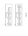
- FIG. 1 shows a known thin provisioning function to allocate areas randomly selected from several HDDs to a virtual volume.
- FIG. 2 shows a thin provisioning function to allocate areas selected from several HDDs to a virtual volume according to an embodiment of the present invention.
- FIG. 3 illustrates an example of a hardware configuration of an information system in which the method and apparatus of the invention may be applied.
- FIG. 4 illustrates an example of the memory in the application server and the memory in the storage subsystem of FIG. 3 according to a first embodiment of the invention.
- FIG. 5 shows an example of RAID group information according to the first embodiment.
- FIG. 6 shows an example of RAID information according to the first embodiment.
- FIG. 7 shows an example of logical volume information.
- FIG. 8 shows an example of pool information.
- FIG. 9 shows an example of virtual volume information.
- FIG. 10 shows an example of the read command and the write command.
- FIG. 11 shows an example of a diagram illustrating relationships between virtual volumes and logical volumes, between logical volumes and RAID groups, and between RAIDs group and HDDs.
- FIG. 12 shows an example of a flow diagram showing that the disk control program receives the read command or the write command from the application program and the disk control program sends the result of read or write.
- FIG. 13 is an example of a flow diagram showing that the page selection program selects a page and the disk control program allocates the page to a virtual volume in step 1004 of FIG. 12 .
- FIG. 14 illustrates an example of the memory in the application server and the memory in the storage subsystem of FIG. 3 according to a second embodiment of the invention.
- FIG. 15 shows an example of RAID group information according to the second embodiment.
- FIG. 16 shows an example of RAID information according to the second embodiment.
- FIG. 17 shows an example of performance information according to the second embodiment.
- FIG. 18 shows an example of a diagram illustrating calculation of a location according to the second embodiment.
- the present invention also relates to an apparatus for performing the operations herein.
- This apparatus may be specially constructed for the required purposes, or it may include one or more general-purpose computers selectively activated or reconfigured by one or more computer programs.
- Such computer programs may be stored in a computer-readable storage medium, such as, but not limited to optical disks, magnetic disks, read-only memories, random access memories, solid state devices and drives, or any other types of media suitable for storing electronic information.
- the algorithms and displays presented herein are not inherently related to any particular computer or other apparatus.
- Various general-purpose systems may be used with programs and modules in accordance with the teachings herein, or it may prove convenient to construct a more specialized apparatus to perform desired method steps.
- the present invention is not described with reference to any particular programming language.
- Exemplary embodiments of the invention provide apparatuses, methods and computer programs for the allocation of an area of a logical volume to a virtual volume.
- FIG. 3 illustrates an example of a hardware configuration of an information system in which the method and apparatus of the invention may be applied.
- the system comprises an application server 100, a SAN (Storage Area Network) 120, a LAN (Local Area Network) 140, and a storage subsystem 160.
- the application server 100 comprises a CPU (Central Processing Unit) 101, a memory 102, a HDD (Hard Disk Drive) 103, a SAN interface 104, and a LAN interface 105.
- the CPU 101 reads programs from the memory 102 and executes the programs.
- the memory 102 reads programs and data from the HDD 103 when the application server 100 starts and stores the programs and the data.
- the HDD 103 stores programs and data.
- the SAN interface 104 connects the application server 100 and the SAN 120.
- the LAN interface 105 connects the application server 100 and the LAN 140.
- the SAN 120 connects the application server 100 and the storage subsystem 160.
- the application server 100 uses the SAN 120 to send application data to the storage subsystem 160 and receive application data from the storage subsystem 160.
- the application server 100 uses the LAN 140 to send management data to the storage subsystem 160 and receive management data from the storage subsystem 160.
- the LAN 140 connects the application server 100 and the storage subsystem 160.
- the storage subsystem 160 comprises a SAN interface 161, a LAN interface 162, a CPU 163, a memory 164, a disk interface 165, a HDD 166, and a SSD (Solid State Drive) 167.
- the SAN interface 161 connects the storage subsystem 160 and the SAN 120.
- the LAN interface 162 connects the storage subsystem 160 and the LAN 140.
- the CPU 163 reads programs from the memory 164 and executes the programs.
- the memory 164 reads programs and data from the HDD 166 and the SSD 167 when the storage subsystem 160 starts and stores the programs and the data.
- the disk interface 165 connects the storage subsystem 160, the HDD 166, and the SSD 167.
- the HDD 166 stores programs and data.
- the SSD 167 stores programs and data.
- FIG. 4 illustrates an example of the memory 102 in the application server 100 and the memory 164 in the storage subsystem 160 of FIG. 1 according to the first embodiment.
- the memory 102 comprises an OS (Operating System) program 201 and an application program 202.
- the OS program 201 executes the application program 202.
- the application program 202 (e.g., database program) reads data from the storage subsystem 160, processes data, and writes the results to the storage subsystem 160.
- the memory 164 in the storage subsystem 160 comprises a disk control program 221, RAID (Redundant Arrays of Inexpensive (or Independent) Disks) group information 222, RAID information 223, logical volume information 224, pool information 225, virtual volume information 226, and a page selection program 227.
- the disk control program 221 receives a read command and a write command from the application server 100, reads data from the HDD 166 and the SSD 167, and writes data to the HDD 166 and the SSD 167 using the RAID group information 222, the RAID information 223, the logical volume information 224, the pool information 225, and the virtual volume information 226.
- FIG. 5 shows an example of RAID group information 222 according to the first embodiment.
- the RAID group information 222 includes columns of a RAID group name 301, a media name 302, a RAID level 303, a media type 304, and a capacity 305.
- the row 306 shows that "RG A” comprises “HDD A,” “HDD B,” “HDD C,” and “HDD D,” the RAID level of “RG A” is “RAID 5,” “RG A” comprises “HDD 15,000 rpm,” and the capacity of "RG A” is "100.”
- FIG. 6 shows an example of RAID information 223 according to the first embodiment.
- the RAID information 223 includes columns of a RAID group name 401, a page number 402, a location 403, a RAID group address 404, a data media name 405, a data media address 406, a parity media name 407, and a parity media address 408.
- the row 409 and the row 410 show that the address from “0" to “9” on “PAGE 200" on “RG A” is allocated to the address from “0” to “9” on “HDD A” and located on “0%” from the beginning of “RG A,” the address from “10” to “19” on “PAGE 200” on “RG A” is allocated to the address from “0” to “9” on “HDD B” and located on “0%” from the beginning of “RG A,” and the parity of "PAGE 200" on “RG A” is located on the address from “0” to “9” on “HDD C.”
- the page selection program 227 calculates the location 403 when the RAID information 223 is updated. For example, the address of "PAGE 201" on “RG A” is from “20” to “39” and the capacity 305 of "RG A” is “100.” Therefore the location 403 of "PAGE 201" is "20%” (20/100).
- FIG. 7 shows an example of the logical volume information 224 in the form of a table.
- the logical volume information 224 includes columns of a logical volume name 501, a logical volume address 502, a RAID group name 503, and a RAID group address 504.
- the row 505 shows that the address from “0" to "99” of "L-VOL A" is allocated to the address from "0" to "99” in "RG A.”
- FIG. 8 shows an example of the pool information 225 in the form of a table.
- the pool information 225 includes columns of a pool name 601, a logical volume name 602, a virtual volume name 603, and a capacity 604.
- the row 605 shows "POOL A” comprises “L-VOL A” and “L-VOL B,” the area of “POOL A” is used by “V-VOL A,” and the capacity of "V-VOL A” is "200.”
- FIG. 9 shows an example of the virtual volume information 226 in the form of a table.
- the virtual volume information 226 includes columns of a virtual volume name 701, a virtual volume address 702, a page number 703, a logical volume name 704, a logical volume address 705, and a page number 706.
- the row 707 shows that the address from “0" to "19" on “V-VOL A” is "PAGE 0,” the address from "0" to "19” on “L-VOL A” is "PAGE 100,” and "PAGE 0" is allocated to "PAGE 100.”
- FIG. 10 shows an example of the read command 800 and the write command 820.
- the read command 800 includes a command type 801, a volume name 802, and a volume address 803.
- the read command 800 is sent from the application program 202 to the storage subsystem 160.
- the write command 820 includes a command type 821, a volume name 822, a volume address 823, and data 824.
- the write command 820 is sent from the application program 202 to the storage subsystem 160.
- FIG. 11 shows an example of a diagram illustrating relationships between virtual volumes and logical volumes, between logical volumes and RAID groups, and between RAIDs group and HDDs.
- the address from “40" to “59” on “V-VOLA” is mapped to the address from “20" to "39” on “L-VOL A.”
- the address from “20” to “39” on “L-VOLA” is mapped to the address from “20" to "39” on “RG A.”
- the address from “20” to “29” on “RG A” is mapped to the address from "10” to "19” on “HDD A.”
- the address from “30” to "39” on “RG A” is mapped to the address from "10” to "19” on “HDD C.”
- FIG. 12 is an example of a flow diagram showing that the disk control program 221 receives the read command 800 or the write command 820 from the application program 202, and the disk control program 221 sends the result of read or write.
- the disk control program 221 receives the read command 800 or the write command 820 from the application program 202.
- decision step 1002 if the command that the disk control program 221 received in step 1001 is the write command 820, then the process goes to decision step 1003; if not, then the process goes to decision step 1006.
- step 1003 if an area specified by the volume name 822 and the volume address 823 of the write command 820 is allocated in the virtual volume information 226, then the process goes to step 1005; if not, then the process goes to step 1004.
- step 1004 the disk control program 221 allocates an unallocated area of a logical volume to the virtual volume specified by the volume name 822 and the volume address 823, and updates the virtual volume information 226.
- the disk control program 221 gets the volume name 822 and the volume address 823 from the write command 820, gets the logical volume name 704 and the logical volume address 705 from the virtual volume information 226, gets the RAID group name 503 and the RAID group address 504 from the logical volume information 224, gets the data media name 405 and the data media address 406 from the RAID information 223, gets the parity media name 407 and the parity media address 408 from the RAID information 223, reads an area specified by the data media name 405 and the data media address 406, calculates a parity and writes the data 824 of the write command 820 to an area specified by the data media name 405 and the data media address 406, and writes the parity to an area specified by the parity media name 407 and the parity media address 408.
- the volume name 822 is "V-VOL A” and the volume address 823 is an address from “40" to "43”
- the data 824 is written to an address from “10” to "13” on “HDD A”
- the disk control program 221 reads an address from “10” to “19” on “HDD A” and an address from “10” to “19” on “HDD C”
- calculates a parity and writes the parity to an address from "10” to "19” on “HDD B.”
- step 1006 if an area specified by the volume name 802 and the volume address 803 of the read command 800 is allocated in the virtual volume information 226, then the process goes to step 1008; if not, then the process goes to step 1007.
- step 1007 the disk control program 221 returns "0" to the application server 100 because the area specified by the volume name 802 and the volume address 803 is not written.
- the disk control program 221 gets the volume name 802 and the volume address 803 from the read command 800, gets the logical volume name 704 and the logical volume address 705 from the virtual volume information 226, gets the RAID group name 503 and the RAID group address 504 from the logical volume information 224, gets the data media name 405 and the data media address 406 from the RAID information 223, reads an area specified by the data media name 405 and the data media address 406, and returns the data.
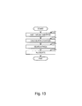
- FIG. 13 is an example of a flow diagram showing that the page selection program 227 selects a page and the disk control program 221 allocates the page to a virtual volume in step 1004 of FIG. 12 .
- the page selection program 227 gets a target address from the volume name 822 and the volume address 823 of the write command 820.
- step 1103 the page selection program 227 selects a near page which is nearest to the location calculated in step 1102 from the RAID information 223. For example, the page selection program 227 calculated the location and the location was “20%.” Therefore the page selection program 227 selects "PAGE 201" where the location 403 of the RAID information 223 is "20%.”
- step 1104 the disk control program 221 allocates the address from “20" to "39” on the "L-VOL A" to the address specified by the volume name 822 and the volume address 823 because the address of the page selected in step 1103 is from "20" to "39” on the "RG A” from the logical volume information 224.
- FIG. 14 illustrates an example of the memory 102 in the application server 100 and the memory 164 in the storage subsystem 160 of FIG. 3 according to the second embodiment.
- the memory 164 comprises a disk control program 221, RAID group information 222, RAID information 223, logical volume information 224, pool information 225, virtual volume information 226, a page selection program 227, and performance information 228.
- the performance information 228 is not provided in the first embodiment of FIG. 4 .
- FIG. 15 shows an example of RAID group information 222 according to the second embodiment. Unlike the RAID group information of the first embodiment ( FIG. 5 ), there are several media types in the second embodiment.
- FIG. 16 shows an example of RAID information 223 according to the second embodiment. Unlike the RAID information of the first embodiment ( FIG. 6 ), there are several media types in the second embodiment.
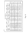
- FIG. 17 shows an example of performance information 228 according to the second embodiment.
- the performance information 228 includes columns of a rank 1501 and a media name 1502. For example, the row 1503 shows that "SSD MLC" is the highest performance media.
- FIG. 18 shows an example of a diagram illustrating calculation of a location according to the second embodiment.
- the highest performance media type is "SSD MLC” according to the performance information 228 and the capacity is "100" according to the RAID group information 222 in FIG. 15 .
- the second highest performance media type is "HDD 15,000rpm” according to the performance information 228 and the capacity is "200” according to the RAID group information 222 in FIG. 15 .
- the third highest performance media type is "HDD 10,000 rpm" according to the performance information 228 and the capacity is "100” according to the RAID group information 222 in FIG. 15 .
- the location 403 of "PAGE 501" is "35%” (100 + 20 * 2/400).
- the page selection program 227 calculates the location 403 when the RAID information 223 is updated.
- the system configuration illustrated in FIG. 3 is purely exemplary of information systems in which the present invention may be implemented, and the invention is not limited to a particular hardware configuration.
- the computers and storage systems implementing the invention can also have known I/O devices (e.g., CD and DVD drives, floppy disk drives, hard drives, etc.) which can store and read the modules, programs and data structures used to implement the above-described invention.
- These modules, programs and data structures can be encoded on such computer-readable media.
- the data structures of the invention can be stored on computer-readable media independently of one or more computer-readable media on which reside the programs used in the invention.
- the components of the system can be interconnected by any form or medium of digital data communication, e.g., a communication network. Examples of communication networks include local area networks, wide area networks, e.g., the Internet, wireless networks, storage area networks, and the like.
- the operations described above can be performed by hardware, software, or some combination of software and hardware.
- Various aspects of embodiments of the invention may be implemented using circuits and logic devices (hardware), while other aspects may be implemented using instructions stored on a machine-readable medium (software), which if executed by a processor, would cause the processor to perform a method to carry out embodiments of the invention.
- some embodiments of the invention may be performed solely in hardware, whereas other embodiments may be performed solely in software.
- the various functions described can be performed in a single unit, or can be spread across a number of components in any number of ways.
- the methods may be executed by a processor, such as a general purpose computer, based on instructions stored on a computer-readable medium. If desired, the instructions can be stored on the medium in a compressed and/or encrypted format.
Abstract
A storage system comprises a plurality of hard disk drives and a storage controller providing a plurality of virtual volumes to a server and including a processor and a memory. The storage controller allocates pages of the plurality of virtual volumes to the plurality of hard disk drives in response to write requests. The storage controller controls to allocate outer sections of the plurality of hard disks to first addresses of the virtual volume and allocates inner sections of the plurality of hard disk drives to second addresses of the virtual volume, wherein the first addresses are lower than the second addresses.
Description
- The present invention relates generally to storage systems with thin provisioning and, more particularly, to the allocation of an area of a logical volume to a virtual volume.
- A HDD (Hard Disk Drive) has a platter to store magnetic data. There are a lot of sectors on the platter. The HDD also has a disk head to read the data from the sector and write the data from the sector. The length of the sector is fixed. The number of sectors on the outer circumference of the platter is more than that on the inner circumference because the length of the outer circumference on the platter is greater than the length of the inner circumference. Therefore, a read time from the outer circumference and a write time to the outer circumference are shorter than those for the inner circumference.
- The HDD is accessed with an address to specify the area to read or write. A lower address is allocated to the outer circumference and a higher address is allocated to the inner circumference. Therefore a read time from a lower address and a write time to a lower address are shorter than those for a higher address. There is an application to store data that is frequently accessed to the lower address and to store data that is rarely accessed to the higher address in order to complete read and write processes more quickly.
- In recent years, thin provisioning has become popular. Thin provisioning is a method for allocating an area to a virtual volume when a storage subsystem receives a write command to an unallocated area. Existing methods allow a thin provisioning function to allocate an area randomly selected from several HDDs to a virtual volume (see
FIG. 1 ). When an area on a higher address is allocated to a lower address in the virtual volume, the application stores data that is frequently accessed to the higher address in HDD. As a result, performance in the application will decrease. An example for managing virtual volumes in a utility storage server system is found inU.S. Patent No. 6,823,442 . - Exemplary embodiments of the invention provide a technique for allocation of an area of a logical volume to a virtual volume for improved performance. In specific embodiments, a page selection program gets a target address, calculates a location in the virtual volume, and searches a near page which is nearest to the calculated location and disk control program allocates the page to the virtual volume when a storage system receives a write command to unallocated area on a virtual volume. In one embodiment, the page selection program calculates locations of pages of RAID groups based on an address of the pages previously. In another embodiment, the page selection program calculates locations of pages of RAID groups based on an address of the pages and media performance previously. In this way, an area in lower address is allocated to lower address in the virtual volume and application performance does not decrease.
- In accordance with an aspect of the present invention, a storage system comprises a plurality of hard disk drives and a storage controller providing a plurality of virtual volumes to a server and including a processor and a memory. The storage controller allocates pages of the plurality of virtual volumes to the plurality of hard disk drives in response to write requests, and the storage controller controls to allocate outer sections of the plurality of hard disks to first addresses of the virtual volume and allocates inner sections of the plurality of hard disk drives to second addresses of the virtual volume, wherein the first addresses are lower than the second addresses.
- In some embodiments, the plurality of hard disk drives may be allocated to a plurality of logical volumes. The storage controller may map first addresses of the plurality of hard disk drives to be allocated to first addresses of the plurality of logical volumes and may map second addresses of the plurality of hard disk drives to be allocated to second addresses of the plurality of logical volumes, the first addresses of the plurality of hard disk drives may be relatively smaller than the second addresses of the plurality of hard disk drives, the first addresses of the plurality of logical volumes may be relatively smaller than the second addresses of the plurality of logical volumes. In response to a write request, targeted page of a virtual volume according to the write request may be allocated to a page of the plurality of logical volumes, wherein the page of the plurality of logical volumes to be allocated may be selected based on the address of the virtual volume. The page of the plurality of logical volumes to be allocated may be selected so that an unallocated page closest to a proportionate location of the plurality of logical volumes against the proportionate location of the virtual volume for the targeted page is selected.
- In accordance with another aspect of the invention, there may be provided a storage system coupled to a server via a network comprises: a processor; a memory; a page selection module being configured to obtain a target address of a virtual volume for data of a write request, wherein the target address is unallocated; calculate a location in the virtual volume based on the target address; and search a near page which is nearest to a corresponding location in the logical volume; and a disk control module being configured to allocate the near page in the logical volume to the unallocated target address of the virtual volume. The logical volume is allocated to the virtual volume so as to allocate lower addresses of the logical volume to lower addresses of the virtual volume and to allocate higher addresses the logical volume to higher addresses of the virtual volume.
- In some embodiments, the logical volume may be mapped to a plurality of hard disk drives each with outer sections of the plurality of hard disk drives having lower addresses of the logical volume than inner sections of the plurality of hard disk drives. In response to a write request from an application in the server, the disk control module may allocate a first address of the virtual volume which corresponds to a first section of a hard disk drive for writing a first data of the write request and may allocate a second address of the virtual volume which corresponds to a second section of the hard disk drive for writing a second data of the write request, the first data being preferably accessed more frequently than the second data, the first address being preferably a lower address than the second address. The logical volume is preferably mapped to a RAID group and the RAID group is preferably mapped to a plurality of hard disk drives in a manner to allocate a section at a higher circumference to a lower address of the virtual volume than a section at a lower circumference.
- In specific embodiments, the logical volume is preferably mapped to different types of storage media having different performance levels, a higher performance media having preferably lower addresses of the logical volume than a lower performance media. The logical volume is preferably allocated to virtual volume so as to allocate higher performance media to lower addresses of the virtual volume and to allocate lower performance media to higher addresses of the virtual volume. The target address of the virtual volume preferably comprises a virtual volume name identifying the virtual volume and a virtual volume address in the virtual volume. Calculating a location in the virtual volume based on the target address preferably comprises calculating a location percentage which is equal to the virtual address divided by a capacity of the virtual volume identified by the virtual volume name. The location percentage is preferably used to find the near page in the logical volume.
- Another aspect of this invention is directed to an allocation method for a storage system having a plurality of hard disk drives. The allocation method comprises: providing a plurality of virtual volumes to a server; and allocating pages of the plurality of virtual volumes to the plurality of hard disk drives in response to write requests from the server, including allocating outer sections of the plurality of hard disks to first addresses of the virtual volume and allocating inner sections of the plurality of hard disk drives to second addresses of the virtual volume, wherein the first addresses are lower than the second addresses.
- Another aspect of this invention is directed to an allocation method for a storage system coupled to a server via a network. The allocation method comprises: obtaining a target address of a virtual volume for data of a write request, wherein the target address is unallocated; calculating a location in the virtual volume based on the target address; searching a near page which is nearest to a corresponding location in the logical volume; and allocating the near page in the logical volume to the unallocated target address of the virtual volume. The logical volume is allocated to the virtual volume so as to allocate lower addresses of the logical volume to lower addresses of the virtual l volume and to allocate higher addresses the logical volume to higher addresses of the virtual volume.
According to preferred embodiments, the method may further comprise: mapping the logical volume to a plurality of hard disk drives each with outer sections of the plurality of hard disk drives having lower addresses of the logical volume than inner sections of the plurality of hard disk drives.
According to preferred embodiments, the method may further comprise: in response to a write request from an application in the server, allocating a first address of the virtual volume which corresponds to a first section of a hard disk drive for writing a first data of the write request and/or allocating a second address of the virtual volume which corresponds to a second section of the hard disk drive for writing a second data of the write request, the first data being preferably accessed more frequently than the second data, the first address being a lower address than the second address.
Preferably, the logical volume is mapped to a RAID group and the RAID group is preferably mapped to a plurality of hard disk drives in a manner to allocate a section at a higher circumference to a lower address of the virtual volume than a section at a lower circumference.
According to preferred embodiments, the method may further comprise: mapping the logical volume to different types of storage media having different performance levels, a higher performance media having lower addresses of the logical volume than a lower performance media; wherein the logical volume is preferably allocated to the virtual volume so as to allocate higher performance media to lower addresses of the virtual volume and to allocate lower performance media to higher addresses of the virtual volume.
Preferably, the target address of the virtual volume comprises a virtual volume name identifying the virtual volume and a virtual volume address in the virtual volume.
Preferably, calculating a location in the virtual volume based on the target address comprises calculating a location percentage which is equal to the virtual address divided by a capacity of the virtual volume identified by the virtual volume name; wherein the location percentage is preferably used to find the near page in the logical volume. - These and other features and advantages of the present invention will become apparent to those of ordinary skill in the art in view of the following detailed description of the specific embodiments.
-
FIG. 1 shows a known thin provisioning function to allocate areas randomly selected from several HDDs to a virtual volume. -
FIG. 2 shows a thin provisioning function to allocate areas selected from several HDDs to a virtual volume according to an embodiment of the present invention. -
FIG. 3 illustrates an example of a hardware configuration of an information system in which the method and apparatus of the invention may be applied. -
FIG. 4 illustrates an example of the memory in the application server and the memory in the storage subsystem ofFIG. 3 according to a first embodiment of the invention. -
FIG. 5 shows an example of RAID group information according to the first embodiment. -
FIG. 6 shows an example of RAID information according to the first embodiment. -
FIG. 7 shows an example of logical volume information. -
FIG. 8 shows an example of pool information. -
FIG. 9 shows an example of virtual volume information. -
FIG. 10 shows an example of the read command and the write command. -
FIG. 11 shows an example of a diagram illustrating relationships between virtual volumes and logical volumes, between logical volumes and RAID groups, and between RAIDs group and HDDs. -
FIG. 12 shows an example of a flow diagram showing that the disk control program receives the read command or the write command from the application program and the disk control program sends the result of read or write. -
FIG. 13 is an example of a flow diagram showing that the page selection program selects a page and the disk control program allocates the page to a virtual volume instep 1004 ofFIG. 12 . -
FIG. 14 illustrates an example of the memory in the application server and the memory in the storage subsystem ofFIG. 3 according to a second embodiment of the invention. -
FIG. 15 shows an example of RAID group information according to the second embodiment. -
FIG. 16 shows an example of RAID information according to the second embodiment. -
FIG. 17 shows an example of performance information according to the second embodiment. -
FIG. 18 shows an example of a diagram illustrating calculation of a location according to the second embodiment. - In the following detailed description of the invention, reference is made to the accompanying drawings which form a part of the disclosure, and in which are shown by way of illustration, and not of limitation, exemplary embodiments by which the invention may be practiced. In the drawings, like numerals describe substantially similar components throughout the several views. Further, it should be noted that while the detailed description provides various exemplary embodiments, as described below and as illustrated in the drawings, the present invention is not limited to the embodiments described and illustrated herein, but can extend to other embodiments, as would be known or as would become known to those skilled in the art. Reference in the specification to "one embodiment," "this embodiment," or "these embodiments" means that a particular feature, structure, or characteristic described in connection with the embodiment is included in at least one embodiment of the invention, and the appearances of these phrases in various places in the specification are not necessarily all referring to the same embodiment. Additionally, in the following detailed description, numerous specific details are set forth in order to provide a thorough understanding of the present invention. However, it will be apparent to one of ordinary skill in the art that these specific details may not all be needed to practice the present invention. In other circumstances, well-known structures, materials, circuits, processes and interfaces have not been described in detail, and/or may be illustrated in block diagram form, so as to not unnecessarily obscure the present invention.
- Furthermore, some portions of the detailed description that follow are presented in terms of algorithms and symbolic representations of operations within a computer. These algorithmic descriptions and symbolic representations are the means used by those skilled in the data processing arts to most effectively convey the essence of their innovations to others skilled in the art. An algorithm is a series of defined steps leading to a desired end state or result. In the present invention, the steps carried out require physical manipulations of tangible quantities for achieving a tangible result. Usually, though not necessarily, these quantities take the form of electrical or magnetic signals or instructions capable of being stored, transferred, combined, compared, and otherwise manipulated. It has proven convenient at times, principally for reasons of common usage, to refer to these signals as bits, values, elements, symbols, characters, terms, numbers, instructions, or the like. It should be borne in mind, however, that all of these and similar terms are to be associated with the appropriate physical quantities and are merely convenient labels applied to these quantities. Unless specifically stated otherwise, as apparent from the following discussion, it is appreciated that throughout the description, discussions utilizing terms such as "processing," "computing," "calculating," "determining," "displaying," or the like, can include the actions and processes of a computer system or other information processing device that manipulates and transforms data represented as physical (electronic) quantities within the computer system's registers and memories into other data similarly represented as physical quantities within the computer system's memories or registers or other information storage, transmission or display devices.
- The present invention also relates to an apparatus for performing the operations herein. This apparatus may be specially constructed for the required purposes, or it may include one or more general-purpose computers selectively activated or reconfigured by one or more computer programs. Such computer programs may be stored in a computer-readable storage medium, such as, but not limited to optical disks, magnetic disks, read-only memories, random access memories, solid state devices and drives, or any other types of media suitable for storing electronic information. The algorithms and displays presented herein are not inherently related to any particular computer or other apparatus. Various general-purpose systems may be used with programs and modules in accordance with the teachings herein, or it may prove convenient to construct a more specialized apparatus to perform desired method steps. In addition, the present invention is not described with reference to any particular programming language. It will be appreciated that a variety of programming languages may be used to implement the teachings of the invention as described herein. The instructions of the programming language(s) may be executed by one or more processing devices, e.g., central processing units (CPUs), processors, or controllers.
- Exemplary embodiments of the invention, as will be described in greater detail below, provide apparatuses, methods and computer programs for the allocation of an area of a logical volume to a virtual volume.
- First Embodiment: Volume pool having only one media type
- A. System Configuration
-
FIG. 3 illustrates an example of a hardware configuration of an information system in which the method and apparatus of the invention may be applied. The system comprises anapplication server 100, a SAN (Storage Area Network) 120, a LAN (Local Area Network) 140, and a storage subsystem 160. Theapplication server 100 comprises a CPU (Central Processing Unit) 101, amemory 102, a HDD (Hard Disk Drive) 103, aSAN interface 104, and aLAN interface 105. TheCPU 101 reads programs from thememory 102 and executes the programs. Thememory 102 reads programs and data from theHDD 103 when theapplication server 100 starts and stores the programs and the data. TheHDD 103 stores programs and data. TheSAN interface 104 connects theapplication server 100 and theSAN 120. TheLAN interface 105 connects theapplication server 100 and theLAN 140. TheSAN 120 connects theapplication server 100 and the storage subsystem 160. Theapplication server 100 uses theSAN 120 to send application data to the storage subsystem 160 and receive application data from the storage subsystem 160. Theapplication server 100 uses theLAN 140 to send management data to the storage subsystem 160 and receive management data from the storage subsystem 160. TheLAN 140 connects theapplication server 100 and the storage subsystem 160. The storage subsystem 160 comprises aSAN interface 161, aLAN interface 162, a CPU 163, amemory 164, adisk interface 165, aHDD 166, and a SSD (Solid State Drive) 167. TheSAN interface 161 connects the storage subsystem 160 and theSAN 120. TheLAN interface 162 connects the storage subsystem 160 and theLAN 140. The CPU 163 reads programs from thememory 164 and executes the programs. Thememory 164 reads programs and data from theHDD 166 and theSSD 167 when the storage subsystem 160 starts and stores the programs and the data. Thedisk interface 165 connects the storage subsystem 160, theHDD 166, and theSSD 167. TheHDD 166 stores programs and data. TheSSD 167 stores programs and data. -
FIG. 4 illustrates an example of thememory 102 in theapplication server 100 and thememory 164 in the storage subsystem 160 ofFIG. 1 according to the first embodiment. Thememory 102 comprises an OS (Operating System)program 201 and anapplication program 202. TheOS program 201 executes theapplication program 202. The application program 202 (e.g., database program) reads data from the storage subsystem 160, processes data, and writes the results to the storage subsystem 160. - The
memory 164 in the storage subsystem 160 comprises adisk control program 221, RAID (Redundant Arrays of Inexpensive (or Independent) Disks)group information 222,RAID information 223, logical volume information 224,pool information 225, virtual volume information 226, and a page selection program 227. Thedisk control program 221 receives a read command and a write command from theapplication server 100, reads data from theHDD 166 and theSSD 167, and writes data to theHDD 166 and theSSD 167 using theRAID group information 222, theRAID information 223, the logical volume information 224, thepool information 225, and the virtual volume information 226. -
FIG. 5 shows an example ofRAID group information 222 according to the first embodiment. TheRAID group information 222 includes columns of aRAID group name 301, amedia name 302, aRAID level 303, amedia type 304, and acapacity 305. For example, the row 306 shows that "RG A" comprises "HDD A," "HDD B," "HDD C," and "HDD D," the RAID level of "RG A" is "RAID 5," "RG A" comprises "HDD 15,000 rpm," and the capacity of "RG A" is "100." There is only one media type in the first embodiment. -
FIG. 6 shows an example ofRAID information 223 according to the first embodiment. TheRAID information 223 includes columns of aRAID group name 401, apage number 402, alocation 403, aRAID group address 404, adata media name 405, adata media address 406, aparity media name 407, and aparity media address 408. For example, the row 409 and the row 410 show that the address from "0" to "9" on "PAGE 200" on "RG A" is allocated to the address from "0" to "9" on "HDD A" and located on "0%" from the beginning of "RG A," the address from "10" to "19" on "PAGE 200" on "RG A" is allocated to the address from "0" to "9" on "HDD B" and located on "0%" from the beginning of "RG A," and the parity of "PAGE 200" on "RG A" is located on the address from "0" to "9" on "HDD C." - The page selection program 227 calculates the
location 403 when theRAID information 223 is updated. For example, the address of "PAGE 201" on "RG A" is from "20" to "39" and thecapacity 305 of "RG A" is "100." Therefore thelocation 403 of "PAGE 201" is "20%" (20/100). -
FIG. 7 shows an example of the logical volume information 224 in the form of a table. The logical volume information 224 includes columns of alogical volume name 501, alogical volume address 502, a RAID group name 503, and aRAID group address 504. For example, the row 505 shows that the address from "0" to "99" of "L-VOL A" is allocated to the address from "0" to "99" in "RG A." -
FIG. 8 shows an example of thepool information 225 in the form of a table. Thepool information 225 includes columns of apool name 601, a logical volume name 602, avirtual volume name 603, and acapacity 604. For example, the row 605 shows "POOL A" comprises "L-VOL A" and "L-VOL B," the area of "POOL A" is used by "V-VOL A," and the capacity of "V-VOL A" is "200." -
FIG. 9 shows an example of the virtual volume information 226 in the form of a table. The virtual volume information 226 includes columns of a virtual volume name 701, avirtual volume address 702, a page number 703, a logical volume name 704, a logical volume address 705, and apage number 706. For example, the row 707 shows that the address from "0" to "19" on "V-VOL A" is "PAGE 0," the address from "0" to "19" on "L-VOL A" is "PAGE 100," and "PAGE 0" is allocated to "PAGE 100." -
FIG. 10 shows an example of the read command 800 and the write command 820. The read command 800 includes acommand type 801, avolume name 802, and avolume address 803. The read command 800 is sent from theapplication program 202 to the storage subsystem 160. The write command 820 includes a command type 821, a volume name 822, a volume address 823, and data 824. The write command 820 is sent from theapplication program 202 to the storage subsystem 160. -
FIG. 11 shows an example of a diagram illustrating relationships between virtual volumes and logical volumes, between logical volumes and RAID groups, and between RAIDs group and HDDs. For example, the address from "40" to "59" on "V-VOLA" is mapped to the address from "20" to "39" on "L-VOL A." The address from "20" to "39" on "L-VOLA" is mapped to the address from "20" to "39" on "RG A." The address from "20" to "29" on "RG A" is mapped to the address from "10" to "19" on "HDD A." The address from "30" to "39" on "RG A" is mapped to the address from "10" to "19" on "HDD C." - B. Process Flows
-
FIG. 12 is an example of a flow diagram showing that thedisk control program 221 receives the read command 800 or the write command 820 from theapplication program 202, and thedisk control program 221 sends the result of read or write. In step 1001, thedisk control program 221 receives the read command 800 or the write command 820 from theapplication program 202. Indecision step 1002, if the command that thedisk control program 221 received in step 1001 is the write command 820, then the process goes todecision step 1003; if not, then the process goes todecision step 1006. - In
decision step 1003, if an area specified by the volume name 822 and the volume address 823 of the write command 820 is allocated in the virtual volume information 226, then the process goes to step 1005; if not, then the process goes to step 1004. Instep 1004, thedisk control program 221 allocates an unallocated area of a logical volume to the virtual volume specified by the volume name 822 and the volume address 823, and updates the virtual volume information 226. - In
step 1005, thedisk control program 221 gets the volume name 822 and the volume address 823 from the write command 820, gets the logical volume name 704 and the logical volume address 705 from the virtual volume information 226, gets the RAID group name 503 and theRAID group address 504 from the logical volume information 224, gets thedata media name 405 and the data media address 406 from theRAID information 223, gets theparity media name 407 and the parity media address 408 from theRAID information 223, reads an area specified by thedata media name 405 and thedata media address 406, calculates a parity and writes the data 824 of the write command 820 to an area specified by thedata media name 405 and thedata media address 406, and writes the parity to an area specified by theparity media name 407 and theparity media address 408. For example, when the volume name 822 is "V-VOL A" and the volume address 823 is an address from "40" to "43", the data 824 is written to an address from "10" to "13" on "HDD A," thedisk control program 221 reads an address from "10" to "19" on "HDD A" and an address from "10" to "19" on "HDD C," calculates a parity, and writes the parity to an address from "10" to "19" on "HDD B." - In
decision step 1006, if an area specified by thevolume name 802 and thevolume address 803 of the read command 800 is allocated in the virtual volume information 226, then the process goes to step 1008; if not, then the process goes to step 1007. In step 1007, thedisk control program 221 returns "0" to theapplication server 100 because the area specified by thevolume name 802 and thevolume address 803 is not written. Instep 1008, thedisk control program 221 gets thevolume name 802 and thevolume address 803 from the read command 800, gets the logical volume name 704 and the logical volume address 705 from the virtual volume information 226, gets the RAID group name 503 and theRAID group address 504 from the logical volume information 224, gets thedata media name 405 and the data media address 406 from theRAID information 223, reads an area specified by thedata media name 405 and thedata media address 406, and returns the data. -
FIG. 13 is an example of a flow diagram showing that the page selection program 227 selects a page and thedisk control program 221 allocates the page to a virtual volume instep 1004 ofFIG. 12 . In step 1101, the page selection program 227 gets a target address from the volume name 822 and the volume address 823 of the write command 820. Instep 1102, the page selection program 227 calculates a location in the target virtual volume based on the volume name 822 and the volume address 823. For example, when the volume name 822 is "V-VOL A," the volume address 823 is from "40" to "43," and thecapacity 604 of "V-VOL A" is "200," the location in the "V-VOL A" is "20%" (= 40/200). In step 1103, the page selection program 227 selects a near page which is nearest to the location calculated instep 1102 from theRAID information 223. For example, the page selection program 227 calculated the location and the location was "20%." Therefore the page selection program 227 selects "PAGE 201" where thelocation 403 of theRAID information 223 is "20%." In step 1104, thedisk control program 221 allocates the address from "20" to "39" on the "L-VOL A" to the address specified by the volume name 822 and the volume address 823 because the address of the page selected in step 1103 is from "20" to "39" on the "RG A" from the logical volume information 224. - Second Embodiment: Volume pool having several media types
- The following describes only differences between the second embodiment and the first embodiment.
- A. System Configuration
-
FIG. 14 illustrates an example of thememory 102 in theapplication server 100 and thememory 164 in the storage subsystem 160 ofFIG. 3 according to the second embodiment. Thememory 164 comprises adisk control program 221,RAID group information 222,RAID information 223, logical volume information 224,pool information 225, virtual volume information 226, a page selection program 227, andperformance information 228. Theperformance information 228 is not provided in the first embodiment ofFIG. 4 . -
FIG. 15 shows an example ofRAID group information 222 according to the second embodiment. Unlike the RAID group information of the first embodiment (FIG. 5 ), there are several media types in the second embodiment. -
FIG. 16 shows an example ofRAID information 223 according to the second embodiment. Unlike the RAID information of the first embodiment (FIG. 6 ), there are several media types in the second embodiment. -
FIG. 17 shows an example ofperformance information 228 according to the second embodiment. Theperformance information 228 includes columns of a rank 1501 and a media name 1502. For example, the row 1503 shows that "SSD MLC" is the highest performance media. -
FIG. 18 shows an example of a diagram illustrating calculation of a location according to the second embodiment. There are three media types in theRAID group information 222 inFIG. 15 . The highest performance media type is "SSD MLC" according to theperformance information 228 and the capacity is "100" according to theRAID group information 222 inFIG. 15 . The second highest performance media type is "HDD 15,000rpm" according to theperformance information 228 and the capacity is "200" according to theRAID group information 222 inFIG. 15 . The third highest performance media type is "HDD 10,000 rpm" according to theperformance information 228 and the capacity is "100" according to theRAID group information 222 inFIG. 15 . Therefore, for example, the address of "PAGE 501" on "RG B" is from "20" to "39" and the sum ofcapacity 305 inFIG. 15 is "400" (= 100 + 100 + 100 + 100). Thelocation 403 of "PAGE 501" is "35%" (100 + 20 * 2/400). The page selection program 227 calculates thelocation 403 when theRAID information 223 is updated. - Of course, the system configuration illustrated in
FIG. 3 is purely exemplary of information systems in which the present invention may be implemented, and the invention is not limited to a particular hardware configuration. The computers and storage systems implementing the invention can also have known I/O devices (e.g., CD and DVD drives, floppy disk drives, hard drives, etc.) which can store and read the modules, programs and data structures used to implement the above-described invention. These modules, programs and data structures can be encoded on such computer-readable media. For example, the data structures of the invention can be stored on computer-readable media independently of one or more computer-readable media on which reside the programs used in the invention. The components of the system can be interconnected by any form or medium of digital data communication, e.g., a communication network. Examples of communication networks include local area networks, wide area networks, e.g., the Internet, wireless networks, storage area networks, and the like. - In the description, numerous details are set forth for purposes of explanation in order to provide a thorough understanding of the present invention. However, it will be apparent to one skilled in the art that not all of these specific details are required in order to practice the present invention. It is also noted that the invention may be described as a process, which is usually depicted as a flowchart, a flow diagram, a structure diagram, or a block diagram. Although a flowchart may describe the operations as a sequential process, many of the operations can be performed in parallel or concurrently. In addition, the order of the operations may be re-arranged.
- As is known in the art, the operations described above can be performed by hardware, software, or some combination of software and hardware. Various aspects of embodiments of the invention may be implemented using circuits and logic devices (hardware), while other aspects may be implemented using instructions stored on a machine-readable medium (software), which if executed by a processor, would cause the processor to perform a method to carry out embodiments of the invention. Furthermore, some embodiments of the invention may be performed solely in hardware, whereas other embodiments may be performed solely in software. Moreover, the various functions described can be performed in a single unit, or can be spread across a number of components in any number of ways. When performed by software, the methods may be executed by a processor, such as a general purpose computer, based on instructions stored on a computer-readable medium. If desired, the instructions can be stored on the medium in a compressed and/or encrypted format.
- From the foregoing, it will be apparent that the invention provides methods, apparatuses and programs stored on computer readable media for the allocation of an area of a logical volume to a virtual volume. Additionally, while specific embodiments have been illustrated and described in this specification, those of ordinary skill in the art appreciate that any arrangement that is calculated to achieve the same purpose may be substituted for the specific embodiments disclosed. This disclosure is intended to cover any and all adaptations or variations of the present invention, and it is to be understood that the terms used in the following claims should not be construed to limit the invention to the specific embodiments disclosed in the specification. Rather, the scope of the invention is to be determined entirely by the following claims, which are to be construed in accordance with the established doctrines of claim interpretation, along with the full range of equivalents to which such claims are entitled.
Claims (15)
- A storage system comprising:a plurality of hard disk drives; anda storage controller providing a plurality of virtual volumes to a server and including a processor and a memory;wherein the storage controller allocates pages of the plurality of virtual volumes to the plurality of hard disk drives in response to write requests, and the storage controller controls to allocate outer sections of the plurality of hard disks to first addresses of the virtual volume and allocates inner sections of the plurality of hard disk drives to second addresses of the virtual volume, wherein the first addresses are lower than the second addresses.
- The storage system according to claim 1,
wherein the plurality of hard disk drives are allocated to a plurality of logical volumes,
wherein the storage controller maps first addresses of the plurality of hard disk drives to be allocated to first addresses of the plurality of logical volumes and maps second addresses of the plurality of hard disk drives to be allocated to second addresses of the plurality of logical volumes, the first addresses of the plurality of hard disk drives are relatively smaller than the second addresses of the plurality of hard disk drives, the first addresses of the plurality of logical volumes are relatively smaller than the second addresses of the plurality of logical volumes,
wherein in response to a write request, targeted page of a virtual volume according to the write request is allocated to a page of the plurality of logical volumes, wherein the page of the plurality of logical volumes to be allocated is selected based on the address of the virtual volume. - The storage system according to claim 2,
wherein the page of the plurality of logical volumes to be allocated is selected so that an unallocated page closest to a proportionate location of the plurality of logical volumes against the proportionate location of the virtual volume for the targeted page is selected. - A storage system configured to be coupled to a server via a network, the storage system comprising:a processor;a memory;a page selection module, the page selection module being configured to obtain a target address of a virtual volume for data of a write request, wherein the target address is unallocated; calculate a location in the virtual volume based on the target address; and search a near page which is nearest to a corresponding location in the logical volume; anda disk control module being configured to allocate the near page in the logical volume to the unallocated target address of the virtual volume;wherein the logical volume is allocated to the virtual volume so as to allocate lower addresses of the logical volume to lower addresses of the virtual volume and to allocate higher addresses the logical volume to higher addresses of the virtual volume.
- The storage system according to claim 4,
wherein the logical volume is mapped to a plurality of hard disk drives each with outer sections of the plurality of hard disk drives having lower addresses of the logical volume than inner sections of the plurality of hard disk drives. - The storage system according to claim 5,
wherein in response to a write request from an application in the server, the disk control module allocates a first address of the virtual volume which corresponds to a first section of a hard disk drive for writing a first data of the write request and allocates a second address of the virtual volume which corresponds to a second section of the hard disk drive for writing a second data of the write request, the first data being accessed more frequently than the second data, the first address being a lower address than the second address. - The storage system according to claim 5 or 6,
wherein the logical volume is mapped to a RAID group and the RAID group is mapped to a plurality of hard disk drives in a manner to allocate a section at a higher circumference to a lower address of the virtual volume than a section at a lower circumference. - The storage system according to at least one of claims 4 to 7,
wherein the logical volume is mapped to different types of storage media having different performance levels, a higher performance media having lower addresses of the logical volume than a lower performance media; and
wherein the logical volume is allocated to virtual volume so as to allocate higher performance media to lower addresses of the virtual volume and to allocate lower performance media to higher addresses of the virtual volume. - The storage system according to at least one of claims 4 to 8,
wherein the target address of the virtual volume comprises a virtual volume name identifying the virtual volume and a virtual volume address in the virtual volume. - The storage system according to claim 9,
wherein calculating a location in the virtual volume based on the target address comprises calculating a location percentage which is equal to the virtual address divided by a capacity of the virtual volume identified by the virtual volume name; and
wherein the location percentage is used to find the near page in the logical volume. - An allocation method for a storage system configured to be coupled to a server via a network, the allocation method comprising:obtaining a target address of a virtual volume for data of a write request, wherein the target address is unallocated;calculating a location in the virtual volume based on the target address;searching a near page which is nearest to a corresponding location in the logical volume; andallocating the near page in the logical volume to the unallocated target address of the virtual volume;wherein the logical volume is allocated to the virtual volume so as to allocate lower addresses of the logical volume to lower addresses of the virtual volume and to allocate higher addresses the logical volume to higher addresses of the virtual volume.
- The allocation method according to claim 11, further comprising:mapping the logical volume to a plurality of hard disk drives each with outer sections of the plurality of hard disk drives having lower addresses of the logical volume than inner sections of the plurality of hard disk drives.
- The allocation method according to claim 12, further comprising:in response to a write request from an application in the server, allocating a first address of the virtual volume which corresponds to a first section of a hard disk drive for writing a first data of the write request and allocating a second address of the virtual volume which corresponds to a second section of the hard disk drive for writing a second data of the write request, the first data being accessed more frequently than the second data, the first address being a lower address than the second address.
- The allocation method according to claim 12 or 13,
wherein the logical volume is mapped to a RAID group and the RAID group is mapped to a plurality of hard disk drives in a manner to allocate a section at a higher circumference to a lower address of the virtual volume than a section at a lower circumference. - The allocation method according to at least one of claims 11 to 14, further comprising:mapping the logical volume to different types of storage media having different performance levels, a higher performance media having lower addresses of the logical volume than a lower performance media; andwherein the logical volume is allocated to the virtual volume so as to allocate higher performance media to lower addresses of the virtual volume and to allocate lower performance media to higher addresses of the virtual volume.
Applications Claiming Priority (1)
| Application Number | Priority Date | Filing Date | Title |
|---|---|---|---|
| US13/072,862 US8683120B2 (en) | 2011-03-28 | 2011-03-28 | Method and apparatus to allocate area to virtual volume |
Publications (1)
| Publication Number | Publication Date |
|---|---|
| EP2506135A2 true EP2506135A2 (en) | 2012-10-03 |
Family
ID=45491277
Family Applications (1)
| Application Number | Title | Priority Date | Filing Date |
|---|---|---|---|
| EP11194917A Withdrawn EP2506135A2 (en) | 2011-03-28 | 2011-12-21 | Method and apparatus to allocate area to virtual volume |
Country Status (3)
| Country | Link |
|---|---|
| US (1) | US8683120B2 (en) |
| EP (1) | EP2506135A2 (en) |
| JP (1) | JP5567545B2 (en) |
Families Citing this family (7)
| Publication number | Priority date | Publication date | Assignee | Title |
|---|---|---|---|---|
| CN105988874B (en) | 2015-02-10 | 2020-08-28 | 阿里巴巴集团控股有限公司 | Resource processing method and device |
| WO2016139749A1 (en) * | 2015-03-03 | 2016-09-09 | 株式会社日立製作所 | Computer system and storage control method |
| US10007556B2 (en) | 2015-12-07 | 2018-06-26 | International Business Machines Corporation | Reducing utilization speed of disk storage based on rate of resource provisioning |
| US10579284B2 (en) * | 2017-06-02 | 2020-03-03 | International Business Machines Corporation | Filesystem enhancements for unified file and object access in an object storage cloud |
| CN113687793B (en) * | 2017-06-30 | 2024-03-15 | 伊姆西Ip控股有限责任公司 | Storage management method and system |
| US10852966B1 (en) * | 2017-10-18 | 2020-12-01 | EMC IP Holding Company, LLC | System and method for creating mapped RAID group during expansion of extent pool |
| US10852951B1 (en) * | 2017-10-18 | 2020-12-01 | EMC IP Holding Company, LLC | System and method for improving I/O performance by introducing extent pool level I/O credits and user I/O credits throttling on Mapped RAID |
Citations (1)
| Publication number | Priority date | Publication date | Assignee | Title |
|---|---|---|---|---|
| US6823442B1 (en) | 2003-05-12 | 2004-11-23 | 3Pardata, Inc. | Method of managing virtual volumes in a utility storage server system |
Family Cites Families (9)
| Publication number | Priority date | Publication date | Assignee | Title |
|---|---|---|---|---|
| US6216202B1 (en) * | 1998-06-30 | 2001-04-10 | Emc Corporation | Method and apparatus for managing virtual storage devices in a storage system |
| US6839802B2 (en) * | 2000-12-08 | 2005-01-04 | International Business Machines Corporation | Method, system, and program for writing files to zone formatted storage media to improve data transfer rates |
| JP4175788B2 (en) * | 2001-07-05 | 2008-11-05 | 株式会社日立製作所 | Volume controller |
| US7441096B2 (en) * | 2004-07-07 | 2008-10-21 | Hitachi, Ltd. | Hierarchical storage management system |
| JP4413899B2 (en) * | 2006-08-11 | 2010-02-10 | 株式会社東芝 | Disk array subsystem and program |
| US7949847B2 (en) * | 2006-11-29 | 2011-05-24 | Hitachi, Ltd. | Storage extent allocation method for thin provisioning storage |
| US8359444B2 (en) * | 2008-09-24 | 2013-01-22 | Hitachi, Ltd. | System and method for controlling automated page-based tier management in storage systems |
| JP2010097563A (en) * | 2008-10-20 | 2010-04-30 | Nec Corp | Network storage system, disk array device, host device, access control method, and data access method |
| JP2011048553A (en) * | 2009-08-26 | 2011-03-10 | Nec Corp | Storage device, actual capacity allocation method in the same, and actual capacity allocation program |
-
2011
- 2011-03-28 US US13/072,862 patent/US8683120B2/en not_active Expired - Fee Related
- 2011-12-07 JP JP2011267528A patent/JP5567545B2/en not_active Expired - Fee Related
- 2011-12-21 EP EP11194917A patent/EP2506135A2/en not_active Withdrawn
Patent Citations (1)
| Publication number | Priority date | Publication date | Assignee | Title |
|---|---|---|---|---|
| US6823442B1 (en) | 2003-05-12 | 2004-11-23 | 3Pardata, Inc. | Method of managing virtual volumes in a utility storage server system |
Also Published As
| Publication number | Publication date |
|---|---|
| US8683120B2 (en) | 2014-03-25 |
| JP2012208916A (en) | 2012-10-25 |
| JP5567545B2 (en) | 2014-08-06 |
| US20120254532A1 (en) | 2012-10-04 |
Similar Documents
| Publication | Publication Date | Title |
|---|---|---|
| US9092141B2 (en) | Method and apparatus to manage data location | |
| US8464003B2 (en) | Method and apparatus to manage object based tier | |
| US9229653B2 (en) | Write spike performance enhancement in hybrid storage systems | |
| US8127076B2 (en) | Method and system for placement of data on a storage device | |
| US8683120B2 (en) | Method and apparatus to allocate area to virtual volume | |
| US9710187B1 (en) | Managing data relocation in storage systems | |
| US9753668B2 (en) | Method and apparatus to manage tier information | |
| US9229870B1 (en) | Managing cache systems of storage systems | |
| US8402214B2 (en) | Dynamic page reallocation storage system management | |
| WO2011101909A1 (en) | Virtual volume control method and storage device | |
| US11402998B2 (en) | Re-placing data within a mapped-RAID environment comprising slices, storage stripes, RAID extents, device extents and storage devices | |
| CN110196687B (en) | Data reading and writing method and device and electronic equipment | |
| US10496278B1 (en) | Inline compression support using discrete sized containers for backing store | |
| US20110302386A1 (en) | Method and apparatus to manage special rearrangement in automated tier management | |
| US8504764B2 (en) | Method and apparatus to manage object-based tiers | |
| US8468303B2 (en) | Method and apparatus to allocate area to virtual volume based on object access type | |
| US9547450B2 (en) | Method and apparatus to change tiers | |
| US9547443B2 (en) | Method and apparatus to pin page based on server state | |
| US8943280B2 (en) | Method and apparatus to move page between tiers | |
| US11144445B1 (en) | Use of compression domains that are more granular than storage allocation units |
Legal Events
| Date | Code | Title | Description |
|---|---|---|---|
| PUAI | Public reference made under article 153(3) epc to a published international application that has entered the european phase |
Free format text: ORIGINAL CODE: 0009012 |
|
| 17P | Request for examination filed |
Effective date: 20120302 |
|
| AK | Designated contracting states |
Kind code of ref document: A2 Designated state(s): AL AT BE BG CH CY CZ DE DK EE ES FI FR GB GR HR HU IE IS IT LI LT LU LV MC MK MT NL NO PL PT RO RS SE SI SK SM TR |
|
| AX | Request for extension of the european patent |
Extension state: BA ME |
|
| STAA | Information on the status of an ep patent application or granted ep patent |
Free format text: STATUS: THE APPLICATION HAS BEEN WITHDRAWN |
|
| 18W | Application withdrawn |
Effective date: 20160601 |
|
| RIC1 | Information provided on ipc code assigned before grant |
Ipc: G06F 3/06 20060101AFI20160527BHEP |