EP2505960A1 - Checking positional accuracy of features - Google Patents
Checking positional accuracy of features Download PDFInfo
- Publication number
- EP2505960A1 EP2505960A1 EP12161423A EP12161423A EP2505960A1 EP 2505960 A1 EP2505960 A1 EP 2505960A1 EP 12161423 A EP12161423 A EP 12161423A EP 12161423 A EP12161423 A EP 12161423A EP 2505960 A1 EP2505960 A1 EP 2505960A1
- Authority
- EP
- European Patent Office
- Prior art keywords
- positions
- features
- component
- reference points
- nominal
- Prior art date
- Legal status (The legal status is an assumption and is not a legal conclusion. Google has not performed a legal analysis and makes no representation as to the accuracy of the status listed.)
- Granted
Links
- 238000000034 method Methods 0.000 claims description 27
- 230000009466 transformation Effects 0.000 claims description 6
- 238000013507 mapping Methods 0.000 claims description 4
- 238000013519 translation Methods 0.000 claims description 3
- 238000012545 processing Methods 0.000 claims description 2
- 238000003754 machining Methods 0.000 description 3
- 238000005259 measurement Methods 0.000 description 3
- 238000009499 grossing Methods 0.000 description 2
- 238000004088 simulation Methods 0.000 description 2
- 238000003491 array Methods 0.000 description 1
- 230000000694 effects Effects 0.000 description 1
- 238000007689 inspection Methods 0.000 description 1
- 239000002184 metal Substances 0.000 description 1
- 230000002093 peripheral effect Effects 0.000 description 1
- 230000001131 transforming effect Effects 0.000 description 1
Images

Classifications
-
- G—PHYSICS
- G01—MEASURING; TESTING
- G01B—MEASURING LENGTH, THICKNESS OR SIMILAR LINEAR DIMENSIONS; MEASURING ANGLES; MEASURING AREAS; MEASURING IRREGULARITIES OF SURFACES OR CONTOURS
- G01B21/00—Measuring arrangements or details thereof, where the measuring technique is not covered by the other groups of this subclass, unspecified or not relevant
- G01B21/20—Measuring arrangements or details thereof, where the measuring technique is not covered by the other groups of this subclass, unspecified or not relevant for measuring contours or curvatures, e.g. determining profile
-
- G—PHYSICS
- G01—MEASURING; TESTING
- G01B—MEASURING LENGTH, THICKNESS OR SIMILAR LINEAR DIMENSIONS; MEASURING ANGLES; MEASURING AREAS; MEASURING IRREGULARITIES OF SURFACES OR CONTOURS
- G01B5/00—Measuring arrangements characterised by the use of mechanical techniques
- G01B5/0011—Arrangements for eliminating or compensation of measuring errors due to temperature or weight
-
- G—PHYSICS
- G01—MEASURING; TESTING
- G01B—MEASURING LENGTH, THICKNESS OR SIMILAR LINEAR DIMENSIONS; MEASURING ANGLES; MEASURING AREAS; MEASURING IRREGULARITIES OF SURFACES OR CONTOURS
- G01B11/00—Measuring arrangements characterised by the use of optical techniques
- G01B11/002—Measuring arrangements characterised by the use of optical techniques for measuring two or more coordinates
- G01B11/005—Measuring arrangements characterised by the use of optical techniques for measuring two or more coordinates coordinate measuring machines
-
- G—PHYSICS
- G01—MEASURING; TESTING
- G01B—MEASURING LENGTH, THICKNESS OR SIMILAR LINEAR DIMENSIONS; MEASURING ANGLES; MEASURING AREAS; MEASURING IRREGULARITIES OF SURFACES OR CONTOURS
- G01B11/00—Measuring arrangements characterised by the use of optical techniques
- G01B11/24—Measuring arrangements characterised by the use of optical techniques for measuring contours or curvatures
- G01B11/2408—Measuring arrangements characterised by the use of optical techniques for measuring contours or curvatures for measuring roundness
-
- G—PHYSICS
- G01—MEASURING; TESTING
- G01B—MEASURING LENGTH, THICKNESS OR SIMILAR LINEAR DIMENSIONS; MEASURING ANGLES; MEASURING AREAS; MEASURING IRREGULARITIES OF SURFACES OR CONTOURS
- G01B21/00—Measuring arrangements or details thereof, where the measuring technique is not covered by the other groups of this subclass, unspecified or not relevant
- G01B21/32—Measuring arrangements or details thereof, where the measuring technique is not covered by the other groups of this subclass, unspecified or not relevant for measuring the deformation in a solid
-
- G—PHYSICS
- G01—MEASURING; TESTING
- G01B—MEASURING LENGTH, THICKNESS OR SIMILAR LINEAR DIMENSIONS; MEASURING ANGLES; MEASURING AREAS; MEASURING IRREGULARITIES OF SURFACES OR CONTOURS
- G01B5/00—Measuring arrangements characterised by the use of mechanical techniques
- G01B5/004—Measuring arrangements characterised by the use of mechanical techniques for measuring coordinates of points
- G01B5/008—Measuring arrangements characterised by the use of mechanical techniques for measuring coordinates of points using coordinate measuring machines
-
- G—PHYSICS
- G01—MEASURING; TESTING
- G01B—MEASURING LENGTH, THICKNESS OR SIMILAR LINEAR DIMENSIONS; MEASURING ANGLES; MEASURING AREAS; MEASURING IRREGULARITIES OF SURFACES OR CONTOURS
- G01B5/00—Measuring arrangements characterised by the use of mechanical techniques
- G01B5/20—Measuring arrangements characterised by the use of mechanical techniques for measuring contours or curvatures
- G01B5/201—Measuring arrangements characterised by the use of mechanical techniques for measuring contours or curvatures for measuring roundness
-
- G—PHYSICS
- G01—MEASURING; TESTING
- G01B—MEASURING LENGTH, THICKNESS OR SIMILAR LINEAR DIMENSIONS; MEASURING ANGLES; MEASURING AREAS; MEASURING IRREGULARITIES OF SURFACES OR CONTOURS
- G01B5/00—Measuring arrangements characterised by the use of mechanical techniques
- G01B5/30—Measuring arrangements characterised by the use of mechanical techniques for measuring the deformation in a solid, e.g. mechanical strain gauge
-
- G—PHYSICS
- G01—MEASURING; TESTING
- G01B—MEASURING LENGTH, THICKNESS OR SIMILAR LINEAR DIMENSIONS; MEASURING ANGLES; MEASURING AREAS; MEASURING IRREGULARITIES OF SURFACES OR CONTOURS
- G01B7/00—Measuring arrangements characterised by the use of electric or magnetic techniques
- G01B7/004—Measuring arrangements characterised by the use of electric or magnetic techniques for measuring coordinates of points
- G01B7/008—Measuring arrangements characterised by the use of electric or magnetic techniques for measuring coordinates of points using coordinate measuring machines
Definitions
- This invention relates to a method of checking positional accuracy of features in a flexible component, and is particularly, although not exclusively, concerned with checking features such as holes in components such as gas turbine casings.
- Gas turbine casings are examples of components which are prone to distortion, for example under their own weight, when unsupported. This property can cause difficulties when inspecting such components, for example when checking the positional accuracy of an array of features, such as holes, which have been formed in the component in a machining process. Owing to distortion in the component, the holes move relative to their nominal positions with respect to a measurement datum.
- the conventional practice is to support the component during the inspection process in a build simulation fixture which holds the component in a nominal configuration, for example, a configuration which it assumes when fastened to another component.
- Such build simulation fixtures are, of necessity, large, and this causes handling and storage problems. Also, the fixtures need to be massive in order to prevent them from distorting, and they require regular calibration.
- a method of checking positional accuracy of features in a flexible component in which reference points of the features, in a nominal undeformed condition of the component, lie in nominal positions on a nominal line of predetermined form comprising:
- the method may also comprise the step of comparing the actual position of the reference point of each feature with a respective nominal position of that reference point after transformation of the best-fit line into coincidence with the nominal line, and evaluating whether or not any deviation between the respective actual and nominal positions of each reference point falls within a respective predetermined positional tolerance.
- the predetermined form of the nominal line may be a circle, although other forms may be possible such as straight or curved lines, ellipses or other non-circular closed shapes.
- the features may be holes in the component, in which case the reference points may be the hole centrelines.
- the component may be an annular component, and the features, such as holes, may be provided in a flange of the component.
- the step of mapping the measured positions of the features on to a best-fit line may comprise:
- the constrained positions may be manipulated by translation and/or rotation to achieve a best fit with the nominal hole positions.
- a manipulation of the constrained positions may be performed such that, within a group of the reference points of at least some of the features, the maximum positive angular deviation between the respective constrained and nominal positions occurring among those reference points is equal to the maximum negative angular deviation between the constrained and nominal positions occurring among those reference features.
- the component may be a casing of a gas turbine engine.
- the present invention also provides apparatus for performing a method as defined above, the apparatus comprising:
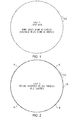
- the array of holes shown in Figure 1 comprises clearance holes 2 indicated by crosses, and dowel holes 4 indicated as circles.
- the holes 2, 4 are formed in a machining operation, performed on the casing, and the casing is subsequently inspected in a CMM process, to determine whether or not it falls within predetermined tolerances.
- the holes 2, 4 serve to locate the casing with respect to another component of the engine and to receive fasteners to secure the casing to the other component. Consequently, it is important that the holes are accurately positioned.
- the holes 2, 4 appear to lie on a true circle as seen in Figure 1 , the individual holes 2, 4 deviate slightly from the circle owing to the flexibility of the engine casing which causes it to deform when it is unsupported following the machining operation.
- the CMM process creates position data for the centrelines of the holes 2, 4 in the deformed condition of the casing.
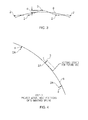
- This position data is supplied to a processor which, as shown in Figure 3 , generates a spline 6 which passes precisely through the centrelines of all of the holes 2,4.
- This spline is then smoothed in the processor to create a smoothed spline 8.
- the line of the spline is moved away from some or all of the hole centrelines. Consequently, the deviations d of the hole positions from the smoothed spline 8 can be regarded as "noise" in the overall hole pattern defined by the smoothed spline 8.
- the smoothed spline 8 may be derived by performing a smoothing process on the original spline 6, but alternatively the smoothed spline 8 may be derived from a spigot location diameter based on the positions of the dowel holes 4.
- the actual positions of the holes 2, 4 are projected onto the smoothed spline 8 to define projected hole positions 2A, and the individual deviations d of the actual positions of the centrelines of the holes 2,4 from the smoothed spline 8 are then recorded, as indicated in Figure 4 .
- a true circle is generated having a circumference which is identical to the peripheral length of the smoothed spline 8.
- the projected hole positions 2A on the smoothed spline 8 are mapped onto the circle 10 as projected hole positions 2B so that the distance along the circular arc of the circle 10 between adjacent projected positions is identical, for each respective pair of adjacent holes 2, 4, to the corresponding length along the smoothed spline 8.
- the projected hole positions 2B on the circle 10 are adjusted to establish constrained hole positions 2C.
- the deviation d between the actual hole position 2 and the hole position 2A projected on to the smoothed spline 8 is the same as the deviation between the hole position 2B projected on to the circle 10 and the constrained hole position 2C.
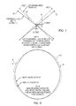
- the circle 10 is then transformed by both translation and rotation to achieve a best-fit between the constrained hole positions 2C, 4C and the nominal or theoretical hole positions 2, 4 derived from drawing data representing the intended form of the component.
- This transformation results in an offset X,Y as indicated in Figure 7 in the relative positions of the constrained hole positions 2C, 4C and the nominal positions 2, 4, and rotation of the circle 10, with the constrained hole positions 2C, 4C about the centre of the circuit 10 until the maximum positive angle ⁇ + between one respective pair of constrained and nominal hole positions 4C', 4' is equal to the maximum negative angle ⁇ - between another respective pair of constrained and nominal hole positions 4C", 4".
- the dowel holes 4 are used for this purpose, since it is desirable to base the correlation between the arrays of holes on the smoothed spline 8 and the best-fit circle 10 on locations which have a high accuracy requirement. Nevertheless, it is possible to use other groups of the holes 2, 4 to serve as the reference basis for this rotational adjustment.
- Figure 8 shows the best-fit circle 10, derived from the step referred to with regard to Figure 7 , superimposed on the smoothed spline 8. It will be appreciated that the process described with reference to Figures 1-7 yields the circle 10 which is the best fit of the measured holes 2, 4 of Figure 1 on a true circle. From Figure 8 , it is possible to establish the largest deflection a which the component needs to undergo in order to displace the actual positions of the holes 2, 4 as shown in Figure 1 on to the best-fit circle 10. Utilizing a 3D model of the component flange, the maximum load and stress are then calculated that would be produced by the required deformation of the flange to bring the smoothed spline 8 into coincidence with the best-fit circle 10. The calculated load and stress are then compared with predetermined values to establish whether or not the required flange deformation can be achieved without overstressing of the flange.
- the present invention provides a process by which position errors in features such as holes can be evaluated when measurement of the hole positions is performed while the component is in a deformed condition.
- Manipulation of the hole data creates a model of the hole array which conforms in shape to the nominal form (i.e. is circular in the embodiment described) while retaining any positioning errors. That model is then compared with a smoothed spline generated from the actual hole positions to determine whether or not the component can be adjusted to return the hole array to its nominal shape without overstressing or overloading the component, and errors in hole position can be determined.
- the process may be conducted on a coordinate measurement machine provided with a processor for carrying out the various calculating and transforming steps, without needing to physically support the component in its nominal shape, or its shape when assembled with neighbouring components.
Landscapes
- Physics & Mathematics (AREA)
- General Physics & Mathematics (AREA)
- Length Measuring Devices With Unspecified Measuring Means (AREA)
Abstract
Description
- This invention relates to a method of checking positional accuracy of features in a flexible component, and is particularly, although not exclusively, concerned with checking features such as holes in components such as gas turbine casings.
- Gas turbine casings are examples of components which are prone to distortion, for example under their own weight, when unsupported. This property can cause difficulties when inspecting such components, for example when checking the positional accuracy of an array of features, such as holes, which have been formed in the component in a machining process. Owing to distortion in the component, the holes move relative to their nominal positions with respect to a measurement datum. In order to avoid this problem, the conventional practice is to support the component during the inspection process in a build simulation fixture which holds the component in a nominal configuration, for example, a configuration which it assumes when fastened to another component. Such build simulation fixtures are, of necessity, large, and this causes handling and storage problems. Also, the fixtures need to be massive in order to prevent them from distorting, and they require regular calibration.
- According to the present invention there is provided a method of checking positional accuracy of features in a flexible component in which reference points of the features, in a nominal undeformed condition of the component, lie in nominal positions on a nominal line of predetermined form, the method comprising:
- (i) measuring the actual positions of the reference points of the features with the component in a deformed condition;
- (ii) generating a smoothed spline passing through or close to the actual positions of the reference points;
- (iii) mapping the measured positions of the features on to a best-fit line of the predetermined form;
- (iv) determining the maximum deflection of the component required to transform the smoothed spline into coincidence with the best-fit line; and
- (v) evaluating whether or not the maximum deflection lies within predetermined limits.
- The method may also comprise the step of comparing the actual position of the reference point of each feature with a respective nominal position of that reference point after transformation of the best-fit line into coincidence with the nominal line, and evaluating whether or not any deviation between the respective actual and nominal positions of each reference point falls within a respective predetermined positional tolerance.
- The predetermined form of the nominal line may be a circle, although other forms may be possible such as straight or curved lines, ellipses or other non-circular closed shapes. The features may be holes in the component, in which case the reference points may be the hole centrelines.
- The component may be an annular component, and the features, such as holes, may be provided in a flange of the component.
- The step of mapping the measured positions of the features on to a best-fit line may comprise:
- (a) generating a base spline passing through the reference point of each feature;
- (b) generating the smoothed spline from the base spline;
- (c) determining the deviation of the reference point of each feature from the smoothed spline;
- (d) constructing a base line of the predetermined form and having a length equal to the length of the smoothed spline, the reference points being spaced apart along the base line by the same distances as they are spaced apart along the smoothed spline; and
- (e) determining constrained positions of the reference points of the features which deviate from the base line by the same respective deviations of the reference points from the smoothed spline.
- The constrained positions may be manipulated by translation and/or rotation to achieve a best fit with the nominal hole positions.
- If the predetermined form of the nominal line is a circle, a manipulation of the constrained positions may be performed such that, within a group of the reference points of at least some of the features, the maximum positive angular deviation between the respective constrained and nominal positions occurring among those reference points is equal to the maximum negative angular deviation between the constrained and nominal positions occurring among those reference features.
- The component may be a casing of a gas turbine engine.
- The present invention also provides apparatus for performing a method as defined above, the apparatus comprising:
- i) a coordinate measuring machine for measuring the actual positions of the reference points of the features with the component in a deformed condition; and
- ii) processing equipment adapted to
- a) generate a smoothed spline passing through or close to the actual positions of the reference points;
- b) map the measured positions of the features on to a best-fit line of the predetermined form;
- c) determine the maximum deflection of the component required to transform the smoothed spline into coincidence with the best-fit line;
- d) evaluate whether or not the maximum deflection lies within predetermined limits.
- For a better understanding of the present invention, and to show more clearly how it may be carried into effect, reference will now be made, by way of example, to the accompanying drawings, in which:
-
Figure 1 represents measured positions of the centrelines of an array of holes in a flange of a gas turbine engine casing; -
Figure 2 shows a smoothed spline extending around the array of holes; -
Figure 3 is an enlarged view of a region of the smoothed splineFigure 2 ; -
Figure 4 indicates relationships between hole centreline positions and the smoothed spline; -
Figure 5 shows a circle onto which the hole centrelines are mapped; -
Figure 6 shows the relationship between constrained hole centreline positions and the circle ofFigure 5 ; -
Figure 7 represents a transformation to provide a best-fit between the hole centreline positions on the circle ofFigure 5 and nominal positions of the hole centrelines; and -
Figure 8 represents, in an exaggerated form, the relationship between the smoothed spline ofFigure 2 and the best-fit circle following the transformation ofFigure 7 . - The array of holes shown in
Figure 1 comprisesclearance holes 2 indicated by crosses, anddowel holes 4 indicated as circles. Theholes holes holes Figure 1 , theindividual holes - The CMM process creates position data for the centrelines of the
holes Figure 3 , generates aspline 6 which passes precisely through the centrelines of all of theholes spline 8. In the smoothing process, the line of the spline is moved away from some or all of the hole centrelines. Consequently, the deviations d of the hole positions from the smoothedspline 8 can be regarded as "noise" in the overall hole pattern defined by thesmoothed spline 8. - The smoothed
spline 8 may be derived by performing a smoothing process on theoriginal spline 6, but alternatively the smoothedspline 8 may be derived from a spigot location diameter based on the positions of thedowel holes 4. - The actual positions of the
holes spline 8 to define projectedhole positions 2A, and the individual deviations d of the actual positions of the centrelines of theholes spline 8 are then recorded, as indicated inFigure 4 . - In the next step, a true circle is generated having a circumference which is identical to the peripheral length of the smoothed
spline 8. The projectedhole positions 2A on the smoothedspline 8 are mapped onto thecircle 10 as projectedhole positions 2B so that the distance along the circular arc of thecircle 10 between adjacent projected positions is identical, for each respective pair ofadjacent holes smoothed spline 8. - Subsequently, using the deviations d recorded as described with reference
Figure 4 , the projectedhole positions 2B on thecircle 10 are adjusted to establish constrainedhole positions 2C. Thus, the deviation d between theactual hole position 2 and thehole position 2A projected on to the smoothedspline 8 is the same as the deviation between thehole position 2B projected on to thecircle 10 and theconstrained hole position 2C. - As shown in
Figure 7 , thecircle 10 is then transformed by both translation and rotation to achieve a best-fit between the constrainedhole positions theoretical hole positions Figure 7 in the relative positions of theconstrained hole positions nominal positions circle 10, with theconstrained hole positions circuit 10 until the maximum positive angle α+ between one respective pair of constrained andnominal hole positions 4C', 4' is equal to the maximum negative angle α- between another respective pair of constrained andnominal hole positions 4C", 4". It will be appreciated that, in the embodiment shown, thedowel holes 4 are used for this purpose, since it is desirable to base the correlation between the arrays of holes on the smoothedspline 8 and the best-fit circle 10 on locations which have a high accuracy requirement. Nevertheless, it is possible to use other groups of theholes -
Figure 8 shows the best-fit circle 10, derived from the step referred to with regard toFigure 7 , superimposed on the smoothedspline 8. It will be appreciated that the process described with reference toFigures 1-7 yields thecircle 10 which is the best fit of the measuredholes Figure 1 on a true circle. FromFigure 8 , it is possible to establish the largest deflection a which the component needs to undergo in order to displace the actual positions of theholes Figure 1 on to the best-fit circle 10. Utilising a 3D model of the component flange, the maximum load and stress are then calculated that would be produced by the required deformation of the flange to bring the smoothedspline 8 into coincidence with the best-fit circle 10. The calculated load and stress are then compared with predetermined values to establish whether or not the required flange deformation can be achieved without overstressing of the flange. - As a further step, actual position errors of the
holes fit circle 10 following the transformation described with reference toFigure 7 can be calculated on the basis of the maximum metal condition as prescribed by detail drawing requirements. This enables the creation of an output in the form of the following table:MAXIMUM DEFLECTION REQUIRED = 0.32m m LOAD REQUIRED = 30N MAX STRESS = 15Mpa ALL HOLES PASS POSITIONAL CHECK HOLE NUMBER ACTUAL ERROR MAX ERROR STATUS 1 0.028 0.512 PASSED ... ... ... ... ... ... ... ... ... ... ... ... 100 0.376 0.507 PASSED - It will be appreciated that the present invention provides a process by which position errors in features such as holes can be evaluated when measurement of the hole positions is performed while the component is in a deformed condition. Manipulation of the hole data creates a model of the hole array which conforms in shape to the nominal form (i.e. is circular in the embodiment described) while retaining any positioning errors. That model is then compared with a smoothed spline generated from the actual hole positions to determine whether or not the component can be adjusted to return the hole array to its nominal shape without overstressing or overloading the component, and errors in hole position can be determined.
- The process may be conducted on a coordinate measurement machine provided with a processor for carrying out the various calculating and transforming steps, without needing to physically support the component in its nominal shape, or its shape when assembled with neighbouring components.
Claims (13)
- A method of inspecting a flexible component, the component having features in which reference points of the features, in a nominal undeformed condition of the component, lie in nominal positions on a nominal line of predetermined form, the method comprising:(i) measuring the actual positions of the reference points of the features with the component in a deformed condition;(ii) generating a smoothed spline passing through or close to the actual positions of the reference points;(iii) mapping the measured positions of the features on to a best-fit line of the predetermined form;(iv) determining the maximum deflection of the component required to transform the smoothed spline into coincidence with the best-fit line; and(v) evaluating whether or not the maximum deflection lies within predetermined limits.
- A method as claimed in claim 1, further comprising the step of comparing the actual position of the reference point of each feature with a respective nominal position of that reference point after transformation of the smoothed spline into coincidence with the best-fit line, and evaluating whether or not any deviation between the respective actual and nominal positions of each reference point falls within a respective predetermined positional tolerance.
- A method as claimed in claim 1 or 2, in which the predetermined form of the nominal line is a circle.
- A method as claimed in any one of the preceding claims, in which the features are holes in the component.
- A method as claimed in claim 4, in which the reference points are the centrelines of the holes.
- A method as claimed in any one of the preceding claims, in which the component is an annular component, and the features are provided in a flange of the component.
- A method as claimed in any one of the preceding claims, in which the step of mapping the measured positions of the features on to a best-fit line comprises;(a) generating a base spline passing through the reference point of each feature;(b) generating the smoothed spline from the base spline;(c) determining the deviation of the reference point of each feature from the smoothed spline;(d) constructing a base line of the predetermined form and having a length equal to the length of the smoothed spline, the reference points being spaced apart along the base line by the same distances as they are spaced apart along the smoothed spline; and(e) determining constrained positions of the reference points of the features which deviate from the base line by the same respective deviations of the reference points from the smoothed spline.
- A method as claimed in claim 7, in which the constrained positions of the reference points are manipulated collectively to achieve the best-fit with the nominal positions of the reference points.
- A method as claimed in claim 8, in which the constrained positions are manipulated by translation and/or rotation.
- A method as claimed in any one of claims 7 to 9 when appendant to claim 3, in which manipulation of the constrained positions is performed such that, within a group of the reference points of at least some of the features, the maximum positive angular deviation between the respective constrained and nominal positions occurring among those reference points is equal to the maximum negative angular deviation between the constrained and nominal positions occurring among those reference features.
- A method of checking positional accuracy of features in a flexible component as claimed in claim 1 and substantially as described herein.
- A method as claimed in any one of the preceding claims, in which the component is a casing of a gas turbine engine.
- Apparatus for performing a method in accordance with any one of the preceding claims, the apparatus comprising:i) a coordinate measuring machine for measuring the actual positions of the reference points of the features with the component in a deformed condition; andii) processing equipment adapted toa) generate a smoothed spline passing through or close to the actual positions of the reference points;b) map the measured positions of the features on to a best-fit line of the predetermined form;c) determine the maximum deflection of the component required to transform the smoothed spline into coincidence with the best-fit line;d) evaluate whether or not the maximum deflection lies within predetermined limits.
Applications Claiming Priority (1)
| Application Number | Priority Date | Filing Date | Title |
|---|---|---|---|
| GB1105443.4A GB2489495B (en) | 2011-03-31 | 2011-03-31 | Checking positional accuracy of features |
Publications (2)
| Publication Number | Publication Date |
|---|---|
| EP2505960A1 true EP2505960A1 (en) | 2012-10-03 |
| EP2505960B1 EP2505960B1 (en) | 2017-03-01 |
Family
ID=44071721
Family Applications (1)
| Application Number | Title | Priority Date | Filing Date |
|---|---|---|---|
| EP12161423.4A Not-in-force EP2505960B1 (en) | 2011-03-31 | 2012-03-27 | Checking positional accuracy of features |
Country Status (3)
| Country | Link |
|---|---|
| US (1) | US20120253741A1 (en) |
| EP (1) | EP2505960B1 (en) |
| GB (1) | GB2489495B (en) |
Families Citing this family (1)
| Publication number | Priority date | Publication date | Assignee | Title |
|---|---|---|---|---|
| CN113449393B (en) * | 2021-06-25 | 2024-03-29 | 西安市群健航空精密制造有限公司 | Array hole processing method |
Citations (2)
| Publication number | Priority date | Publication date | Assignee | Title |
|---|---|---|---|---|
| US20100053191A1 (en) * | 2008-09-03 | 2010-03-04 | Hong Fu Jin Precision Industry (Shenzhen) Co., Ltd. | System and method for computing and displaying a roundness error of an object |
| US20100245843A1 (en) * | 2007-04-04 | 2010-09-30 | Zumbach Electronic Ag | Method for measuring the roundness of round profiles |
Family Cites Families (9)
| Publication number | Priority date | Publication date | Assignee | Title |
|---|---|---|---|---|
| US4344142A (en) * | 1974-05-23 | 1982-08-10 | Federal-Mogul Corporation | Direct digital control of rubber molding presses |
| EP0509809A3 (en) * | 1991-04-17 | 1993-06-09 | De Beers Industrial Diamond Division (Proprietary) Limited | Crusher roll wear monitoring apparatus and method |
| US5627761A (en) * | 1994-09-30 | 1997-05-06 | Carolina Power & Light Company | Internal alignment of rotating and stationary components within a steam or gas turbine |
| JPH095068A (en) * | 1995-06-19 | 1997-01-10 | Mitsui Petrochem Ind Ltd | Evaluation method of degree of deformation of articles |
| US6594555B2 (en) * | 2000-12-21 | 2003-07-15 | General Electric Company | Method for steam turbine halfshell alignment |
| JP4635392B2 (en) * | 2001-08-09 | 2011-02-23 | コニカミノルタホールディングス株式会社 | 3D object surface shape modeling apparatus and program |
| US7649614B2 (en) * | 2005-06-10 | 2010-01-19 | Asml Netherlands B.V. | Method of characterization, method of characterizing a process operation, and device manufacturing method |
| CN101248330B (en) * | 2005-06-28 | 2015-06-17 | 斯甘拉伊斯股份有限公司 | A system and method for measuring and mapping a surface relative to a reference |
| US7627428B2 (en) * | 2006-11-01 | 2009-12-01 | The University Of Akron | Method of evaluating surface deformation |
-
2011
- 2011-03-31 GB GB1105443.4A patent/GB2489495B/en not_active Expired - Fee Related
-
2012
- 2012-03-27 US US13/431,541 patent/US20120253741A1/en not_active Abandoned
- 2012-03-27 EP EP12161423.4A patent/EP2505960B1/en not_active Not-in-force
Patent Citations (2)
| Publication number | Priority date | Publication date | Assignee | Title |
|---|---|---|---|---|
| US20100245843A1 (en) * | 2007-04-04 | 2010-09-30 | Zumbach Electronic Ag | Method for measuring the roundness of round profiles |
| US20100053191A1 (en) * | 2008-09-03 | 2010-03-04 | Hong Fu Jin Precision Industry (Shenzhen) Co., Ltd. | System and method for computing and displaying a roundness error of an object |
Also Published As
| Publication number | Publication date |
|---|---|
| US20120253741A1 (en) | 2012-10-04 |
| GB201105443D0 (en) | 2011-05-18 |
| GB2489495A (en) | 2012-10-03 |
| GB2489495B (en) | 2013-03-06 |
| EP2505960B1 (en) | 2017-03-01 |
Similar Documents
| Publication | Publication Date | Title |
|---|---|---|
| CN111595279B (en) | Method for constructing actual coordinate system of large workpiece and application thereof | |
| JP4572403B2 (en) | Method and apparatus for aligning parts for inspection | |
| CN113601267B (en) | Method for establishing part machining coordinate system | |
| CN103991555A (en) | Automatic measuring method for digitalized airplane assembly | |
| CN108253906A (en) | A kind of axle housing circularity cylindricity detection device axis of workpiece location error compensation method | |
| CN105823417B (en) | A kind of method for turning station precision based on photogrammetric raising laser tracker | |
| CN109184819B (en) | A method of measuring the radial through-flow gap of a steam turbine by a laser tracking measurement system | |
| CN105783811B (en) | The detection method of pipe end center of circle three-dimensional coordinate | |
| US10132623B2 (en) | Method for measuring slant wall thickness dimension of hub | |
| RU2759013C1 (en) | Method for positioning elements of prefabricated structures in space | |
| CN110345867A (en) | A method of the space CMM Point Coordinates error is corrected based on inverse distance weighting | |
| CN110706292B (en) | Two-dimensional workbench error self-calibration method based on machine vision | |
| CN114089277A (en) | Three-dimensional sound source sound field reconstruction method and system | |
| CN107813293B (en) | Six-degree-of-freedom adjustable base device used in environment of flexibly processing double manipulators | |
| US20080229579A1 (en) | Reverse engineering method for disk and blade attachments | |
| EP2505960A1 (en) | Checking positional accuracy of features | |
| JP5610443B2 (en) | 3D dimension measurement method | |
| CN108110431A (en) | A kind of reflecting surface installation adjusting method of reflector antenna | |
| CN112815898B (en) | Method for converting ship three-dimensional data measurement into two-dimensional data measurement based on coordinate system | |
| CN118607111A (en) | A virtual pre-assembly method for steel structures based on parameter-driven joint mapping | |
| US10944491B2 (en) | Method and system for positioning a device under test within a test area | |
| CN116363080A (en) | 3D gluing anomaly detection method and device based on contour synchronous time series | |
| US20170205258A1 (en) | Test fixture, system and method for concentricity measurement tool calibration | |
| CN110065072B (en) | Verification Method of Robot Repeated Positioning Accuracy | |
| CN110233355B (en) | Installation and adjustment method of large antenna beam waveguide reflection surface |
Legal Events
| Date | Code | Title | Description |
|---|---|---|---|
| PUAI | Public reference made under article 153(3) epc to a published international application that has entered the european phase |
Free format text: ORIGINAL CODE: 0009012 |
|
| AK | Designated contracting states |
Kind code of ref document: A1 Designated state(s): AL AT BE BG CH CY CZ DE DK EE ES FI FR GB GR HR HU IE IS IT LI LT LU LV MC MK MT NL NO PL PT RO RS SE SI SK SM TR |
|
| AX | Request for extension of the european patent |
Extension state: BA ME |
|
| 17P | Request for examination filed |
Effective date: 20130403 |
|
| 17Q | First examination report despatched |
Effective date: 20150619 |
|
| RAP1 | Party data changed (applicant data changed or rights of an application transferred) |
Owner name: ROLLS-ROYCE PLC |
|
| GRAP | Despatch of communication of intention to grant a patent |
Free format text: ORIGINAL CODE: EPIDOSNIGR1 |
|
| STAA | Information on the status of an ep patent application or granted ep patent |
Free format text: STATUS: GRANT OF PATENT IS INTENDED |
|
| INTG | Intention to grant announced |
Effective date: 20161110 |
|
| GRAS | Grant fee paid |
Free format text: ORIGINAL CODE: EPIDOSNIGR3 |
|
| GRAA | (expected) grant |
Free format text: ORIGINAL CODE: 0009210 |
|
| STAA | Information on the status of an ep patent application or granted ep patent |
Free format text: STATUS: THE PATENT HAS BEEN GRANTED |
|
| AK | Designated contracting states |
Kind code of ref document: B1 Designated state(s): AL AT BE BG CH CY CZ DE DK EE ES FI FR GB GR HR HU IE IS IT LI LT LU LV MC MK MT NL NO PL PT RO RS SE SI SK SM TR |
|
| REG | Reference to a national code |
Ref country code: GB Ref legal event code: FG4D |
|
| REG | Reference to a national code |
Ref country code: CH Ref legal event code: EP Ref country code: AT Ref legal event code: REF Ref document number: 871893 Country of ref document: AT Kind code of ref document: T Effective date: 20170315 |
|
| REG | Reference to a national code |
Ref country code: IE Ref legal event code: FG4D |
|
| REG | Reference to a national code |
Ref country code: FR Ref legal event code: PLFP Year of fee payment: 6 |
|
| REG | Reference to a national code |
Ref country code: DE Ref legal event code: R096 Ref document number: 602012029114 Country of ref document: DE |
|
| REG | Reference to a national code |
Ref country code: NL Ref legal event code: MP Effective date: 20170301 |
|
| REG | Reference to a national code |
Ref country code: LT Ref legal event code: MG4D |
|
| REG | Reference to a national code |
Ref country code: AT Ref legal event code: MK05 Ref document number: 871893 Country of ref document: AT Kind code of ref document: T Effective date: 20170301 |
|
| PG25 | Lapsed in a contracting state [announced via postgrant information from national office to epo] |
Ref country code: FI Free format text: LAPSE BECAUSE OF FAILURE TO SUBMIT A TRANSLATION OF THE DESCRIPTION OR TO PAY THE FEE WITHIN THE PRESCRIBED TIME-LIMIT Effective date: 20170301 Ref country code: NO Free format text: LAPSE BECAUSE OF FAILURE TO SUBMIT A TRANSLATION OF THE DESCRIPTION OR TO PAY THE FEE WITHIN THE PRESCRIBED TIME-LIMIT Effective date: 20170601 Ref country code: GR Free format text: LAPSE BECAUSE OF FAILURE TO SUBMIT A TRANSLATION OF THE DESCRIPTION OR TO PAY THE FEE WITHIN THE PRESCRIBED TIME-LIMIT Effective date: 20170602 Ref country code: LT Free format text: LAPSE BECAUSE OF FAILURE TO SUBMIT A TRANSLATION OF THE DESCRIPTION OR TO PAY THE FEE WITHIN THE PRESCRIBED TIME-LIMIT Effective date: 20170301 Ref country code: HR Free format text: LAPSE BECAUSE OF FAILURE TO SUBMIT A TRANSLATION OF THE DESCRIPTION OR TO PAY THE FEE WITHIN THE PRESCRIBED TIME-LIMIT Effective date: 20170301 |
|
| PG25 | Lapsed in a contracting state [announced via postgrant information from national office to epo] |
Ref country code: BG Free format text: LAPSE BECAUSE OF FAILURE TO SUBMIT A TRANSLATION OF THE DESCRIPTION OR TO PAY THE FEE WITHIN THE PRESCRIBED TIME-LIMIT Effective date: 20170601 Ref country code: ES Free format text: LAPSE BECAUSE OF FAILURE TO SUBMIT A TRANSLATION OF THE DESCRIPTION OR TO PAY THE FEE WITHIN THE PRESCRIBED TIME-LIMIT Effective date: 20170301 Ref country code: SE Free format text: LAPSE BECAUSE OF FAILURE TO SUBMIT A TRANSLATION OF THE DESCRIPTION OR TO PAY THE FEE WITHIN THE PRESCRIBED TIME-LIMIT Effective date: 20170301 Ref country code: RS Free format text: LAPSE BECAUSE OF FAILURE TO SUBMIT A TRANSLATION OF THE DESCRIPTION OR TO PAY THE FEE WITHIN THE PRESCRIBED TIME-LIMIT Effective date: 20170301 Ref country code: LV Free format text: LAPSE BECAUSE OF FAILURE TO SUBMIT A TRANSLATION OF THE DESCRIPTION OR TO PAY THE FEE WITHIN THE PRESCRIBED TIME-LIMIT Effective date: 20170301 Ref country code: AT Free format text: LAPSE BECAUSE OF FAILURE TO SUBMIT A TRANSLATION OF THE DESCRIPTION OR TO PAY THE FEE WITHIN THE PRESCRIBED TIME-LIMIT Effective date: 20170301 |
|
| PG25 | Lapsed in a contracting state [announced via postgrant information from national office to epo] |
Ref country code: NL Free format text: LAPSE BECAUSE OF FAILURE TO SUBMIT A TRANSLATION OF THE DESCRIPTION OR TO PAY THE FEE WITHIN THE PRESCRIBED TIME-LIMIT Effective date: 20170301 |
|
| PG25 | Lapsed in a contracting state [announced via postgrant information from national office to epo] |
Ref country code: IT Free format text: LAPSE BECAUSE OF FAILURE TO SUBMIT A TRANSLATION OF THE DESCRIPTION OR TO PAY THE FEE WITHIN THE PRESCRIBED TIME-LIMIT Effective date: 20170301 Ref country code: SK Free format text: LAPSE BECAUSE OF FAILURE TO SUBMIT A TRANSLATION OF THE DESCRIPTION OR TO PAY THE FEE WITHIN THE PRESCRIBED TIME-LIMIT Effective date: 20170301 Ref country code: CZ Free format text: LAPSE BECAUSE OF FAILURE TO SUBMIT A TRANSLATION OF THE DESCRIPTION OR TO PAY THE FEE WITHIN THE PRESCRIBED TIME-LIMIT Effective date: 20170301 Ref country code: RO Free format text: LAPSE BECAUSE OF FAILURE TO SUBMIT A TRANSLATION OF THE DESCRIPTION OR TO PAY THE FEE WITHIN THE PRESCRIBED TIME-LIMIT Effective date: 20170301 Ref country code: EE Free format text: LAPSE BECAUSE OF FAILURE TO SUBMIT A TRANSLATION OF THE DESCRIPTION OR TO PAY THE FEE WITHIN THE PRESCRIBED TIME-LIMIT Effective date: 20170301 |
|
| REG | Reference to a national code |
Ref country code: CH Ref legal event code: PL |
|
| PG25 | Lapsed in a contracting state [announced via postgrant information from national office to epo] |
Ref country code: PL Free format text: LAPSE BECAUSE OF FAILURE TO SUBMIT A TRANSLATION OF THE DESCRIPTION OR TO PAY THE FEE WITHIN THE PRESCRIBED TIME-LIMIT Effective date: 20170301 Ref country code: SM Free format text: LAPSE BECAUSE OF FAILURE TO SUBMIT A TRANSLATION OF THE DESCRIPTION OR TO PAY THE FEE WITHIN THE PRESCRIBED TIME-LIMIT Effective date: 20170301 Ref country code: PT Free format text: LAPSE BECAUSE OF FAILURE TO SUBMIT A TRANSLATION OF THE DESCRIPTION OR TO PAY THE FEE WITHIN THE PRESCRIBED TIME-LIMIT Effective date: 20170703 Ref country code: IS Free format text: LAPSE BECAUSE OF FAILURE TO SUBMIT A TRANSLATION OF THE DESCRIPTION OR TO PAY THE FEE WITHIN THE PRESCRIBED TIME-LIMIT Effective date: 20170701 |
|
| REG | Reference to a national code |
Ref country code: DE Ref legal event code: R097 Ref document number: 602012029114 Country of ref document: DE |
|
| REG | Reference to a national code |
Ref country code: IE Ref legal event code: MM4A |
|
| PLBE | No opposition filed within time limit |
Free format text: ORIGINAL CODE: 0009261 |
|
| STAA | Information on the status of an ep patent application or granted ep patent |
Free format text: STATUS: NO OPPOSITION FILED WITHIN TIME LIMIT |
|
| PG25 | Lapsed in a contracting state [announced via postgrant information from national office to epo] |
Ref country code: LU Free format text: LAPSE BECAUSE OF NON-PAYMENT OF DUE FEES Effective date: 20170327 Ref country code: MC Free format text: LAPSE BECAUSE OF FAILURE TO SUBMIT A TRANSLATION OF THE DESCRIPTION OR TO PAY THE FEE WITHIN THE PRESCRIBED TIME-LIMIT Effective date: 20170301 Ref country code: DK Free format text: LAPSE BECAUSE OF FAILURE TO SUBMIT A TRANSLATION OF THE DESCRIPTION OR TO PAY THE FEE WITHIN THE PRESCRIBED TIME-LIMIT Effective date: 20170301 |
|
| 26N | No opposition filed |
Effective date: 20171204 |
|
| PG25 | Lapsed in a contracting state [announced via postgrant information from national office to epo] |
Ref country code: CH Free format text: LAPSE BECAUSE OF NON-PAYMENT OF DUE FEES Effective date: 20170331 Ref country code: LI Free format text: LAPSE BECAUSE OF NON-PAYMENT OF DUE FEES Effective date: 20170331 Ref country code: SI Free format text: LAPSE BECAUSE OF FAILURE TO SUBMIT A TRANSLATION OF THE DESCRIPTION OR TO PAY THE FEE WITHIN THE PRESCRIBED TIME-LIMIT Effective date: 20170301 Ref country code: IE Free format text: LAPSE BECAUSE OF NON-PAYMENT OF DUE FEES Effective date: 20170327 |
|
| REG | Reference to a national code |
Ref country code: BE Ref legal event code: MM Effective date: 20170331 |
|
| REG | Reference to a national code |
Ref country code: FR Ref legal event code: PLFP Year of fee payment: 7 |
|
| PG25 | Lapsed in a contracting state [announced via postgrant information from national office to epo] |
Ref country code: BE Free format text: LAPSE BECAUSE OF NON-PAYMENT OF DUE FEES Effective date: 20170331 |
|
| PG25 | Lapsed in a contracting state [announced via postgrant information from national office to epo] |
Ref country code: MT Free format text: LAPSE BECAUSE OF NON-PAYMENT OF DUE FEES Effective date: 20170327 |
|
| PG25 | Lapsed in a contracting state [announced via postgrant information from national office to epo] |
Ref country code: HU Free format text: LAPSE BECAUSE OF FAILURE TO SUBMIT A TRANSLATION OF THE DESCRIPTION OR TO PAY THE FEE WITHIN THE PRESCRIBED TIME-LIMIT; INVALID AB INITIO Effective date: 20120327 |
|
| PG25 | Lapsed in a contracting state [announced via postgrant information from national office to epo] |
Ref country code: CY Free format text: LAPSE BECAUSE OF NON-PAYMENT OF DUE FEES Effective date: 20170301 |
|
| PG25 | Lapsed in a contracting state [announced via postgrant information from national office to epo] |
Ref country code: MK Free format text: LAPSE BECAUSE OF FAILURE TO SUBMIT A TRANSLATION OF THE DESCRIPTION OR TO PAY THE FEE WITHIN THE PRESCRIBED TIME-LIMIT Effective date: 20170301 |
|
| PG25 | Lapsed in a contracting state [announced via postgrant information from national office to epo] |
Ref country code: TR Free format text: LAPSE BECAUSE OF FAILURE TO SUBMIT A TRANSLATION OF THE DESCRIPTION OR TO PAY THE FEE WITHIN THE PRESCRIBED TIME-LIMIT Effective date: 20170301 |
|
| PGFP | Annual fee paid to national office [announced via postgrant information from national office to epo] |
Ref country code: GB Payment date: 20200327 Year of fee payment: 9 Ref country code: DE Payment date: 20200327 Year of fee payment: 9 |
|
| PGFP | Annual fee paid to national office [announced via postgrant information from national office to epo] |
Ref country code: FR Payment date: 20200325 Year of fee payment: 9 |
|
| PG25 | Lapsed in a contracting state [announced via postgrant information from national office to epo] |
Ref country code: AL Free format text: LAPSE BECAUSE OF FAILURE TO SUBMIT A TRANSLATION OF THE DESCRIPTION OR TO PAY THE FEE WITHIN THE PRESCRIBED TIME-LIMIT Effective date: 20170301 |
|
| REG | Reference to a national code |
Ref country code: DE Ref legal event code: R119 Ref document number: 602012029114 Country of ref document: DE |
|
| GBPC | Gb: european patent ceased through non-payment of renewal fee |
Effective date: 20210327 |
|
| PG25 | Lapsed in a contracting state [announced via postgrant information from national office to epo] |
Ref country code: DE Free format text: LAPSE BECAUSE OF NON-PAYMENT OF DUE FEES Effective date: 20211001 Ref country code: FR Free format text: LAPSE BECAUSE OF NON-PAYMENT OF DUE FEES Effective date: 20210331 Ref country code: GB Free format text: LAPSE BECAUSE OF NON-PAYMENT OF DUE FEES Effective date: 20210327 |