EP2505907A1 - Portable electric lamp including a power supply and communication connector - Google Patents
Portable electric lamp including a power supply and communication connector Download PDFInfo
- Publication number
- EP2505907A1 EP2505907A1 EP12354022A EP12354022A EP2505907A1 EP 2505907 A1 EP2505907 A1 EP 2505907A1 EP 12354022 A EP12354022 A EP 12354022A EP 12354022 A EP12354022 A EP 12354022A EP 2505907 A1 EP2505907 A1 EP 2505907A1
- Authority
- EP
- European Patent Office
- Prior art keywords
- connector
- module
- power supply
- support member
- rear support
- Prior art date
- Legal status (The legal status is an assumption and is not a legal conclusion. Google has not performed a legal analysis and makes no representation as to the accuracy of the status listed.)
- Granted
Links
- 238000007789 sealing Methods 0.000 claims description 3
- 238000000926 separation method Methods 0.000 abstract 1
- 230000015572 biosynthetic process Effects 0.000 description 2
- 239000004020 conductor Substances 0.000 description 2
- 238000010586 diagram Methods 0.000 description 2
- 235000019504 cigarettes Nutrition 0.000 description 1
- 230000007423 decrease Effects 0.000 description 1
- 238000003780 insertion Methods 0.000 description 1
- 230000037431 insertion Effects 0.000 description 1
- 238000002955 isolation Methods 0.000 description 1
Images


Classifications
-
- F—MECHANICAL ENGINEERING; LIGHTING; HEATING; WEAPONS; BLASTING
- F21—LIGHTING
- F21L—LIGHTING DEVICES OR SYSTEMS THEREOF, BEING PORTABLE OR SPECIALLY ADAPTED FOR TRANSPORTATION
- F21L4/00—Electric lighting devices with self-contained electric batteries or cells
- F21L4/08—Electric lighting devices with self-contained electric batteries or cells characterised by means for in situ recharging of the batteries or cells
-
- F—MECHANICAL ENGINEERING; LIGHTING; HEATING; WEAPONS; BLASTING
- F21—LIGHTING
- F21V—FUNCTIONAL FEATURES OR DETAILS OF LIGHTING DEVICES OR SYSTEMS THEREOF; STRUCTURAL COMBINATIONS OF LIGHTING DEVICES WITH OTHER ARTICLES, NOT OTHERWISE PROVIDED FOR
- F21V23/00—Arrangement of electric circuit elements in or on lighting devices
- F21V23/06—Arrangement of electric circuit elements in or on lighting devices the elements being coupling devices, e.g. connectors
-
- F—MECHANICAL ENGINEERING; LIGHTING; HEATING; WEAPONS; BLASTING
- F21—LIGHTING
- F21V—FUNCTIONAL FEATURES OR DETAILS OF LIGHTING DEVICES OR SYSTEMS THEREOF; STRUCTURAL COMBINATIONS OF LIGHTING DEVICES WITH OTHER ARTICLES, NOT OTHERWISE PROVIDED FOR
- F21V17/00—Fastening of component parts of lighting devices, e.g. shades, globes, refractors, reflectors, filters, screens, grids or protective cages
- F21V17/10—Fastening of component parts of lighting devices, e.g. shades, globes, refractors, reflectors, filters, screens, grids or protective cages characterised by specific fastening means or way of fastening
- F21V17/16—Fastening of component parts of lighting devices, e.g. shades, globes, refractors, reflectors, filters, screens, grids or protective cages characterised by specific fastening means or way of fastening by deformation of parts; Snap action mounting
- F21V17/164—Fastening of component parts of lighting devices, e.g. shades, globes, refractors, reflectors, filters, screens, grids or protective cages characterised by specific fastening means or way of fastening by deformation of parts; Snap action mounting the parts being subjected to bending, e.g. snap joints
Definitions
- Portable electric lighting lamps are known, the accumulator of which is associated with a power supply and communication connector, of the Universal Serial Bus (USB) type, which can be connected to an external source.
- USB Universal Serial Bus
- the lamp can first be recharged, among others from a power outlet, a cigarette lighter, or a solar panel. It can also connect this connector to a computer, so as to adjust different parameters of the lamp, such as its autonomy or its lighting power.
- the USB connector is usually formed by a socket, which must be connected to the above-mentioned source via an independent connecting cable, to recharge the battery, and set the lighting level. It is therefore it is necessary to always carry the connecting cable with the lamp.
- the object of the invention is to provide a portable electric lighting lamp, the USB connector can be reliably connected to an external source, regardless of the conditions of use.
- the invention also aims at providing such a lamp, the connection between the connector and the external source can be implemented conveniently, and without connecting cable.
- the USB connector is inserted into a housing, which ensures its integrity, whatever the external conditions.
- the housing is waterproof making the connector insensitive to moisture. It can thus ensure its electrical function, once removed from the housing.
- the connector is of the male type, and can be plugged directly into a socket of the external source, such as a computer port. This eliminates the use of an external connecting cable, as used in the state of the art.
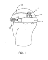
- the lamp 1 firstly comprises a front lighting device (not shown), LED type or other appropriate type. With reference in particular to the figure 1 this lamp further comprises a rear support member 10, secured to the front device by laces 100 or fastening straps. As a variant, provision may be made for this front device and this rear support member to be held on the user's head by any other appropriate means, in particular an elastic band of conventional type.
- the rear support member 10 which can cooperate with a power module 50 as will be seen in what follows, is triangular in shape, with the horizontal base. It is provided with two contact pads 12, intended to improve the comfort of the user.
- This rear support member 10 is hollowed with a notch 14 for receiving the module 50, which is bordered by a beach 16. The latter is provided, in its middle part, with an elastic tongue 18, adapted to ensure the snap of the module 50, as will be seen below.
- the upper part of the support member 10 comprises two lateral cheeks 20, on which is mounted a cap 22, which can pivot about a transverse axis A.
- This cap 22 comprises a closed bottom 24, two side walls 26 also closed, and an outlet 28 arranged opposite the closed bottom 24.
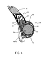
- the supply module 50 comprises a housing 52, made in two parts, namely a body 54 which is secured to a shell 56, by any appropriate means.
- This housing 52 defines an interior volume V, in which is housed a rechargeable battery 58, of any type known per se. The latter is connected, in a conventional manner, to the lighting module by a cable 60, partially illustrated on the figure 1 .
- the accumulator 58 is further associated with a power supply and communication connector 62, of conventional type.
- a power supply and communication connector 62 of conventional type.
- the connector 62 protrudes out of the internal volume V via an orifice 64 which is closed off by a seal 66.
- the latter has a flange 68, which rests against a seat 70 of the housing 52.
- the body 54 comprises a boss 72, adapted to cooperate by snapping with the tongue 18 of the support member 10.
- the feed module 50 is disengaged from the support member 10, which corresponds to the arrangement of the figures 2 and 5 .
- the connector 62 is freely accessible, so that it can be connected to an external source, either for charging, or for programming its parameters, or both simultaneously.
- the presence of a male USB connector allows to connect directly to a female USB socket of a computer, or an external source without using an additional cable.
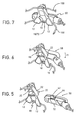
- the module 50 it is first of all to thread the free end of the connector 62 inside the cap 22.
- This operation is facilitated by the possibility of pivoting the cap, which allows a simplified positioning.
- the seal 66 comes into contact with the side walls 26 of the latter.
- the walls 26 are slightly flared, so that their section gradually decreases opposite the outlet 28 of the cap. At the end of the race, as illustrated in figures 3 and 6 the seal is thus compressed against the walls of the cap.
- the assembly formed by the cap 22 and the feed module 50, is then rotated about the axis A, according to the arrow f1 of the figures 3 and 6 .
- the boss 72 of the module 50 compresses the tongue 18 of the support member 10, which makes it possible to immobilize the latter with respect to the module 50, by elastic latching.
- the connector is received in a sealed housing 80, delimited by the bottom 24 and the walls 26 of the cap 22, as well as by the internal volume of the housing 52.
- the tongue 18 exerts a force f2, which tends pushing the feed module 50 upwards and compressing the seal 66, which further improves the seal.
- the power supply module 50 When the power supply module 50 is fixed on the support member 10, the user can use the lamp in the usual way. Then, if he wants to either recharge the lamp or change the programming, it switches the module to the opposite of the arrow f2 above, so as to disengage the module 50 relative to the support member 10. Under these conditions, the lamp is again in its configuration of figures 2 and 5 , so that the user can directly access the USB connector 62.
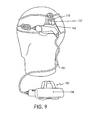
- FIGS 8 and 9 illustrate an alternative embodiment of the invention, in which the power supply module 150 is remote.
- the mechanical members similar to those of Figures 1 to 7 are assigned the same reference numbers, increased by 100.
- the embodiment of the figures 8 and 9 provides a feed assembly formed of two modules, and not a single module 50 as in the embodiment of Figures 1 to 7 . More specifically, this assembly firstly comprises a first module 150, in the interior volume of which is received the accumulator 158. This first module 150 is connected to a second module 150 ', via a cable connection 151, or any equivalent member. Furthermore, this second module 150 'is equipped with the USB connector 162, which protrudes via an orifice, closed off by the seal 166. Finally, the support member 110 is structurally identical to that described above. above.
- the implementation of the lamp of the figures 8 and 9 involves, as in the first mode, the insertion of the USB connector 162 in the cap 122, then the snap fastening of the module 150 'on the support member 110.
- the cooperation of this module 150 'with the support member 110 is similar to that intervening between the single module 50 and the support member 10.
- the module 150 is offset from that 150', in particular to preserve the accumulator to the severe weather conditions.
- the invention is not limited to the examples described and shown. Thus one can first of all provide that the battery supply assembly is not mounted on the rear support member, but on the contrary on the front lighting device.
- the front device is for example provided with latching means, similar or equivalent to those described above, which equip the rear support member.
- the power and communication connector is not of the male type, but of the female type. In both cases, the USB connector is protected in a closed compartment when in the locked position.
- USB power and communication connector is not USB type, but any other equivalent type appropriate.
- the figure 10 represents the wiring diagram of the USB connector 62 in the power supply module 50.
- the USB connector is connected to an electronic card CE located in the module, and comprising a regulator circuit 200 for charging the battery 58, and a processor 201 for adjusting the lamp parameters.
- the output of the accumulator 58 is connected by power conductors 202 to the lighting module for supplying the lamp.
- the output of the processor 201 is connected by a data bus 203 to the same lighting module for the operating parameterization of the lamp.
- the four conductors 202 and 203 are arranged in the same sheath constituting the cable 60 of the figure 1 .
Landscapes
- Engineering & Computer Science (AREA)
- General Engineering & Computer Science (AREA)
- Arrangement Of Elements, Cooling, Sealing, Or The Like Of Lighting Devices (AREA)
Abstract
Description
L'invention est relative à une lampe d'éclairage électrique portative, notamment une lampe frontale, comprenant
- un dispositif d'éclairage avant
- un ensemble d'alimentation électrique du module d'éclairage, cet ensemble comprenant un accumulateur et un connecteur d'alimentation et de communication, de type Bus Série Universel,
- un organe d'appui arrière, et
- des moyens de maintien de la lampe sur la tête d'un utilisateur, reliant le dispositif d'éclairage avant et l'organe d'appui arrière.
- front lighting
- a power supply unit of the lighting module, this assembly comprising an accumulator and a power supply and communication connector, of the Universal Serial Bus type,
- a rear support member, and
- means for holding the lamp on the head of a user, connecting the front lighting device and the rear support member.
On connaît des lampes d'éclairage électrique portatives, dont l'accumulateur est associé à un connecteur d'alimentation et de communication, de type USB (Universal Serial Bus), susceptible d'être reliée à une source extérieure. De la sorte, la lampe peut tout d'abord être rechargée, entre autres depuis une prise secteur, un allume-cigare, ou encore un panneau solaire. On peut également relier ce connecteur à un ordinateur, de façon à ajuster différents paramètres de la lampe, tels que notamment son autonomie ou sa puissance d'éclairage.Portable electric lighting lamps are known, the accumulator of which is associated with a power supply and communication connector, of the Universal Serial Bus (USB) type, which can be connected to an external source. In this way, the lamp can first be recharged, among others from a power outlet, a cigarette lighter, or a solar panel. It can also connect this connector to a computer, so as to adjust different parameters of the lamp, such as its autonomy or its lighting power.
Le connecteur USB est formé généralement à une prise femelle, qui doit être reliée à la source précitée via un câble de liaison indépendant, pour assurer la recharge de l'accumulateur, et le paramétrage du niveau d'éclairage. Il est donc nécessaire d'emporter en permanence le câble de liaison avec la lampe.The USB connector is usually formed by a socket, which must be connected to the above-mentioned source via an independent connecting cable, to recharge the battery, and set the lighting level. It is therefore it is necessary to always carry the connecting cable with the lamp.
L'objet de l'invention consiste à réaliser une lampe d'éclairage électrique portative, dont le connecteur USB peut être relié de façon fiable à une source extérieure, indépendamment des conditions d'utilisation. L'invention vise également à proposer une telle lampe, dont la liaison entre le connecteur et la source extérieure peut être mise en oeuvre de manière commode, et sans câble de liaison.The object of the invention is to provide a portable electric lighting lamp, the USB connector can be reliably connected to an external source, regardless of the conditions of use. The invention also aims at providing such a lamp, the connection between the connector and the external source can be implemented conveniently, and without connecting cable.
La lampe selon l'invention est caractérisée en ce que :
- l'ensemble d'alimentation électrique comprend au moins un premier module qui est pourvu du connecteur USB, ledit premier module possédant des moyens de fixation amovible sur l'organe d'appui arrière pour définir des positions respectives de fixation et de désolidarisation, avec formation dans la position de fixation, d'un logement de réception et de protection du connecteur USB,
l'organe d'appui arrière comporte un élément creux pivotant de réception dudit connecteur.
- the power supply assembly comprises at least a first module which is provided with the USB connector, said first module having removable attachment means on the rear support member to define respective positions of fixing and uncoupling, with formation in the position of attachment, a housing for receiving and protecting the USB connector,
the rear support member comprises a pivotable hollow element for receiving said connector.
Conformément à l'invention, le connecteur USB est introduit dans un logement, ce qui permet de garantir son intégrité, quelles que soient les conditions extérieures. De préférence, le logement est étanche rendant le connecteur insensible à l'humidité. Il peut ainsi assurer sa fonction électrique, une fois extrait hors du logement.According to the invention, the USB connector is inserted into a housing, which ensures its integrity, whatever the external conditions. Preferably, the housing is waterproof making the connector insensitive to moisture. It can thus ensure its electrical function, once removed from the housing.
Le connecteur est de type mâle, et peut être branché directement sur une prise femelle de la source extérieure, telle qu'un port d'ordinateur. Ceci permet de s'affranchir de l'emploi d'un câble extérieur de liaison, tel qu'utilisé dans l'état de la technique.The connector is of the male type, and can be plugged directly into a socket of the external source, such as a computer port. This eliminates the use of an external connecting cable, as used in the state of the art.
La lampe conforme à l'invention peut comporter tout ou partie des caractéristiques suivantes, prises isolément ou selon toute combinaison techniquement compatible :
- l'organe d'appui arrière comporte un élément creux possédant un fond et des parois latérales fermées, et le connecteur est bordé par un joint d'étanchéité, le joint étant comprimé contre les parois de l'élément creux, dans la position de fixation.
- les moyens de fixation amovible sont des moyens de fixation par encliquetage élastique.
- l'organe d'appui arrière ou le dispositif d'éclairage avant comprend un élément d'encliquetage élastique, apte à repousser le joint d'étanchéité vers l'intérieur de l'élément creux, dans la position de fixation.
- le connecteur est un connecteur mâle.
- le premier module est introduit dans une échancrure, ménagée dans l'organe d'appui arrière.
- l'ensemble d'alimentation électrique est formé par le premier module, qui est pourvu à la fois de l'accumulateur et du connecteur.
- l'ensemble d'alimentation électrique comprend le premier module, qui est pourvu du connecteur, ainsi qu'un second module, pourvu de l'accumulateur, ces deux modules étant reliés par des moyens de connexion électrique.
- the rear support member comprises a hollow member having a bottom and closed side walls, and the connector is bordered by a seal, the seal being compressed against the walls of the hollow member, in the fixing position .
- the removable fastening means are elastic snap fastening means.
- the rear support member or the front lighting device comprises an elastic detent element, able to push the seal towards the inside of the hollow element, in the fixing position.
- the connector is a male connector.
- the first module is introduced into a notch, formed in the rear support member.
- the power supply assembly is formed by the first module, which is provided with both the accumulator and the connector.
- the power supply assembly comprises the first module, which is provided with the connector, and a second module, provided with the accumulator, these two modules being connected by electrical connection means.
L'invention concerne aussi un ensemble d'alimentation électrique appartenant à une lampe d'éclairage électrique portative, cet ensemble comprenant
- des moyens de fixation amovible sur l'organe d'appui arrière,
- un accumulateur et un connecteur d'alimentation et de communication, de type Bus Série Universel (USB),
- un joint d'étanchéité entourant le connecteur de façon à définir, avec l'organe d'appui arrière, un logement étanche de réception du connecteur, dans la position de fixation.
- detachable fastening means on the rear support member,
- an accumulator and a power and communication connector, of the Universal Serial Bus (USB) type,
- a seal surrounding the connector so as to define, with the rear support member, a sealing housing for receiving the connector, in the fixing position.
D'autres avantages et caractéristiques ressortiront plus clairement de la description qui va suivre d'un mode particulier de réalisation de l'invention donné à titre d'exemple non limitatif et représenté aux dessins annexés, dans lesquels :
- la
figure 1 est une vue en perspective d'une lampe portative selon l'invention, - les
figures 2 à 4 sont des vues en en coupe longitudinale, illustrant à plus grande échelle un organe d'appui arrière et un module d'alimentation électrique appartenant à cette lampe, dans des positions respectivement extraite, déverrouillée et verrouillée, - les
figures 5 à 7 sont des vues en perspective de l'organe d'appui arrière et du module d'alimentation électrique, dans les positions respectivement extraite, déverrouillée et verrouillée, - les
figures 8 et9 sont des vues en perspective d'une variante de l'invention à module d'alimentation déportée, illustrée dans des positions respectivement extraite et verrouillée, - la
figure 10 montre le schéma de la carte électronique de commande pour la recharge de l'accumulateur et le paramétrage de la lampe.
- the
figure 1 is a perspective view of a portable lamp according to the invention, - the
Figures 2 to 4 are views in longitudinal section, illustrating on a larger scale a rear support member and a power supply module belonging to this lamp, in positions respectively extracted, unlocked and locked, - the
Figures 5 to 7 are perspective views of the rear support member and the power supply module, respectively in the extracted, unlocked and locked positions, - the
figures 8 and9 are perspective views of a variant of the invention with a remote power supply module, illustrated in respectively extracted and locked positions, - the
figure 10 shows the circuit diagram of the control board for charging the battery and setting the lamp.
Dans ce qui suit, les termes « avant », « arrière », « supérieur », « inférieur », « horizontal » et « vertical » sont relatifs à une lampe portée par un utilisateur en position debout, tête droite. La lampe 1 conforme à l'invention comprend tout d'abord un dispositif d'éclairage avant (non représenté), de type LED ou autre type approprié. En référence notamment à la
Sur les
La partie supérieure de l'organe d'appui 10 comporte deux joues latérales 20, sur lesquelles est montée une coiffe 22, laquelle peut pivoter autour d'un axe transversal A. Cette coiffe 22 comprend un fond fermé 24, deux parois latérales 26 également fermées, et un débouché 28 agencé à l'opposé du fond fermé 24.The upper part of the
Le module d'alimentation 50 comporte un boîtier 52, réalisé en deux parties, à savoir un corps 54 auquel est solidarisée une coque 56, par tout moyen approprié. Ce boîtier 52 délimite un volume intérieur V, dans lequel est logé un accumulateur 58 rechargeable, de tout type connu en soi. Ce dernier est relié, de manière classique, au module d'éclairage par un câble 60, illustré de façon partielle sur la
L'accumulateur 58 est en outre associé à un connecteur d'alimentation et de communication 62, de type classique. Dans l'exemple illustré il s'agit d'un port mâle USB (Universal Serial Bus, ou Bus Série Universel), étant entendu qu'on peut utiliser tout autre type que USB. Le connecteur 62 fait saillie hors du volume intérieur V, via un orifice 64 qui est obturé par un joint d'étanchéité 66. Ce dernier possède une collerette 68, laquelle repose contre un siège 70 du boîtier 52. Enfin le corps 54 comprend un bossage 72, propre à coopérer par encliquetage avec la languette 18 de l'organe d'appui 10.The
Les différentes phases de la mise en oeuvre de la lampe, décrite ci-dessus, vont maintenant être explicitées dans ce qui suit.The various phases of the implementation of the lamp, described above, will now be explained in what follows.
On suppose tout d'abord que le module d'alimentation 50 est désolidarisé par rapport à l'organe d'appui 10, ce qui correspond à l'agencement des
Si l'on souhaite fixer le module 50 sur l'organe d'appui 10, il s'agit tout d'abord d'enfiler l'extrémité libre du connecteur 62 à l'intérieur de la coiffe 22. Cette opération est facilitée grâce à la possibilité de pivotement de la coiffe, ce qui autorise un positionnement simplifié. Au fur et à mesure que l'on rapproche le connecteur USB 62 du fond 24 de la coiffe 22, le joint d'étanchéité 66 vient au contact des parois latérales 26 de cette dernière. De façon avantageuse, les parois 26 sont légèrement évasées, de sorte que leur section diminue progressivement à l'opposé du débouché 28 de la coiffe. En bout de course, comme illustré aux
On fait ensuite pivoter l'ensemble, formé par la coiffe 22 et le module d'alimentation 50, autour de l'axe A, selon la flèche f1 des
Lorsque le module d'alimentation 50 est fixé sur l'organe d'appui 10, l'utilisateur peut utiliser la lampe de façon habituelle. Puis, s'il souhaite soit recharger la lampe, soit en modifier la programmation, il fait basculer le module à l'opposé de la flèche f2 ci-dessus, de façon à désolidariser le module 50 par rapport à l'organe d'appui 10. Dans ces conditions, la lampe se trouve à nouveau dans sa configuration des
Les
Le mode de réalisation des
La mise en oeuvre de la lampe des
L'invention n'est pas limitée aux exemples décrits et représentés. Ainsi on peut tout d'abord prévoir que l'ensemble d'alimentation à accumulateur n'est pas monté sur l'organe d'appui arrière, mais au contraire sur le dispositif d'éclairage avant. Dans ce cas ce dispositif avant est par exemple pourvu de moyens d'encliquetage, similaires ou équivalents à ceux décrits ci-dessus, qui équipent l'organe d'appui arrière.The invention is not limited to the examples described and shown. Thus one can first of all provide that the battery supply assembly is not mounted on the rear support member, but on the contrary on the front lighting device. In this case the front device is for example provided with latching means, similar or equivalent to those described above, which equip the rear support member.
De plus on peut prévoir que le connecteur d'alimentation et de communication n'est pas de type mâle, mais au contraire de type femelle. Dans les deux cas, le connecteur USB se trouve à l'abri dans un compartiment fermé, lorsqu'il se trouve dans la position verrouillée.In addition, it can be provided that the power and communication connector is not of the male type, but of the female type. In both cases, the USB connector is protected in a closed compartment when in the locked position.
Enfin on peut prévoir que le connecteur USB d'alimentation et de communication n'est pas de type USB, mais de tout autre type équivalent approprié. On citera par exemple, à titre non limitatif, le type FIREWIRE™ ou autre.Finally we can predict that the USB power and communication connector is not USB type, but any other equivalent type appropriate. For example, without limitation, the type FIREWIRE ™ or other.
La
Claims (9)
Applications Claiming Priority (1)
| Application Number | Priority Date | Filing Date | Title |
|---|---|---|---|
| FR1100939A FR2973474A1 (en) | 2011-03-30 | 2011-03-30 | PORTABLE ELECTRIC LIGHTING LAMP COMPRISING A POWER AND COMMUNICATION CONNECTOR |
Publications (2)
| Publication Number | Publication Date |
|---|---|
| EP2505907A1 true EP2505907A1 (en) | 2012-10-03 |
| EP2505907B1 EP2505907B1 (en) | 2013-10-30 |
Family
ID=45855612
Family Applications (1)
| Application Number | Title | Priority Date | Filing Date |
|---|---|---|---|
| EP20120354022 Active EP2505907B1 (en) | 2011-03-30 | 2012-03-09 | Portable electric lamp including a power supply and communication connector |
Country Status (4)
| Country | Link |
|---|---|
| US (1) | US8845121B2 (en) |
| EP (1) | EP2505907B1 (en) |
| CN (1) | CN102767696B (en) |
| FR (1) | FR2973474A1 (en) |
Cited By (1)
| Publication number | Priority date | Publication date | Assignee | Title |
|---|---|---|---|---|
| EP4047261A1 (en) * | 2021-02-23 | 2022-08-24 | Zedel | Headlamp strip |
Families Citing this family (4)
| Publication number | Priority date | Publication date | Assignee | Title |
|---|---|---|---|---|
| US20140035363A1 (en) | 2009-09-25 | 2014-02-06 | Pucline, Llc | Electrical power supplying device having a central power-receptacle assembly supplying electrical power to power plugs, adaptors and modules while concealed from view and managing excess power cord during power supplying operations |
| US20160146443A1 (en) * | 2013-06-17 | 2016-05-26 | Steiner Marketing Gmbh | Headlamp with separate battery module and lighting module connected by cable |
| US9927837B2 (en) | 2013-07-03 | 2018-03-27 | Pucline, Llc | Electrical power supplying system having an electrical power supplying docking station with a multi-function module for use in diverse environments |
| US9723877B2 (en) * | 2015-05-29 | 2017-08-08 | Shanghai Green Vaper Technology Co., Ltd. | Electronic cigarette |
Citations (5)
| Publication number | Priority date | Publication date | Assignee | Title |
|---|---|---|---|---|
| US20040145890A1 (en) * | 2003-01-27 | 2004-07-29 | Liao Sheng Hsin | USB-chargeable emergency light structure |
| DE202006002714U1 (en) * | 2005-09-01 | 2006-05-11 | Busch & Müller KG | Battery holder for battery-powered cycle accessory, especially lighting component, is in form of movably mounted housing that can be joined to accessory by attachment lugs and preferably consists of plastic material |
| US20060108979A1 (en) * | 2004-11-25 | 2006-05-25 | Daniel Simon R | Rechargeable battery assembly |
| EP1814016A1 (en) * | 2006-01-30 | 2007-08-01 | Samya Technology Co., Ltd. | Portable power supply for USB devices |
| US20080316733A1 (en) * | 2007-06-20 | 2008-12-25 | Spartano David A | Lighting device having adjustable spot beam |
Family Cites Families (8)
| Publication number | Priority date | Publication date | Assignee | Title |
|---|---|---|---|---|
| DE10025000C5 (en) * | 2000-05-22 | 2013-01-31 | Witte & Sutor Gmbh | Plug-in light, in particular as a vehicle interior light |
| FR2755498B1 (en) * | 1996-11-05 | 1998-11-27 | Zedel | PORTABLE LIGHTING LAMP WITH SNAP-ON SUPPORT PLATE |
| US7461936B2 (en) * | 2000-06-02 | 2008-12-09 | Oakley, Inc. | Eyeglasses with detachable adjustable electronics module |
| JP2002369339A (en) * | 2001-06-11 | 2002-12-20 | Yazaki Corp | Electrical connection box |
| US6626703B2 (en) * | 2002-02-05 | 2003-09-30 | Liao Sheng Hsin | Multipurpose adaptor with a universal serial bus connector |
| CN100575774C (en) * | 2006-02-17 | 2009-12-30 | 梁兵 | Head lamp |
| US7611255B1 (en) * | 2007-08-27 | 2009-11-03 | Kool Light, LLC | Illumination device mountable through an aperture in a clothing object |
| FR2922627B1 (en) * | 2007-10-23 | 2010-02-12 | Zedel | PORTABLE LIGHTING LAMP EQUIPPED WITH AN OWNED ELECTRONIC CARD IN A WATERPROOF ENVIRONMENT, AND METHOD OF ASSEMBLING THE LAMP. |
-
2011
- 2011-03-30 FR FR1100939A patent/FR2973474A1/en not_active Withdrawn
-
2012
- 2012-03-09 EP EP20120354022 patent/EP2505907B1/en active Active
- 2012-03-21 US US13/426,067 patent/US8845121B2/en active Active
- 2012-03-30 CN CN201210181077.4A patent/CN102767696B/en not_active Expired - Fee Related
Patent Citations (5)
| Publication number | Priority date | Publication date | Assignee | Title |
|---|---|---|---|---|
| US20040145890A1 (en) * | 2003-01-27 | 2004-07-29 | Liao Sheng Hsin | USB-chargeable emergency light structure |
| US20060108979A1 (en) * | 2004-11-25 | 2006-05-25 | Daniel Simon R | Rechargeable battery assembly |
| DE202006002714U1 (en) * | 2005-09-01 | 2006-05-11 | Busch & Müller KG | Battery holder for battery-powered cycle accessory, especially lighting component, is in form of movably mounted housing that can be joined to accessory by attachment lugs and preferably consists of plastic material |
| EP1814016A1 (en) * | 2006-01-30 | 2007-08-01 | Samya Technology Co., Ltd. | Portable power supply for USB devices |
| US20080316733A1 (en) * | 2007-06-20 | 2008-12-25 | Spartano David A | Lighting device having adjustable spot beam |
Cited By (2)
| Publication number | Priority date | Publication date | Assignee | Title |
|---|---|---|---|---|
| EP4047261A1 (en) * | 2021-02-23 | 2022-08-24 | Zedel | Headlamp strip |
| US11585519B2 (en) | 2021-02-23 | 2023-02-21 | Zedel | Headlamp headband |
Also Published As
| Publication number | Publication date |
|---|---|
| CN102767696B (en) | 2015-11-25 |
| CN102767696A (en) | 2012-11-07 |
| US20120250295A1 (en) | 2012-10-04 |
| US8845121B2 (en) | 2014-09-30 |
| FR2973474A1 (en) | 2012-10-05 |
| EP2505907B1 (en) | 2013-10-30 |
Similar Documents
| Publication | Publication Date | Title |
|---|---|---|
| EP2505907B1 (en) | Portable electric lamp including a power supply and communication connector | |
| EP2555340B1 (en) | Modular electrical connection plug, electrical element for such a plug, set of electrical elements and electric vehicle comprising such a plug | |
| EP1038731A1 (en) | Headliner for motor vehicle | |
| BE1026121B1 (en) | ELECTRIC BICYCLE | |
| EP3078083B1 (en) | Female electrical connector, corresponding male electrical connector and connection assembly comprising male and female connectors | |
| EP3860737B1 (en) | Accessory of light-sabre type | |
| EP3513444B1 (en) | Electric battery device, for battery support | |
| CA2152514A1 (en) | Mobile component of an electrical connection with connecting cable and grip handle | |
| FR2974642A1 (en) | PROTECTIVE CASE FOR A GAMING CONSOLE | |
| FR2944921A1 (en) | DEVICE FOR RECHARGING A PORTABLE ELECTRONIC DEVICE | |
| FR2755498A1 (en) | Electric torch with twist-lens switch | |
| FR3010771A1 (en) | ELECTRICAL CONNECTION IN A LIGHTING AND / OR SIGNALING DEVICE | |
| WO2012072913A1 (en) | Electrical connector socket, and associated connector | |
| EP2515390A1 (en) | Multi-appliance block provided with a means for attachment to a wall | |
| JP6197551B2 (en) | Power supply connector | |
| FR3026901A1 (en) | POWER SUPPLY AND LIGHTING DEVICE COUPLABLE TO A MOTOR VEHICLE AND CORRESPONDING MOTOR VEHICLE | |
| FR3060431B1 (en) | BODY MOWER | |
| WO2023067276A1 (en) | Improved electrical connection outlet having extended safety and control functions | |
| EP4112997A1 (en) | Lighting unit with front control vane | |
| FR3121889A1 (en) | Object support device for motor vehicle dashboard | |
| FR3020224A1 (en) | PROTECTIVE MEANS FOR PORTABLE ELECTRONIC DEVICE. | |
| WO2018197340A1 (en) | End piece for a wiper blade | |
| EP2997629A1 (en) | Connector for motor vehicles | |
| FR2850513A1 (en) | Car seat back portable video installation having independent electronic console/screen with cabling connections and having rigid shell support structure with front face having electronic console holder | |
| FR2773700A1 (en) | Housing for electricity plug on vacuum cleaner or air conditioner, secures plug to equipment and prevents potential accidents which might arise from ingress of moisture |
Legal Events
| Date | Code | Title | Description |
|---|---|---|---|
| PUAI | Public reference made under article 153(3) epc to a published international application that has entered the european phase |
Free format text: ORIGINAL CODE: 0009012 |
|
| AK | Designated contracting states |
Kind code of ref document: A1 Designated state(s): AL AT BE BG CH CY CZ DE DK EE ES FI FR GB GR HR HU IE IS IT LI LT LU LV MC MK MT NL NO PL PT RO RS SE SI SK SM TR |
|
| AX | Request for extension of the european patent |
Extension state: BA ME |
|
| 17P | Request for examination filed |
Effective date: 20130320 |
|
| GRAP | Despatch of communication of intention to grant a patent |
Free format text: ORIGINAL CODE: EPIDOSNIGR1 |
|
| RIC1 | Information provided on ipc code assigned before grant |
Ipc: F21V 17/16 20060101ALN20130508BHEP Ipc: F21L 4/08 20060101AFI20130508BHEP Ipc: F21V 23/06 20060101ALI20130508BHEP |
|
| INTG | Intention to grant announced |
Effective date: 20130523 |
|
| GRAS | Grant fee paid |
Free format text: ORIGINAL CODE: EPIDOSNIGR3 |
|
| GRAA | (expected) grant |
Free format text: ORIGINAL CODE: 0009210 |
|
| AK | Designated contracting states |
Kind code of ref document: B1 Designated state(s): AL AT BE BG CH CY CZ DE DK EE ES FI FR GB GR HR HU IE IS IT LI LT LU LV MC MK MT NL NO PL PT RO RS SE SI SK SM TR |
|
| REG | Reference to a national code |
Ref country code: GB Ref legal event code: FG4D Free format text: NOT ENGLISH |
|
| REG | Reference to a national code |
Ref country code: CH Ref legal event code: EP |
|
| REG | Reference to a national code |
Ref country code: AT Ref legal event code: REF Ref document number: 638591 Country of ref document: AT Kind code of ref document: T Effective date: 20131115 |
|
| REG | Reference to a national code |
Ref country code: IE Ref legal event code: FG4D Free format text: LANGUAGE OF EP DOCUMENT: FRENCH |
|
| REG | Reference to a national code |
Ref country code: DE Ref legal event code: R096 Ref document number: 602012000450 Country of ref document: DE Effective date: 20131224 |
|
| REG | Reference to a national code |
Ref country code: SE Ref legal event code: TRGR |
|
| REG | Reference to a national code |
Ref country code: NL Ref legal event code: VDEP Effective date: 20131030 |
|
| REG | Reference to a national code |
Ref country code: AT Ref legal event code: MK05 Ref document number: 638591 Country of ref document: AT Kind code of ref document: T Effective date: 20131030 |
|
| REG | Reference to a national code |
Ref country code: LT Ref legal event code: MG4D |
|
| PG25 | Lapsed in a contracting state [announced via postgrant information from national office to epo] |
Ref country code: IS Free format text: LAPSE BECAUSE OF FAILURE TO SUBMIT A TRANSLATION OF THE DESCRIPTION OR TO PAY THE FEE WITHIN THE PRESCRIBED TIME-LIMIT Effective date: 20140228 Ref country code: NL Free format text: LAPSE BECAUSE OF FAILURE TO SUBMIT A TRANSLATION OF THE DESCRIPTION OR TO PAY THE FEE WITHIN THE PRESCRIBED TIME-LIMIT Effective date: 20131030 Ref country code: HR Free format text: LAPSE BECAUSE OF FAILURE TO SUBMIT A TRANSLATION OF THE DESCRIPTION OR TO PAY THE FEE WITHIN THE PRESCRIBED TIME-LIMIT Effective date: 20131030 Ref country code: FI Free format text: LAPSE BECAUSE OF FAILURE TO SUBMIT A TRANSLATION OF THE DESCRIPTION OR TO PAY THE FEE WITHIN THE PRESCRIBED TIME-LIMIT Effective date: 20131030 Ref country code: LT Free format text: LAPSE BECAUSE OF FAILURE TO SUBMIT A TRANSLATION OF THE DESCRIPTION OR TO PAY THE FEE WITHIN THE PRESCRIBED TIME-LIMIT Effective date: 20131030 Ref country code: NO Free format text: LAPSE BECAUSE OF FAILURE TO SUBMIT A TRANSLATION OF THE DESCRIPTION OR TO PAY THE FEE WITHIN THE PRESCRIBED TIME-LIMIT Effective date: 20140130 |
|
| PG25 | Lapsed in a contracting state [announced via postgrant information from national office to epo] |
Ref country code: AT Free format text: LAPSE BECAUSE OF FAILURE TO SUBMIT A TRANSLATION OF THE DESCRIPTION OR TO PAY THE FEE WITHIN THE PRESCRIBED TIME-LIMIT Effective date: 20131030 Ref country code: LV Free format text: LAPSE BECAUSE OF FAILURE TO SUBMIT A TRANSLATION OF THE DESCRIPTION OR TO PAY THE FEE WITHIN THE PRESCRIBED TIME-LIMIT Effective date: 20131030 Ref country code: CY Free format text: LAPSE BECAUSE OF FAILURE TO SUBMIT A TRANSLATION OF THE DESCRIPTION OR TO PAY THE FEE WITHIN THE PRESCRIBED TIME-LIMIT Effective date: 20131030 Ref country code: ES Free format text: LAPSE BECAUSE OF FAILURE TO SUBMIT A TRANSLATION OF THE DESCRIPTION OR TO PAY THE FEE WITHIN THE PRESCRIBED TIME-LIMIT Effective date: 20131030 Ref country code: RS Free format text: LAPSE BECAUSE OF FAILURE TO SUBMIT A TRANSLATION OF THE DESCRIPTION OR TO PAY THE FEE WITHIN THE PRESCRIBED TIME-LIMIT Effective date: 20131030 |
|
| PG25 | Lapsed in a contracting state [announced via postgrant information from national office to epo] |
Ref country code: PT Free format text: LAPSE BECAUSE OF FAILURE TO SUBMIT A TRANSLATION OF THE DESCRIPTION OR TO PAY THE FEE WITHIN THE PRESCRIBED TIME-LIMIT Effective date: 20140228 |
|
| PG25 | Lapsed in a contracting state [announced via postgrant information from national office to epo] |
Ref country code: EE Free format text: LAPSE BECAUSE OF FAILURE TO SUBMIT A TRANSLATION OF THE DESCRIPTION OR TO PAY THE FEE WITHIN THE PRESCRIBED TIME-LIMIT Effective date: 20131030 |
|
| REG | Reference to a national code |
Ref country code: DE Ref legal event code: R097 Ref document number: 602012000450 Country of ref document: DE |
|
| PG25 | Lapsed in a contracting state [announced via postgrant information from national office to epo] |
Ref country code: CZ Free format text: LAPSE BECAUSE OF FAILURE TO SUBMIT A TRANSLATION OF THE DESCRIPTION OR TO PAY THE FEE WITHIN THE PRESCRIBED TIME-LIMIT Effective date: 20131030 Ref country code: RO Free format text: LAPSE BECAUSE OF FAILURE TO SUBMIT A TRANSLATION OF THE DESCRIPTION OR TO PAY THE FEE WITHIN THE PRESCRIBED TIME-LIMIT Effective date: 20131030 Ref country code: SK Free format text: LAPSE BECAUSE OF FAILURE TO SUBMIT A TRANSLATION OF THE DESCRIPTION OR TO PAY THE FEE WITHIN THE PRESCRIBED TIME-LIMIT Effective date: 20131030 Ref country code: PL Free format text: LAPSE BECAUSE OF FAILURE TO SUBMIT A TRANSLATION OF THE DESCRIPTION OR TO PAY THE FEE WITHIN THE PRESCRIBED TIME-LIMIT Effective date: 20131030 |
|
| PLBE | No opposition filed within time limit |
Free format text: ORIGINAL CODE: 0009261 |
|
| STAA | Information on the status of an ep patent application or granted ep patent |
Free format text: STATUS: NO OPPOSITION FILED WITHIN TIME LIMIT |
|
| PG25 | Lapsed in a contracting state [announced via postgrant information from national office to epo] |
Ref country code: DK Free format text: LAPSE BECAUSE OF FAILURE TO SUBMIT A TRANSLATION OF THE DESCRIPTION OR TO PAY THE FEE WITHIN THE PRESCRIBED TIME-LIMIT Effective date: 20131030 |
|
| 26N | No opposition filed |
Effective date: 20140731 |
|
| PG25 | Lapsed in a contracting state [announced via postgrant information from national office to epo] |
Ref country code: LU Free format text: LAPSE BECAUSE OF FAILURE TO SUBMIT A TRANSLATION OF THE DESCRIPTION OR TO PAY THE FEE WITHIN THE PRESCRIBED TIME-LIMIT Effective date: 20140309 |
|
| REG | Reference to a national code |
Ref country code: DE Ref legal event code: R097 Ref document number: 602012000450 Country of ref document: DE Effective date: 20140731 |
|
| REG | Reference to a national code |
Ref country code: IE Ref legal event code: MM4A |
|
| PG25 | Lapsed in a contracting state [announced via postgrant information from national office to epo] |
Ref country code: IE Free format text: LAPSE BECAUSE OF NON-PAYMENT OF DUE FEES Effective date: 20140309 |
|
| PG25 | Lapsed in a contracting state [announced via postgrant information from national office to epo] |
Ref country code: SI Free format text: LAPSE BECAUSE OF FAILURE TO SUBMIT A TRANSLATION OF THE DESCRIPTION OR TO PAY THE FEE WITHIN THE PRESCRIBED TIME-LIMIT Effective date: 20131030 |
|
| REG | Reference to a national code |
Ref country code: CH Ref legal event code: PL |
|
| PG25 | Lapsed in a contracting state [announced via postgrant information from national office to epo] |
Ref country code: CH Free format text: LAPSE BECAUSE OF NON-PAYMENT OF DUE FEES Effective date: 20150331 Ref country code: LI Free format text: LAPSE BECAUSE OF NON-PAYMENT OF DUE FEES Effective date: 20150331 |
|
| REG | Reference to a national code |
Ref country code: FR Ref legal event code: PLFP Year of fee payment: 5 |
|
| PG25 | Lapsed in a contracting state [announced via postgrant information from national office to epo] |
Ref country code: MT Free format text: LAPSE BECAUSE OF FAILURE TO SUBMIT A TRANSLATION OF THE DESCRIPTION OR TO PAY THE FEE WITHIN THE PRESCRIBED TIME-LIMIT Effective date: 20131030 |
|
| PG25 | Lapsed in a contracting state [announced via postgrant information from national office to epo] |
Ref country code: SM Free format text: LAPSE BECAUSE OF FAILURE TO SUBMIT A TRANSLATION OF THE DESCRIPTION OR TO PAY THE FEE WITHIN THE PRESCRIBED TIME-LIMIT Effective date: 20131030 |
|
| PG25 | Lapsed in a contracting state [announced via postgrant information from national office to epo] |
Ref country code: MC Free format text: LAPSE BECAUSE OF FAILURE TO SUBMIT A TRANSLATION OF THE DESCRIPTION OR TO PAY THE FEE WITHIN THE PRESCRIBED TIME-LIMIT Effective date: 20131030 |
|
| PG25 | Lapsed in a contracting state [announced via postgrant information from national office to epo] |
Ref country code: BG Free format text: LAPSE BECAUSE OF FAILURE TO SUBMIT A TRANSLATION OF THE DESCRIPTION OR TO PAY THE FEE WITHIN THE PRESCRIBED TIME-LIMIT Effective date: 20131030 Ref country code: GR Free format text: LAPSE BECAUSE OF FAILURE TO SUBMIT A TRANSLATION OF THE DESCRIPTION OR TO PAY THE FEE WITHIN THE PRESCRIBED TIME-LIMIT Effective date: 20140131 |
|
| PG25 | Lapsed in a contracting state [announced via postgrant information from national office to epo] |
Ref country code: HU Free format text: LAPSE BECAUSE OF FAILURE TO SUBMIT A TRANSLATION OF THE DESCRIPTION OR TO PAY THE FEE WITHIN THE PRESCRIBED TIME-LIMIT; INVALID AB INITIO Effective date: 20120309 Ref country code: BE Free format text: LAPSE BECAUSE OF FAILURE TO SUBMIT A TRANSLATION OF THE DESCRIPTION OR TO PAY THE FEE WITHIN THE PRESCRIBED TIME-LIMIT Effective date: 20140331 Ref country code: TR Free format text: LAPSE BECAUSE OF FAILURE TO SUBMIT A TRANSLATION OF THE DESCRIPTION OR TO PAY THE FEE WITHIN THE PRESCRIBED TIME-LIMIT Effective date: 20131030 |
|
| REG | Reference to a national code |
Ref country code: FR Ref legal event code: PLFP Year of fee payment: 6 |
|
| REG | Reference to a national code |
Ref country code: FR Ref legal event code: PLFP Year of fee payment: 7 |
|
| PG25 | Lapsed in a contracting state [announced via postgrant information from national office to epo] |
Ref country code: MK Free format text: LAPSE BECAUSE OF FAILURE TO SUBMIT A TRANSLATION OF THE DESCRIPTION OR TO PAY THE FEE WITHIN THE PRESCRIBED TIME-LIMIT Effective date: 20131030 |
|
| PG25 | Lapsed in a contracting state [announced via postgrant information from national office to epo] |
Ref country code: AL Free format text: LAPSE BECAUSE OF FAILURE TO SUBMIT A TRANSLATION OF THE DESCRIPTION OR TO PAY THE FEE WITHIN THE PRESCRIBED TIME-LIMIT Effective date: 20131030 |
|
| PGFP | Annual fee paid to national office [announced via postgrant information from national office to epo] |
Ref country code: GB Payment date: 20220113 Year of fee payment: 11 Ref country code: DE Payment date: 20220112 Year of fee payment: 11 |
|
| PGFP | Annual fee paid to national office [announced via postgrant information from national office to epo] |
Ref country code: SE Payment date: 20220110 Year of fee payment: 11 Ref country code: IT Payment date: 20220210 Year of fee payment: 11 |
|
| PGFP | Annual fee paid to national office [announced via postgrant information from national office to epo] |
Ref country code: FR Payment date: 20230110 Year of fee payment: 12 |
|
| REG | Reference to a national code |
Ref country code: DE Ref legal event code: R119 Ref document number: 602012000450 Country of ref document: DE |
|
| REG | Reference to a national code |
Ref country code: SE Ref legal event code: EUG |
|
| GBPC | Gb: european patent ceased through non-payment of renewal fee |
Effective date: 20230309 |
|
| PG25 | Lapsed in a contracting state [announced via postgrant information from national office to epo] |
Ref country code: GB Free format text: LAPSE BECAUSE OF NON-PAYMENT OF DUE FEES Effective date: 20230309 |
|
| PG25 | Lapsed in a contracting state [announced via postgrant information from national office to epo] |
Ref country code: SE Free format text: LAPSE BECAUSE OF NON-PAYMENT OF DUE FEES Effective date: 20230310 Ref country code: GB Free format text: LAPSE BECAUSE OF NON-PAYMENT OF DUE FEES Effective date: 20230309 Ref country code: DE Free format text: LAPSE BECAUSE OF NON-PAYMENT OF DUE FEES Effective date: 20231003 |