EP2505777A2 - Motor-driven compressor - Google Patents
Motor-driven compressor Download PDFInfo
- Publication number
- EP2505777A2 EP2505777A2 EP12161685A EP12161685A EP2505777A2 EP 2505777 A2 EP2505777 A2 EP 2505777A2 EP 12161685 A EP12161685 A EP 12161685A EP 12161685 A EP12161685 A EP 12161685A EP 2505777 A2 EP2505777 A2 EP 2505777A2
- Authority
- EP
- European Patent Office
- Prior art keywords
- motor
- driven compressor
- compressor
- housing
- inner housing
- Prior art date
- Legal status (The legal status is an assumption and is not a legal conclusion. Google has not performed a legal analysis and makes no representation as to the accuracy of the status listed.)
- Granted
Links
Images


Classifications
-
- F—MECHANICAL ENGINEERING; LIGHTING; HEATING; WEAPONS; BLASTING
- F04—POSITIVE - DISPLACEMENT MACHINES FOR LIQUIDS; PUMPS FOR LIQUIDS OR ELASTIC FLUIDS
- F04C—ROTARY-PISTON, OR OSCILLATING-PISTON, POSITIVE-DISPLACEMENT MACHINES FOR LIQUIDS; ROTARY-PISTON, OR OSCILLATING-PISTON, POSITIVE-DISPLACEMENT PUMPS
- F04C23/00—Combinations of two or more pumps, each being of rotary-piston or oscillating-piston type, specially adapted for elastic fluids; Pumping installations specially adapted for elastic fluids; Multi-stage pumps specially adapted for elastic fluids
- F04C23/008—Hermetic pumps
-
- F—MECHANICAL ENGINEERING; LIGHTING; HEATING; WEAPONS; BLASTING
- F04—POSITIVE - DISPLACEMENT MACHINES FOR LIQUIDS; PUMPS FOR LIQUIDS OR ELASTIC FLUIDS
- F04C—ROTARY-PISTON, OR OSCILLATING-PISTON, POSITIVE-DISPLACEMENT MACHINES FOR LIQUIDS; ROTARY-PISTON, OR OSCILLATING-PISTON, POSITIVE-DISPLACEMENT PUMPS
- F04C29/00—Component parts, details or accessories of pumps or pumping installations, not provided for in groups F04C18/00 - F04C28/00
- F04C29/06—Silencing
-
- F—MECHANICAL ENGINEERING; LIGHTING; HEATING; WEAPONS; BLASTING
- F01—MACHINES OR ENGINES IN GENERAL; ENGINE PLANTS IN GENERAL; STEAM ENGINES
- F01C—ROTARY-PISTON OR OSCILLATING-PISTON MACHINES OR ENGINES
- F01C21/00—Component parts, details or accessories not provided for in groups F01C1/00 - F01C20/00
- F01C21/10—Outer members for co-operation with rotary pistons; Casings
-
- F—MECHANICAL ENGINEERING; LIGHTING; HEATING; WEAPONS; BLASTING
- F04—POSITIVE - DISPLACEMENT MACHINES FOR LIQUIDS; PUMPS FOR LIQUIDS OR ELASTIC FLUIDS
- F04B—POSITIVE-DISPLACEMENT MACHINES FOR LIQUIDS; PUMPS
- F04B39/00—Component parts, details, or accessories, of pumps or pumping systems specially adapted for elastic fluids, not otherwise provided for in, or of interest apart from, groups F04B25/00 - F04B37/00
- F04B39/0027—Pulsation and noise damping means
-
- F—MECHANICAL ENGINEERING; LIGHTING; HEATING; WEAPONS; BLASTING
- F04—POSITIVE - DISPLACEMENT MACHINES FOR LIQUIDS; PUMPS FOR LIQUIDS OR ELASTIC FLUIDS
- F04B—POSITIVE-DISPLACEMENT MACHINES FOR LIQUIDS; PUMPS
- F04B39/00—Component parts, details, or accessories, of pumps or pumping systems specially adapted for elastic fluids, not otherwise provided for in, or of interest apart from, groups F04B25/00 - F04B37/00
- F04B39/12—Casings; Cylinders; Cylinder heads; Fluid connections
- F04B39/121—Casings
-
- F—MECHANICAL ENGINEERING; LIGHTING; HEATING; WEAPONS; BLASTING
- F04—POSITIVE - DISPLACEMENT MACHINES FOR LIQUIDS; PUMPS FOR LIQUIDS OR ELASTIC FLUIDS
- F04C—ROTARY-PISTON, OR OSCILLATING-PISTON, POSITIVE-DISPLACEMENT MACHINES FOR LIQUIDS; ROTARY-PISTON, OR OSCILLATING-PISTON, POSITIVE-DISPLACEMENT PUMPS
- F04C18/00—Rotary-piston pumps specially adapted for elastic fluids
- F04C18/02—Rotary-piston pumps specially adapted for elastic fluids of arcuate-engagement type, i.e. with circular translatory movement of co-operating members, each member having the same number of teeth or tooth-equivalents
-
- F—MECHANICAL ENGINEERING; LIGHTING; HEATING; WEAPONS; BLASTING
- F04—POSITIVE - DISPLACEMENT MACHINES FOR LIQUIDS; PUMPS FOR LIQUIDS OR ELASTIC FLUIDS
- F04C—ROTARY-PISTON, OR OSCILLATING-PISTON, POSITIVE-DISPLACEMENT MACHINES FOR LIQUIDS; ROTARY-PISTON, OR OSCILLATING-PISTON, POSITIVE-DISPLACEMENT PUMPS
- F04C29/00—Component parts, details or accessories of pumps or pumping installations, not provided for in groups F04C18/00 - F04C28/00
-
- F—MECHANICAL ENGINEERING; LIGHTING; HEATING; WEAPONS; BLASTING
- F04—POSITIVE - DISPLACEMENT MACHINES FOR LIQUIDS; PUMPS FOR LIQUIDS OR ELASTIC FLUIDS
- F04C—ROTARY-PISTON, OR OSCILLATING-PISTON, POSITIVE-DISPLACEMENT MACHINES FOR LIQUIDS; ROTARY-PISTON, OR OSCILLATING-PISTON, POSITIVE-DISPLACEMENT PUMPS
- F04C18/00—Rotary-piston pumps specially adapted for elastic fluids
- F04C18/02—Rotary-piston pumps specially adapted for elastic fluids of arcuate-engagement type, i.e. with circular translatory movement of co-operating members, each member having the same number of teeth or tooth-equivalents
- F04C18/0207—Rotary-piston pumps specially adapted for elastic fluids of arcuate-engagement type, i.e. with circular translatory movement of co-operating members, each member having the same number of teeth or tooth-equivalents both members having co-operating elements in spiral form
- F04C18/0215—Rotary-piston pumps specially adapted for elastic fluids of arcuate-engagement type, i.e. with circular translatory movement of co-operating members, each member having the same number of teeth or tooth-equivalents both members having co-operating elements in spiral form where only one member is moving
-
- F—MECHANICAL ENGINEERING; LIGHTING; HEATING; WEAPONS; BLASTING
- F04—POSITIVE - DISPLACEMENT MACHINES FOR LIQUIDS; PUMPS FOR LIQUIDS OR ELASTIC FLUIDS
- F04C—ROTARY-PISTON, OR OSCILLATING-PISTON, POSITIVE-DISPLACEMENT MACHINES FOR LIQUIDS; ROTARY-PISTON, OR OSCILLATING-PISTON, POSITIVE-DISPLACEMENT PUMPS
- F04C2230/00—Manufacture
- F04C2230/60—Assembly methods
- F04C2230/604—Mounting devices for pumps or compressors
-
- F—MECHANICAL ENGINEERING; LIGHTING; HEATING; WEAPONS; BLASTING
- F04—POSITIVE - DISPLACEMENT MACHINES FOR LIQUIDS; PUMPS FOR LIQUIDS OR ELASTIC FLUIDS
- F04C—ROTARY-PISTON, OR OSCILLATING-PISTON, POSITIVE-DISPLACEMENT MACHINES FOR LIQUIDS; ROTARY-PISTON, OR OSCILLATING-PISTON, POSITIVE-DISPLACEMENT PUMPS
- F04C2240/00—Components
- F04C2240/30—Casings or housings
-
- F—MECHANICAL ENGINEERING; LIGHTING; HEATING; WEAPONS; BLASTING
- F04—POSITIVE - DISPLACEMENT MACHINES FOR LIQUIDS; PUMPS FOR LIQUIDS OR ELASTIC FLUIDS
- F04C—ROTARY-PISTON, OR OSCILLATING-PISTON, POSITIVE-DISPLACEMENT MACHINES FOR LIQUIDS; ROTARY-PISTON, OR OSCILLATING-PISTON, POSITIVE-DISPLACEMENT PUMPS
- F04C2240/00—Components
- F04C2240/80—Other components
-
- F—MECHANICAL ENGINEERING; LIGHTING; HEATING; WEAPONS; BLASTING
- F04—POSITIVE - DISPLACEMENT MACHINES FOR LIQUIDS; PUMPS FOR LIQUIDS OR ELASTIC FLUIDS
- F04C—ROTARY-PISTON, OR OSCILLATING-PISTON, POSITIVE-DISPLACEMENT MACHINES FOR LIQUIDS; ROTARY-PISTON, OR OSCILLATING-PISTON, POSITIVE-DISPLACEMENT PUMPS
- F04C2270/00—Control; Monitoring or safety arrangements
- F04C2270/12—Vibration
-
- F—MECHANICAL ENGINEERING; LIGHTING; HEATING; WEAPONS; BLASTING
- F04—POSITIVE - DISPLACEMENT MACHINES FOR LIQUIDS; PUMPS FOR LIQUIDS OR ELASTIC FLUIDS
- F04C—ROTARY-PISTON, OR OSCILLATING-PISTON, POSITIVE-DISPLACEMENT MACHINES FOR LIQUIDS; ROTARY-PISTON, OR OSCILLATING-PISTON, POSITIVE-DISPLACEMENT PUMPS
- F04C2270/00—Control; Monitoring or safety arrangements
- F04C2270/19—Temperature
-
- F—MECHANICAL ENGINEERING; LIGHTING; HEATING; WEAPONS; BLASTING
- F05—INDEXING SCHEMES RELATING TO ENGINES OR PUMPS IN VARIOUS SUBCLASSES OF CLASSES F01-F04
- F05C—INDEXING SCHEME RELATING TO MATERIALS, MATERIAL PROPERTIES OR MATERIAL CHARACTERISTICS FOR MACHINES, ENGINES OR PUMPS OTHER THAN NON-POSITIVE-DISPLACEMENT MACHINES OR ENGINES
- F05C2251/00—Material properties
- F05C2251/04—Thermal properties
- F05C2251/048—Heat transfer
Definitions
- the present invention relates to a motor-driven compressor.
- Japanese Laid-Open Patent Publication No. 11-294365 discloses a motor-driven compressor of the prior art.
- the motor-driven compressor includes a compressor mechanism, which compresses a refrigerant, and a motor mechanism, which actuates the compressor mechanism.
- the motor-driven compressor includes an inner housing, which accommodates the compressor mechanism and the motor mechanism in a sealed state, and an outer housing, which accommodates the inner housing.
- a spring which supports the inner housing, is arranged in the outer housing of the motor-driven compressor.
- Thixotropic fluid is filled in a void formed between the outer housing and the inner housing.
- the outer housing includes a mounting portion that allows for mounting to another member.
- the spring and thixotropic fluid function to suppress the transmission of vibration and noise from the compressor mechanism and motor mechanism to the exterior of the motor-driven compressor.
- the present invention provides a motor-driven compressor that suppresses the transmission of vibration and noise to the exterior, while obtaining sufficient heating performance when used in a heat pump.
- One aspect of the present invention is a motor-driven compressor including a compressor mechanism that compresses a refrigerant.
- a motor mechanism actuates the compressor mechanism.
- An inner housing accommodates the compressor mechanism and the motor mechanism in a sealed state.
- An outer housing accommodates the inner housing.
- the outer housing includes a mounting portion that can be mounted to another member.
- a first intermediate member is arranged between the inner housing and the outer housing. The first intermediate member includes anti-vibration and thermal insulation properties.
- a motor-driven compressor 1 of the first embodiment is applied to an air conditioner installed in a vehicle to adjust the temperature of a passenger compartment.
- the air conditioner includes a switch valve 91, a passenger compartment exterior heat exchanger 92, an expansion valve 93, and a passenger compartment interior heat exchanger 94.
- the motor-driven compressor 1 includes a compressor mechanism 3, a motor mechanism 5, an inner housing 10, and an outer housing 20.
- the inner housing 10 accommodates the compressor mechanism 3 and the motor mechanism 5 in a sealed state.
- the outer housing 20 accommodates the inner housing 10.
- the inner housing 10 includes a first housing 11, which includes an open rear end (left end as viewed in Fig. 2 ), and a second housing 12, which closes the rear end of the first housing 11.
- the compressor mechanism 3 includes a fixed scroll 3A, which is fixed to an inner circumferential surface 11B of the first housing 11, and a movable scroll 3B, which is arranged to face the fixed scroll 3A.
- the fixed scroll 3A and movable scroll 3B are engaged with each other and form a compression chamber 3C.
- a drive shaft 5A is accommodated in the first housing 11.
- the drive shaft 5A includes a distal portion (right side as viewed in Fig. 2 ) supported in a rotatable manner by a bearing 5B, and a proximal portion (left side as viewed in Fig. 2 ) supported in a rotatable manner by a bearing 5C.
- the motor mechanism 5 is located closer to an end wall 11D of the first housing 11 than the compressor mechanism 3.
- a stator 5D is fixed to the inner circumferential surface 11B of the first housing 11.
- a drive circuit (not shown) supplies the stator 5D with three-phase current.
- a rotor 5E is arranged in the stator 5D. The rotor 5E is fixed to the drive shaft 5A. The rotor 5E is rotated and driven by the current supplied to the stator 5D.
- the drive shaft 5A, stator 5D, and rotor 5E form the motor mechanism 5.
- the compressor mechanism 3 draws refrigerant into the inner housing 10 through a suction pipe 95 and compresses the refrigerant. Then, the compressor mechanism 3 discharges the compressed refrigerant from the inner housing 10 through a discharge pipe 96.
- the switch valve 91 is connected to the motor-driven compressor 1 by the suction pipe 95 and the discharge pipe 96. Further, the switch valve 91 is connected to the passenger compartment exterior heat exchanger 92 by a pipe 97 and the passenger compartment interior heat exchanger 94 by a pipe 99.
- the expansion valve 93 is connected to the passenger compartment exterior heat exchanger 92 by a pipe 98A and the passenger compartment interior heat exchanger 94 by a pipe 98B.
- the switch valve 91 which is controlled by a control unit installed in the vehicle, can switch communication states of pipes.
- the switch valve 91 communicates the discharge pipe 96 and pipe 97, and communicates the suction pipe 95 and pipe 99, the refrigerant discharged from the motor-driven compressor 1 through the discharge pipe 96 flows in direction D1 as shown in Fig. 1 .
- the switch valve 91 communicates the discharge pipe 96 and pipe 99, and communicates the suction pipe 95 and pipe 97, the refrigerant discharged from the motor-driven compressor 1 through the discharge pipe 96 flows in direction D2 as shown in Fig. 1 .
- the passenger compartment exterior heat exchanger 92 dissipates heat to or absorbs heat from the ambient air.
- the passenger compartment interior heat exchanger 94 dissipates heat to or absorbs heat from the air in the passenger compartment.
- the passenger compartment exterior heat exchanger 92, the passenger compartment interior heat exchanger 94, and the expansion valve 93 are known in the art and will not be illustrated or described in detail.
- the inner housing 10 includes a sealed cavity 10A, which accommodates the compressor mechanism 3 and motor mechanism 5 in a sealed state.
- the inner housing 10 is generally cylindrical and elongated in the direction in which the compressor mechanism 3 and the motor mechanism 5 are arranged.
- the inner housing 10 may be formed from a single member or a plurality of members coupled to each other to define the sealed cavity 10A.
- the inner housing 10 be formed from a metal, such as steel or aluminum.
- the compressor mechanism 3 and the motor mechanism 5 are fixed in the sealed cavity 10A by undergoing a known fastening process, such as shrinkage fitting, pressurized fitting, or bolt fastening.
- a fastening structure involving such a fastening process fixes the compressor mechanism 3 and the motor mechanism 5 with high rigidity.
- the vibration and noise of the compressor mechanism 3 and motor mechanism 5 are easily transmitted to the inner housing 10. Heat is also easily transmitted from the compressor mechanism 3 and the motor mechanism 5 to the inner housing 10.
- a suction port 15 extends through the end wall 11D of the first housing 11.
- a suction coupling 50 which serves as an outer pipe, is fixed to the suction port 15.
- a refrigerant supply passage is formed in the sealed cavity 10A between the suction port 15 and the compressor mechanism 3.
- a discharge chamber 3D is defined between the first housing 11 and the second housing 12.
- the second housing 12 includes an end wall 12D through which a discharge port 16 extends.
- a discharge coupling 60 which serves as an outer pipe, is fixed to the discharge port 16.
- the suction coupling 50 and discharge coupling 60 are known pipe couplings.
- the suction pipe 95 is coupled to the suction coupling 50.
- the discharge pipe 96 is coupled to the discharge coupling 60.
- the outer housing 20 is generally cylindrical and elongated in the direction in which the compressor mechanism 3 and the motor mechanism 5 are arranged.
- the outer housing 20, which accommodates the inner housing 10, may be formed from a metal, such as steel or aluminum, a resin, or a fiber reinforced resin.
- the outer housing 20 includes two open ends in the longitudinal direction.
- the suction coupling 50 and the discharge coupling 60 respectively project outward from the two open ends.
- the suction coupling 50 and the discharge coupling 60 are not in contact with the outer housing 20.
- the outer housing 20 includes an outer wall surface 20C.
- Block-shaped mounting portions 29, which can be mounted to other members, are formed on the outer wall surface 20C.
- the mounting portions 29 project outward in the radial direction of the outer housing 20.
- An insertion hole 29A extends through each mounting portion 29 parallel to the longitudinal direction of the outer housing 20.
- a plurality of supports 8 project from a mounting object 9, such as a frame or engine of the vehicle.
- the mounting portions 29 are engaged with the supports 8.
- Bolts 9A are fastened to the mounting portions 29 and supports 8. This fixes the motor-driven compressor 1 to the mounting object 9.
- the fastening structure of the mounting portions 29, supports 8, and bolts 9A fix the outer housing 20 to the mounting object 9 with high rigidity. However, it is difficult to attenuate the vibration and noise transmitted from the outer housing 20 to the mounting object 9.
- first intermediate members 31 and 32 are arranged between the inner housing 10 and the outer housing 20.
- the first intermediate members 31 and 32 are formed from different materials. More specifically, the first intermediate members 31 have an anti-vibration property and is formed from an anti-vibration material, such as rubber, elastomer, resin, fiber reinforced resin, or silicon gel. In the present embodiment, the first intermediate members 31 are rubber annular bodies, or so-called O-rings. The first intermediate members 31 are arranged at the two longitudinal ends of the inner housing 10 and outer housing 20 in a compressed and deformed state between an inner wall surface 20B of the outer housing 20 and an outer wall surface 11C of the first housing 11. Thus, the first intermediate members 31 support the inner housing 10 in the outer housing 20.
- an anti-vibration material such as rubber, elastomer, resin, fiber reinforced resin, or silicon gel.
- the first intermediate members 31 are rubber annular bodies, or so-called O-rings.
- the first intermediate members 31 are arranged at the two longitudinal ends of the inner housing 10 and outer housing 20 in a compressed and deformed state between an inner wall surface 20B of the outer housing 20 and
- the first intermediate member 32 has a thermal insulation property and is formed from a thermal insulation material, such as fiber mass of glass wool or the like, a foam material, cellulose fibers, or a vacuum insulation material.
- the first intermediate member 32 is a thick sheet of glass wool.
- the first intermediate member 32 which is wound around the outer wall surface 11C of the first housing 11, fills the void between inner wall surface 20B of the outer housing 20 and the outer wall surface 11C of the first housing 11.
- the first intermediate member 32 supports the inner housing 10 in the outer housing 20 in a supplemental manner.
- the first intermediate member 32 is sandwiched between the first intermediate members 31 and not exposed to the exterior from the two longitudinal ends of the inner housing 10 and outer housing 20.
- the air conditioner to which the motor-driven compressor 1 of the first embodiment is applied, adjusts the temperature of the passenger compartment as described below.
- the switch valve 91 when cooling the passenger compartment, the switch valve 91 communicates the discharge pipe 96 and pipe 97, and communicates the suction pipe 95 and pipe 99.
- the high-temperature and high-pressure refrigerant compressed by the compressor mechanism 3 flows in direction D1.
- the refrigerant dissipates heat into the ambient air and liquefies at the passenger compartment exterior heat exchanger 92.
- the pressure of the refrigerant is decreased at the expansion valve 93.
- the refrigerant absorbs heat from the air in the passenger compartment and vaporizes at the passenger compartment interior heat exchanger 94. This cools the air in the passenger compartment.
- the refrigerant then returns to the motor-driven compressor 1 via the pipe 99, the switch valve 91, and the suction pipe 95.
- the switch valve 91 When heating the passenger compartment, the switch valve 91 communicates the discharge pipe 96 and pipe 99, and communicates the suction pipe 95 and pipe 97. As a result, the high-temperature and high-pressure refrigerant compressed by the compressor mechanism 3 flows in direction D2. The refrigerant dissipates heat into the air in the passenger compartment and liquefies at the passenger compartment interior heat exchanger 94. This heats the air in the passenger compartment. Then, the pressure of the refrigerant is decreased at the expansion valve 93. Subsequently, the refrigerant absorbs heat from the ambient air and vaporizes at the passenger compartment exterior heat exchanger 92. The refrigerant then returns to the motor-driven compressor 1 via the pipe 97, the switch valve 91, and the suction pipe 95.
- the compressor mechanism 3 and motor mechanism 5 are fixed to the inner housing 10 with high rigidity. Further, the mounting portions 29, the supports 8, and the bolts 9A fix the outer housing 20 to the mounting object 9 with high rigidity.
- the vibration and noise from the compressor mechanism 3 and motor mechanism 5 would be transmitted from the inner housing 10 and outer housing 20 to the mounting object 9 without being attenuated. This may adversely affect comfort in the environment of the passenger compartment. Further, if the transmission of heat between the inner housing 10 and outer housing 20 cannot be suppressed, the heat of the high-temperature and high-pressure refrigerant compressed by the compressor mechanism 3 would be dissipated to the exterior through the outer housing 20.
- the motor-driven compressor 1 of the first embodiment includes the first intermediate members 31 and 32, which have anti-vibration and thermal insulation properties and which are arranged between the inner housing 10 and the outer housing 20. Since the first intermediate members 31 have an anti-vibration property, the transmission of vibration and noise, generated by the compressor mechanism 3 and motor mechanism 5, from the inner housing 10 to the outer housing 20 and mounting object 9 is suppressed.
- the first intermediate members 32 which are formed from glass wool, also suppress the transmission of vibration and noise from the inner housing 10 to the outer housing 20.
- the first intermediate members 32 have a thermal insulation property.
- the heat of the high-temperature and high-pressure refrigerant compressed by the compressor mechanism 3 is not transmitted from the inner housing 10 to the first intermediate member 32 and the outer housing 20.
- the first intermediate members 31, which are formed from rubber, also suppress the transmission of the heat of the refrigerant.
- the motor-driven compressor 1 prevents the heat from decreasing in the drawn in refrigerant and the discharged refrigerant. Accordingly, when the air conditioner functions as a heat pump and heats the passenger compartment, the temperature of the refrigerant flowing to the passenger compartment interior heat exchanger 94 can be increased. As a result, the passenger compartment interior heat exchanger 94 effectively dissipates heat to the air in the passenger compartment and exhibits sufficient heating performance.
- the motor-driven compressor 1 of the first embodiment suppresses the transmission of vibration and noise to the exterior and exhibits sufficient heating performance when used in the heat pump.
- the structure of the first embodiment also has the advantages described below.
- the inner housing 10 accommodates the compressor mechanism 3 and the motor mechanism 5 in a sealed state. This allows the outer housing 20 to have a simple shape. Further, the first intermediate members 31 and 32 are arranged between the double-housing structure of the inner housing 10 and the outer housing 20. Thus, the mounting portions 29 of the outer housing 20 and the structure that fastens the compressor mechanism 3 and motor mechanism 5 to the inner housing 10 do not have to be provided with an anti-vibration property. This simplifies the structure of such parts.
- the suction coupling 50 and the discharge coupling 60 respectively coupled to the suction port 15 and the discharge port 16 are fixed to the inner housing 10 without contacting the outer housing 20.
- the suction coupling 50 and discharge coupling 60 do not transmit vibration and noise from the compressor mechanism 3 and motor mechanism 5 to the outer housing 20 and its exterior.
- the suction coupling 50 and discharge coupling 60 also do not transmit the heat of the refrigerant to the outer housing 20. This ensures that the motor-driven compressor 1 has the advantages of the present invention.
- the intermediate members arranged between the inner housing 10 and the outer housing 20 are the first intermediate members 31, which have an anti-vibration property, and the first intermediate member 32, which has a thermal insulation property. This increases the types of materials that can be used for the first intermediate members 31 and 32 and reduces the material cost in comparison with when the intermediate members of are each formed by a single member having both anti-vibration and thermal insulation properties.
- the first intermediate member 32 which is formed from a thermal insulation material, is arranged at the inner side between the inner housing 10 and the outer housing 20, and the first intermediate members 31, which are formed from an anti-vibration material, are arranged at the outer side between the inner housing 10 and the outer housing 20.
- the first intermediate members 31 closes the void between the inner housing 10 and the outer housing 20 and protects the first intermediate member 32 located between the inner housing 10 and outer housing 20. This prevents deterioration and loss of the material forming the first intermediate member 32 (e.g., glass wool) that may be caused by wind and rain.
- the outer housing 20 has a simple cylindrical shape. This lowers the manufacturing cost. Further, the inner housing 10 can easily be accommodated in the outer housing 20. This simplifies the assembling of the motor-driven compressor.
- a motor-driven compressor 2 of a second embodiment uses a first intermediate member 33 in lieu of the first intermediate members 31 and 32 of the first embodiment.
- second intermediate members 34 are arranged between the inner housing 10 and suction coupling 50 and the inner housing 10 and discharge coupling 60. Otherwise, the structure of the motor-driven compressor 2 is the same as that of the motor-driven compressor 1 of the first embodiment.
- Like or same reference numerals are given to those components that are the same as the corresponding components of the first embodiment.
- the first intermediate member 33 is formed from a material having anti-vibration and thermal insulation properties.
- the first intermediate member 33 is a cylinder having a thick wall of glass wool.
- the first intermediate member 33 fills the void between the inner wall surface 20B of the outer housing 20 and the outer wall surface 11C of the first housing 11.
- the second intermediate members 34 are formed from a material having either one of an anti-vibration property and a thermal insulation property.
- the second intermediate members 34 are rubber annular bodies having an anti-vibration property.
- the motor-driven compressor 2 of the second embodiment has the same advantages as the first embodiment.
- the first intermediate member 33 is formed from a single member having anti-vibration and thermal insulation properties. Thus, in comparison to when using the first intermediate members 31 and 32 of the first embodiment, the number of components is reduced and the assembling procedures are simplified.
- the second intermediate member 34 which has an anti-vibration property, suppresses the transmission of vibration and noise from the compressor mechanism 3 and motor mechanism 5 between the inner housing 10 and suction coupling 50, and between the inner housing 10 and discharge coupling 60.
- the second intermediate members 34 suppress the transmission of heat from the refrigerant.
- the motor-driven compressor 2 has the advantages of the present invention.
- the outer housing 20 does not have to be cylindrical and include two open ends.
- the outer housing 20 may encase the entire inner housing 10 and include only one open end.
- the fastening structure and shapes of the mounting portions 29, the supports 8, and the bolts 9A are not limited to those of the above embodiments. Any structure can be employed as long as the mounting portions 29 can fix the motor-driven compressor 1 to the mounting object 9.
- the second intermediate member 34 of the second embodiment can be arranged between the suction port 15 and suction coupling 50 and/or between the discharge port 16 and the discharge coupling 60.
- the motor-driven compressor 1 may include an intermediate member 35, which integrates one of the first intermediate members 31 of the first embodiment with one of the second intermediate members 34 of the second embodiment.
- the part of the inner housing 10 that is not covered by the outer housing 20 is covered by the intermediate member 35.
- the intermediate member 35 which is formed from rubber, increases the covered region of the inner housing 10. This improves the thermal insulation effect. As a result, dissipation of the refrigerant heat from the inner housing 10 to the exterior is further suppressed.
- the second intermediate member 34 may be arranged only between the suction port 15 and suction coupling 50 or only between the discharge port 16 and discharge coupling 60. Further, the intermediate member 33 may be formed integrally with the second intermediate member 34.
- the compressor mechanism 3 is not limited to a scroll type and may be of a reciprocating type, a vane type, or any other known compression type.
- a motor-driven compressor that suppresses the transmission of vibration and noise to the exterior, while obtaining heating performance that is sufficient for use in a heat pump.
- the motor-driven compressor includes a compressor mechanism, which compresses a refrigerant, and a motor mechanism, which actuates the compressor mechanism.
- the motor-driven compressor further includes an inner housing, which accommodates the compressor mechanism and the motor mechanism in a sealed state, and an outer housing, which accommodates the inner housing.
- the outer housing includes a mounting portion that can be mounted to another member.
- a first intermediate member is arranged between the inner housing and the outer housing. The first intermediate member includes anti-vibration and thermal insulation properties.
Landscapes
- Engineering & Computer Science (AREA)
- Mechanical Engineering (AREA)
- General Engineering & Computer Science (AREA)
- Compressor (AREA)
- Applications Or Details Of Rotary Compressors (AREA)
- Rotary Pumps (AREA)
- Air-Conditioning For Vehicles (AREA)
Abstract
Description
- The present invention relates to a motor-driven compressor.
- Japanese Laid-Open Patent Publication No.
11-294365 - A spring, which supports the inner housing, is arranged in the outer housing of the motor-driven compressor. Thixotropic fluid is filled in a void formed between the outer housing and the inner housing. The outer housing includes a mounting portion that allows for mounting to another member.
- The spring and thixotropic fluid function to suppress the transmission of vibration and noise from the compressor mechanism and motor mechanism to the exterior of the motor-driven compressor.
- In this prior art motor-driven compressor, the heat of the high-temperature and high-pressure refrigerant compressed by the compressor mechanism is transmitted via the inner housing and the spring to the outer housing and released to the exterior or absorbed via the inner housing by the thixotropic fluid. Accordingly, there is a tendency for the heat of the refrigerant to be easily decreased. Thus, for example, when the motor-driven compressor is used in a heat pump, the heating performance of the heat pump becomes insufficient.
- Accordingly, the present invention provides a motor-driven compressor that suppresses the transmission of vibration and noise to the exterior, while obtaining sufficient heating performance when used in a heat pump.
- One aspect of the present invention is a motor-driven compressor including a compressor mechanism that compresses a refrigerant. A motor mechanism actuates the compressor mechanism. An inner housing accommodates the compressor mechanism and the motor mechanism in a sealed state. An outer housing accommodates the inner housing. The outer housing includes a mounting portion that can be mounted to another member. A first intermediate member is arranged between the inner housing and the outer housing. The first intermediate member includes anti-vibration and thermal insulation properties.
- Other aspects and advantages of the present invention will become apparent from the following description, taken in conjunction with the accompanying drawings, illustrating by way of example the principles of the invention.
- The invention, together with objects and advantages thereof, may best be understood by reference to the following description of the presently preferred embodiments together with the accompanying drawings in which:
-
Fig. 1 is a block diagram of an air conditioner including a motor-driven compressor according to a first embodiment of the present invention; -
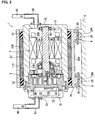
Fig. 2 is a cross-sectional view of the motor-driven compressor of the first embodiment; -
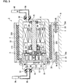
Fig. 3 is a cross-sectional view of a motor-driven compressor according to a second embodiment of the present invention; and -
Fig. 4 is a cross-sectional view of a modified example of a motor-driven compressor according to the present invention. - First and second embodiments of the present invention will now be described with reference to the drawings.
- Referring to
Fig. 1 , a motor-drivencompressor 1 of the first embodiment is applied to an air conditioner installed in a vehicle to adjust the temperature of a passenger compartment. In addition to the motor-drivencompressor 1, the air conditioner includes aswitch valve 91, a passenger compartmentexterior heat exchanger 92, anexpansion valve 93, and a passenger compartmentinterior heat exchanger 94. - As shown in
Fig. 2 , the motor-drivencompressor 1 includes acompressor mechanism 3, amotor mechanism 5, aninner housing 10, and anouter housing 20. Theinner housing 10 accommodates thecompressor mechanism 3 and themotor mechanism 5 in a sealed state. Theouter housing 20 accommodates theinner housing 10. - In the present embodiment, the
inner housing 10 includes afirst housing 11, which includes an open rear end (left end as viewed inFig. 2 ), and asecond housing 12, which closes the rear end of thefirst housing 11. Thecompressor mechanism 3 includes afixed scroll 3A, which is fixed to an innercircumferential surface 11B of thefirst housing 11, and amovable scroll 3B, which is arranged to face thefixed scroll 3A. Thefixed scroll 3A andmovable scroll 3B are engaged with each other and form acompression chamber 3C. Adrive shaft 5A is accommodated in thefirst housing 11. Thedrive shaft 5A includes a distal portion (right side as viewed inFig. 2 ) supported in a rotatable manner by a bearing 5B, and a proximal portion (left side as viewed inFig. 2 ) supported in a rotatable manner by a bearing 5C. - The
motor mechanism 5 is located closer to anend wall 11D of thefirst housing 11 than thecompressor mechanism 3. Astator 5D is fixed to the innercircumferential surface 11B of thefirst housing 11. A drive circuit (not shown) supplies thestator 5D with three-phase current. Arotor 5E is arranged in thestator 5D. Therotor 5E is fixed to thedrive shaft 5A. Therotor 5E is rotated and driven by the current supplied to thestator 5D. Thedrive shaft 5A,stator 5D, androtor 5E form themotor mechanism 5. - Referring to
Figs. 1 and2 , when themotor mechanism 5 rotates and actuates thecompressor mechanism 3, thecompressor mechanism 3 draws refrigerant into theinner housing 10 through asuction pipe 95 and compresses the refrigerant. Then, thecompressor mechanism 3 discharges the compressed refrigerant from theinner housing 10 through adischarge pipe 96. - Referring to
Fig. 1 , theswitch valve 91 is connected to the motor-drivencompressor 1 by thesuction pipe 95 and thedischarge pipe 96. Further, theswitch valve 91 is connected to the passenger compartmentexterior heat exchanger 92 by apipe 97 and the passenger compartmentinterior heat exchanger 94 by apipe 99. Theexpansion valve 93 is connected to the passenger compartmentexterior heat exchanger 92 by apipe 98A and the passenger compartmentinterior heat exchanger 94 by apipe 98B. - The
switch valve 91, which is controlled by a control unit installed in the vehicle, can switch communication states of pipes. When theswitch valve 91 communicates thedischarge pipe 96 andpipe 97, and communicates thesuction pipe 95 andpipe 99, the refrigerant discharged from the motor-drivencompressor 1 through thedischarge pipe 96 flows in direction D1 as shown inFig. 1 . When theswitch valve 91 communicates thedischarge pipe 96 andpipe 99, and communicates thesuction pipe 95 andpipe 97, the refrigerant discharged from the motor-drivencompressor 1 through thedischarge pipe 96 flows in direction D2 as shown inFig. 1 . - The passenger compartment
exterior heat exchanger 92 dissipates heat to or absorbs heat from the ambient air. The passenger compartmentinterior heat exchanger 94 dissipates heat to or absorbs heat from the air in the passenger compartment. The passenger compartmentexterior heat exchanger 92, the passenger compartmentinterior heat exchanger 94, and theexpansion valve 93 are known in the art and will not be illustrated or described in detail. - As shown in
Fig. 2 , theinner housing 10 includes a sealedcavity 10A, which accommodates thecompressor mechanism 3 andmotor mechanism 5 in a sealed state. Theinner housing 10 is generally cylindrical and elongated in the direction in which thecompressor mechanism 3 and themotor mechanism 5 are arranged. Theinner housing 10 may be formed from a single member or a plurality of members coupled to each other to define the sealedcavity 10A. To obtain the durability required for theinner housing 10 to endure the vibration and heat, which are generated from thecompressor mechanism 3 andmotor mechanism 5, and the high-temperature and high-pressure refrigerant, it is preferable that theinner housing 10 be formed from a metal, such as steel or aluminum. - The
compressor mechanism 3 and themotor mechanism 5 are fixed in the sealedcavity 10A by undergoing a known fastening process, such as shrinkage fitting, pressurized fitting, or bolt fastening. A fastening structure involving such a fastening process fixes thecompressor mechanism 3 and themotor mechanism 5 with high rigidity. However, it is difficult to attenuate vibration and noise generated by thecompressor mechanism 3 andmotor mechanism 5 with such a structure. As a result, the vibration and noise of thecompressor mechanism 3 andmotor mechanism 5 are easily transmitted to theinner housing 10. Heat is also easily transmitted from thecompressor mechanism 3 and themotor mechanism 5 to theinner housing 10. - A
suction port 15 extends through theend wall 11D of thefirst housing 11. Asuction coupling 50, which serves as an outer pipe, is fixed to thesuction port 15. A refrigerant supply passage is formed in the sealedcavity 10A between thesuction port 15 and thecompressor mechanism 3. - A
discharge chamber 3D is defined between thefirst housing 11 and thesecond housing 12. Thesecond housing 12 includes anend wall 12D through which adischarge port 16 extends. Adischarge coupling 60, which serves as an outer pipe, is fixed to thedischarge port 16. - The
suction coupling 50 and dischargecoupling 60 are known pipe couplings. Thesuction pipe 95 is coupled to thesuction coupling 50. Thedischarge pipe 96 is coupled to thedischarge coupling 60. - The
outer housing 20 is generally cylindrical and elongated in the direction in which thecompressor mechanism 3 and themotor mechanism 5 are arranged. Theouter housing 20, which accommodates theinner housing 10, may be formed from a metal, such as steel or aluminum, a resin, or a fiber reinforced resin. Theouter housing 20 includes two open ends in the longitudinal direction. Thesuction coupling 50 and thedischarge coupling 60 respectively project outward from the two open ends. Thesuction coupling 50 and thedischarge coupling 60 are not in contact with theouter housing 20. - The
outer housing 20 includes an outer wall surface 20C. Block-shaped mountingportions 29, which can be mounted to other members, are formed on the outer wall surface 20C. The mountingportions 29 project outward in the radial direction of theouter housing 20. Aninsertion hole 29A extends through each mountingportion 29 parallel to the longitudinal direction of theouter housing 20. A plurality ofsupports 8 project from a mountingobject 9, such as a frame or engine of the vehicle. The mountingportions 29 are engaged with thesupports 8.Bolts 9A are fastened to the mountingportions 29 and supports 8. This fixes the motor-drivencompressor 1 to the mountingobject 9. The fastening structure of the mountingportions 29, supports 8, andbolts 9A fix theouter housing 20 to the mountingobject 9 with high rigidity. However, it is difficult to attenuate the vibration and noise transmitted from theouter housing 20 to the mountingobject 9. - In the present embodiment, first
intermediate members inner housing 10 and theouter housing 20. - The first
intermediate members intermediate members 31 have an anti-vibration property and is formed from an anti-vibration material, such as rubber, elastomer, resin, fiber reinforced resin, or silicon gel. In the present embodiment, the firstintermediate members 31 are rubber annular bodies, or so-called O-rings. The firstintermediate members 31 are arranged at the two longitudinal ends of theinner housing 10 andouter housing 20 in a compressed and deformed state between aninner wall surface 20B of theouter housing 20 and anouter wall surface 11C of thefirst housing 11. Thus, the firstintermediate members 31 support theinner housing 10 in theouter housing 20. - The first
intermediate member 32 has a thermal insulation property and is formed from a thermal insulation material, such as fiber mass of glass wool or the like, a foam material, cellulose fibers, or a vacuum insulation material. In the present embodiment, the firstintermediate member 32 is a thick sheet of glass wool. The firstintermediate member 32, which is wound around theouter wall surface 11C of thefirst housing 11, fills the void betweeninner wall surface 20B of theouter housing 20 and theouter wall surface 11C of thefirst housing 11. Thus, the firstintermediate member 32 supports theinner housing 10 in theouter housing 20 in a supplemental manner. The firstintermediate member 32 is sandwiched between the firstintermediate members 31 and not exposed to the exterior from the two longitudinal ends of theinner housing 10 andouter housing 20. - The air conditioner, to which the motor-driven
compressor 1 of the first embodiment is applied, adjusts the temperature of the passenger compartment as described below. - Referring to
Fig. 1 , when cooling the passenger compartment, theswitch valve 91 communicates thedischarge pipe 96 andpipe 97, and communicates thesuction pipe 95 andpipe 99. As a result, the high-temperature and high-pressure refrigerant compressed by thecompressor mechanism 3 flows in direction D1. The refrigerant dissipates heat into the ambient air and liquefies at the passenger compartmentexterior heat exchanger 92. Then, the pressure of the refrigerant is decreased at theexpansion valve 93. Subsequently, the refrigerant absorbs heat from the air in the passenger compartment and vaporizes at the passenger compartmentinterior heat exchanger 94. This cools the air in the passenger compartment. The refrigerant then returns to the motor-drivencompressor 1 via thepipe 99, theswitch valve 91, and thesuction pipe 95. - When heating the passenger compartment, the
switch valve 91 communicates thedischarge pipe 96 andpipe 99, and communicates thesuction pipe 95 andpipe 97. As a result, the high-temperature and high-pressure refrigerant compressed by thecompressor mechanism 3 flows in direction D2. The refrigerant dissipates heat into the air in the passenger compartment and liquefies at the passenger compartmentinterior heat exchanger 94. This heats the air in the passenger compartment. Then, the pressure of the refrigerant is decreased at theexpansion valve 93. Subsequently, the refrigerant absorbs heat from the ambient air and vaporizes at the passenger compartmentexterior heat exchanger 92. The refrigerant then returns to the motor-drivencompressor 1 via thepipe 97, theswitch valve 91, and thesuction pipe 95. - In the motor-driven
compressor 1 of the first embodiment, thecompressor mechanism 3 andmotor mechanism 5 are fixed to theinner housing 10 with high rigidity. Further, the mountingportions 29, thesupports 8, and thebolts 9A fix theouter housing 20 to the mountingobject 9 with high rigidity. Thus, if the transmission of vibration and noise cannot be suppressed between theinner housing 10 and theouter housing 20, the vibration and noise from thecompressor mechanism 3 andmotor mechanism 5 would be transmitted from theinner housing 10 andouter housing 20 to the mountingobject 9 without being attenuated. This may adversely affect comfort in the environment of the passenger compartment. Further, if the transmission of heat between theinner housing 10 andouter housing 20 cannot be suppressed, the heat of the high-temperature and high-pressure refrigerant compressed by thecompressor mechanism 3 would be dissipated to the exterior through theouter housing 20. - In this regard, the motor-driven
compressor 1 of the first embodiment includes the firstintermediate members inner housing 10 and theouter housing 20. Since the firstintermediate members 31 have an anti-vibration property, the transmission of vibration and noise, generated by thecompressor mechanism 3 andmotor mechanism 5, from theinner housing 10 to theouter housing 20 and mountingobject 9 is suppressed. The firstintermediate members 32, which are formed from glass wool, also suppress the transmission of vibration and noise from theinner housing 10 to theouter housing 20. - Further, the first
intermediate members 32 have a thermal insulation property. Thus, the heat of the high-temperature and high-pressure refrigerant compressed by thecompressor mechanism 3 is not transmitted from theinner housing 10 to the firstintermediate member 32 and theouter housing 20. Further, the firstintermediate members 31, which are formed from rubber, also suppress the transmission of the heat of the refrigerant. Thus, the motor-drivencompressor 1 prevents the heat from decreasing in the drawn in refrigerant and the discharged refrigerant. Accordingly, when the air conditioner functions as a heat pump and heats the passenger compartment, the temperature of the refrigerant flowing to the passenger compartmentinterior heat exchanger 94 can be increased. As a result, the passenger compartmentinterior heat exchanger 94 effectively dissipates heat to the air in the passenger compartment and exhibits sufficient heating performance. - The motor-driven
compressor 1 of the first embodiment suppresses the transmission of vibration and noise to the exterior and exhibits sufficient heating performance when used in the heat pump. - The structure of the first embodiment also has the advantages described below.
- The
inner housing 10 accommodates thecompressor mechanism 3 and themotor mechanism 5 in a sealed state. This allows theouter housing 20 to have a simple shape. Further, the firstintermediate members inner housing 10 and theouter housing 20. Thus, the mountingportions 29 of theouter housing 20 and the structure that fastens thecompressor mechanism 3 andmotor mechanism 5 to theinner housing 10 do not have to be provided with an anti-vibration property. This simplifies the structure of such parts. - The
suction coupling 50 and thedischarge coupling 60 respectively coupled to thesuction port 15 and thedischarge port 16 are fixed to theinner housing 10 without contacting theouter housing 20. Thus, thesuction coupling 50 and dischargecoupling 60 do not transmit vibration and noise from thecompressor mechanism 3 andmotor mechanism 5 to theouter housing 20 and its exterior. Thesuction coupling 50 and dischargecoupling 60 also do not transmit the heat of the refrigerant to theouter housing 20. This ensures that the motor-drivencompressor 1 has the advantages of the present invention. - In the present example, the intermediate members arranged between the
inner housing 10 and theouter housing 20 are the firstintermediate members 31, which have an anti-vibration property, and the firstintermediate member 32, which has a thermal insulation property. This increases the types of materials that can be used for the firstintermediate members - The first
intermediate member 32, which is formed from a thermal insulation material, is arranged at the inner side between theinner housing 10 and theouter housing 20, and the firstintermediate members 31, which are formed from an anti-vibration material, are arranged at the outer side between theinner housing 10 and theouter housing 20. Thus, the firstintermediate members 31 closes the void between theinner housing 10 and theouter housing 20 and protects the firstintermediate member 32 located between theinner housing 10 andouter housing 20. This prevents deterioration and loss of the material forming the first intermediate member 32 (e.g., glass wool) that may be caused by wind and rain. - The
outer housing 20 has a simple cylindrical shape. This lowers the manufacturing cost. Further, theinner housing 10 can easily be accommodated in theouter housing 20. This simplifies the assembling of the motor-driven compressor. - A motor-driven compressor 2 of a second embodiment uses a first
intermediate member 33 in lieu of the firstintermediate members intermediate members 34 are arranged between theinner housing 10 andsuction coupling 50 and theinner housing 10 and dischargecoupling 60. Otherwise, the structure of the motor-driven compressor 2 is the same as that of the motor-drivencompressor 1 of the first embodiment. Like or same reference numerals are given to those components that are the same as the corresponding components of the first embodiment. - The first
intermediate member 33 is formed from a material having anti-vibration and thermal insulation properties. In the present example, the firstintermediate member 33 is a cylinder having a thick wall of glass wool. The firstintermediate member 33 fills the void between theinner wall surface 20B of theouter housing 20 and theouter wall surface 11C of thefirst housing 11. - The second
intermediate members 34 are formed from a material having either one of an anti-vibration property and a thermal insulation property. In the present example, the secondintermediate members 34 are rubber annular bodies having an anti-vibration property. - The motor-driven compressor 2 of the second embodiment has the same advantages as the first embodiment.
- The first
intermediate member 33 is formed from a single member having anti-vibration and thermal insulation properties. Thus, in comparison to when using the firstintermediate members - The second
intermediate member 34, which has an anti-vibration property, suppresses the transmission of vibration and noise from thecompressor mechanism 3 andmotor mechanism 5 between theinner housing 10 andsuction coupling 50, and between theinner housing 10 and dischargecoupling 60. The secondintermediate members 34 suppress the transmission of heat from the refrigerant. Thus, in comparison with when thesuction coupling 50 and dischargecoupling 60 are directly fixed to theinner housing 10, the transmission of refrigerant heat is suppressed from theinner housing 10 via thesuction coupling 50 and dischargecoupling 60 to the exterior. As a result, the motor-driven compressor 2 has the advantages of the present invention. - It should be apparent to those skilled in the art that the present invention may be embodied in many other specific forms without departing from the spirit or scope of the invention. Particularly, it should be understood that the present invention may be embodied in the following forms.
- The
outer housing 20 does not have to be cylindrical and include two open ends. Theouter housing 20 may encase the entireinner housing 10 and include only one open end. - The fastening structure and shapes of the mounting
portions 29, thesupports 8, and thebolts 9A are not limited to those of the above embodiments. Any structure can be employed as long as the mountingportions 29 can fix the motor-drivencompressor 1 to the mountingobject 9. - In the first embodiment, the second
intermediate member 34 of the second embodiment can be arranged between thesuction port 15 andsuction coupling 50 and/or between thedischarge port 16 and thedischarge coupling 60. Further, as shown inFig. 4 , the motor-drivencompressor 1 may include anintermediate member 35, which integrates one of the firstintermediate members 31 of the first embodiment with one of the secondintermediate members 34 of the second embodiment. In this case, the part of theinner housing 10 that is not covered by theouter housing 20 is covered by theintermediate member 35. Theintermediate member 35, which is formed from rubber, increases the covered region of theinner housing 10. This improves the thermal insulation effect. As a result, dissipation of the refrigerant heat from theinner housing 10 to the exterior is further suppressed. - In the second embodiment, the second
intermediate member 34 may be arranged only between thesuction port 15 andsuction coupling 50 or only between thedischarge port 16 and dischargecoupling 60. Further, theintermediate member 33 may be formed integrally with the secondintermediate member 34. - The
compressor mechanism 3 is not limited to a scroll type and may be of a reciprocating type, a vane type, or any other known compression type. - The present examples and embodiments are to be considered as illustrative and not restrictive, and the invention is not to be limited to the details given herein, but may be modified within the scope and equivalence of the appended claims.
- A motor-driven compressor that suppresses the transmission of vibration and noise to the exterior, while obtaining heating performance that is sufficient for use in a heat pump. The motor-driven compressor includes a compressor mechanism, which compresses a refrigerant, and a motor mechanism, which actuates the compressor mechanism. The motor-driven compressor further includes an inner housing, which accommodates the compressor mechanism and the motor mechanism in a sealed state, and an outer housing, which accommodates the inner housing. The outer housing includes a mounting portion that can be mounted to another member. A first intermediate member is arranged between the inner housing and the outer housing. The first intermediate member includes anti-vibration and thermal insulation properties.
Claims (7)
- A motor-driven compressor (1) comprising:a compressor mechanism (3) that compresses a refrigerant; and a motor mechanism (5) that actuates the compressor mechanism (3),the motor-driven compressor (1) being characterized in that:the motor-driven compressor (1) further comprising:an inner housing (10) that accommodates the compressor mechanism (3) and the motor mechanism (5) in a sealed state;an outer housing (20) that accommodates the inner housing (10), wherein the outer housing (20) includes a mounting portion (29) that can be mounted to another member; anda first intermediate member (31, 32) arranged between the inner housing (10) and the outer housing(20), wherein the first intermediate member (31, 32) includes anti-vibration and thermal insulation properties.
- The motor-driven compressor according to claim 1, characterized in that the inner housing (10) includes a suction port (15), which draws the refrigerant into the compressor mechanism (3), and a discharge port (16), which discharges the refrigerant from the compressor mechanism (3),
wherein outer pipes (50, 60) respectively coupled to the suction port (15) and the discharge port (16), and each of the outer pipes (50, 60) is fixed to the inner housing (10) without contacting the outer housing (20). - The motor-driven compressor according to claim 2, characterized in that the motor-driven compressor further comprising a second intermediate member (34) arranged between at least one of the suction port (15) and discharge port (16) and the corresponding outer pipe (50, 60), wherein the second intermediate member (34) has at least one of an anti-vibration property and a thermal insulation property.
- The motor-driven compressor according to claim 3, characterized in that the first intermediate member (31, 32) is integral with the second intermediate member (34).
- The motor-driven compressor according to any one of claims 1 to 4, characterized in that the first intermediate member (31, 32) is formed from an anti-vibration material (31) having an anti-vibration property and a thermal insulation material (32) having a thermal insulation property.
- The motor-driven compressor according to claim 5, characterized in that the thermal insulation material (32) is sandwiched by the anti-vibration material (31) and unexposed to the exterior.
- The motor-driven compressor according to claim 1, characterized in that the outer housing (20) is cylindrical.
Applications Claiming Priority (1)
| Application Number | Priority Date | Filing Date | Title |
|---|---|---|---|
| JP2011076998A JP5637048B2 (en) | 2011-03-31 | 2011-03-31 | Electric compressor |
Publications (3)
| Publication Number | Publication Date |
|---|---|
| EP2505777A2 true EP2505777A2 (en) | 2012-10-03 |
| EP2505777A3 EP2505777A3 (en) | 2016-12-21 |
| EP2505777B1 EP2505777B1 (en) | 2019-12-04 |
Family
ID=45936955
Family Applications (1)
| Application Number | Title | Priority Date | Filing Date |
|---|---|---|---|
| EP12161685.8A Active EP2505777B1 (en) | 2011-03-31 | 2012-03-28 | Motor-driven compressor |
Country Status (5)
| Country | Link |
|---|---|
| US (1) | US9181950B2 (en) |
| EP (1) | EP2505777B1 (en) |
| JP (1) | JP5637048B2 (en) |
| KR (1) | KR101363170B1 (en) |
| CN (1) | CN102734172B (en) |
Cited By (1)
| Publication number | Priority date | Publication date | Assignee | Title |
|---|---|---|---|---|
| GB2514638A (en) * | 2013-03-13 | 2014-12-03 | Agilent Technologies Inc | Vibration/noise management in a scroll compressor |
Families Citing this family (20)
| Publication number | Priority date | Publication date | Assignee | Title |
|---|---|---|---|---|
| ES2607379T3 (en) * | 2012-08-24 | 2017-03-31 | Lg Electronics Inc. | Alternative compressor |
| CN103016346A (en) * | 2012-12-15 | 2013-04-03 | 合肥同智机电控制技术股份有限公司 | Electric compressor assembly for automobile air conditioner |
| ITFI20130118A1 (en) * | 2013-05-21 | 2014-11-22 | Nuovo Pignone Srl | "COMPRESSOR WITH A THERMAL SHIELD AND METHODS OF OPERATION" |
| JP6204138B2 (en) * | 2013-09-30 | 2017-09-27 | ミネベアミツミ株式会社 | Coolant injection device |
| JP6094497B2 (en) * | 2014-01-20 | 2017-03-15 | 株式会社豊田自動織機 | Electric compressor and method for manufacturing electric compressor |
| KR102366701B1 (en) | 2014-10-22 | 2022-02-22 | 엘지디스플레이 주식회사 | Flexible thin film transistor substrate and flexible organic light emitting display device |
| JP6460236B2 (en) * | 2015-07-03 | 2019-01-30 | 三菱電機株式会社 | Heat pump equipment |
| WO2017006387A1 (en) * | 2015-07-03 | 2017-01-12 | 三菱電機株式会社 | Heat pump device |
| JP2017066943A (en) * | 2015-09-29 | 2017-04-06 | 株式会社豊田自動織機 | Compressor |
| CN107867323B (en) | 2016-09-28 | 2019-11-22 | 比亚迪股份有限公司 | Motor oil pump assembly, steering system and vehicle |
| CN107869439B (en) * | 2016-09-28 | 2019-11-08 | 比亚迪股份有限公司 | Motor oil pump assembly, steering system and vehicle |
| US20190226486A1 (en) * | 2016-11-21 | 2019-07-25 | Ihi Corporation | Electric compressor |
| JP2018204493A (en) * | 2017-06-01 | 2018-12-27 | サンデン・オートモーティブコンポーネント株式会社 | Compressor |
| JP7005298B2 (en) | 2017-11-09 | 2022-01-21 | 三菱重工サーマルシステムズ株式会社 | Electric compressor for vehicles |
| KR102014376B1 (en) | 2018-06-25 | 2019-08-26 | 클러스터엘앤지(주) | Boil-off gas compressor for lng fueled ship |
| EP4050212B1 (en) * | 2019-12-06 | 2026-05-06 | Daikin Industries, Ltd. | Compressor and compressor unit |
| CN112177950B (en) * | 2020-08-27 | 2021-12-10 | 蚌埠翔云压缩机制造有限公司 | Circulating centrifugal gas compressor |
| JP7728650B2 (en) * | 2021-03-29 | 2025-08-25 | 三菱重工サーマルシステムズ株式会社 | Scroll fluid machinery |
| CN116191739A (en) * | 2021-11-29 | 2023-05-30 | 宁波奥克斯电气股份有限公司 | A kind of motor and air conditioner |
| DE102022111378A1 (en) * | 2022-05-06 | 2023-11-09 | OET GmbH | Displacement machine based on the spiral principle |
Citations (1)
| Publication number | Priority date | Publication date | Assignee | Title |
|---|---|---|---|---|
| JPH11294365A (en) | 1998-04-09 | 1999-10-26 | Sharp Corp | Hermetic compressor |
Family Cites Families (26)
| Publication number | Priority date | Publication date | Assignee | Title |
|---|---|---|---|---|
| JPS61218784A (en) * | 1985-03-25 | 1986-09-29 | Toshiba Corp | Refrigeration cycle apparatus |
| US4734323A (en) * | 1986-04-22 | 1988-03-29 | Toyoda Gosei Co., Ltd. | Vibration damping soundproof sheets for use in vehicles |
| JPS6326786U (en) * | 1986-08-06 | 1988-02-22 | ||
| JPH01106697U (en) | 1988-01-06 | 1989-07-18 | ||
| JPH01145614U (en) * | 1988-03-17 | 1989-10-06 | ||
| JPH0565876A (en) * | 1991-09-06 | 1993-03-19 | Toshiba Corp | Compressor unit |
| US5272285A (en) * | 1992-08-20 | 1993-12-21 | Scott Mfg., Inc. | Sound attenuating machinery cover |
| JPH06288353A (en) | 1993-04-02 | 1994-10-11 | Mitsubishi Heavy Ind Ltd | Elastic suspension device for horizontally installed compressor |
| US5997258A (en) * | 1994-05-31 | 1999-12-07 | Bristol Compressors, Inc. | Low noise refrigerant compressor having closed shells and sound absorbing spacers |
| JP3102292B2 (en) | 1995-03-23 | 2000-10-23 | 株式会社豊田自動織機製作所 | Reciprocating piston compressor |
| KR100314037B1 (en) * | 1999-12-29 | 2001-11-15 | 구자홍 | Structure for preventing gas-heating in compressor |
| US6264446B1 (en) * | 2000-02-02 | 2001-07-24 | Copeland Corporation | Horizontal scroll compressor |
| JP2002070743A (en) * | 2000-08-29 | 2002-03-08 | Sanden Corp | Motor-driven compressor for refrigerant compression |
| JP2002276554A (en) | 2001-03-14 | 2002-09-25 | Matsushita Electric Ind Co Ltd | Compressor with built-in electric motor mounted on mobile car engine |
| JP2004143975A (en) * | 2002-10-23 | 2004-05-20 | Hitachi Home & Life Solutions Inc | Compressor soundproofing |
| JP4259126B2 (en) | 2003-01-29 | 2009-04-30 | ダイキン工業株式会社 | Rotary compressor |
| JP2005133707A (en) * | 2003-10-10 | 2005-05-26 | Matsushita Electric Ind Co Ltd | Hermetic compressor |
| US7398855B2 (en) * | 2004-05-14 | 2008-07-15 | Emerson Climate Technologies, Inc. | Compressor sound attenuation enclosure |
| JP2007016601A (en) | 2005-07-05 | 2007-01-25 | Calsonic Compressor Inc | Gas compressor |
| JP2008169812A (en) * | 2007-01-15 | 2008-07-24 | Daikin Ind Ltd | Sound insulation sheet |
| JP2009014228A (en) | 2007-07-03 | 2009-01-22 | Daikin Ind Ltd | Refrigeration equipment |
| JP2009062956A (en) * | 2007-09-10 | 2009-03-26 | Panasonic Corp | Hermetic compressor |
| JP2009103100A (en) | 2007-10-25 | 2009-05-14 | Denso Corp | Electric compressor for vehicles |
| JP2009138697A (en) | 2007-12-10 | 2009-06-25 | Denso Corp | Compressor for vehicle |
| US8079443B2 (en) * | 2008-01-07 | 2011-12-20 | Pelzer Acoustic Products Gmbh | Aircraft trim panel with integrated adjustable acoustic properties |
| JP2009221969A (en) | 2008-03-17 | 2009-10-01 | Calsonic Kansei Corp | Compressor |
-
2011
- 2011-03-31 JP JP2011076998A patent/JP5637048B2/en active Active
-
2012
- 2012-03-26 KR KR1020120030518A patent/KR101363170B1/en active Active
- 2012-03-27 CN CN201210084818.7A patent/CN102734172B/en active Active
- 2012-03-27 US US13/431,508 patent/US9181950B2/en active Active
- 2012-03-28 EP EP12161685.8A patent/EP2505777B1/en active Active
Patent Citations (1)
| Publication number | Priority date | Publication date | Assignee | Title |
|---|---|---|---|---|
| JPH11294365A (en) | 1998-04-09 | 1999-10-26 | Sharp Corp | Hermetic compressor |
Cited By (3)
| Publication number | Priority date | Publication date | Assignee | Title |
|---|---|---|---|---|
| GB2514638A (en) * | 2013-03-13 | 2014-12-03 | Agilent Technologies Inc | Vibration/noise management in a scroll compressor |
| US9435339B2 (en) | 2013-03-13 | 2016-09-06 | Agilent Technologies, Inc. | Vibration/noise management in a scroll compressor |
| GB2514638B (en) * | 2013-03-13 | 2020-04-22 | Agilent Technologies Inc | Vibration/noise management in a scroll compressor |
Also Published As
| Publication number | Publication date |
|---|---|
| KR101363170B1 (en) | 2014-02-13 |
| US9181950B2 (en) | 2015-11-10 |
| JP5637048B2 (en) | 2014-12-10 |
| JP2012211530A (en) | 2012-11-01 |
| EP2505777B1 (en) | 2019-12-04 |
| KR20120112083A (en) | 2012-10-11 |
| US20120251358A1 (en) | 2012-10-04 |
| CN102734172B (en) | 2015-01-21 |
| CN102734172A (en) | 2012-10-17 |
| EP2505777A3 (en) | 2016-12-21 |
Similar Documents
| Publication | Publication Date | Title |
|---|---|---|
| EP2505777B1 (en) | Motor-driven compressor | |
| JP5403004B2 (en) | Electric compressor | |
| US9068458B2 (en) | Shock protector for a compressor's drive circuit | |
| EP2505775A2 (en) | Motor-driven compressor | |
| WO2018155001A1 (en) | Compressor and refrigeration cycle device | |
| EP1201927A2 (en) | Vacuum pump | |
| CN103108788A (en) | Brake operating units for motor vehicle braking systems and motor-pump assemblies for supplying vacuum to brake operating units for motor vehicle braking systems | |
| JP4606272B2 (en) | Cooling system electric compressor | |
| WO2026094851A1 (en) | Vehicle air conditioning system | |
| US9316226B2 (en) | Gas compressor for reducing oscillation in a housing thereof | |
| JP2009085373A (en) | Piping joint structure and vehicle refrigeration cycle apparatus | |
| CN102656034A (en) | Motor vehicle air conditioning circuits including volume expansion chambers | |
| KR102688672B1 (en) | Compressor | |
| KR100429462B1 (en) | The structure for decreasing noise of compressor | |
| JP2004051021A (en) | How to mount a compressor on a vehicle | |
| KR0128916Y1 (en) | Low noise refrigerator | |
| CN118030528A (en) | compressor | |
| WO2021210279A1 (en) | Refrigeration cycle device | |
| JP2011231711A (en) | Electric compressor |
Legal Events
| Date | Code | Title | Description |
|---|---|---|---|
| PUAI | Public reference made under article 153(3) epc to a published international application that has entered the european phase |
Free format text: ORIGINAL CODE: 0009012 |
|
| 17P | Request for examination filed |
Effective date: 20120328 |
|
| AK | Designated contracting states |
Kind code of ref document: A2 Designated state(s): AL AT BE BG CH CY CZ DE DK EE ES FI FR GB GR HR HU IE IS IT LI LT LU LV MC MK MT NL NO PL PT RO RS SE SI SK SM TR |
|
| AX | Request for extension of the european patent |
Extension state: BA ME |
|
| PUAL | Search report despatched |
Free format text: ORIGINAL CODE: 0009013 |
|
| AK | Designated contracting states |
Kind code of ref document: A3 Designated state(s): AL AT BE BG CH CY CZ DE DK EE ES FI FR GB GR HR HU IE IS IT LI LT LU LV MC MK MT NL NO PL PT RO RS SE SI SK SM TR |
|
| AX | Request for extension of the european patent |
Extension state: BA ME |
|
| RIC1 | Information provided on ipc code assigned before grant |
Ipc: F04C 23/00 20060101ALI20161114BHEP Ipc: F04C 18/02 20060101ALI20161114BHEP Ipc: F01C 21/10 20060101AFI20161114BHEP |
|
| GRAP | Despatch of communication of intention to grant a patent |
Free format text: ORIGINAL CODE: EPIDOSNIGR1 |
|
| STAA | Information on the status of an ep patent application or granted ep patent |
Free format text: STATUS: GRANT OF PATENT IS INTENDED |
|
| INTG | Intention to grant announced |
Effective date: 20190619 |
|
| GRAS | Grant fee paid |
Free format text: ORIGINAL CODE: EPIDOSNIGR3 |
|
| GRAA | (expected) grant |
Free format text: ORIGINAL CODE: 0009210 |
|
| STAA | Information on the status of an ep patent application or granted ep patent |
Free format text: STATUS: THE PATENT HAS BEEN GRANTED |
|
| AK | Designated contracting states |
Kind code of ref document: B1 Designated state(s): AL AT BE BG CH CY CZ DE DK EE ES FI FR GB GR HR HU IE IS IT LI LT LU LV MC MK MT NL NO PL PT RO RS SE SI SK SM TR |
|
| REG | Reference to a national code |
Ref country code: GB Ref legal event code: FG4D |
|
| REG | Reference to a national code |
Ref country code: CH Ref legal event code: EP |
|
| REG | Reference to a national code |
Ref country code: AT Ref legal event code: REF Ref document number: 1209648 Country of ref document: AT Kind code of ref document: T Effective date: 20191215 |
|
| REG | Reference to a national code |
Ref country code: DE Ref legal event code: R096 Ref document number: 602012066135 Country of ref document: DE |
|
| REG | Reference to a national code |
Ref country code: IE Ref legal event code: FG4D |
|
| REG | Reference to a national code |
Ref country code: NL Ref legal event code: MP Effective date: 20191204 |
|
| REG | Reference to a national code |
Ref country code: LT Ref legal event code: MG4D |
|
| PG25 | Lapsed in a contracting state [announced via postgrant information from national office to epo] |
Ref country code: LT Free format text: LAPSE BECAUSE OF FAILURE TO SUBMIT A TRANSLATION OF THE DESCRIPTION OR TO PAY THE FEE WITHIN THE PRESCRIBED TIME-LIMIT Effective date: 20191204 Ref country code: ES Free format text: LAPSE BECAUSE OF FAILURE TO SUBMIT A TRANSLATION OF THE DESCRIPTION OR TO PAY THE FEE WITHIN THE PRESCRIBED TIME-LIMIT Effective date: 20191204 Ref country code: NO Free format text: LAPSE BECAUSE OF FAILURE TO SUBMIT A TRANSLATION OF THE DESCRIPTION OR TO PAY THE FEE WITHIN THE PRESCRIBED TIME-LIMIT Effective date: 20200304 Ref country code: GR Free format text: LAPSE BECAUSE OF FAILURE TO SUBMIT A TRANSLATION OF THE DESCRIPTION OR TO PAY THE FEE WITHIN THE PRESCRIBED TIME-LIMIT Effective date: 20200305 Ref country code: LV Free format text: LAPSE BECAUSE OF FAILURE TO SUBMIT A TRANSLATION OF THE DESCRIPTION OR TO PAY THE FEE WITHIN THE PRESCRIBED TIME-LIMIT Effective date: 20191204 Ref country code: SE Free format text: LAPSE BECAUSE OF FAILURE TO SUBMIT A TRANSLATION OF THE DESCRIPTION OR TO PAY THE FEE WITHIN THE PRESCRIBED TIME-LIMIT Effective date: 20191204 Ref country code: FI Free format text: LAPSE BECAUSE OF FAILURE TO SUBMIT A TRANSLATION OF THE DESCRIPTION OR TO PAY THE FEE WITHIN THE PRESCRIBED TIME-LIMIT Effective date: 20191204 Ref country code: BG Free format text: LAPSE BECAUSE OF FAILURE TO SUBMIT A TRANSLATION OF THE DESCRIPTION OR TO PAY THE FEE WITHIN THE PRESCRIBED TIME-LIMIT Effective date: 20200304 |
|
| PG25 | Lapsed in a contracting state [announced via postgrant information from national office to epo] |
Ref country code: RS Free format text: LAPSE BECAUSE OF FAILURE TO SUBMIT A TRANSLATION OF THE DESCRIPTION OR TO PAY THE FEE WITHIN THE PRESCRIBED TIME-LIMIT Effective date: 20191204 Ref country code: HR Free format text: LAPSE BECAUSE OF FAILURE TO SUBMIT A TRANSLATION OF THE DESCRIPTION OR TO PAY THE FEE WITHIN THE PRESCRIBED TIME-LIMIT Effective date: 20191204 |
|
| PG25 | Lapsed in a contracting state [announced via postgrant information from national office to epo] |
Ref country code: AL Free format text: LAPSE BECAUSE OF FAILURE TO SUBMIT A TRANSLATION OF THE DESCRIPTION OR TO PAY THE FEE WITHIN THE PRESCRIBED TIME-LIMIT Effective date: 20191204 |
|
| PG25 | Lapsed in a contracting state [announced via postgrant information from national office to epo] |
Ref country code: EE Free format text: LAPSE BECAUSE OF FAILURE TO SUBMIT A TRANSLATION OF THE DESCRIPTION OR TO PAY THE FEE WITHIN THE PRESCRIBED TIME-LIMIT Effective date: 20191204 Ref country code: PT Free format text: LAPSE BECAUSE OF FAILURE TO SUBMIT A TRANSLATION OF THE DESCRIPTION OR TO PAY THE FEE WITHIN THE PRESCRIBED TIME-LIMIT Effective date: 20200429 Ref country code: CZ Free format text: LAPSE BECAUSE OF FAILURE TO SUBMIT A TRANSLATION OF THE DESCRIPTION OR TO PAY THE FEE WITHIN THE PRESCRIBED TIME-LIMIT Effective date: 20191204 Ref country code: NL Free format text: LAPSE BECAUSE OF FAILURE TO SUBMIT A TRANSLATION OF THE DESCRIPTION OR TO PAY THE FEE WITHIN THE PRESCRIBED TIME-LIMIT Effective date: 20191204 Ref country code: RO Free format text: LAPSE BECAUSE OF FAILURE TO SUBMIT A TRANSLATION OF THE DESCRIPTION OR TO PAY THE FEE WITHIN THE PRESCRIBED TIME-LIMIT Effective date: 20191204 |
|
| PG25 | Lapsed in a contracting state [announced via postgrant information from national office to epo] |
Ref country code: SM Free format text: LAPSE BECAUSE OF FAILURE TO SUBMIT A TRANSLATION OF THE DESCRIPTION OR TO PAY THE FEE WITHIN THE PRESCRIBED TIME-LIMIT Effective date: 20191204 Ref country code: IS Free format text: LAPSE BECAUSE OF FAILURE TO SUBMIT A TRANSLATION OF THE DESCRIPTION OR TO PAY THE FEE WITHIN THE PRESCRIBED TIME-LIMIT Effective date: 20200404 Ref country code: SK Free format text: LAPSE BECAUSE OF FAILURE TO SUBMIT A TRANSLATION OF THE DESCRIPTION OR TO PAY THE FEE WITHIN THE PRESCRIBED TIME-LIMIT Effective date: 20191204 |
|
| REG | Reference to a national code |
Ref country code: DE Ref legal event code: R097 Ref document number: 602012066135 Country of ref document: DE |
|
| REG | Reference to a national code |
Ref country code: AT Ref legal event code: MK05 Ref document number: 1209648 Country of ref document: AT Kind code of ref document: T Effective date: 20191204 |
|
| PLBE | No opposition filed within time limit |
Free format text: ORIGINAL CODE: 0009261 |
|
| STAA | Information on the status of an ep patent application or granted ep patent |
Free format text: STATUS: NO OPPOSITION FILED WITHIN TIME LIMIT |
|
| PG25 | Lapsed in a contracting state [announced via postgrant information from national office to epo] |
Ref country code: MC Free format text: LAPSE BECAUSE OF FAILURE TO SUBMIT A TRANSLATION OF THE DESCRIPTION OR TO PAY THE FEE WITHIN THE PRESCRIBED TIME-LIMIT Effective date: 20191204 Ref country code: DK Free format text: LAPSE BECAUSE OF FAILURE TO SUBMIT A TRANSLATION OF THE DESCRIPTION OR TO PAY THE FEE WITHIN THE PRESCRIBED TIME-LIMIT Effective date: 20191204 |
|
| REG | Reference to a national code |
Ref country code: CH Ref legal event code: PL |
|
| 26N | No opposition filed |
Effective date: 20200907 |
|
| PG25 | Lapsed in a contracting state [announced via postgrant information from national office to epo] |
Ref country code: SI Free format text: LAPSE BECAUSE OF FAILURE TO SUBMIT A TRANSLATION OF THE DESCRIPTION OR TO PAY THE FEE WITHIN THE PRESCRIBED TIME-LIMIT Effective date: 20191204 Ref country code: PL Free format text: LAPSE BECAUSE OF FAILURE TO SUBMIT A TRANSLATION OF THE DESCRIPTION OR TO PAY THE FEE WITHIN THE PRESCRIBED TIME-LIMIT Effective date: 20191204 Ref country code: AT Free format text: LAPSE BECAUSE OF FAILURE TO SUBMIT A TRANSLATION OF THE DESCRIPTION OR TO PAY THE FEE WITHIN THE PRESCRIBED TIME-LIMIT Effective date: 20191204 |
|
| REG | Reference to a national code |
Ref country code: BE Ref legal event code: MM Effective date: 20200331 |
|
| PG25 | Lapsed in a contracting state [announced via postgrant information from national office to epo] |
Ref country code: LU Free format text: LAPSE BECAUSE OF NON-PAYMENT OF DUE FEES Effective date: 20200328 |
|
| PG25 | Lapsed in a contracting state [announced via postgrant information from national office to epo] |
Ref country code: IE Free format text: LAPSE BECAUSE OF NON-PAYMENT OF DUE FEES Effective date: 20200328 Ref country code: LI Free format text: LAPSE BECAUSE OF NON-PAYMENT OF DUE FEES Effective date: 20200331 Ref country code: CH Free format text: LAPSE BECAUSE OF NON-PAYMENT OF DUE FEES Effective date: 20200331 Ref country code: FR Free format text: LAPSE BECAUSE OF NON-PAYMENT OF DUE FEES Effective date: 20200331 Ref country code: IT Free format text: LAPSE BECAUSE OF FAILURE TO SUBMIT A TRANSLATION OF THE DESCRIPTION OR TO PAY THE FEE WITHIN THE PRESCRIBED TIME-LIMIT Effective date: 20191204 |
|
| PG25 | Lapsed in a contracting state [announced via postgrant information from national office to epo] |
Ref country code: BE Free format text: LAPSE BECAUSE OF NON-PAYMENT OF DUE FEES Effective date: 20200331 |
|
| GBPC | Gb: european patent ceased through non-payment of renewal fee |
Effective date: 20200328 |
|
| PG25 | Lapsed in a contracting state [announced via postgrant information from national office to epo] |
Ref country code: GB Free format text: LAPSE BECAUSE OF NON-PAYMENT OF DUE FEES Effective date: 20200328 |
|
| PG25 | Lapsed in a contracting state [announced via postgrant information from national office to epo] |
Ref country code: TR Free format text: LAPSE BECAUSE OF FAILURE TO SUBMIT A TRANSLATION OF THE DESCRIPTION OR TO PAY THE FEE WITHIN THE PRESCRIBED TIME-LIMIT Effective date: 20191204 Ref country code: MT Free format text: LAPSE BECAUSE OF FAILURE TO SUBMIT A TRANSLATION OF THE DESCRIPTION OR TO PAY THE FEE WITHIN THE PRESCRIBED TIME-LIMIT Effective date: 20191204 Ref country code: CY Free format text: LAPSE BECAUSE OF FAILURE TO SUBMIT A TRANSLATION OF THE DESCRIPTION OR TO PAY THE FEE WITHIN THE PRESCRIBED TIME-LIMIT Effective date: 20191204 |
|
| PG25 | Lapsed in a contracting state [announced via postgrant information from national office to epo] |
Ref country code: MK Free format text: LAPSE BECAUSE OF FAILURE TO SUBMIT A TRANSLATION OF THE DESCRIPTION OR TO PAY THE FEE WITHIN THE PRESCRIBED TIME-LIMIT Effective date: 20191204 |
|
| P01 | Opt-out of the competence of the unified patent court (upc) registered |
Effective date: 20230519 |
|
| PGFP | Annual fee paid to national office [announced via postgrant information from national office to epo] |
Ref country code: DE Payment date: 20260204 Year of fee payment: 15 |