EP2505535A1 - Method in turn-up of reeling of fiber webs and a turn-up device for a reel-up of fiber webs - Google Patents
Method in turn-up of reeling of fiber webs and a turn-up device for a reel-up of fiber webs Download PDFInfo
- Publication number
- EP2505535A1 EP2505535A1 EP20110160819 EP11160819A EP2505535A1 EP 2505535 A1 EP2505535 A1 EP 2505535A1 EP 20110160819 EP20110160819 EP 20110160819 EP 11160819 A EP11160819 A EP 11160819A EP 2505535 A1 EP2505535 A1 EP 2505535A1
- Authority
- EP
- European Patent Office
- Prior art keywords
- cutting
- web
- nozzle
- cutting path
- edge
- Prior art date
- Legal status (The legal status is an assumption and is not a legal conclusion. Google has not performed a legal analysis and makes no representation as to the accuracy of the status listed.)
- Withdrawn
Links
- 238000000034 method Methods 0.000 title claims abstract description 28
- 239000000835 fiber Substances 0.000 title claims abstract description 20
- 238000005520 cutting process Methods 0.000 claims abstract description 143
- XLYOFNOQVPJJNP-UHFFFAOYSA-N water Substances O XLYOFNOQVPJJNP-UHFFFAOYSA-N 0.000 claims description 25
- 238000010276 construction Methods 0.000 claims description 5
- 230000007246 mechanism Effects 0.000 claims description 4
- 238000004519 manufacturing process Methods 0.000 description 8
- 230000008859 change Effects 0.000 description 6
- 238000012423 maintenance Methods 0.000 description 6
- 239000007788 liquid Substances 0.000 description 2
- 239000000463 material Substances 0.000 description 2
- 230000004048 modification Effects 0.000 description 2
- 238000012986 modification Methods 0.000 description 2
- 230000008569 process Effects 0.000 description 2
- 239000011248 coating agent Substances 0.000 description 1
- 238000000576 coating method Methods 0.000 description 1
- 238000010924 continuous production Methods 0.000 description 1
- 238000001035 drying Methods 0.000 description 1
- 238000003698 laser cutting Methods 0.000 description 1
- 238000004806 packaging method and process Methods 0.000 description 1
- 238000003860 storage Methods 0.000 description 1
- 239000000126 substance Substances 0.000 description 1
Images


Classifications
-
- B—PERFORMING OPERATIONS; TRANSPORTING
- B65—CONVEYING; PACKING; STORING; HANDLING THIN OR FILAMENTARY MATERIAL
- B65H—HANDLING THIN OR FILAMENTARY MATERIAL, e.g. SHEETS, WEBS, CABLES
- B65H19/00—Changing the web roll
- B65H19/22—Changing the web roll in winding mechanisms or in connection with winding operations
- B65H19/26—Cutting-off the web running to the wound web roll
- B65H19/265—Cutting-off the web running to the wound web roll using a cutting member moving linearly in a plane parallel to the surface of the web and along a direction crossing the web
-
- B—PERFORMING OPERATIONS; TRANSPORTING
- B65—CONVEYING; PACKING; STORING; HANDLING THIN OR FILAMENTARY MATERIAL
- B65H—HANDLING THIN OR FILAMENTARY MATERIAL, e.g. SHEETS, WEBS, CABLES
- B65H19/00—Changing the web roll
- B65H19/22—Changing the web roll in winding mechanisms or in connection with winding operations
- B65H19/28—Attaching the leading end of the web to the replacement web-roll core or spindle
-
- B—PERFORMING OPERATIONS; TRANSPORTING
- B65—CONVEYING; PACKING; STORING; HANDLING THIN OR FILAMENTARY MATERIAL
- B65H—HANDLING THIN OR FILAMENTARY MATERIAL, e.g. SHEETS, WEBS, CABLES
- B65H2301/00—Handling processes for sheets or webs
- B65H2301/50—Auxiliary process performed during handling process
- B65H2301/51—Modifying a characteristic of handled material
- B65H2301/515—Cutting handled material
- B65H2301/5153—Details of cutting means
- B65H2301/51534—Water jet
-
- Y—GENERAL TAGGING OF NEW TECHNOLOGICAL DEVELOPMENTS; GENERAL TAGGING OF CROSS-SECTIONAL TECHNOLOGIES SPANNING OVER SEVERAL SECTIONS OF THE IPC; TECHNICAL SUBJECTS COVERED BY FORMER USPC CROSS-REFERENCE ART COLLECTIONS [XRACs] AND DIGESTS
- Y10—TECHNICAL SUBJECTS COVERED BY FORMER USPC
- Y10T—TECHNICAL SUBJECTS COVERED BY FORMER US CLASSIFICATION
- Y10T83/00—Cutting
- Y10T83/364—By fluid blast and/or suction
-
- Y—GENERAL TAGGING OF NEW TECHNOLOGICAL DEVELOPMENTS; GENERAL TAGGING OF CROSS-SECTIONAL TECHNOLOGIES SPANNING OVER SEVERAL SECTIONS OF THE IPC; TECHNICAL SUBJECTS COVERED BY FORMER USPC CROSS-REFERENCE ART COLLECTIONS [XRACs] AND DIGESTS
- Y10—TECHNICAL SUBJECTS COVERED BY FORMER USPC
- Y10T—TECHNICAL SUBJECTS COVERED BY FORMER US CLASSIFICATION
- Y10T83/00—Cutting
- Y10T83/869—Means to drive or to guide tool
- Y10T83/8821—With simple rectilinear reciprocating motion only
- Y10T83/8822—Edge-to-edge of sheet or web [e.g., traveling cutter]
Definitions
- present invention relates to reeling of fiber webs in a fiber web machine. More especially the present invention relates to a method in turn-up of reeling according to preamble part of claim 1 and to a turn-up device according to preamble part of claim 6.
- a typical production and treatment line comprises a head box, a wire section and a press section as well as a subsequent drying section and a reel-up.
- the production and treatment line can further comprise finishing devices, for example a calender and/ or a coater.
- the production and treatment line also comprises typically at least one slitter-winder for forming customer rolls as well as a roll packaging apparatus.
- the reel-up is a device which reels a material produced as a continuous fibrous web into the reel form as a machine reel.
- reeling-up is usually the first subprocess in which continuous production is interrupted to continue in sequences.
- the machine reel is formed around the reel spool operating as the reeling core i.e. the fibrous web being on one machine reel has a start and an end.
- the trend in the field is a continuous increase in the size of machine reels, which causes an on-going development requirement for reel-ups.
- the dimensioning of the reel spool specifies the maximum size of the machine reel in practice.
- the device comprises at least one, preferably two carriages, which are moved on a guide bar and which comprise nozzles that move along with the carriage for shooting the water jet(s) to cut the moving fibrous web.
- the device also comprises moving hose wheels, the purpose of which is to keep the high-pressure hoses, which lead to the nozzles, directly conveyed during the fast movement of the carriage.
- the longitudinal feed of the hose is synchronously connected to the movement of the carriage and the feed can be controlled both during the cutting and the return movement.
- the cutting path with one water jet shown in figure 2 C is in many cases impossible or at least very difficult in practice since there is no room for the nozzle movement all the way from one edge to another edge due to different components of the reel-up located at the sides. Thus the areas near the edge cannot be cut by the water jets and the web tears uncontrollably and increases the risk of web break or other disturbances.
- the arrangement with two nozzles as shown in figure 1 and the cutting paths shown in figures 2A -2B require two sets equipment including for example two slides, two motors and two cutting modules one for each nozzle and cutting path.
- the linear module has a restricted length due to other components of the reel-up for example due to the space needed for reel spool storage lowering arms and thus the cut does not reach the edges of the web without complicated special arrangements.
- One disadvantage of these prior art arrangements is that the cutting pressure for the nozzle / nozzles is risen to the right cutting level only after the nozzle / nozzles (has moved) has / have been on the web already some time and during the waiting time for right pressure level causes broke. This is critical especially when cutting thicker fiber webs f. ex. board since there the waiting time is longer since it is critical that the cutting pressure is correct when the cutting is begun otherwise the web is not cut or it tears uncontrollably.
- FI patent 120445 is described an arrangement for a water jet turn-up device in which the beam for a nozzle and/or nozzles is/are movable and/or turnable from cutting position to maintenance position for changing the nozzles of the water jet turn-up device and for other maintenance actions to the device.
- a nozzle of a water jet turn-up device If a nozzle of a water jet turn-up device is not functioning it has to be changed and the web has to be cut manually and the reel-up has to be stopped at least partially for the change of the nozzles. As this causes a break in production it need to be done as fast as possible to minimize the break time.
- Another non-mandatory object of the present invention is to create a new improved method in turn-up of reeling of fiber webs and a turn-up device for a reel-up of fiber webs in which possible disadvantages and problems of known methods and devices are eliminated or at least minimized.
- One object of the present invention is to solve at least part of the disadvantages and problems relating to methods and devices according to prior art.
- the turn-up device according to the invention is mainly characterized by the features of the characterizing part of claim 6.
- the device according to the invention comprises comprising one cutting module and at least one nozzle for jet cutting.
- jet cutting such cutting means that accomplish the cutting of the fiber web by jet, in particulal water jet cutting. It is to be understood that jet cutting also cover applications of laser cutting and cutting by liquid jet with other liquid than water and cutting by jet of a gaseous substance, and combinations of those.
- the cutting path comprises a main cutting path and an edge area cutting path.
- at least 60 % and advantageously at least 75 % of the cutting path length is covered by the main cutting path.
- the main cutting path is cut by one nozzle with turning the nozzle around a pivot point such that the edge area cutting path deviates from the main cutting path.
- the edge area cutting is advantageously in the end of the cutting path.
- edge area is meant the area in transverse direction of the web near an edge or the web.
- the lengt of the edge area cut i.e. the cut in area near the edge is typically less than 25 % of the transverse length of the web i.e. the width of the web.
- the device comprises one nozzle and the edge cutting is done by turning the nozzle to accomplish a cutting movement deviating from the substantially linear main cutting movement.
- the device comprises according to a preferred feature a pivot point such as a turning joint and mechanical lever mechanism by which when the nozzle reaches the unlocking point for the turning joint providing for the turning of the cutting arm.
- the turn up device has two nozzles the main cutting path is cut by one water jet from one nozzle and the edge cutting path is cut by another water jet from another nozzle .
- the device has one full width linear module that provides for full width cutting of the web from one edge to the other edge.
- One or two nozzles are attached by cutting arm /cutting arms to a slide attached transferrable to the module.
- the cutting arm / cutting arms provide for transferring the nozzle / nozzles outside the web edge. If two nozzles are used the cutting arms are consisted of a T-shaped arm construction such that only one water channel from water source is needed.
- the cutting arms in two nozzle construction are advantageously of different length such that in cutting situation the nozzle the first is closer to the module than the one coming behind thus making the web slice in between the cuts narrowing.
- the device is advantageously provided with control system for controlling the cutting of each nozzle and for arranging a delay in cutting with the second nozzle for achieving crossing cutting paths in order to minimize the amount of broke.
- the device has turning means for change of nozzles or for maintenance for nozzle.
- the nozzle is turned to the side of the reel-up into position where it is easily reachable outside of woving fiber web area for maintenance.
- each nozzle is turned at different sides of the reel up and the nozzle change can be done during production which leads to better efficiency.
- the present invention provides for the possibility to raise the pressure level to correct cutting pressure outside the web area and thus the cutting is possible to start right at the edge and this eliminates or at least minimizes the broke amount.
- the turn-up device for a reel-up of a fiber web machine comprises a linear module 15 with motor 14.
- One water jet nozzle 11 is attached to cutting arm 12.
- Other end of the cutting arm 12 is movably attached to the slide surface of the linear module 15 and has a turning joint 17.
- stoppers 13 attached at each end of the linear module spaced from the end limit the main cutting movement and give the mechanical impulse for the edge area movement and turning of the cutting arm 12 with the nozzle 11 around the turning joint 17.
- device 10 is attached to frame of a reel-up by frame parts 18 that support the device 10 and are attached to the linear module 15.
- Web W to be cut is located below the device 10 and the cutting movement of the cutting arm 12 with the nozzle 11 is arrange to cover the whole width of the web by combination of the main cutting movement and the edge cutting movement / movements.
- the device 10 in the embodiment of one nozzle comprises one nozzle 11 and the edge cutting 21 A, 21 B is done by turning the cutting arm 12 to accomplish a cutting movement deviating from the substantially linear main cutting movement 20.
- the device 20 comprises according to a preferred feature a turning joint 17 and mechanical lever mechanism i.e. stopper 13 by which when the cutting arm 12 reaches at stopper 13 the unlocking for the turning joint 17 is provided by a lever mechanism (not shown) providing for the turning of the cutting arm 12.
- FIG 4 is shown one example for the nozzle change and maintenance position of the cutting arm 12.
- the nozzle 11 and the cutting arm 12 are in a cutting position but the cutting arm 12 with the nozzle 11 is turnable around the turning joint 17 to the change and maintenance position on the side of the device as shown by movement path M.
- each nozzle is turned at different sides of the reel up.
- the cutting path of the water jet for cutting the web comprises the main cutting path 20 formed by the main cutting movement of the cutting arm 12 and the nozzle 11 in the embodiment of the invention in which one nozzle is used.
- the main cutting path 20 covers at least 60 %, advantageously at least 75 % of the width of the web.
- the edge cutting path 21 A; 21 B are formed by turning the cutting arm 12 with the nozzle 11 around the turning joint. Several different forms for the edge cutting path 21 A; 21 B are possible, depending on the speed of the web, the speed of the turning movement, the set up values for turning etc.
- FIG 6 is a very schematic presentation of one embodiment of the invention in which two nozzles 11 A; 11 B are used instead of one nozzle11 and each nozzle has its own cutting arm 12A, 12B that advantageously unite to a T-form and thus only one attachment to the linear module 15 is needed.
- the main cutting path is done by one nozzle and the edge cutting path is done by the other nozzle for example as shown in examples of figures 7 and 8 .
- figures 7 and 8 are schematic examples of the cutting movements.
- the web is cut by using the both nozzles 11 A and 11 B and a slice web WB is formed in-between the cuts.
- each nozzle 11 A; 11 B ha sit own control valve and thus one of the cuts can be limited to the edge area only.
- the water jet turn up device 10 comprises one cutting module 15, advantageously a linear module and at least one nozzle 11; 11 A, 11 B.
- the cutting path comprises a main cutting movement 20 and an edge area cutting movement 21 A; 21 B.
- over 50% advantageously at least 60 % and more advantageously over 75 % of the cutting path is cut by one nozzle 11; 11A;11 B and the edge area cutting is advantageously in the end of the cutting path.
- the device 10 has one full width linear module 15 that provides for full width cutting of the web W from one edge to the other edge.
- One 11 or two 11 A, 11 B nozzles are attached by cutting arm 12 /cutting arms 12A, 12B to a slide attached transferrable to the module.
- the cutting arm / cutting arms provide for transferring the nozzle / nozzles outside the web edge. If two nozzles are used the cutting arms are consisted of a T-shaped arm construction such that only one water channel from water source is needed. The cutting arms in two nozzle construction are advantageously of different length such that in cutting situation the nozzle the first is closer to the module than the one coming behind thus making the web slice in between the cuts narrowing.
- the device is advantageously provided with control system for controlling the cutting of each nozzle and for arranging a delay in cutting with the second nozzle for achieving crossing cutting paths in order to minimize the amount of broke, as shown in figure 8 .
Landscapes
- Treatment Of Fiber Materials (AREA)
- Perforating, Stamping-Out Or Severing By Means Other Than Cutting (AREA)
- Replacement Of Web Rolls (AREA)
Abstract
Description
- In general present invention relates to reeling of fiber webs in a fiber web machine. More especially the present invention relates to a method in turn-up of reeling according to preamble part of claim 1 and to a turn-up device according to preamble part of claim 6.
- As known from the prior art in fiber web producing processes typically comprise an assembly formed by a number of apparatuses arranged consecutively in the process line. A typical production and treatment line comprises a head box, a wire section and a press section as well as a subsequent drying section and a reel-up. The production and treatment line can further comprise finishing devices, for example a calender and/ or a coater. The production and treatment line also comprises typically at least one slitter-winder for forming customer rolls as well as a roll packaging apparatus.
- The reel-up is a device which reels a material produced as a continuous fibrous web into the reel form as a machine reel. In the production process of the fibre web, reeling-up is usually the first subprocess in which continuous production is interrupted to continue in sequences. The machine reel is formed around the reel spool operating as the reeling core i.e. the fibrous web being on one machine reel has a start and an end. The trend in the field is a continuous increase in the size of machine reels, which causes an on-going development requirement for reel-ups. The dimensioning of the reel spool specifies the maximum size of the machine reel in practice. However, as we are concerned with a dynamic environment and the fibre web is reelable material sensitive to various faults, the task performed by the reel-up as the maintainer of the efficiency of the paper or board machine is very considerable. A reason behind the continuous increase in the size of machine reels is the desire to obtain fewer starts and ends in the production of the fibrous web, which impede or disturb the production and decrease the efficiency.
- In the reel-up of a continuously operating fiber web machine or a finishing part, for example a coating part, or equivalent, when the parent (machine) roll to be reeled becomes full or reaches the desired size, the fiber web is changed from the full roll onto an reeling shaft for beginning of reeling of a new parent roll typically at full running speed of the machine. In such case from the cutting-off of the fiber web and from its change onto the new reeling shaft for beginning of reeling or the new parent roll reliability of operation is required in order that the operation should not have to be interrupted.
- It is well-known from prior art to use a water jet to cut the fibrous web by a special device. The device according to
US patent 6,135,000 comprises at least one, preferably two carriages, which are moved on a guide bar and which comprise nozzles that move along with the carriage for shooting the water jet(s) to cut the moving fibrous web. In addition to the moving nozzles, the device also comprises moving hose wheels, the purpose of which is to keep the high-pressure hoses, which lead to the nozzles, directly conveyed during the fast movement of the carriage. The longitudinal feed of the hose is synchronously connected to the movement of the carriage and the feed can be controlled both during the cutting and the return movement. - In
US 5,360,179 patent publication a method and a device for reeling a web is described wherein the web is reeled by a reeling drum onto a parent roll, whereby when the parent roll has reached the desired diameter size, new reeling is started from the parent roll of desired size onto a new parent roll. After the parent roll has reached the desired diameter size, a tip part is cut into the web by means of a water jet or water jets and the tip part is blown into contact with a reeling shaft of the new parent roll, whereupon the web is cut off by means of the water jet or water jets. In this prior art arrangement the publication describes the means with two water jets used in the cutting but only reference of cutting with one water jet is disclosed but not actual means are taught. The cutting path with one water jet shown infigure 2 C is in many cases impossible or at least very difficult in practice since there is no room for the nozzle movement all the way from one edge to another edge due to different components of the reel-up located at the sides. Thus the areas near the edge cannot be cut by the water jets and the web tears uncontrollably and increases the risk of web break or other disturbances. The arrangement with two nozzles as shown infigure 1 and the cutting paths shown infigures 2A -2B require two sets equipment including for example two slides, two motors and two cutting modules one for each nozzle and cutting path. In these prior art arrangements the linear module has a restricted length due to other components of the reel-up for example due to the space needed for reel spool storage lowering arms and thus the cut does not reach the edges of the web without complicated special arrangements. One disadvantage of these prior art arrangements is that the cutting pressure for the nozzle / nozzles is risen to the right cutting level only after the nozzle / nozzles (has moved) has / have been on the web already some time and during the waiting time for right pressure level causes broke. This is critical especially when cutting thicker fiber webs f. ex. board since there the waiting time is longer since it is critical that the cutting pressure is correct when the cutting is begun otherwise the web is not cut or it tears uncontrollably. - In
FI patent 120445 - If a nozzle of a water jet turn-up device is not functioning it has to be changed and the web has to be cut manually and the reel-up has to be stopped at least partially for the change of the nozzles. As this causes a break in production it need to be done as fast as possible to minimize the break time.
- Another non-mandatory object of the present invention is to create a new improved method in turn-up of reeling of fiber webs and a turn-up device for a reel-up of fiber webs in which possible disadvantages and problems of known methods and devices are eliminated or at least minimized.
- One object of the present invention is to solve at least part of the disadvantages and problems relating to methods and devices according to prior art.
- To achieve the objects mentioned above and later the method according to the invention is mainly characterized by the features of the characterizing part of claim 1.
- The turn-up device according to the invention is mainly characterized by the features of the characterizing part of claim 6.
- The device according to the invention comprises comprising one cutting module and at least one nozzle for jet cutting.
- In this description and in the claims by jet cutting are meant such cutting means that accomplish the cutting of the fiber web by jet, in particulal water jet cutting. It is to be understood that jet cutting also cover applications of laser cutting and cutting by liquid jet with other liquid than water and cutting by jet of a gaseous substance, and combinations of those.
- In the method according to the invention the cutting path comprises a main cutting path and an edge area cutting path. In the method at least 60 % and advantageously at least 75 % of the cutting path length is covered by the main cutting path. Advantageously the main cutting path is cut by one nozzle with turning the nozzle around a pivot point such that the edge area cutting path deviates from the main cutting path. The edge area cutting is advantageously in the end of the cutting path.
- In this description and in the claims the by the edge area is meant the area in transverse direction of the web near an edge or the web. The lengt of the edge area cut i.e. the cut in area near the edge is typically less than 25 % of the transverse length of the web i.e. the width of the web.
- According to an advantageous embodiment of the invention the device comprises one nozzle and the edge cutting is done by turning the nozzle to accomplish a cutting movement deviating from the substantially linear main cutting movement. The device comprises according to a preferred feature a pivot point such as a turning joint and mechanical lever mechanism by which when the nozzle reaches the unlocking point for the turning joint providing for the turning of the cutting arm.
- According to an other embodiment of the invention in which the turn up device has two nozzles the the main cutting path is cut by one water jet from one nozzle and the edge cutting path is cut by another water jet from another nozzle .
- According to further advantageous features of the invention the device has one full width linear module that provides for full width cutting of the web from one edge to the other edge. One or two nozzles are attached by cutting arm /cutting arms to a slide attached transferrable to the module. The cutting arm / cutting arms provide for transferring the nozzle / nozzles outside the web edge. If two nozzles are used the cutting arms are consisted of a T-shaped arm construction such that only one water channel from water source is needed. The cutting arms in two nozzle construction are advantageously of different length such that in cutting situation the nozzle the first is closer to the module than the one coming behind thus making the web slice in between the cuts narrowing.
- According to another feature in the embodiment of two cutting nozzles the device is advantageously provided with control system for controlling the cutting of each nozzle and for arranging a delay in cutting with the second nozzle for achieving crossing cutting paths in order to minimize the amount of broke.
- According to another advantageous feature the device has turning means for change of nozzles or for maintenance for nozzle. By these turning means the nozzle is turned to the side of the reel-up into position where it is easily reachable outside of woving fiber web area for maintenance. In the embodiment of two nozzles advantageously each nozzle is turned at different sides of the reel up and the nozzle change can be done during production which leads to better efficiency.
- The present invention provides for the possibility to raise the pressure level to correct cutting pressure outside the web area and thus the cutting is possible to start right at the edge and this eliminates or at least minimizes the broke amount.
- In the following the invention is discussed in more detail by reference to figures of accompanying drawings.
-
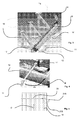
Figure 1 shows schematically one example of one embodiment of a device according to the invention. -
Figure 2 shows schematically an enlarged partial image offigure 1 . -
Figure 3 shows schematically one example arrangement for mounting an example of one embodiment of a device according to the invention. -
Figure 4 shows schematically an example for changing a nozzle of a device according to an embodiment of the invention. -
Figure 5 shows schematically some possibilities for cutting paths of one embodiment of the invention. -
Figure 6 shows schematically one example of one embodiment of a device according to the invention. -
Figure 7 shows schematically some possibilities for cutting paths of one embodiment of the invention. -
Figure 8 shows schematically some possibilities for cutting paths of one embodiment of the invention. - In the following description same reference signs designate for similar components unless otherwise mentioned and it should be understood that the examples are susceptible of modification in order to adapt to different usages and conditions within the frames of the invention.
- In the example of
figures 1 - 2 the turn-up device for a reel-up of a fiber web machine comprises alinear module 15 withmotor 14. Onewater jet nozzle 11 is attached to cuttingarm 12. Other end of the cuttingarm 12 is movably attached to the slide surface of thelinear module 15 and has a turning joint 17. In thisexample stoppers 13 attached at each end of the linear module spaced from the end limit the main cutting movement and give the mechanical impulse for the edge area movement and turning of the cuttingarm 12 with thenozzle 11 around the turning joint 17. - As shown in the example of
figure 3 device 10 is attached to frame of a reel-up byframe parts 18 that support thedevice 10 and are attached to thelinear module 15. Web W to be cut is located below thedevice 10 and the cutting movement of the cuttingarm 12 with thenozzle 11 is arrange to cover the whole width of the web by combination of the main cutting movement and the edge cutting movement / movements. - The
device 10 in the embodiment of one nozzle comprises onenozzle 11 and the edge cutting 21 A, 21 B is done by turning the cuttingarm 12 to accomplish a cutting movement deviating from the substantially linearmain cutting movement 20. Thedevice 20 comprises according to a preferred feature a turning joint 17 and mechanical lever mechanism i.e.stopper 13 by which when the cuttingarm 12 reaches atstopper 13 the unlocking for the turning joint 17 is provided by a lever mechanism (not shown) providing for the turning of the cuttingarm 12. - In
figure 4 is shown one example for the nozzle change and maintenance position of the cuttingarm 12. In the figure thenozzle 11 and the cuttingarm 12 are in a cutting position but the cuttingarm 12 with thenozzle 11 is turnable around the turning joint 17 to the change and maintenance position on the side of the device as shown by movement path M. In the embodiment of two nozzles advantageously each nozzle is turned at different sides of the reel up. - As shown in
figure 5 the cutting path of the water jet for cutting the web comprises themain cutting path 20 formed by the main cutting movement of the cuttingarm 12 and thenozzle 11 in the embodiment of the invention in which one nozzle is used. Themain cutting path 20 covers at least 60 %, advantageously at least 75 % of the width of the web. Theedge cutting path 21 A; 21 B are formed by turning the cuttingarm 12 with thenozzle 11 around the turning joint. Several different forms for theedge cutting path 21 A; 21 B are possible, depending on the speed of the web, the speed of the turning movement, the set up values for turning etc. - In
figure 6 is a very schematic presentation of one embodiment of the invention in which twonozzles 11 A; 11 B are used instead of one nozzle11 and each nozzle has itsown cutting arm linear module 15 is needed. In this embodiment the main cutting path is done by one nozzle and the edge cutting path is done by the other nozzle for example as shown in examples offigures 7 and 8 . - In
figures 7 and 8 are schematic examples of the cutting movements. In example offigure 7 the web is cut by using the bothnozzles figure 8 eachnozzle 11 A; 11 B ha sit own control valve and thus one of the cuts can be limited to the edge area only. - As shown in the previous figures the water jet turn up
device 10 comprises onecutting module 15, advantageously a linear module and at least onenozzle 11; 11 A, 11 B. In the method the cutting path comprises amain cutting movement 20 and an edgearea cutting movement 21 A; 21 B. In the method over 50% advantageously at least 60 % and more advantageously over 75 % of the cutting path is cut by onenozzle 11; 11A;11 B and the edge area cutting is advantageously in the end of the cutting path. According to further advantageous features thedevice 10 has one full widthlinear module 15 that provides for full width cutting of the web W from one edge to the other edge. One 11 or two 11 A, 11 B nozzles are attached by cuttingarm 12 /cuttingarms - In the embodiment of two cutting nozzles the device is advantageously provided with control system for controlling the cutting of each nozzle and for arranging a delay in cutting with the second nozzle for achieving crossing cutting paths in order to minimize the amount of broke, as shown in
figure 8 . - Above some preferred embodiments and examples of the invention have been described but many modifications are possible to those presented.
Claims (12)
- Method in turn-up of reeling of fiber webs, in which method the web is reeled by a reeling drum of a reel-up onto a parent roll, by which when the parent roll has reached the desired diameter size, reeling is changed from the parent roll of desired size onto a new parent roll, in which method, the web is cut by jet cutting means and beginning part of the cut web is directed onto a reeling shaft a new parent roll, characterized in that in the method the cutting path of the jet cutting means comprises a main cutting path and at least one edge area cutting path and that length of the main cutting path comprises at least 60 % of the whole cutting path length from one edge of the web (W) to the other edge of the web (W).
- Method according to claim 1, characterized in that in the method at least 75 % of the cutting path is covered by the main cutting path.
- Method according to claim 1, characterized in that the edge area cutting is advantageously in the end of the cutting path.
- Method according to claim 1, characterized in that in the method the web (W) is cut by a water jet device with one nozzle (11) and the edge cutting is provided by turning a cutting arm (12) of the nozzle (11) around pivot point (17) to accomplish a cutting path (21 A; 21 B) deviating from the essentially linear main cutting path (20).
- Method according to claim 1, characterized in that in the method the main cutting path is cut by one water jet from one nozzle (11 A) and the edge cutting path is cut by another water jet from another nozzle (11B).
- Turn-up device for a reel-up of fiber webs, characterized in that the device (10) comprises one cutting module (15) and at least one nozzle (11) for jet cutting, which is attached movably and turnably to the module (15) by a cutting arm (12).
- Device according to claim 6, characterized in that the device further comprises a pivot point (17) and mechanical lever mechanism (13) by which the nozzle (11) is unlocked for the turning of the cutting arm around the pivot point (17).
- Device according to claim 6, characterized in that in the device (10) the cutting module is a linear module (15).
- Device according to claim 6, characterized in that two nozzles (11 A, 11 B) are attached by cutting arms (12A, 12B) to a slide attached transferrable to the module (15).
- Device according to claim 9 characterized in that the cutting arms (12A, 12B) are consisted of a T-shaped arm construction such that only one channel from cutting jet source is needed.
- Device according to claim 9 characterized in that the cutting arms (12A, 12B) are of different length such that in cutting situation the nozzle the first is closer to the module than the one coming behind thus making the web slice (WB) in between the cuts narrowing.
- Device according to claim 6 characterized in that the nozzles (11; 11 A, 11 B) the device (10) is provided with control system for controlling the cutting of each nozzle.
Priority Applications (4)
| Application Number | Priority Date | Filing Date | Title |
|---|---|---|---|
| EP20110160819 EP2505535A1 (en) | 2011-04-01 | 2011-04-01 | Method in turn-up of reeling of fiber webs and a turn-up device for a reel-up of fiber webs |
| CA2769845A CA2769845C (en) | 2011-04-01 | 2012-02-29 | Method in turn-up of reeling of fiber webs and a turn-up device for a reel-up of fiber webs |
| US13/434,609 US8833218B2 (en) | 2011-04-01 | 2012-03-29 | Method in turn-up of reeling of fiber webs and a turn-up device for a reel-up of fiber webs |
| CN201210101760.2A CN102730458B (en) | 2011-04-01 | 2012-04-01 | A method in turn-up of reeling of fiber webs and a turn-up device for a reel-up of fiber webs |
Applications Claiming Priority (1)
| Application Number | Priority Date | Filing Date | Title |
|---|---|---|---|
| EP20110160819 EP2505535A1 (en) | 2011-04-01 | 2011-04-01 | Method in turn-up of reeling of fiber webs and a turn-up device for a reel-up of fiber webs |
Publications (1)
| Publication Number | Publication Date |
|---|---|
| EP2505535A1 true EP2505535A1 (en) | 2012-10-03 |
Family
ID=44358287
Family Applications (1)
| Application Number | Title | Priority Date | Filing Date |
|---|---|---|---|
| EP20110160819 Withdrawn EP2505535A1 (en) | 2011-04-01 | 2011-04-01 | Method in turn-up of reeling of fiber webs and a turn-up device for a reel-up of fiber webs |
Country Status (4)
| Country | Link |
|---|---|
| US (1) | US8833218B2 (en) |
| EP (1) | EP2505535A1 (en) |
| CN (1) | CN102730458B (en) |
| CA (1) | CA2769845C (en) |
Cited By (1)
| Publication number | Priority date | Publication date | Assignee | Title |
|---|---|---|---|---|
| US8833218B2 (en) | 2011-04-01 | 2014-09-16 | Valmet Technologies, Inc. | Method in turn-up of reeling of fiber webs and a turn-up device for a reel-up of fiber webs |
Families Citing this family (2)
| Publication number | Priority date | Publication date | Assignee | Title |
|---|---|---|---|---|
| EP3521220B1 (en) * | 2018-02-06 | 2020-06-03 | Valmet Technologies Oy | A turn-up method and a turn-up device for a reel-up for reeling of fiber webs |
| CN118423706B (en) * | 2024-04-30 | 2024-11-01 | 大唐吉林发电有限公司长春第三热电分公司 | Coal-fired loading attachment for boiler of thermal power plant |
Citations (9)
| Publication number | Priority date | Publication date | Assignee | Title |
|---|---|---|---|---|
| US4695004A (en) * | 1985-04-30 | 1987-09-22 | J. M. Voith Gmbh | Method for transferring a web from a finished roll to a new core, and drum winder for the application of the method |
| US5360179A (en) | 1991-11-18 | 1994-11-01 | Valmet Paper Machinery Inc. | Method and device for reeling a web |
| EP1035053A2 (en) * | 1999-03-10 | 2000-09-13 | Voith Sulzer Papiertechnik Patent GmbH | Method for winding a material web and winding machine to perform the method |
| EP1035056A2 (en) * | 1999-03-10 | 2000-09-13 | Voith Sulzer Papiertechnik Patent GmbH | Method for winding a material web and winding machine to perform the method |
| US6135000A (en) | 1999-01-25 | 2000-10-24 | Paprima Industries Inc. | Web cutting apparatus for use in a papermaking machine |
| DE10338781A1 (en) * | 2003-08-23 | 2005-03-17 | Voith Paper Patent Gmbh | Method for transferring material web running over winding rollers involves separating web along single continuous separation line and using air stream to transfer and guide it to winding core |
| WO2008125723A1 (en) * | 2007-04-12 | 2008-10-23 | Metso Paper, Inc. | Reeling apparatus for fiber web and method of reeling fiber web |
| DE102008009958B3 (en) * | 2008-02-20 | 2009-05-14 | Paprima Industries Inc., Dorval | Method for protecting web end of paper wed, involves changing of one reel to another reel, where web end runs between paper roller and latter reel |
| FI120445B (en) | 2006-12-05 | 2009-10-30 | Metso Paper Inc | Water change device in a wheelchair in a fiber web machine |
Family Cites Families (6)
| Publication number | Priority date | Publication date | Assignee | Title |
|---|---|---|---|---|
| US3365992A (en) * | 1965-09-23 | 1968-01-30 | Donald F. Dreher | Web severing apparatus |
| DE2656242C2 (en) * | 1976-12-11 | 1978-12-21 | J.M. Voith Gmbh, 7920 Heidenheim | Device for cutting a fiber web |
| US4444362A (en) * | 1982-03-05 | 1984-04-24 | Beloit Corporation | Apparatus and method for starting successive leading ends on travelling web in a winder |
| US4445646A (en) * | 1982-03-05 | 1984-05-01 | Beloit Corporation | Apparatus and method for starting successive leading ends on travelling web in a winder |
| US5762759A (en) * | 1997-01-27 | 1998-06-09 | Beloit Technologies, Inc. | Tail threading system for a papermaking machine |
| EP2505535A1 (en) | 2011-04-01 | 2012-10-03 | Metso Paper Inc. | Method in turn-up of reeling of fiber webs and a turn-up device for a reel-up of fiber webs |
-
2011
- 2011-04-01 EP EP20110160819 patent/EP2505535A1/en not_active Withdrawn
-
2012
- 2012-02-29 CA CA2769845A patent/CA2769845C/en not_active Expired - Fee Related
- 2012-03-29 US US13/434,609 patent/US8833218B2/en not_active Expired - Fee Related
- 2012-04-01 CN CN201210101760.2A patent/CN102730458B/en not_active Expired - Fee Related
Patent Citations (9)
| Publication number | Priority date | Publication date | Assignee | Title |
|---|---|---|---|---|
| US4695004A (en) * | 1985-04-30 | 1987-09-22 | J. M. Voith Gmbh | Method for transferring a web from a finished roll to a new core, and drum winder for the application of the method |
| US5360179A (en) | 1991-11-18 | 1994-11-01 | Valmet Paper Machinery Inc. | Method and device for reeling a web |
| US6135000A (en) | 1999-01-25 | 2000-10-24 | Paprima Industries Inc. | Web cutting apparatus for use in a papermaking machine |
| EP1035053A2 (en) * | 1999-03-10 | 2000-09-13 | Voith Sulzer Papiertechnik Patent GmbH | Method for winding a material web and winding machine to perform the method |
| EP1035056A2 (en) * | 1999-03-10 | 2000-09-13 | Voith Sulzer Papiertechnik Patent GmbH | Method for winding a material web and winding machine to perform the method |
| DE10338781A1 (en) * | 2003-08-23 | 2005-03-17 | Voith Paper Patent Gmbh | Method for transferring material web running over winding rollers involves separating web along single continuous separation line and using air stream to transfer and guide it to winding core |
| FI120445B (en) | 2006-12-05 | 2009-10-30 | Metso Paper Inc | Water change device in a wheelchair in a fiber web machine |
| WO2008125723A1 (en) * | 2007-04-12 | 2008-10-23 | Metso Paper, Inc. | Reeling apparatus for fiber web and method of reeling fiber web |
| DE102008009958B3 (en) * | 2008-02-20 | 2009-05-14 | Paprima Industries Inc., Dorval | Method for protecting web end of paper wed, involves changing of one reel to another reel, where web end runs between paper roller and latter reel |
Cited By (1)
| Publication number | Priority date | Publication date | Assignee | Title |
|---|---|---|---|---|
| US8833218B2 (en) | 2011-04-01 | 2014-09-16 | Valmet Technologies, Inc. | Method in turn-up of reeling of fiber webs and a turn-up device for a reel-up of fiber webs |
Also Published As
| Publication number | Publication date |
|---|---|
| CN102730458A (en) | 2012-10-17 |
| CA2769845C (en) | 2016-09-27 |
| CA2769845A1 (en) | 2012-10-01 |
| CN102730458B (en) | 2015-07-15 |
| US8833218B2 (en) | 2014-09-16 |
| US20130075520A1 (en) | 2013-03-28 |
Similar Documents
| Publication | Publication Date | Title |
|---|---|---|
| US5360179A (en) | Method and device for reeling a web | |
| US5782426A (en) | Method and device for reeling a paper or board web | |
| US9511968B2 (en) | Reel-up and a method for winding into a roll a paper web and for starting a new roll | |
| EP1051343B1 (en) | Reel-up and method for changing a roll | |
| EP2703326B1 (en) | Method for separating partial webs in a slitter winder | |
| CA2769845C (en) | Method in turn-up of reeling of fiber webs and a turn-up device for a reel-up of fiber webs | |
| EP2132119B1 (en) | Reeling apparatus for fiber web and method of reeling fiber web | |
| JP2021524832A (en) | A device for cutting material webs into individual sheets in web storage | |
| EP3452394B1 (en) | An apparatus for winding a web of paper material and a method of removing dust | |
| US8807066B2 (en) | Device for applying adhesive in a slitter-winder of fiber web machine | |
| EP2532613B1 (en) | Method in reeling of fiber webs and a reel-up | |
| US11834287B1 (en) | Methods and apparatus for improved web threading accomodation by a paperband turn-up system | |
| US20200407185A1 (en) | Turn-up Device For a Reel-up Forming a Single Reject Part | |
| FI131296B1 (en) | Clamping roller with cleaning device | |
| EP2540649B1 (en) | Method and arrangement in connection with an unwinder | |
| CA2703473A1 (en) | Slitter for a running fibrous web |
Legal Events
| Date | Code | Title | Description |
|---|---|---|---|
| PUAI | Public reference made under article 153(3) epc to a published international application that has entered the european phase |
Free format text: ORIGINAL CODE: 0009012 |
|
| AK | Designated contracting states |
Kind code of ref document: A1 Designated state(s): AL AT BE BG CH CY CZ DE DK EE ES FI FR GB GR HR HU IE IS IT LI LT LU LV MC MK MT NL NO PL PT RO RS SE SI SK SM TR |
|
| AX | Request for extension of the european patent |
Extension state: BA ME |
|
| 17P | Request for examination filed |
Effective date: 20121228 |
|
| RAP1 | Party data changed (applicant data changed or rights of an application transferred) |
Owner name: VALMET TECHNOLOGIES, INC. |
|
| GRAP | Despatch of communication of intention to grant a patent |
Free format text: ORIGINAL CODE: EPIDOSNIGR1 |
|
| RIC1 | Information provided on ipc code assigned before grant |
Ipc: B65H 19/26 20060101AFI20170112BHEP Ipc: B65H 19/28 20060101ALI20170112BHEP |
|
| INTG | Intention to grant announced |
Effective date: 20170214 |
|
| STAA | Information on the status of an ep patent application or granted ep patent |
Free format text: STATUS: THE APPLICATION IS DEEMED TO BE WITHDRAWN |
|
| 18D | Application deemed to be withdrawn |
Effective date: 20170627 |