EP2505501A1 - Method of manufacturing a fibrereinforced profile - Google Patents
Method of manufacturing a fibrereinforced profile Download PDFInfo
- Publication number
- EP2505501A1 EP2505501A1 EP11400026A EP11400026A EP2505501A1 EP 2505501 A1 EP2505501 A1 EP 2505501A1 EP 11400026 A EP11400026 A EP 11400026A EP 11400026 A EP11400026 A EP 11400026A EP 2505501 A1 EP2505501 A1 EP 2505501A1
- Authority
- EP
- European Patent Office
- Prior art keywords
- drift
- fibre
- sets
- laminate
- periphery
- Prior art date
- Legal status (The legal status is an assumption and is not a legal conclusion. Google has not performed a legal analysis and makes no representation as to the accuracy of the status listed.)
- Granted
Links
- 238000004519 manufacturing process Methods 0.000 title claims abstract description 16
- 238000000034 method Methods 0.000 claims abstract description 16
- 239000000463 material Substances 0.000 claims description 9
- 239000011888 foil Substances 0.000 claims description 5
- 238000003825 pressing Methods 0.000 claims 1
- 238000010792 warming Methods 0.000 claims 1
- OKTJSMMVPCPJKN-UHFFFAOYSA-N Carbon Chemical compound [C] OKTJSMMVPCPJKN-UHFFFAOYSA-N 0.000 description 3
- 229910052799 carbon Inorganic materials 0.000 description 3
- 230000000694 effects Effects 0.000 description 2
- 239000003822 epoxy resin Substances 0.000 description 2
- 239000000835 fiber Substances 0.000 description 2
- 229920000647 polyepoxide Polymers 0.000 description 2
- 229920002994 synthetic fiber Polymers 0.000 description 2
- XUIMIQQOPSSXEZ-UHFFFAOYSA-N Silicon Chemical compound [Si] XUIMIQQOPSSXEZ-UHFFFAOYSA-N 0.000 description 1
- 238000005452 bending Methods 0.000 description 1
- 230000005540 biological transmission Effects 0.000 description 1
- 239000002131 composite material Substances 0.000 description 1
- 239000011152 fibreglass Substances 0.000 description 1
- 229910052710 silicon Inorganic materials 0.000 description 1
- 239000010703 silicon Substances 0.000 description 1
- 230000003068 static effect Effects 0.000 description 1
Images
Classifications
-
- B—PERFORMING OPERATIONS; TRANSPORTING
- B29—WORKING OF PLASTICS; WORKING OF SUBSTANCES IN A PLASTIC STATE IN GENERAL
- B29C—SHAPING OR JOINING OF PLASTICS; SHAPING OF MATERIAL IN A PLASTIC STATE, NOT OTHERWISE PROVIDED FOR; AFTER-TREATMENT OF THE SHAPED PRODUCTS, e.g. REPAIRING
- B29C70/00—Shaping composites, i.e. plastics material comprising reinforcements, fillers or preformed parts, e.g. inserts
- B29C70/04—Shaping composites, i.e. plastics material comprising reinforcements, fillers or preformed parts, e.g. inserts comprising reinforcements only, e.g. self-reinforcing plastics
- B29C70/28—Shaping operations therefor
- B29C70/40—Shaping or impregnating by compression not applied
- B29C70/42—Shaping or impregnating by compression not applied for producing articles of definite length, i.e. discrete articles
- B29C70/44—Shaping or impregnating by compression not applied for producing articles of definite length, i.e. discrete articles using isostatic pressure, e.g. pressure difference-moulding, vacuum bag-moulding, autoclave-moulding or expanding rubber-moulding
- B29C70/446—Moulding structures having an axis of symmetry or at least one channel, e.g. tubular structures, frames
-
- B—PERFORMING OPERATIONS; TRANSPORTING
- B64—AIRCRAFT; AVIATION; COSMONAUTICS
- B64C—AEROPLANES; HELICOPTERS
- B64C27/00—Rotorcraft; Rotors peculiar thereto
- B64C27/54—Mechanisms for controlling blade adjustment or movement relative to rotor head, e.g. lag-lead movement
- B64C27/72—Means acting on blades
- B64C2027/7205—Means acting on blades on each blade individually, e.g. individual blade control [IBC]
- B64C2027/7261—Means acting on blades on each blade individually, e.g. individual blade control [IBC] with flaps
- B64C2027/7266—Means acting on blades on each blade individually, e.g. individual blade control [IBC] with flaps actuated by actuators
- B64C2027/7283—Means acting on blades on each blade individually, e.g. individual blade control [IBC] with flaps actuated by actuators of the piezoelectric type
-
- Y—GENERAL TAGGING OF NEW TECHNOLOGICAL DEVELOPMENTS; GENERAL TAGGING OF CROSS-SECTIONAL TECHNOLOGIES SPANNING OVER SEVERAL SECTIONS OF THE IPC; TECHNICAL SUBJECTS COVERED BY FORMER USPC CROSS-REFERENCE ART COLLECTIONS [XRACs] AND DIGESTS
- Y02—TECHNOLOGIES OR APPLICATIONS FOR MITIGATION OR ADAPTATION AGAINST CLIMATE CHANGE
- Y02T—CLIMATE CHANGE MITIGATION TECHNOLOGIES RELATED TO TRANSPORTATION
- Y02T50/00—Aeronautics or air transport
- Y02T50/30—Wing lift efficiency
Definitions
- the invention concerns a method for manufacturing fibre-reinforced profiles and the invention concerns in particular an actuator for a helicopter's rotor blade manufactured according to said method.
- the rotor blades of many helicopters have a GRP loop connection. Through the high load due to centrifugal forces, impact and edgewise moments, a very high static and dynamic strength is required for this application to achieve a high expected life duration.
- the loop For curing of a continuous loop under external pressure the loop is wound on the drift.
- the fibre-reinforced synthetic material positions itself.
- the external fibres are compressed through the reduction of the circumference. Due to the missing elongation they are not fully stretched and therefore they are not able to carry loads as if they would be stretched. This effect is stronger with relatively thick loops than with relatively thin loops.
- a thick loop is defined by R a /R i >1,5
- the document W02009087115 discloses a method for the production of fibre-reinforced composites with complex cross-sectional shape. The method is based on the use of centrifugal force to provide the internal pressure.
- the object of the invention is to provide a manufacturing method allowing high stiffness of all fibres in a loop and to provide an actuator for a helicopter's rotor blade manufactured according to said method.
- the invention solves the problem according to a method of manufacturing a fibre-reinforced profile with the features of claim 1 and according to an actuator manufactured by said method with the features of claim 7.
- a method of manufacturing a fibre-reinforced profile is provided with the following steps: First a drift and an external mould form is provided.
- each of said at least two sets comprising at least one laminate package of said fibre-reinforced material.
- Said laminate package is preferably composed of prepreg layers with intermediate separating foils and each of said laminate packages is longer than a fraction of the periphery of the drift and any in between laminate package of said fibre-reinforced material.
- the fraction of the periphery of the drift is defined by a division of the number of sets through the entire length of the periphery of said drift.
- said at least two sets are arranged around said drift by placing a laminate package of one of said at least two sets on the drift and placing a laminate package of another one of said at least two sets on the drift such that the preceding laminate package of the other one of said at least two sets is overlapped at least partly to form a prefabricated loop.
- said prefabricated loop is positioned inside said external mould form, said internal periphery of the external mould form being longer than the external periphery of the prefabricated loop. Pressure is applied to the internal periphery of the prefabricated loop to press said external periphery of the prefabricated loop against said internal periphery of the external mould to cure the prefabricated loop to the fibre-reinforced profile.
- the inventive method of manufacturing it is ensured that for curing all fibres are uniformly stretched and hence the laminate quality and the mechanical characteristics of the loop reach their respective optima.
- the inventive method is in particular advantageous if applied to rotor blades for best quality, stiffness and stability of the resulting fibre-reinforced profile.
- a further advantage of the invention is a less complex production and an increase in reproducibility of production results at overall reduced production costs.
- the fibres used for any of the laminate packages are carbon fibres with an elasticity modulus of up to 210 000 N/mm 2 .
- the intermediate separating foils between the layers allow areas in the laminate packages without shear stresses for increased flexibility at high tensile strength of the laminate packages.
- said prefabricated loop is removed from the drift before positioning said prefabricated loop inside said external mould form thus allowing less complex tools for the inventive method of manufacturing.
- the laminate packages are tapered at their ends to allow smooth overlapping of the laminate packages.
- overlapping of the tapered ends of the laminate packages is effected along two vertices of the drift where the most advantageous effects of stretching the outer laminate packages can be expected.
- the respective laminate packages of the at least two sets overlap to an extend after arrangement to the drift that complete adaption of the outer laminate packages of said prefabricated loop to the internal periphery of the external mould form occurs.
- the sets of overlapping laminate packages are warmed to cure.
- an actuator is manufactured by a method according to any of the preceding embodiments, said actuator with piezostacks integrated into the fibre-reinforced profile being suitable for actuation of rotor wing flaps.
- the high stiffness of the profiles manufactured according to the invention allows the necessary transmission ratios resulting from the small actuation distances of piezostacks.
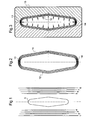
- Fig. 1 in a first step of the method of manufacturing a fibre-reinforced profile 10 several prepreg laminate packages 1-8 with from inside to outside increasing lengths are provided by putting them down on an even area.
- Each of said laminate packages 1-8 is built up from 11 unidirectional carbon fibre layers, namely prepregs, with respectively two intermediate separating foils between two adjacent layers.
- the layers are increasing in length and are arranged to form a wedge shape resulting in tapered ends for each of said laminate packages 1-8.
- the intermediate separating foils leave the ends and a mid area free between two adjacent layers allowing unhampered cure of the prepreg layers at the ends and the mid area.
- Each of said laminate packages 1-8 is longer than half of the periphery of a drift 9 and any in between laminate packages 1-3 or 5-7 of said fibre-reinforced material. Said laminate packages 1-8 are arranged to form a wedge shape with the longest laminate packages 1, 8 at the outside.
- the diameter of the drift 9 is reduced against the final contour of the fibre-reinforced profile 10.
- the length of such a contour may be about 150 mm.
- the contour is cut to a height of 23 mm by means of a clamping device.
- a right hand and a left hand semi-monocoque 11, 12 are formed from said laminate packages 1-8 to a prefabricated loop by repeatingly putting said laminate packages 1-8 on the drift 9 in a way that if one laminate package 1-4 of one set is put down on the drift 9 an overlapping laminate package 5-8 from the opposite set is put down on the drift 9 or vice versa with the overlapping of said laminate packages 1-8 occurring on both vertices 13, 14 of the drift 9 up to the lay-out of the total prefabricated loop 11, 12.
- the prefabricated loop 11, 12 is removed from the drift 9 and positioned in an external mould form 15.
- the prefabricated loop 11, 12 is a little smaller than the contour of the mould form 15.
- Curing of the prefabricated loop runs under internal pressure to the internal periphery of the prefabricated loop to urge said external periphery of the prefabricated loop against said internal contour of the external mould form 15 to form the fibre-reinforced profile 10.
- the internal pressure is in the range of 4 bar and is applied by means of a silicon pressure bag.
- Overlaps of the laminate packages 1-8 at their respective ends at the vertices 13, 14 are directed by the internal pressure until full contact is reached of the external periphery of the prefabricated loop 11, 12 to said internal contour of the external mould form 15.
- the external mould form 15 may be warmed to cure the prefabricated loop 11, 12.
Abstract
And an actuator manufactured according to said method.
Description
- The invention concerns a method for manufacturing fibre-reinforced profiles and the invention concerns in particular an actuator for a helicopter's rotor blade manufactured according to said method.
- It is known in aeronautical industry to manufacture profiles from fibre-reinforced synthetic material, such as loops made of reinforced fibre glass (GRP) or reinforced carbon fibres (CRP) bedded in epoxy resin.
- Different types of production processes are state of the art:
- prepreg straps are wound endlessly on a drift;
- prepreg straps are put with a looping angle of 180° around a drift;
- soaked fibre bundles are wound endlessly with epoxy resin on a drift.
- The rotor blades of many helicopters have a GRP loop connection. Through the high load due to centrifugal forces, impact and edgewise moments, a very high static and dynamic strength is required for this application to achieve a high expected life duration.
- For curing of a continuous loop under external pressure the loop is wound on the drift. During curing under external pressure, i. e. vacuum and if necessary autoclave pressure, the fibre-reinforced synthetic material positions itself. In particular the external fibres are compressed through the reduction of the circumference. Due to the missing elongation they are not fully stretched and therefore they are not able to carry loads as if they would be stretched. This effect is stronger with relatively thick loops than with relatively thin loops. A thick loop is defined by Ra/Ri >1,5 and a thin loop is defined by Ra/Ri = 1-1,5 with Ra being the outer radius of the loop and Ri being the inner radius of the loop.
- To remedy said disadvantage curing of a continuous loop under internal pressure in an external form might be considered. However, only the internal fibres are stretched while applying the internal pressure, such as vacuum and if necessary autoclave pressure, pressure bag. The internal pressure cannot be transferred up to the external form. The consequence is that only the internal fibres of such a continuous loop are sufficiently stretched and carry the loads.
- The document
US2009115089 discloses a method for curing using internal pressure. - The document
W02009087115 discloses a method for the production of fibre-reinforced composites with complex cross-sectional shape. The method is based on the use of centrifugal force to provide the internal pressure. - The object of the invention is to provide a manufacturing method allowing high stiffness of all fibres in a loop and to provide an actuator for a helicopter's rotor blade manufactured according to said method.
- The invention solves the problem according to a method of manufacturing a fibre-reinforced profile with the features of claim 1 and according to an actuator manufactured by said method with the features of claim 7.
- According to the invention a method of manufacturing a fibre-reinforced profile is provided with the following steps: First a drift and an external mould form is provided.
- Subsequently at least two sets of fibre-reinforced material are provided with each of said at least two sets comprising at least one laminate package of said fibre-reinforced material. Said laminate package is preferably composed of prepreg layers with intermediate separating foils and each of said laminate packages is longer than a fraction of the periphery of the drift and any in between laminate package of said fibre-reinforced material. The fraction of the periphery of the drift is defined by a division of the number of sets through the entire length of the periphery of said drift. Subsequently said at least two sets are arranged around said drift by placing a laminate package of one of said at least two sets on the drift and placing a laminate package of another one of said at least two sets on the drift such that the preceding laminate package of the other one of said at least two sets is overlapped at least partly to form a prefabricated loop. Subsequently said prefabricated loop is positioned inside said external mould form, said internal periphery of the external mould form being longer than the external periphery of the prefabricated loop. Pressure is applied to the internal periphery of the prefabricated loop to press said external periphery of the prefabricated loop against said internal periphery of the external mould to cure the prefabricated loop to the fibre-reinforced profile. E. g.: The fraction of the periphery of the drift resulting from the division of the number of two sets through the entire length of the periphery of said drift is half, three sets would make the fraction = 1/3, and so on. With the inventive method of manufacturing it is ensured that for curing all fibres are uniformly stretched and hence the laminate quality and the mechanical characteristics of the loop reach their respective optima. The inventive method is in particular advantageous if applied to rotor blades for best quality, stiffness and stability of the resulting fibre-reinforced profile. A further advantage of the invention is a less complex production and an increase in reproducibility of production results at overall reduced production costs. The fibres used for any of the laminate packages are carbon fibres with an elasticity modulus of up to 210 000 N/mm2. The intermediate separating foils between the layers allow areas in the laminate packages without shear stresses for increased flexibility at high tensile strength of the laminate packages.
- According to a preferred embodiment of the invention said prefabricated loop is removed from the drift before positioning said prefabricated loop inside said external mould form thus allowing less complex tools for the inventive method of manufacturing.
- According to a further preferred embodiment of the invention the laminate packages are tapered at their ends to allow smooth overlapping of the laminate packages.
- According to a further preferred embodiment of the invention overlapping of the tapered ends of the laminate packages is effected along two vertices of the drift where the most advantageous effects of stretching the outer laminate packages can be expected.
- According to a further preferred embodiment of the invention the respective laminate packages of the at least two sets overlap to an extend after arrangement to the drift that complete adaption of the outer laminate packages of said prefabricated loop to the internal periphery of the external mould form occurs.
- According to a further preferred embodiment of the invention the sets of overlapping laminate packages are warmed to cure.
- According to the invention an actuator is manufactured by a method according to any of the preceding embodiments, said actuator with piezostacks integrated into the fibre-reinforced profile being suitable for actuation of rotor wing flaps. The high stiffness of the profiles manufactured according to the invention allows the necessary transmission ratios resulting from the small actuation distances of piezostacks.
- A preferred embodiment of the invention is presented by way of the following description with reference to the attached drawings.
-
Fig. 1 shows two sets of laminate packages of fibre-reinforced material arranged along a drift according to the invention, -
Fig. 2 shows curing of a half shell bending loop according to the invention, and -
Fig. 3 shows a prefabricated loop inside an external mould form according to the invention. - According to
Fig. 1 in a first step of the method of manufacturing a fibre-reinforced profile 10 several prepreg laminate packages 1-8 with from inside to outside increasing lengths are provided by putting them down on an even area. Each of said laminate packages 1-8 is built up from 11 unidirectional carbon fibre layers, namely prepregs, with respectively two intermediate separating foils between two adjacent layers. The layers are increasing in length and are arranged to form a wedge shape resulting in tapered ends for each of said laminate packages 1-8. The intermediate separating foils leave the ends and a mid area free between two adjacent layers allowing unhampered cure of the prepreg layers at the ends and the mid area. - Each of said laminate packages 1-8 is longer than half of the periphery of a
drift 9 and any in between laminate packages 1-3 or 5-7 of said fibre-reinforced material. Said laminate packages 1-8 are arranged to form a wedge shape with the longest laminate packages 1, 8 at the outside. - The diameter of the
drift 9 is reduced against the final contour of the fibre-reinforced profile 10. The length of such a contour may be about 150 mm. The contour is cut to a height of 23 mm by means of a clamping device. - According to
Fig. 2 a right hand and aleft hand semi-monocoque 11, 12 are formed from said laminate packages 1-8 to a prefabricated loop by repeatingly putting said laminate packages 1-8 on thedrift 9 in a way that if one laminate package 1-4 of one set is put down on thedrift 9 an overlapping laminate package 5-8 from the opposite set is put down on thedrift 9 or vice versa with the overlapping of said laminate packages 1-8 occurring on bothvertices drift 9 up to the lay-out of the totalprefabricated loop 11, 12. - According to
Fig. 3 theprefabricated loop 11, 12 is removed from thedrift 9 and positioned in anexternal mould form 15. In the not cured condition theprefabricated loop 11, 12 is a little smaller than the contour of themould form 15. Curing of the prefabricated loop runs under internal pressure to the internal periphery of the prefabricated loop to urge said external periphery of the prefabricated loop against said internal contour of theexternal mould form 15 to form the fibre-reinforced profile 10. The internal pressure is in the range of 4 bar and is applied by means of a silicon pressure bag. Overlaps of the laminate packages 1-8 at their respective ends at thevertices prefabricated loop 11, 12 to said internal contour of theexternal mould form 15. - The
external mould form 15 may be warmed to cure theprefabricated loop 11, 12.
Claims (7)
- A method of manufacturing a fibre-reinforced profile (10) with the following steps:providing a drift (9) and an external mould form (15),providing at least two sets of fibre-reinforced material with each of said at least two sets comprising at least one laminate package (1-8) of said fibre-reinforced material, preferably comprising prepreg layers (1-8) of said fibre-reinforced material with intermediate separating foils, each of said laminate packages (1-8) being longer than a fraction of the periphery of the drift (9) and any in between laminate package (1-3, 5-7) of said fibre-reinforced material, the fraction of the periphery of the drift (9) being defined by a division of the number of sets through the entire length of the periphery of said drift (9),arranging said at least two sets around said drift (9) by placing a laminate package (1-4) of one of said at least two sets on the drift (9) and placing a laminate package (5-8) of another one of said at least two sets on the drift such that the preceding laminate package of the other one of said at least two sets is overlapped at least partly to form a prefabricated loop (11, 12),positioning said prefabricated loop (11, 12) inside said external mould form (15), said internal contour of the external mould form (15) being longer than the external periphery of the prefabricated loop (11, 12), andapplying pressure to the internal periphery of the prefabricated loop (11, 12) to press said external periphery of the prefabricated loop (11, 12) against said internal contour of the external mould form (15) to cure the prefabricated loop (11, 12) to the fibre-reinforced profile (10).
- The method according to claim 1,
characterized by removing said prefabricated loop (11, 12) from the drift (9) before positioning said prefabricated loop (11, 12) inside said external mould form (15). - The method according to claim 1,
characterized by tapering the laminate packages (1-8) at their ends. - The method according to claim 3,
characterized by overlapping the tapered ends of the laminate packages (1-8) on two vertices of the drift. - The method according to claim 1,
characterized by overlapping the laminate packages to an extend that a complete adaption to the internal contour of the external mould form (15) is effected. - The method according to claim 1,
characterized by warming the sets of overlapping laminate packages (1-8) to cure. - An actuator manufactured by a method according to any of the preceding claims for actuation of rotor wing flaps with piezostacks integrated into the fibre-reinforced profile (10).
Priority Applications (1)
| Application Number | Priority Date | Filing Date | Title |
|---|---|---|---|
| EP11400026.8A EP2505501B1 (en) | 2011-03-30 | 2011-03-30 | Method of manufacturing a fibre-reinforced profile |
Applications Claiming Priority (1)
| Application Number | Priority Date | Filing Date | Title |
|---|---|---|---|
| EP11400026.8A EP2505501B1 (en) | 2011-03-30 | 2011-03-30 | Method of manufacturing a fibre-reinforced profile |
Publications (2)
| Publication Number | Publication Date |
|---|---|
| EP2505501A1 true EP2505501A1 (en) | 2012-10-03 |
| EP2505501B1 EP2505501B1 (en) | 2014-10-29 |
Family
ID=44652063
Family Applications (1)
| Application Number | Title | Priority Date | Filing Date |
|---|---|---|---|
| EP11400026.8A Not-in-force EP2505501B1 (en) | 2011-03-30 | 2011-03-30 | Method of manufacturing a fibre-reinforced profile |
Country Status (1)
| Country | Link |
|---|---|
| EP (1) | EP2505501B1 (en) |
Citations (5)
| Publication number | Priority date | Publication date | Assignee | Title |
|---|---|---|---|---|
| US4923541A (en) * | 1988-10-22 | 1990-05-08 | George Burger | Method for making composite reinforced tubes |
| US20020102373A1 (en) * | 2001-01-26 | 2002-08-01 | Demeyer Willy | Novel textile reinforced thermoplastic or thermoset pipes |
| US20050257956A1 (en) * | 2004-05-19 | 2005-11-24 | The Boeing Company | Structurally integrated circuit and associated method |
| US20090115089A1 (en) | 2007-10-31 | 2009-05-07 | Hiroyuki Oyama | Method for producing resin structure |
| WO2009087115A1 (en) | 2008-01-11 | 2009-07-16 | Airbus Deutschland Gmbh | Process for producing (part-)annular, fiber reinforced, polymer containing moldings from semifinished fiber composite material products |
-
2011
- 2011-03-30 EP EP11400026.8A patent/EP2505501B1/en not_active Not-in-force
Patent Citations (5)
| Publication number | Priority date | Publication date | Assignee | Title |
|---|---|---|---|---|
| US4923541A (en) * | 1988-10-22 | 1990-05-08 | George Burger | Method for making composite reinforced tubes |
| US20020102373A1 (en) * | 2001-01-26 | 2002-08-01 | Demeyer Willy | Novel textile reinforced thermoplastic or thermoset pipes |
| US20050257956A1 (en) * | 2004-05-19 | 2005-11-24 | The Boeing Company | Structurally integrated circuit and associated method |
| US20090115089A1 (en) | 2007-10-31 | 2009-05-07 | Hiroyuki Oyama | Method for producing resin structure |
| WO2009087115A1 (en) | 2008-01-11 | 2009-07-16 | Airbus Deutschland Gmbh | Process for producing (part-)annular, fiber reinforced, polymer containing moldings from semifinished fiber composite material products |
Non-Patent Citations (1)
| Title |
|---|
| TAEOH LEE ET AL: "Design of piezostack-driven trailing-edge flap actuator for helicopter rotors; Piezostack-driven trailing-edge flap actuator", SMART MATERIALS AND STRUCTURES, IOP PUBLISHING LTD., BRISTOL, GB, vol. 10, no. 1, 1 February 2001 (2001-02-01), pages 15 - 24, XP020071442, ISSN: 0964-1726, DOI: 10.1088/0964-1726/10/1/302 * |
Also Published As
| Publication number | Publication date |
|---|---|
| EP2505501B1 (en) | 2014-10-29 |
Similar Documents
| Publication | Publication Date | Title |
|---|---|---|
| CN106457696B (en) | Wind turbine blade component manufactured in two steps | |
| CN106457719B (en) | Wind turbine blade with improved fiber transition | |
| US11752709B2 (en) | Reinforcing structure for a wind turbine blade | |
| DK2922690T3 (en) | Wind turbine blades and methods for making them | |
| DK3019741T3 (en) | WINDMILL LIVES WITH SECTIONS THAT ARE ASSEMBLED | |
| EP2983882B1 (en) | A fibre preform for laying on a curved surface of a mould | |
| US8114329B2 (en) | Wing and blade structure using pultruded composites | |
| EP2441571B1 (en) | Proces for manufacturing a composite component | |
| EP2388477B1 (en) | Blade of a wind turbine | |
| CA2711751C (en) | Helicopter blade mandrel with roller assembly and methods to make and use it | |
| CN106321345B (en) | Spar cap for wind turbine rotor blade formed from pre-treated laminate | |
| MX2012008277A (en) | Wind turbine rotor blade components and methods of making same. | |
| RU2541574C1 (en) | Helicopter rotor and production of rotor from composites | |
| EP2918398B1 (en) | A fiber-reinforced composite, a component and a method | |
| US5091029A (en) | Method of manufacturing a unitary, multi-legged helicopter rotor flexbeam made solely of composite materials | |
| EP2905464A1 (en) | Blade root section made of prestressed concrete | |
| EP2927361B1 (en) | A fiber mat, a component for a wind turbine, an apparatus for producing the fiber mat and a method for producing the fiber mat. | |
| US10647421B2 (en) | Method of fabricating a spar for a blade, a method of fabricating a blade, and a blade | |
| KR102040595B1 (en) | Aircraft rotor blade and relative forming method | |
| EP2505501A1 (en) | Method of manufacturing a fibrereinforced profile | |
| CN113165283A (en) | Method for manufacturing a blade component for a wind turbine rotor blade | |
| RU2616465C2 (en) | Method of making blades from composite material | |
| EP2955005B1 (en) | A composite structure and a method of fabricating the same | |
| US10906267B2 (en) | Composite structure | |
| CN114269554A (en) | Method for manufacturing a wind turbine blade |
Legal Events
| Date | Code | Title | Description |
|---|---|---|---|
| PUAI | Public reference made under article 153(3) epc to a published international application that has entered the european phase |
Free format text: ORIGINAL CODE: 0009012 |
|
| AK | Designated contracting states |
Kind code of ref document: A1 Designated state(s): AL AT BE BG CH CY CZ DE DK EE ES FI FR GB GR HR HU IE IS IT LI LT LU LV MC MK MT NL NO PL PT RO RS SE SI SK SM TR |
|
| AX | Request for extension of the european patent |
Extension state: BA ME |
|
| 17P | Request for examination filed |
Effective date: 20130121 |
|
| 17Q | First examination report despatched |
Effective date: 20130312 |
|
| RAP1 | Party data changed (applicant data changed or rights of an application transferred) |
Owner name: AIRBUS HELICOPTERS DEUTSCHLAND GMBH |
|
| REG | Reference to a national code |
Ref country code: DE Ref legal event code: R079 Ref document number: 602011010916 Country of ref document: DE Free format text: PREVIOUS MAIN CLASS: B64C0027540000 Ipc: B29C0070440000 |
|
| RIC1 | Information provided on ipc code assigned before grant |
Ipc: B29C 70/44 20060101AFI20140526BHEP Ipc: B64C 27/72 20060101ALI20140526BHEP |
|
| GRAP | Despatch of communication of intention to grant a patent |
Free format text: ORIGINAL CODE: EPIDOSNIGR1 |
|
| INTG | Intention to grant announced |
Effective date: 20140818 |
|
| GRAS | Grant fee paid |
Free format text: ORIGINAL CODE: EPIDOSNIGR3 |
|
| GRAA | (expected) grant |
Free format text: ORIGINAL CODE: 0009210 |
|
| AK | Designated contracting states |
Kind code of ref document: B1 Designated state(s): AL AT BE BG CH CY CZ DE DK EE ES FI FR GB GR HR HU IE IS IT LI LT LU LV MC MK MT NL NO PL PT RO RS SE SI SK SM TR |
|
| REG | Reference to a national code |
Ref country code: GB Ref legal event code: FG4D |
|
| REG | Reference to a national code |
Ref country code: CH Ref legal event code: EP |
|
| REG | Reference to a national code |
Ref country code: AT Ref legal event code: REF Ref document number: 693351 Country of ref document: AT Kind code of ref document: T Effective date: 20141115 |
|
| REG | Reference to a national code |
Ref country code: IE Ref legal event code: FG4D |
|
| REG | Reference to a national code |
Ref country code: DE Ref legal event code: R096 Ref document number: 602011010916 Country of ref document: DE Effective date: 20141211 |
|
| REG | Reference to a national code |
Ref country code: AT Ref legal event code: MK05 Ref document number: 693351 Country of ref document: AT Kind code of ref document: T Effective date: 20141029 |
|
| REG | Reference to a national code |
Ref country code: NL Ref legal event code: VDEP Effective date: 20141029 |
|
| REG | Reference to a national code |
Ref country code: LT Ref legal event code: MG4D |
|
| PG25 | Lapsed in a contracting state [announced via postgrant information from national office to epo] |
Ref country code: NO Free format text: LAPSE BECAUSE OF FAILURE TO SUBMIT A TRANSLATION OF THE DESCRIPTION OR TO PAY THE FEE WITHIN THE PRESCRIBED TIME-LIMIT Effective date: 20150129 Ref country code: FI Free format text: LAPSE BECAUSE OF FAILURE TO SUBMIT A TRANSLATION OF THE DESCRIPTION OR TO PAY THE FEE WITHIN THE PRESCRIBED TIME-LIMIT Effective date: 20141029 Ref country code: IS Free format text: LAPSE BECAUSE OF FAILURE TO SUBMIT A TRANSLATION OF THE DESCRIPTION OR TO PAY THE FEE WITHIN THE PRESCRIBED TIME-LIMIT Effective date: 20150228 Ref country code: ES Free format text: LAPSE BECAUSE OF FAILURE TO SUBMIT A TRANSLATION OF THE DESCRIPTION OR TO PAY THE FEE WITHIN THE PRESCRIBED TIME-LIMIT Effective date: 20141029 Ref country code: LT Free format text: LAPSE BECAUSE OF FAILURE TO SUBMIT A TRANSLATION OF THE DESCRIPTION OR TO PAY THE FEE WITHIN THE PRESCRIBED TIME-LIMIT Effective date: 20141029 Ref country code: NL Free format text: LAPSE BECAUSE OF FAILURE TO SUBMIT A TRANSLATION OF THE DESCRIPTION OR TO PAY THE FEE WITHIN THE PRESCRIBED TIME-LIMIT Effective date: 20141029 Ref country code: PT Free format text: LAPSE BECAUSE OF FAILURE TO SUBMIT A TRANSLATION OF THE DESCRIPTION OR TO PAY THE FEE WITHIN THE PRESCRIBED TIME-LIMIT Effective date: 20150302 |
|
| PG25 | Lapsed in a contracting state [announced via postgrant information from national office to epo] |
Ref country code: AT Free format text: LAPSE BECAUSE OF FAILURE TO SUBMIT A TRANSLATION OF THE DESCRIPTION OR TO PAY THE FEE WITHIN THE PRESCRIBED TIME-LIMIT Effective date: 20141029 Ref country code: CY Free format text: LAPSE BECAUSE OF FAILURE TO SUBMIT A TRANSLATION OF THE DESCRIPTION OR TO PAY THE FEE WITHIN THE PRESCRIBED TIME-LIMIT Effective date: 20141029 Ref country code: LV Free format text: LAPSE BECAUSE OF FAILURE TO SUBMIT A TRANSLATION OF THE DESCRIPTION OR TO PAY THE FEE WITHIN THE PRESCRIBED TIME-LIMIT Effective date: 20141029 Ref country code: GR Free format text: LAPSE BECAUSE OF FAILURE TO SUBMIT A TRANSLATION OF THE DESCRIPTION OR TO PAY THE FEE WITHIN THE PRESCRIBED TIME-LIMIT Effective date: 20150130 Ref country code: HR Free format text: LAPSE BECAUSE OF FAILURE TO SUBMIT A TRANSLATION OF THE DESCRIPTION OR TO PAY THE FEE WITHIN THE PRESCRIBED TIME-LIMIT Effective date: 20141029 Ref country code: PL Free format text: LAPSE BECAUSE OF FAILURE TO SUBMIT A TRANSLATION OF THE DESCRIPTION OR TO PAY THE FEE WITHIN THE PRESCRIBED TIME-LIMIT Effective date: 20141029 Ref country code: SE Free format text: LAPSE BECAUSE OF FAILURE TO SUBMIT A TRANSLATION OF THE DESCRIPTION OR TO PAY THE FEE WITHIN THE PRESCRIBED TIME-LIMIT Effective date: 20141029 Ref country code: RS Free format text: LAPSE BECAUSE OF FAILURE TO SUBMIT A TRANSLATION OF THE DESCRIPTION OR TO PAY THE FEE WITHIN THE PRESCRIBED TIME-LIMIT Effective date: 20141029 |
|
| REG | Reference to a national code |
Ref country code: DE Ref legal event code: R097 Ref document number: 602011010916 Country of ref document: DE |
|
| PG25 | Lapsed in a contracting state [announced via postgrant information from national office to epo] |
Ref country code: CZ Free format text: LAPSE BECAUSE OF FAILURE TO SUBMIT A TRANSLATION OF THE DESCRIPTION OR TO PAY THE FEE WITHIN THE PRESCRIBED TIME-LIMIT Effective date: 20141029 Ref country code: EE Free format text: LAPSE BECAUSE OF FAILURE TO SUBMIT A TRANSLATION OF THE DESCRIPTION OR TO PAY THE FEE WITHIN THE PRESCRIBED TIME-LIMIT Effective date: 20141029 Ref country code: DK Free format text: LAPSE BECAUSE OF FAILURE TO SUBMIT A TRANSLATION OF THE DESCRIPTION OR TO PAY THE FEE WITHIN THE PRESCRIBED TIME-LIMIT Effective date: 20141029 Ref country code: RO Free format text: LAPSE BECAUSE OF FAILURE TO SUBMIT A TRANSLATION OF THE DESCRIPTION OR TO PAY THE FEE WITHIN THE PRESCRIBED TIME-LIMIT Effective date: 20141029 Ref country code: SK Free format text: LAPSE BECAUSE OF FAILURE TO SUBMIT A TRANSLATION OF THE DESCRIPTION OR TO PAY THE FEE WITHIN THE PRESCRIBED TIME-LIMIT Effective date: 20141029 |
|
| PLBE | No opposition filed within time limit |
Free format text: ORIGINAL CODE: 0009261 |
|
| STAA | Information on the status of an ep patent application or granted ep patent |
Free format text: STATUS: NO OPPOSITION FILED WITHIN TIME LIMIT |
|
| 26N | No opposition filed |
Effective date: 20150730 |
|
| PG25 | Lapsed in a contracting state [announced via postgrant information from national office to epo] |
Ref country code: MC Free format text: LAPSE BECAUSE OF FAILURE TO SUBMIT A TRANSLATION OF THE DESCRIPTION OR TO PAY THE FEE WITHIN THE PRESCRIBED TIME-LIMIT Effective date: 20141029 Ref country code: LU Free format text: LAPSE BECAUSE OF FAILURE TO SUBMIT A TRANSLATION OF THE DESCRIPTION OR TO PAY THE FEE WITHIN THE PRESCRIBED TIME-LIMIT Effective date: 20150330 |
|
| REG | Reference to a national code |
Ref country code: CH Ref legal event code: PL |
|
| REG | Reference to a national code |
Ref country code: FR Ref legal event code: ST Effective date: 20151130 |
|
| REG | Reference to a national code |
Ref country code: IE Ref legal event code: MM4A |
|
| PG25 | Lapsed in a contracting state [announced via postgrant information from national office to epo] |
Ref country code: IE Free format text: LAPSE BECAUSE OF NON-PAYMENT OF DUE FEES Effective date: 20150330 Ref country code: CH Free format text: LAPSE BECAUSE OF NON-PAYMENT OF DUE FEES Effective date: 20150331 Ref country code: LI Free format text: LAPSE BECAUSE OF NON-PAYMENT OF DUE FEES Effective date: 20150331 |
|
| PG25 | Lapsed in a contracting state [announced via postgrant information from national office to epo] |
Ref country code: SI Free format text: LAPSE BECAUSE OF FAILURE TO SUBMIT A TRANSLATION OF THE DESCRIPTION OR TO PAY THE FEE WITHIN THE PRESCRIBED TIME-LIMIT Effective date: 20141029 Ref country code: FR Free format text: LAPSE BECAUSE OF NON-PAYMENT OF DUE FEES Effective date: 20150331 |
|
| PG25 | Lapsed in a contracting state [announced via postgrant information from national office to epo] |
Ref country code: MT Free format text: LAPSE BECAUSE OF FAILURE TO SUBMIT A TRANSLATION OF THE DESCRIPTION OR TO PAY THE FEE WITHIN THE PRESCRIBED TIME-LIMIT Effective date: 20141029 |
|
| PG25 | Lapsed in a contracting state [announced via postgrant information from national office to epo] |
Ref country code: SM Free format text: LAPSE BECAUSE OF FAILURE TO SUBMIT A TRANSLATION OF THE DESCRIPTION OR TO PAY THE FEE WITHIN THE PRESCRIBED TIME-LIMIT Effective date: 20141029 Ref country code: HU Free format text: LAPSE BECAUSE OF FAILURE TO SUBMIT A TRANSLATION OF THE DESCRIPTION OR TO PAY THE FEE WITHIN THE PRESCRIBED TIME-LIMIT; INVALID AB INITIO Effective date: 20110330 Ref country code: BG Free format text: LAPSE BECAUSE OF FAILURE TO SUBMIT A TRANSLATION OF THE DESCRIPTION OR TO PAY THE FEE WITHIN THE PRESCRIBED TIME-LIMIT Effective date: 20141029 |
|
| PG25 | Lapsed in a contracting state [announced via postgrant information from national office to epo] |
Ref country code: TR Free format text: LAPSE BECAUSE OF FAILURE TO SUBMIT A TRANSLATION OF THE DESCRIPTION OR TO PAY THE FEE WITHIN THE PRESCRIBED TIME-LIMIT Effective date: 20141029 |
|
| PG25 | Lapsed in a contracting state [announced via postgrant information from national office to epo] |
Ref country code: BE Free format text: LAPSE BECAUSE OF FAILURE TO SUBMIT A TRANSLATION OF THE DESCRIPTION OR TO PAY THE FEE WITHIN THE PRESCRIBED TIME-LIMIT Effective date: 20141029 |
|
| PG25 | Lapsed in a contracting state [announced via postgrant information from national office to epo] |
Ref country code: MK Free format text: LAPSE BECAUSE OF FAILURE TO SUBMIT A TRANSLATION OF THE DESCRIPTION OR TO PAY THE FEE WITHIN THE PRESCRIBED TIME-LIMIT Effective date: 20141029 |
|
| PG25 | Lapsed in a contracting state [announced via postgrant information from national office to epo] |
Ref country code: AL Free format text: LAPSE BECAUSE OF FAILURE TO SUBMIT A TRANSLATION OF THE DESCRIPTION OR TO PAY THE FEE WITHIN THE PRESCRIBED TIME-LIMIT Effective date: 20141029 |
|
| PGFP | Annual fee paid to national office [announced via postgrant information from national office to epo] |
Ref country code: GB Payment date: 20220321 Year of fee payment: 12 Ref country code: DE Payment date: 20220322 Year of fee payment: 12 |
|
| PGFP | Annual fee paid to national office [announced via postgrant information from national office to epo] |
Ref country code: IT Payment date: 20220322 Year of fee payment: 12 |
|
| REG | Reference to a national code |
Ref country code: DE Ref legal event code: R119 Ref document number: 602011010916 Country of ref document: DE |
|
| GBPC | Gb: european patent ceased through non-payment of renewal fee |
Effective date: 20230330 |
|
| PG25 | Lapsed in a contracting state [announced via postgrant information from national office to epo] |
Ref country code: GB Free format text: LAPSE BECAUSE OF NON-PAYMENT OF DUE FEES Effective date: 20230330 |
|
| PG25 | Lapsed in a contracting state [announced via postgrant information from national office to epo] |
Ref country code: GB Free format text: LAPSE BECAUSE OF NON-PAYMENT OF DUE FEES Effective date: 20230330 Ref country code: DE Free format text: LAPSE BECAUSE OF NON-PAYMENT OF DUE FEES Effective date: 20231003 |
|
| PG25 | Lapsed in a contracting state [announced via postgrant information from national office to epo] |
Ref country code: IT Free format text: LAPSE BECAUSE OF NON-PAYMENT OF DUE FEES Effective date: 20230330 |