EP2505394A1 - Motor-driven compressor - Google Patents
Motor-driven compressor Download PDFInfo
- Publication number
- EP2505394A1 EP2505394A1 EP12161255A EP12161255A EP2505394A1 EP 2505394 A1 EP2505394 A1 EP 2505394A1 EP 12161255 A EP12161255 A EP 12161255A EP 12161255 A EP12161255 A EP 12161255A EP 2505394 A1 EP2505394 A1 EP 2505394A1
- Authority
- EP
- European Patent Office
- Prior art keywords
- motor
- case
- compressor
- driven compressor
- case portion
- Prior art date
- Legal status (The legal status is an assumption and is not a legal conclusion. Google has not performed a legal analysis and makes no representation as to the accuracy of the status listed.)
- Granted
Links
Images


Classifications
-
- B—PERFORMING OPERATIONS; TRANSPORTING
- B60—VEHICLES IN GENERAL
- B60H—ARRANGEMENTS OF HEATING, COOLING, VENTILATING OR OTHER AIR-TREATING DEVICES SPECIALLY ADAPTED FOR PASSENGER OR GOODS SPACES OF VEHICLES
- B60H1/00—Heating, cooling or ventilating devices
- B60H1/32—Cooling devices
-
- F—MECHANICAL ENGINEERING; LIGHTING; HEATING; WEAPONS; BLASTING
- F04—POSITIVE - DISPLACEMENT MACHINES FOR LIQUIDS; PUMPS FOR LIQUIDS OR ELASTIC FLUIDS
- F04B—POSITIVE-DISPLACEMENT MACHINES FOR LIQUIDS; PUMPS
- F04B39/00—Component parts, details, or accessories, of pumps or pumping systems specially adapted for elastic fluids, not otherwise provided for in, or of interest apart from, groups F04B25/00 - F04B37/00
- F04B39/12—Casings; Cylinders; Cylinder heads; Fluid connections
-
- B—PERFORMING OPERATIONS; TRANSPORTING
- B60—VEHICLES IN GENERAL
- B60H—ARRANGEMENTS OF HEATING, COOLING, VENTILATING OR OTHER AIR-TREATING DEVICES SPECIALLY ADAPTED FOR PASSENGER OR GOODS SPACES OF VEHICLES
- B60H1/00—Heating, cooling or ventilating devices
- B60H1/00507—Details, e.g. mounting arrangements, desaeration devices
- B60H1/00514—Details of air conditioning housings
-
- B—PERFORMING OPERATIONS; TRANSPORTING
- B60—VEHICLES IN GENERAL
- B60H—ARRANGEMENTS OF HEATING, COOLING, VENTILATING OR OTHER AIR-TREATING DEVICES SPECIALLY ADAPTED FOR PASSENGER OR GOODS SPACES OF VEHICLES
- B60H1/00—Heating, cooling or ventilating devices
- B60H1/32—Cooling devices
- B60H1/3204—Cooling devices using compression
- B60H1/3229—Cooling devices using compression characterised by constructional features, e.g. housings, mountings, conversion systems
-
- B—PERFORMING OPERATIONS; TRANSPORTING
- B60—VEHICLES IN GENERAL
- B60W—CONJOINT CONTROL OF VEHICLE SUB-UNITS OF DIFFERENT TYPE OR DIFFERENT FUNCTION; CONTROL SYSTEMS SPECIALLY ADAPTED FOR HYBRID VEHICLES; ROAD VEHICLE DRIVE CONTROL SYSTEMS FOR PURPOSES NOT RELATED TO THE CONTROL OF A PARTICULAR SUB-UNIT
- B60W10/00—Conjoint control of vehicle sub-units of different type or different function
- B60W10/30—Conjoint control of vehicle sub-units of different type or different function including control of auxiliary equipment, e.g. air-conditioning compressors or oil pumps
-
- B—PERFORMING OPERATIONS; TRANSPORTING
- B60—VEHICLES IN GENERAL
- B60W—CONJOINT CONTROL OF VEHICLE SUB-UNITS OF DIFFERENT TYPE OR DIFFERENT FUNCTION; CONTROL SYSTEMS SPECIALLY ADAPTED FOR HYBRID VEHICLES; ROAD VEHICLE DRIVE CONTROL SYSTEMS FOR PURPOSES NOT RELATED TO THE CONTROL OF A PARTICULAR SUB-UNIT
- B60W20/00—Control systems specially adapted for hybrid vehicles
-
- F—MECHANICAL ENGINEERING; LIGHTING; HEATING; WEAPONS; BLASTING
- F04—POSITIVE - DISPLACEMENT MACHINES FOR LIQUIDS; PUMPS FOR LIQUIDS OR ELASTIC FLUIDS
- F04B—POSITIVE-DISPLACEMENT MACHINES FOR LIQUIDS; PUMPS
- F04B17/00—Pumps characterised by combination with, or adaptation to, specific driving engines or motors
-
- F—MECHANICAL ENGINEERING; LIGHTING; HEATING; WEAPONS; BLASTING
- F04—POSITIVE - DISPLACEMENT MACHINES FOR LIQUIDS; PUMPS FOR LIQUIDS OR ELASTIC FLUIDS
- F04B—POSITIVE-DISPLACEMENT MACHINES FOR LIQUIDS; PUMPS
- F04B39/00—Component parts, details, or accessories, of pumps or pumping systems specially adapted for elastic fluids, not otherwise provided for in, or of interest apart from, groups F04B25/00 - F04B37/00
- F04B39/12—Casings; Cylinders; Cylinder heads; Fluid connections
- F04B39/121—Casings
-
- F—MECHANICAL ENGINEERING; LIGHTING; HEATING; WEAPONS; BLASTING
- F04—POSITIVE - DISPLACEMENT MACHINES FOR LIQUIDS; PUMPS FOR LIQUIDS OR ELASTIC FLUIDS
- F04B—POSITIVE-DISPLACEMENT MACHINES FOR LIQUIDS; PUMPS
- F04B39/00—Component parts, details, or accessories, of pumps or pumping systems specially adapted for elastic fluids, not otherwise provided for in, or of interest apart from, groups F04B25/00 - F04B37/00
- F04B39/12—Casings; Cylinders; Cylinder heads; Fluid connections
- F04B39/127—Mounting of a cylinder block in a casing
-
- F—MECHANICAL ENGINEERING; LIGHTING; HEATING; WEAPONS; BLASTING
- F04—POSITIVE - DISPLACEMENT MACHINES FOR LIQUIDS; PUMPS FOR LIQUIDS OR ELASTIC FLUIDS
- F04B—POSITIVE-DISPLACEMENT MACHINES FOR LIQUIDS; PUMPS
- F04B53/00—Component parts, details or accessories not provided for in, or of interest apart from, groups F04B1/00 - F04B23/00 or F04B39/00 - F04B47/00
- F04B53/16—Casings; Cylinders; Cylinder liners or heads; Fluid connections
-
- B—PERFORMING OPERATIONS; TRANSPORTING
- B60—VEHICLES IN GENERAL
- B60H—ARRANGEMENTS OF HEATING, COOLING, VENTILATING OR OTHER AIR-TREATING DEVICES SPECIALLY ADAPTED FOR PASSENGER OR GOODS SPACES OF VEHICLES
- B60H1/00—Heating, cooling or ventilating devices
- B60H1/00507—Details, e.g. mounting arrangements, desaeration devices
- B60H2001/006—Noise reduction
Definitions
- the invention relates to a motor-driven compressor, and more particularly to a motor-driven compressor to be installed on a vehicle.
- hybrid vehicles In a hybrid vehicle that travels by using an engine and an electric motor, the ratio of engine operation mode and electric motor operation mode changes according to the running state of the vehicle.
- the aforementioned hybrid vehicle is configured such that a compressor that actuates the refrigeration cycle constituting an air conditioner receives drive power from the engine, the compressor cannot receive the required drive power from the engine at all times. Therefore, hybrid vehicles use a motor-driven compressor that is driven by electric power obtained, for example, from a battery installed on the vehicle.
- the motor-driven compressor is attached to the vehicle body or engine.
- a hybrid vehicle is sometimes operated only by the electric motor in a state in which the engine is stopped, for example, in an idle reduction mode, and where the motor-driven compressor is operated when the engine is thus stopped, unpleasant noise is generated inside and outside the vehicle due to the operation of the motor-driven compressor.
- This noise includes emitted noise that is generated by the operating motor-driven compressor itself and resonance noise generated by vibrations of the motor-driven compressor amplifying vibrations of the vehicle body or engine via the attachment parts of the motor-driven compressor. Accordingly, arts for reducing noise from the motor-driven compressor have been suggested.
- Japanese Utility Model Application Publication No. S64-44810 describes a structure in which screws are inserted in through holes of cylindrical mountings attached to a compressor and the screws are screwed into the threaded holes of the attachment body of an engine, thereby mounting the compressor to the attachment body. Further, vibration-damping rubber is wound about the outer circumferential surfaces of the cylindrical mountings. In a state in which the cylindrical mountings with the vibration-damping rubber wound thereon are disposed on the inner side of semicircular curl portions of a base mounting, the base mounting is fixed to the outer side of the compressor by screwing and mounting to the compressor. In this case, the vibration-damping rubber is interposed between the base mounting and the cylindrical mounting and between the compressor and the cylindrical mounting.
- the present invention has been created to resolve the above-described problems, and it is an object of the present invention to provide a motor-driven compressor in which noise generated by transmission of vibrations to the vehicle on which the motor-driven compressor is installed and noise generated by the emission of operating noise can be reduced.
- the present invention provides a motor-driven compressor to be mounted to an attachment section of a vehicle.
- the motor-driven compressor includes: a compression unit that compresses a fluid suctioned from outside and then discharges the compressed fluid; an electric drive unit that drives the compression unit; and a case having a main body formed from a resin and covering at least the compression unit and a mounting portion that is provided integrally with the main body and configured to be mounted to the attachment section, wherein the mounting portion has a tubular body provided integrally with the main body and a fastening member inserted into the tubular body for mounting the tubular body to the attachment section, and wherein the main body is interposed between the compression unit and the tubular body.
- the motor-driven compressor 101 is mounted to attachment bases 61 and 62, which are attachment sections in an engine installed on a vehicle, and constitutes a refrigeration device of an air conditioner of the vehicle which causes a refrigerant to circulate.
- the motor-driven compressor 101 includes a motor-driven compressor main body 1 and a case 10 surrounding the motor-driven compressor main body 1.
- the motor-driven compressor main body 1 is constituted by a compression unit 2 and a drive unit 3 that drives the compression unit 2.
- the compression unit 2 has a compression mechanism 2a that suctions a refrigerant, which is a fluid, from the outside, compresses the refrigerant that has been suctioned, and discharges the compressed refrigerant to the outside, and a compressor housing 4 including the compression mechanism 2a inside thereof.
- the drive unit 3 has an electric motor 3a that receives a supply of electric power from the outside and drives the compression mechanism 2a and a motor housing 5 including the motor 3a inside thereof.
- the compressor housing 4 and the motor housing 5 are integrated and form a single housing. In this configuration, the compressor housing 4 constitutes a housing of the compression unit 2.
- Both the compressor housing 4 and the motor housing 5 have a cylindrical shape and are formed from a metal such as an aluminum alloy and integrated by joining at the end portions of the cylinders.
- the compressor housing 4 formed as a cylinder with a diameter larger than that of the motor housing 5 is formed by a cylindrical side portion 4a, an end portion 4b that closes the end of the side portion 4a on the opposite side of the motor housing 5, and an end portion 4c that closes the end of the side portion 4a on the motor housing 5 side.
- the motor housing 5 is formed by a cylindrical side portion 5a, and an end portion 5c that closes the end of the side portion 5a on the opposite side of the compressor housing 4.
- the end of the side portion 5a on the compressor housing 4 side is connected to the end portion 4c of the compressor housing 4.
- the motor-driven compressor main body 1 has a suction pipe 7 for suctioning a refrigerant from the outside on the side portion 5a of the motor housing 5 and also has a discharge pipe 8 for discharging the refrigerant compressed by the compression mechanism 2a to the outside on the side portion 4a of the compressor housing 4.
- the suction pipe 7 is molded integrally with the motor housing 5 and disposed on the end portion 5c side of the side portion 5a.
- the discharge pipe 8 is molded integrally with the compressor housing 4 and disposed on the end portion 4b side of the side portion 4a.
- the case 10 includes a semicylindrical first case portion 11 that covers the compressor housing 4 and the motor housing 5 from the side where the suction pipe 7 and the discharge pipe 8 are provided and a semicylindrical second case portion 12 that covers the compressor housing 4 and the motor housing 5 from the opposite side of the first case portion 11.
- the case 10 constitutes a case
- the first case portion 11 and the second case portion 12 constitute a main body.
- the first case portion 11 and the second case portion 12 are put on the compressor housing 4 and the motor housing 5 and joined together to form one substantially cylindrical case 10 that entirely covers the compressor housing 4 and the motor housing 5. More specifically, the first case portion 11 and the second case portion 12 are formed to cover the respective halves of the side portion 4a, halves of the end portion 4b and halves of the end portion 4c in the compressor housing 4, and the respective halves of the side portion 5a in the motor housing 5. In other words, the case 10 entirely covers the compressor housing 4 and the motor housing 5 except for the end portion 5c of the motor housing 5 (see FIG. 2 ).
- first case portion 11 and the second case portion 12 are formed from a resin.
- the resin forming the first case portion 11 and the second case portion 12 has good adhesion to metals, a good vibration damping property, that is, vibration suppression ability, and rigidity.
- a material with a flexural modulus of 100 MPa to 10,000 MPa can be used for the abovementioned resin.
- Examples of materials that can be used as the resin forming the first case portion 11 and the second case portion 12 include PP (polypropylene), PBT (polybutylene terephthalate, that is, a PBT resin), PVC (vinyl chloride resin, that is, polyvinyl chloride), PUR (polyurethanes), PTFE (fluororesin), PF (phenolic resins), PC (polycarbonates), PA (polyamides, that is, Nylon), ABS (ABS resins), carbon plastics, and mixtures thereof.
- Fiber-reinforced plastics (FRP) may also be used as the resin forming the first case portion 11 and the second case portion 12.
- a loss factor representing the vibration damping property of the resin forming the first case portion 11 and the second case portion 12 be larger than that of the metal forming the compressor housing 4 and the motor housing 5, for example, 0.01 to 1.
- the loss factor of an aluminum alloy which is an example of the metal forming the compressor housing 4 and the motor housing 5 is 0.0001.
- first case portion 11 is formed by a first compressor cover portion 11a that covers the compressor housing 4 and a first motor cover portion 11b that covers the motor housing 5.
- the first compressor cover portion 11a is formed by a side cover portion 11a1 that covers the side portion 4a of the compressor housing 4 and end cover portions 11a2 and 11a3 that respectively cover the end portions 4b and 4c of the compressor housing 4.
- the inner sides of the side cover portion 11a1, end cover portion 11a2 and end cover portion 11a3 of the first compressor cover portion 11a are formed in shapes matching the shapes of the outer surfaces of the side portion 4a, end portion 4b and end portion 4c of the compressor housing 4 which is to be covered.
- the inner side of the first motor cover portion 11b is formed in a shape matching the shape of the outer surface of the side portion 5a of the motor housing 5 which is to be covered.
- a through hole 11a4 for allowing the discharge pipe 8 to protrude to the outside of the first case portion 11 when mounting to the motor-driven compressor main body 1 is formed.
- a through hole 11b4 for allowing the suction pipe 7 to protrude to the outside of the first case portion 11 when mounting to the motor-driven compressor main body 1 is formed.
- a reinforcing member 13 extending in a band-like manner along the circumferential direction of the side cover portion 11a1 is integrally provided.
- the reinforcing member 13 is formed from a metal plate. Further, the reinforcing member 13 is provided along the entire circumferential direction of the side cover portion 11a1 and has ribs 13a protruding outward from both ends of the side cover portion 11a1. A bolt hole 13b is formed through each rib 13a.
- a reinforcing member 15 extending in a band-like manner along the circumferential direction of the first motor cover portion 11b is integrally provided.
- the reinforcing member 15 is formed from a metal plate. Further, the reinforcing member 15 is provided along the entire circumferential direction of the first motor cover portion 11b and has ribs 15a protruding outward from both ends of the first motor cover portion 11b. A bolt hole 15b is formed through each rib 15a.
- the first compressor cover portion 11a, first motor cover portion 11b, reinforcing member 13 and reinforcing member 15 are integrally formed by a resin molding method such as insert molding.
- the second compressor cover portion 12a is formed by a side cover portion 12a1 that covers the side portion 4a of the compressor housing 4 and end cover portions 12a2 and 12a3 that respectively cover the end portions 4b and 4c of the compressor housing 4.
- the inner sides of the side cover portion 12a1, end cover portion 12a2 and end cover portion 12a3 of the second compressor cover portion 12a are formed in shapes matching the shapes of the outer surfaces of the side portion 4a, end portion 4b and end portion 4c of the compressor housing 4 which is to be covered.
- the inner side of the second motor cover portion 12b is formed in a shape matching the shape of the outer surface of the side portion 5a of the motor housing 5 which is to be covered.
- Cylindrical mounting portions 17 and 18 are integrally formed at both sides of the side cover portion 12a1 of the second compressor cover portion 12a in the second case portion 12.
- a cylindrical mounting portion 19 is integrally formed at the side of the second motor cover portion 12b.
- the mounting portions 17 to 19 have similar constructions.
- the mounting portions 17 to 19 are respectively formed by tubular members 17a to 19a, which are cylindrical tubular bodies made from a metal, and tubular cover portions 17b to 19b constituted by a resin and formed so as to surround the cylindrical outer surface of the tubular members 17a to 19a.
- the tubular cover portions 17b and 18b are integrally molded from the same material as the second compressor cover portion 12a, and the tubular cover portion 19b is integrally molded from the same material as the second motor cover portion 12b. Therefore, the tubular cover portions 17b and 18b are included in the second compressor cover portion 12a and form part thereof, and the tubular cover portion 19b is included in the second motor cover portion 12b and forms part thereof.
- the mounting portions 17 to 19 constitute a mounting portion.
- a reinforcing member 14 extending in a band-like manner along the circumferential direction of the side cover portion 12a1 is integrally provided.
- the reinforcing member 14 is formed from a metal plate. Further, the reinforcing member 14 is provided along the entire circumferential direction of the side cover portion 12a1 and has ribs 14a protruding outward from both ends of the side cover portion 12a1. A bolt hole 14b is formed through each rib 14a.
- the reinforcing member 14 is disposed so that, when the first case portion 11 and the second case portion 12 are joined together, the bolt holes 14b of the reinforcing member 14 are respectively aligned with the bolt holes 13b of the reinforcing member 13 and the reinforcing member 14 forms a single annular reinforcing member together with the reinforcing member 13.
- a reinforcing member 16 extending in a band-like manner along the circumferential direction of the second motor cover portion 12b is integrally provided.
- the reinforcing member 16 is formed from a metal plate. Further, the reinforcing member 16 is provided along the entire circumferential direction of the second motor cover portion 12b and has ribs 16a protruding outward from both ends of the second motor cover portion 12b. A bolt hole 16b is formed thorough each the rib 16a.
- the reinforcing member 16 is disposed so that, when the first case portion 11 and the second case portion 12 are joined together, the bolt holes 16b of the reinforcing member 16 are respectively aligned with the bolt holes 15b of the reinforcing member 15 and the reinforcing member 16 forms a single annular reinforcing member together with the reinforcing member 15.
- the second compressor cover portion 12a, second motor cover portion 12b, reinforcing member 14, reinforcing member 16, tubular members 17a to 19a of the mounting portions 17 to 19, and tubular cover portion 17b to 19b of the mounting portions 17 to 19 are integrally formed by a resin molding method such as insert molding.
- the reinforcing members 13 and 15 constitute a first fixture
- the reinforcing members 14 and 16 constitute a second fixture
- the mounting of the motor-driven compressor 101 to the vehicle engine is performed in a state in which the case 10 is mounted to the motor-driven compressor main body 1.
- the motor-driven compressor 101 is shipped from a compressor production plant or the like to a vehicle production plant as an assembly in which the case 10 is mounted to the motor-driven compressor main body 1, and the assembly is mounted to a vehicle engine at the vehicle production plant.
- the motor-driven compressor 101 as the assembly is assembled by covering the motor-driven compressor main body 1 with the first case portion 11 and the second case portion 12 of the case 10, inserting bolts 52 through the bolt holes 13b and bolt holes 14b and fastening the bolts 52 with a nut 53 to join the reinforcing member 13 and the reinforcing member 14 together, and inserting bolts 52 through bolt holes 15b and bolt holes 16b and fastening the bolts 52 with a nut 53 to join the reinforcing member 15 and the reinforcing member 16 together.
- the first case portion 11 and the second case portion 12 are joined together and fixed to each other.
- a recess 4a2 is formed in the outer surface 4a1 of the side portion 4a in the compressor housing 4 of the motor-driven compressor main body 1. Furthermore, a protrusion 12a1b which protrudes inward and has a shape matching that of the recess 4a2 is integrally molded at an inner surface 12a1a of the side cover portion 12a1 in the second case portion 12 of the case 10. Therefore, when the motor-driven compressor 101 is assembled, the motor-driven compressor main body 1 is aligned with respect to the second case portion 12 by engaging the protrusion 12a1b with the recess 4a2.
- the mounting of the motor-driven compressor 101 to the vehicle engine is performed by fixing the mounting portions 17, 18 and 19 of the case 10 to the attachment bases 61 and 62 formed integrally with the engine. More specifically, bolts 51a, 51b and 51c, which are fastening members having a male thread, are respectively inserted through the mounting portions 17, 18 and 19, and the bolts 51a, 51b and 51c are respectively screwed into and tightened in a female-threaded hole 61b formed in a flat attachment surface 61a of the attachment base 61, a female-threaded hole 62b formed in a flat attachment surface 62a of the attachment base 62, and a female-threaded hole 61c formed in the attachment surface 61a of the attachment base 61, thereby fixing the mounting portions 17, 18 and 19 to the attachment bases 61 and 62 and mounting and fixing the motor-driven compressor 101 to the engine.
- bolts 51a, 51b and 51c which are fastening members having a male thread
- the length of the tubular members 17a and 18a in the axial direction of cylinder thereof is larger than the length of the tubular cover portions 17b and 18b. Further, ends 17a1 and 17a2 of the tubular member 17a respectively abut on the attachment surface 61a of the attachment base 61 and the bolt 51a and the tubular member 17a supports a compressive force created by fastening the bolt 51a. Therefore, the tubular cover portion 17b does not receive the compressive force from the bolt 51a.
- Ends 18a1 and 18a2 of the tubular member 18a respectively abut on the attachment surface 62a of the attachment base 62 and the bolt 51b and the tubular member 18a supports a compressive force created by fastening the bolt 51b. Therefore, the tubular cover portion 18b does not receive the compressive force from the bolt 51b.
- the tubular member 19a supports a compressive force created by fastening the bolt 51c, and the tubular cover portion 19b does not receive the compressive force from the bolt 51c (also see FIG. 2 ).
- a ground member 17c that extends from an inner surface 12a1a of the side cover portion 12a1 to the tubular member 17a is embedded.
- the ground member 17c is constituted by a wire-like or thin foil-like member made from a metal or the like, so as to have electric conductivity and flexibility similar to those of the second case portion 12 made from a resin. Therefore, the ground member 17c electrically connects the compressor housing 4 and the tubular member 17a.
- the compressor housing 4 and the motor housing 5 are electrically connected by the ground member 17c and the tubular member 17a to the attachment base 61 and then to the engine and the vehicle.
- the ground member 17c constitutes a conductive member.
- the motor 3a is actuated by supplying electric power from the outside.
- the compression mechanism 2a is thereby driven.
- the compression mechanism 2a suctions a refrigerant from a refrigeration circuit of the vehicle (not shown) through the suction pipe 7.
- the refrigerant that has been suctioned passes inside through the motor housing 5 and is suctioned to the compression mechanism 2a of the compressor housing 4. Further, the refrigerant is compressed by the compression mechanism 2a and then discharged from the discharge pipe 8 to the refrigeration circuit.
- the refrigeration circuit is provided with the motor-driven compressor 101 and also a condenser, an expansion valve and an evaporator (not shown).
- the first motor cover portion 11b and the second motor cover portion 12b that are made from a resin in the case 10 cover the entire side portion 5a occupying most of the surface area of the motor housing 5. Therefore, emission of the operational noise from the motor housing 5 can be inhibited in a wide region of the motor housing 5.
- vibrations of the motor housing 5 generated when the motor 3a operates are transmitted to the first motor cover portion 11b and the second motor cover portion 12b of the case 10 adjacent to the motor housing 5.
- the vibrations transmitted to the first motor cover portion 11b and the second motor cover portion 12b are attenuated therein, thereby suppressing the transmission of the vibrations to the tubular member 19a that is in contact with the tubular cover portion 19b formed integrally with the second motor cover portion 12b. Further, even though the tubular cover portion 19b is in contact with the bolt 51c or the attachment base 61, since the vibrations transmitted to the tubular cover portion 19b are attenuated, the transmission thereof to the bolt 51c and the attachment base 61 is suppressed.
- the operational noise and vibrations generated in the motor 3a are significantly less than those of the compression mechanism 2a, but the operational noise emitted from the motor housing 5 can be suppressed to an even lower level and the resonance noise generated due to the transmission of vibrations of the motor housing 5 to the vehicle through the engine (not shown) can be suppressed to an even lower level.
- the first compressor cover portion 11a and the second compressor cover portion 12a that are made from a resin in the case 10 cover the entire surface of the compressor housing 4. Therefore, the emission of operational noise generated by the compression mechanism 2a is suppressed over the entire region of the compressor housing 4. In particular, strong operational noise generated on the discharge side close to the discharge pipe 8 is effectively prevented from being emitted to the outside since the end portion 4b and the side portion 4a of the compressor housing 4 are covered by the first compressor cover portion 11a and the second compressor cover portion 12a.
- the vibrations of the compressor housing 4 generated during the compression mechanism 2a operating are transmitted to the first compressor cover portion 11a and the second compressor cover portion 12a of the case 10 adjacent to the compressor housing 4.
- the vibrations transmitted to the first compressor cover portion 11a and the second compressor cover portion 12a that are made from a resin are attenuated therein and the transmission of the vibrations to the tubular members 17a and 18a that are respectively in contact with the tubular cover portions 17b and 18b integrated with the second compressor cover portion 12a is suppressed. Further, even though the tubular cover portions 17b and 18b are in contact with the bolt 51a or 51b or with the attachment base 61 or 62, since the vibrations transmitted to the tubular cover portion 17b and 18b are attenuated, the transmission thereof to the bolts 51a and 51b and the attachment bases 61 and 62 is suppressed.
- the operational noise emitted from the compressor housing 4 is reduced and the resonance noise generated due to the transmission of vibrations of the compressor housing 4 to the vehicle through the engine (not shown) is reduced.
- first compressor cover portion 11a and the second compressor cover portion 12a are formed from a resin with a flexural modulus of 100 MPa to 10,000 MPa and have a high rigidity, the deformation occurring in the first compressor cover portion 11a, second compressor cover portion 12a and also tubular cover portions 17b and 18b due to vibrations of the compressor housing 4 are suppressed. As a result, the displacement of the motor-driven compressor main body 1 with respect to the attachment bases 61 and 62 is suppressed and the increase in the amplitude of vibrations of the motor-driven compressor main body 1 is inhibited.
- the motor-driven compressor 101 in accordance with the present invention is configured to be mounted to the attachment bases 61 and 62 of a vehicle engine.
- the motor-driven compressor 101 includes a compression unit 2 that compresses a refrigerant suctioned from outside and then discharges the compressed refrigerant; an electric drive unit 3 that drives the compression unit 2; and a case 10 which has a first case portion 11 and a second case portion 12 that are formed from a resin and cover at least the compression unit 2 and mounting portions 17, 18, 19 that are provided integrally with the second case portion 12 and configured to be mounted to the attachment bases 61, 62.
- the mounting portions 17, 18, 19 have tubular members 17a, 18a, 19a provided integrally with the second case portion 12, and bolts 51a, 51b, 51c respectively inserted into the tubular members 17a, 18a, 19a for mounting the tubular members 17a, 18a, 19a to the attachment bases 61, 62.
- the second case portion 12 is interposed between the compression unit 2 and the tubular members 17a, 18a.
- tubular cover portions 17b, 18b and 19b of the second case portion 12 constituted by a resin with a good vibration damping property are interposed between the tubular members 17a, 18a, 19a that are in contact with the attachment bases 61, 62 and the compressor housing 4 of the compression unit 2.
- all the vibrations generated from the compressor housing 4 are transmitted to the tubular members 17a, 18a, 19a through the first case portion 11, second case portion 12 and tubular cover portions 17b, 18b and 19b, but are attenuated in the transmission process by the first case portion 11, second case portion 12 and tubular cover portions 17b, 18b and 19b.
- the vibrations transmitted from the motor-driven compressor 101 to the engine, that is, to the vehicle, through the attachment bases 61, 62 can be reduced, thereby making it possible to reduce resonance noise in the vehicle.
- the case 10 covers at least the compressor housing 4 by the first case portion 11 and the second case portion 12 made from a resin, the emission of operational noise of the compression mechanism 2a from the compressor housing 4 can be reduced. Therefore, in the motor-driven compressor 101, both the resonance noise generated due to the transmission of vibrations to the vehicle where the motor-driven compressor 101 is installed and the emission noise generated due to the emission of operational noise of the compression mechanism 2a from the compressor housing 4 can be reduced.
- the motor-driven compressor 101 can be configured to use high-speed operation by utilizing a small-capacity compression mechanism 2a. As a result, the motor-driven compressor 101 can be reduced in size and cost.
- the compressor housing 4 and motor housing 5 are separated from the mounting portions 17, 18 and 19. Therefore, it is not necessary to design the compressor housing 4 and the motor housing 5 to match the arrangement of the attachment bases 61 and 62 and a common housing can be used for installation on various vehicles with different arrangements of attachment bases 61 and 62, thereby making it possible to reduce cost.
- the motor-driven compressor 101 is configured such that the compressor housing 4 and the motor housing 5 which are accommodated in the case 10 are mounted to the attachment bases 61 and 62, and the mounting portions 17, 18 and 19 are integrated with the case 10. Therefore, the compressor housing 4 and the motor housing 5 can have a simple shape such as a cylindrical shape. By simplifying the shape of the compressor housing 4 and the motor housing 5 made from an aluminum alloy, it is possible to reduce cavities which appear during casting of the aluminum alloy and pass through the compressor housing 4 and the motor housing 5, thereby improving the quality of the compressor housing 4 and the motor housing 5.
- the motor-driven compressor 101 by changing the type of the resin constituting the case 10, the first case portion 11, second case portion 12 and tubular cover portions 17b,18b and 19b can be provided with a vibration suppression characteristic matching the resonance characteristic of the vehicle where the motor-driven compressor 101 is installed.
- the resin forming the first case portion 11 and the second case portion 12 has a vibration damping property superior to the vibration damping property of the material forming the compressor housing 4 of the compression unit 2. As a result, the vibrations transmitted from the compressor housing 4 to the first case portion 11 and the second case portion 12 can be effectively attenuated.
- the first case portion 11 and the second case portion 12 can be joined to and separated from each other, and the case 10 has reinforcing members 13 to 16 for fixing together the first case portion 11 and the second case portion 12 that have been joined together.
- the operation of mounting the case 10 to the motor-driven compressor main body 1 can be facilitated.
- the reinforcing members 13 and 15 are made from a metal and provided at the first case portion 11, and the reinforcing members 14 and 16 are made from a metal and provided at the second case portion 12. Furthermore, where the reinforcing members 13 and 14 are connected together and the reinforcing members 15 and 16 are connected together, the reinforcing members 13 to 16 fix the first case portion 11 and the second case portion 12 that have been joined together and surround the periphery of the above first case portion 11 and second case portion 12.
- the reinforcing members 13 to 16 increase the strength of the first case portion 11 and the second case portion 12 made from a resin and also increase the joining strength thereof, thereby making it possible to prevent the first case portion 11 and the second case portion 12 from deformation and damage caused by the vibrations of the compression unit 2 and the drive unit 3.
- the tubular members 17a, 18a and 19a are made from a metal and support the fastening force created by the bolts 51a, 51b and 51c between the attachment bases 61, 62 and the bolts 51a, 51b and 51c.
- the tubular cover portions 17b, 18b and 19b of the second case portion 12 to prevent the compressive force created by the bolts 51a, 51b and 51c from acting thereupon, the compressive force acting upon the tubular cover portions 17b, 18b and 19b can be reduced.
- the fastening force of the bolts 51a, 51b and 51c can be increased, the mounting of the tubular members 17a, 18a and 19a to the attachment bases 61 and 62 can be strengthened.
- the second case portion 12 integrally includes the flexible and conductive ground member 17c which electrically connects the tubular member 17a to the compression unit 2 located inside the first case portion 11 and the second case portion 12.
- the tubular member 17a is made from a metal
- the compressor housing 4 can be electrically connected to the attachment base 61, that is, to the vehicle, by the ground member 17c and the tubular member 17a.
- the first case portion 11 and the second case portion 12 also cover at least part of the drive unit 3.
- the first case portion 11 and the second case portion 12 can suppress the emission of operational noise of the motor 3a from the motor housing 5, and the noise generated by the motor-driven compressor 101 can be further reduced.
- a motor-driven compressor 201 according to a second embodiment of the present invention has a construction where the first case portion 11 and the second case portion 12 of the case 10, which cover the compressor housing 4 and the motor housing 5 in the motor-driven compressor 101 of the first embodiment, are modified so as to cover only the compressor housing 4.
- a case 210 of the motor-driven compressor 201 includes a first case portion 211 and a second case portion 212 similarly to the motor-driven compressor 101 of the first embodiment, but the first case portion 211 and the second case portion 212 are formed to cover the respective halves of the side portion 4a, halves of the end portion 4b and halves of the end portion 4c in the compressor housing 4. Further, the inner sides of a side cover portion 211a1, an end cover portion 211a2 and an end cover portion 211a3 of the first case portion 211 are formed in a shape matching the shape of the outer surface of the side portion 4a, end portion 4b and end portion 4c of the compressor housing 4 to be covered.
- the inner sides of a side cover portion 212a1, an end cover portion 212a2, and an end cover portion 212a3 of the second case portion 212 are formed in a shape matching the shape of the outer surface of the side portion 4a, end portion 4b and end portion 4c of the compressor housing 4 to be covered.
- the reinforcing member 13 is integrally provided on the outer surface of the side cover portion 211a1 of the first case portion 211
- the reinforcing member 14 is integrally provided on the outer surface of the side cover portion 212a1 of the second case portion 212.
- a through hole 211a4 for allowing the discharge pipe 8 to protrude out of the first case portion 211 is formed in the side cover portion 211a1 of the first case portion 211.
- the mounting portions 17 and 18 are integrally formed on both sides of the side cover portion 212a1 of the second case portion 212.
- the mounting portion 220 is connected to the first case portion 211 and the second case portion 212 by resin connection members 211b and 212b, respectively.
- the mounting portion 220 is constituted by a first mounting component 221 and a second mounting component 222 that can be connected to each other and separated from each other in the axial direction of cylinder. In this configuration, the mounting portion 220 constitutes a second mounting portion.
- the first mounting component 221 and the second mounting component 222 are respectively formed by cylindrical tubular members 221a and 222a made from a metal and tubular cover portions 221b and 222b made from a resin and formed so as to surround the cylindrical outer surface of the tubular members 221a and 222a.
- the tubular member 221a protrudes from the tubular cover portion 221b at the second mounting component 222 side, and the tubular member 222a is shorter than the tubular cover portion 222b at the first mounting component 221 side.
- the first mounting component 221 and the second mounting component 222 are connected to each other when the tubular member 221a is fit into the tubular cover portion 222b.
- the tubular members 221a and 222a constitute a second tubular body
- the tubular cover portions 221b and 222b constitute a resin member.
- connection member 211b is molded integrally with and connects the first case portion 211 and the tubular cover portion 221b so that, when the case 210 is mounted to the motor-driven compressor main body 1, the connection member 211b extends along the side portion 5a of the motor housing 5.
- the connection member 212b is molded integrally with and connects the second case portion 212 and the tubular cover portion 222b so that, when the case 210 is mounted to the motor-driven compressor main body 1, the connection member 212b extends along the side portion 5a of the motor housing 5.
- the connection members 211b and 212b support and fix the motor housing 5 when the case 210 is fixed to the motor-driven compressor main body 1.
- first case portion 211, reinforcing member 13, connection member 211b, and the tubular member 221a and the tubular cover portion 221b of the first mounting component 221 are formed integrally by a resin molding method such as insert molding.
- second case portion 212, the tubular members 17a and 18a (see FIG. 1 ) and the tubular cover portions 17b and 18b (see FIG. 1 ) of the mounting portions 17 and 18, reinforcing member 14, connection member 212b, and the tubular member 222a and the tubular cover portion 222b of the second mounting component 222 are formed integrally by a resin molding method such as insert molding.
- the motor-driven compressor 201 is assembled by covering the compressor housing 4 of the motor-driven compressor main body 1 with the first case portion 211 and the second case portion 212 of the case 210, fastening together the reinforcing members 13 and 14 with the bolts 52 and nuts 53, and fitting the first mounting component 221 with the second mounting component 222.
- the mounting of the assembled motor-driven compressor 201 to the attachment bases 61 and 62 is performed by respectively inserting the bolts 51a, 51b (see FIG. 1 ) and 51c into the tubular member 17a of the mounting portion 17, the tubular member 18a (see FIG. 1 ) of the mounting portion 18, and the tubular members 221a and 222a of the mounting portion 220, and further fastening the bolts 51a, 51b and 51c by screwing into the female-threaded hole 61b of the attachment base 61, the female-threaded hole 62b (see FIG. 1 ) of the attachment base 62 and the female-threaded hole 61c of the attachment base 61.
- the bolt 51c constitutes a second fastening member.
- the case 210 suppresses the emission of operational noise from the compressor housing 4 to the outside and also suppresses the transmission of vibrations of the compressor housing 4 to the attachment bases 61 and 62 (see FIG. 1 ) by the tubular members 17a and 18a and also bolts 51a and 51b (see FIG. 1 ), in the same manner as the case 10 of the first embodiment.
- the effects obtained with the motor-driven compressor 201 of the second embodiment are similar to those obtained with the motor-driven compressor 101 of the aforementioned first embodiment.
- the case 210 includes the mounting portion 220 that is provided in contact with the drive unit 3 and separately from the first case portion 211 and the second case portion 212.
- the mounting portion 220 has the tubular members 221a and 222a, the tubular cover portions 221b and 222b that are provided integrally with the tubular members 221a and 222a so as to be interposed between the tubular members 221a and 222a and the drive unit 3, the bolt 51c inserted into the tubular members 221a and 222a for mounting the tubular members 221a and 222a to the attachment base 61, and the connection members 211b and 212b that respectively connect the tubular members 221a and 222a with the first case portion 211 and the second case portion 212.
- the motor-driven compressor 101 may have a construction where a rib 13a and a bolt hole 13b are formed only at one end of the reinforcing member 13 provided at the first compressor cover portion 11a of the first case portion 11, a rib 14a and a bolt hole 14b are formed only at one end of the reinforcing member 14 provided at the second compressor cover portion 12a of the second case portion 12, and the other end of the reinforcing member 13 and the other end of the reinforcing member 14 are connected to each other with a hinge 313c.
- the reinforcing members 15 and 16 may have a construction similar to the above reinforcing members 13 and 14. With such configuration, the operation of assembling the motor-driven compressor 101 in which the case 10 is mounted to the motor-driven compressor main body 1 can be further facilitated.
- the cases 10, 210 have a construction of being divided into two sections, namely, the first case portions 11, 211 and the second case portions 12, 212, but such configuration is not limiting, and a non-divided construction may also be used.
- the cases 10, 210 have a tubular shape with one end thereof being open, and the motor-driven compressor main body 1 is inserted into the case 10, 210 from the open end.
- the motor-driven compressor main body 1 may also be fixed to the case 10, 210 by a pin or the like inserted from the outside of the case 10, 210 through the case 10, 210 to engage with the motor-driven compressor main body 1.
- the compressive force created by fastening the bolts 51a, 51b and 51c is supported by the metal tubular members 17a, 18a, 19a, 221a and 222a, but such configuration is not limiting.
- the tubular members 17a, 18a, 19a, 221a and 222a may be resin tubular members that have a loss factor larger than the loss factor of the metal constituting the compressor housing 4 and the motor housing 5 and a compressive strength capable of withstanding the compressive force created by fastening the bolts 51a, 51b and 51c.
- the abovementioned resin tubular members 17a, 18a and 19a in the mounting portions 17, 18 and 19 and the second case portion 12 may be configured as a single member made from the same resin material. As a result, the number of parts is decreased and therefore the cost can be reduced.
- the resin tubular cover portions 17b, 18b, 19b, 221b and 222b are respectively formed to surround the outer surface of the tubular members 17a, 18a, 19a, 221a and 222a, but such configuration in not limiting.
- the tubular cover portions 17b, 18b and 19b may be interposed as part of the second case portion 12 at least between the tubular members 17a, 18a and 19a and the compressor housing 4 or motor housing 5.
- the tubular cover portions 221b and 222b may be interposed at least between the tubular members 221a, 222a and the motor housing 5.
- the recess 4a2 is formed in the compressor housing 4 and the protrusion 12a1b is formed at the second case portion 12, 212, but such configuration is not limiting, and the arrangement of the recess and protrusion may be reversed.
- the reinforcing members 13 to 16 fix the joined first case portion 11, 211 and the second case portion 12, 212, but such configuration is not limiting.
- protruding ribs may be integrally molded at the first case portion 11, 211 and the second case portion 12, 212, and the joined first case portion 11, 211 and the second case portion 12, 212 may be fixed by fastening the protruding ribs together by using bolts or the like.
- the reinforcing members 13 to 16 are provided on the outer surfaces of the first case portions 11, 211 and the second case portions 12, 212, but such configuration is not limiting.
- the reinforcing members 13 to 16 may also be provided inside or on the inner surfaces of the first case portions 11, 211 and the second case portions 12, 212.
- connection members 211b and 212b are made from a resin, but such configuration is not limiting, and the connection members 211b and 212b may be made from a metal.
- the metal connection members 211b and 212b may respectively connect the reinforcing member 13 to the tubular member 221a, and the reinforcing member 14 to the tubular member 222a.
- the tubular cover portions 221b and 222b of the mounting portion 220 are configured to abut on the end portion 5c of the motor housing 5, but such configuration is not limiting, and the end portion 5c of the motor housing 5 may be fit over the tubular cover portions 221b and 222b.
- the motor housing 5 is supported not only by the connection members 211b and 212b, but also by the mounting portion 220 and can be fixed more strongly.
- the cases 10 and 210 of the motor-driven compressors 101 and 201 of the first and second embodiments are provided on a motor-driven compressor mounted to the engine installed on a vehicle, but such configuration is not limiting.
- the cases 10 and 210 may be provided for a motor-driven compressor mounted to a travel electric motor in a fuel cell vehicle, an electric automobile, etc.
- a motor-driven compressor to which the present invention can be applied is not limited to a refrigerant compressor for a refrigeration circuit, and the present invention can also be applied to other motor-driven compressors.
- the present invention may be applied to an air compressor that is used in an air suspension apparatus of a vehicle, or a pump that is used for pumping hydrogen or air to a fuel cell stack in a fuel cell vehicle.
- a motor-driven compressor (101) mounted to attachment bases (61, 62) includes a refrigerant compression unit (2), an electric drive unit (3) for the compression unit (2) and a case (10).
- the case (10) has first and second case portions (11, 12) formed from a resin, which cover at least the compression unit (2).
- the case (10) also has mounting portions (17, 18, 19) that are provided integrally with the second case portion (12) and configured to be mounted to the attachment bases (61, 62).
- the mounting portions (17, 18, 19) respectively have tubular members (17a, 18a, 19a) and bolts (51a, 51b, 51c) inserted through the tubular members (17a, 18a, 19a) for mounting them to the attachment bases (61, 62).
- the second case portion (12) is interposed between the compression unit (2) and the tubular members (17a, 18a, 19a).
Landscapes
- Engineering & Computer Science (AREA)
- Mechanical Engineering (AREA)
- General Engineering & Computer Science (AREA)
- Physics & Mathematics (AREA)
- Thermal Sciences (AREA)
- Transportation (AREA)
- Chemical & Material Sciences (AREA)
- Combustion & Propulsion (AREA)
- Automation & Control Theory (AREA)
- Compressor (AREA)
Abstract
Description
- The invention relates to a motor-driven compressor, and more particularly to a motor-driven compressor to be installed on a vehicle.
- In a hybrid vehicle that travels by using an engine and an electric motor, the ratio of engine operation mode and electric motor operation mode changes according to the running state of the vehicle. Where the aforementioned hybrid vehicle is configured such that a compressor that actuates the refrigeration cycle constituting an air conditioner receives drive power from the engine, the compressor cannot receive the required drive power from the engine at all times. Therefore, hybrid vehicles use a motor-driven compressor that is driven by electric power obtained, for example, from a battery installed on the vehicle. The motor-driven compressor is attached to the vehicle body or engine.
- However, a hybrid vehicle is sometimes operated only by the electric motor in a state in which the engine is stopped, for example, in an idle reduction mode, and where the motor-driven compressor is operated when the engine is thus stopped, unpleasant noise is generated inside and outside the vehicle due to the operation of the motor-driven compressor. This noise includes emitted noise that is generated by the operating motor-driven compressor itself and resonance noise generated by vibrations of the motor-driven compressor amplifying vibrations of the vehicle body or engine via the attachment parts of the motor-driven compressor. Accordingly, arts for reducing noise from the motor-driven compressor have been suggested.
- Japanese Utility Model Application Publication No.
S64-44810 - In the compressor described in Japanese Utility Model Application Publication No.
S64-44810 - The present invention has been created to resolve the above-described problems, and it is an object of the present invention to provide a motor-driven compressor in which noise generated by transmission of vibrations to the vehicle on which the motor-driven compressor is installed and noise generated by the emission of operating noise can be reduced.
- In order to resolve the above-described problems, the present invention provides a motor-driven compressor to be mounted to an attachment section of a vehicle. The motor-driven compressor includes: a compression unit that compresses a fluid suctioned from outside and then discharges the compressed fluid; an electric drive unit that drives the compression unit; and a case having a main body formed from a resin and covering at least the compression unit and a mounting portion that is provided integrally with the main body and configured to be mounted to the attachment section, wherein the mounting portion has a tubular body provided integrally with the main body and a fastening member inserted into the tubular body for mounting the tubular body to the attachment section, and wherein the main body is interposed between the compression unit and the tubular body.
-
-
FIG. 1 is an exploded perspective view of a case of a motor-driven compressor according to a first embodiment of the present invention; -
FIG. 2 is a side view of the motor-driven compressor having the case shown inFIG. 1 mounted thereto; -
FIG. 3 is a cross-sectional view taken along the III-III line inFIG. 2 ; -
FIG. 4 is a side view illustrating, similarly toFIG. 2 , a motor-driven compressor according to a second embodiment of the present invention having a case mounted thereto; and -
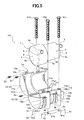
FIG. 5 is an exploded perspective view illustrating a variation example of the case of the motor-driven compressor according to the first embodiment of the present invention. - The embodiments of the present invention will be described below with reference to the appended drawings.
- First, the construction of a motor-driven
compressor 101 according to a first embodiment of the present invention will be explained. In this embodiment, the motor-drivencompressor 101 is mounted toattachment bases - Referring to
FIG. 1 , the motor-drivencompressor 101 includes a motor-driven compressormain body 1 and acase 10 surrounding the motor-driven compressormain body 1. - The motor-driven compressor
main body 1 is constituted by acompression unit 2 and adrive unit 3 that drives thecompression unit 2. - The
compression unit 2 has acompression mechanism 2a that suctions a refrigerant, which is a fluid, from the outside, compresses the refrigerant that has been suctioned, and discharges the compressed refrigerant to the outside, and acompressor housing 4 including thecompression mechanism 2a inside thereof. Thedrive unit 3 has anelectric motor 3a that receives a supply of electric power from the outside and drives thecompression mechanism 2a and amotor housing 5 including themotor 3a inside thereof. Thecompressor housing 4 and themotor housing 5 are integrated and form a single housing. In this configuration, thecompressor housing 4 constitutes a housing of thecompression unit 2. - Both the compressor housing 4 and the
motor housing 5 have a cylindrical shape and are formed from a metal such as an aluminum alloy and integrated by joining at the end portions of the cylinders. Thus, thecompressor housing 4 formed as a cylinder with a diameter larger than that of themotor housing 5 is formed by acylindrical side portion 4a, anend portion 4b that closes the end of theside portion 4a on the opposite side of themotor housing 5, and anend portion 4c that closes the end of theside portion 4a on themotor housing 5 side. Themotor housing 5 is formed by acylindrical side portion 5a, and anend portion 5c that closes the end of theside portion 5a on the opposite side of thecompressor housing 4. The end of theside portion 5a on thecompressor housing 4 side is connected to theend portion 4c of thecompressor housing 4. - The motor-driven compressor
main body 1 has asuction pipe 7 for suctioning a refrigerant from the outside on theside portion 5a of themotor housing 5 and also has adischarge pipe 8 for discharging the refrigerant compressed by thecompression mechanism 2a to the outside on theside portion 4a of thecompressor housing 4. Thesuction pipe 7 is molded integrally with themotor housing 5 and disposed on theend portion 5c side of theside portion 5a. Thedischarge pipe 8 is molded integrally with thecompressor housing 4 and disposed on theend portion 4b side of theside portion 4a. - The
case 10 includes a semicylindricalfirst case portion 11 that covers thecompressor housing 4 and themotor housing 5 from the side where thesuction pipe 7 and thedischarge pipe 8 are provided and a semicylindricalsecond case portion 12 that covers thecompressor housing 4 and themotor housing 5 from the opposite side of thefirst case portion 11. - In this configuration, the
case 10 constitutes a case, and thefirst case portion 11 and thesecond case portion 12 constitute a main body. - The
first case portion 11 and thesecond case portion 12 are put on thecompressor housing 4 and themotor housing 5 and joined together to form one substantiallycylindrical case 10 that entirely covers thecompressor housing 4 and themotor housing 5. More specifically, thefirst case portion 11 and thesecond case portion 12 are formed to cover the respective halves of theside portion 4a, halves of theend portion 4b and halves of theend portion 4c in thecompressor housing 4, and the respective halves of theside portion 5a in themotor housing 5. In other words, thecase 10 entirely covers thecompressor housing 4 and themotor housing 5 except for theend portion 5c of the motor housing 5 (seeFIG. 2 ). - Further, the
first case portion 11 and thesecond case portion 12 are formed from a resin. The resin forming thefirst case portion 11 and thesecond case portion 12 has good adhesion to metals, a good vibration damping property, that is, vibration suppression ability, and rigidity. A material with a flexural modulus of 100 MPa to 10,000 MPa can be used for the abovementioned resin. Examples of materials that can be used as the resin forming thefirst case portion 11 and thesecond case portion 12 include PP (polypropylene), PBT (polybutylene terephthalate, that is, a PBT resin), PVC (vinyl chloride resin, that is, polyvinyl chloride), PUR (polyurethanes), PTFE (fluororesin), PF (phenolic resins), PC (polycarbonates), PA (polyamides, that is, Nylon), ABS (ABS resins), carbon plastics, and mixtures thereof. Fiber-reinforced plastics (FRP) may also be used as the resin forming thefirst case portion 11 and thesecond case portion 12. - It is further preferred that a loss factor representing the vibration damping property of the resin forming the
first case portion 11 and thesecond case portion 12 be larger than that of the metal forming thecompressor housing 4 and themotor housing 5, for example, 0.01 to 1. For example, the loss factor of an aluminum alloy which is an example of the metal forming thecompressor housing 4 and themotor housing 5 is 0.0001. - Further, the
first case portion 11 is formed by a firstcompressor cover portion 11a that covers thecompressor housing 4 and a firstmotor cover portion 11b that covers themotor housing 5. - The first
compressor cover portion 11a is formed by a side cover portion 11a1 that covers theside portion 4a of thecompressor housing 4 and end cover portions 11a2 and 11a3 that respectively cover theend portions compressor housing 4. The inner sides of the side cover portion 11a1, end cover portion 11a2 and end cover portion 11a3 of the firstcompressor cover portion 11a are formed in shapes matching the shapes of the outer surfaces of theside portion 4a,end portion 4b andend portion 4c of thecompressor housing 4 which is to be covered. Further, the inner side of the firstmotor cover portion 11b is formed in a shape matching the shape of the outer surface of theside portion 5a of themotor housing 5 which is to be covered. - Further, in the side cover portion 11a1 of the first
compressor cover portion 11a in thefirst case portion 11, a through hole 11a4 for allowing thedischarge pipe 8 to protrude to the outside of thefirst case portion 11 when mounting to the motor-driven compressormain body 1 is formed. In the firstmotor cover portion 11b, a through hole 11b4 for allowing thesuction pipe 7 to protrude to the outside of thefirst case portion 11 when mounting to the motor-driven compressormain body 1 is formed. - Further, on the outer surface of the side cover portion 11a1 of the first
compressor cover portion 11a in thefirst case portion 11, a reinforcingmember 13 extending in a band-like manner along the circumferential direction of the side cover portion 11a1 is integrally provided. The reinforcingmember 13 is formed from a metal plate. Further, the reinforcingmember 13 is provided along the entire circumferential direction of the side cover portion 11a1 and hasribs 13a protruding outward from both ends of the side cover portion 11a1. Abolt hole 13b is formed through eachrib 13a. - Further, on the outer surface of the first
motor cover portion 11b in thefirst case portion 11, a reinforcingmember 15 extending in a band-like manner along the circumferential direction of the firstmotor cover portion 11b is integrally provided. The reinforcingmember 15 is formed from a metal plate. Further, the reinforcingmember 15 is provided along the entire circumferential direction of the firstmotor cover portion 11b and hasribs 15a protruding outward from both ends of the firstmotor cover portion 11b. Abolt hole 15b is formed through eachrib 15a. - The first
compressor cover portion 11a, firstmotor cover portion 11b, reinforcingmember 13 and reinforcingmember 15 are integrally formed by a resin molding method such as insert molding. - The
second case portion 12 is formed by a secondcompressor cover portion 12a that covers thecompressor housing 4 and a secondmotor cover portion 12b that covers themotor housing 5. - The second
compressor cover portion 12a is formed by a side cover portion 12a1 that covers theside portion 4a of thecompressor housing 4 and end cover portions 12a2 and 12a3 that respectively cover theend portions compressor housing 4. The inner sides of the side cover portion 12a1, end cover portion 12a2 and end cover portion 12a3 of the secondcompressor cover portion 12a are formed in shapes matching the shapes of the outer surfaces of theside portion 4a,end portion 4b andend portion 4c of thecompressor housing 4 which is to be covered. Further, the inner side of the secondmotor cover portion 12b is formed in a shape matching the shape of the outer surface of theside portion 5a of themotor housing 5 which is to be covered. - Cylindrical mounting
portions compressor cover portion 12a in thesecond case portion 12. A cylindrical mountingportion 19 is integrally formed at the side of the secondmotor cover portion 12b. - The mounting
portions 17 to 19 have similar constructions. The mountingportions 17 to 19 are respectively formed bytubular members 17a to 19a, which are cylindrical tubular bodies made from a metal, andtubular cover portions 17b to 19b constituted by a resin and formed so as to surround the cylindrical outer surface of thetubular members 17a to 19a. Thetubular cover portions compressor cover portion 12a, and thetubular cover portion 19b is integrally molded from the same material as the secondmotor cover portion 12b. Therefore, thetubular cover portions compressor cover portion 12a and form part thereof, and thetubular cover portion 19b is included in the secondmotor cover portion 12b and forms part thereof. The mountingportions 17 to 19 constitute a mounting portion. - On the outer surface of the side cover portion 12a1 of the second
compressor cover portion 12a in thesecond case portion 12, a reinforcingmember 14 extending in a band-like manner along the circumferential direction of the side cover portion 12a1 is integrally provided. The reinforcingmember 14 is formed from a metal plate. Further, the reinforcingmember 14 is provided along the entire circumferential direction of the side cover portion 12a1 and hasribs 14a protruding outward from both ends of the side cover portion 12a1. Abolt hole 14b is formed through eachrib 14a. The reinforcingmember 14 is disposed so that, when thefirst case portion 11 and thesecond case portion 12 are joined together, the bolt holes 14b of the reinforcingmember 14 are respectively aligned with the bolt holes 13b of the reinforcingmember 13 and the reinforcingmember 14 forms a single annular reinforcing member together with the reinforcingmember 13. - On the outer surface of the second
motor cover portion 12b in thesecond case portion 12, a reinforcingmember 16 extending in a band-like manner along the circumferential direction of the secondmotor cover portion 12b is integrally provided. The reinforcingmember 16 is formed from a metal plate. Further, the reinforcingmember 16 is provided along the entire circumferential direction of the secondmotor cover portion 12b and hasribs 16a protruding outward from both ends of the secondmotor cover portion 12b. Abolt hole 16b is formed thorough each therib 16a. The reinforcingmember 16 is disposed so that, when thefirst case portion 11 and thesecond case portion 12 are joined together, the bolt holes 16b of the reinforcingmember 16 are respectively aligned with the bolt holes 15b of the reinforcingmember 15 and the reinforcingmember 16 forms a single annular reinforcing member together with the reinforcingmember 15. - The second
compressor cover portion 12a, secondmotor cover portion 12b, reinforcingmember 14, reinforcingmember 16,tubular members 17a to 19a of the mountingportions 17 to 19, andtubular cover portion 17b to 19b of the mountingportions 17 to 19 are integrally formed by a resin molding method such as insert molding. - In this configuration, the reinforcing
members members - The mounting of the motor-driven
compressor 101 to the vehicle engine is performed in a state in which thecase 10 is mounted to the motor-driven compressormain body 1. In other words, the motor-drivencompressor 101 is shipped from a compressor production plant or the like to a vehicle production plant as an assembly in which thecase 10 is mounted to the motor-driven compressormain body 1, and the assembly is mounted to a vehicle engine at the vehicle production plant. - In this case, the motor-driven
compressor 101 as the assembly is assembled by covering the motor-driven compressormain body 1 with thefirst case portion 11 and thesecond case portion 12 of thecase 10, insertingbolts 52 through the bolt holes 13b and boltholes 14b and fastening thebolts 52 with anut 53 to join the reinforcingmember 13 and the reinforcingmember 14 together, and insertingbolts 52 throughbolt holes 15b and boltholes 16b and fastening thebolts 52 with anut 53 to join the reinforcingmember 15 and the reinforcingmember 16 together. As a result, thefirst case portion 11 and thesecond case portion 12 are joined together and fixed to each other. - Further, referring to
FIG. 3 , a recess 4a2 is formed in the outer surface 4a1 of theside portion 4a in thecompressor housing 4 of the motor-driven compressormain body 1. Furthermore, a protrusion 12a1b which protrudes inward and has a shape matching that of the recess 4a2 is integrally molded at an inner surface 12a1a of the side cover portion 12a1 in thesecond case portion 12 of thecase 10. Therefore, when the motor-drivencompressor 101 is assembled, the motor-driven compressormain body 1 is aligned with respect to thesecond case portion 12 by engaging the protrusion 12a1b with the recess 4a2. - Referring to
FIGS. 1 and2 , the mounting of the motor-drivencompressor 101 to the vehicle engine is performed by fixing the mountingportions case 10 to the attachment bases 61 and 62 formed integrally with the engine. More specifically,bolts portions bolts hole 61b formed in aflat attachment surface 61a of theattachment base 61, a female-threadedhole 62b formed in aflat attachment surface 62a of theattachment base 62, and a female-threadedhole 61c formed in theattachment surface 61a of theattachment base 61, thereby fixing the mountingportions compressor 101 to the engine. - Referring to
FIG. 3 , in this case, in the mountingportions compressor 101, the length of thetubular members tubular cover portions tubular member 17a respectively abut on theattachment surface 61a of theattachment base 61 and thebolt 51a and thetubular member 17a supports a compressive force created by fastening thebolt 51a. Therefore, thetubular cover portion 17b does not receive the compressive force from thebolt 51a. Ends 18a1 and 18a2 of thetubular member 18a respectively abut on theattachment surface 62a of theattachment base 62 and thebolt 51b and thetubular member 18a supports a compressive force created by fastening thebolt 51b. Therefore, thetubular cover portion 18b does not receive the compressive force from thebolt 51b. Likewise, in the mountingportion 19, thetubular member 19a supports a compressive force created by fastening thebolt 51c, and thetubular cover portion 19b does not receive the compressive force from thebolt 51c (also seeFIG. 2 ). - Further, in the side cover portion 12a1 of the
second case portion 12 in thecase 10 of the motor-drivencompressor 101, aground member 17c that extends from an inner surface 12a1a of the side cover portion 12a1 to thetubular member 17a is embedded. Theground member 17c is constituted by a wire-like or thin foil-like member made from a metal or the like, so as to have electric conductivity and flexibility similar to those of thesecond case portion 12 made from a resin. Therefore, theground member 17c electrically connects thecompressor housing 4 and thetubular member 17a. As a result, in the motor-drivencompressor 101 mounted to the attachment bases 61 and 62, thecompressor housing 4 and the motor housing 5 (seeFIG. 1 ) are electrically connected by theground member 17c and thetubular member 17a to theattachment base 61 and then to the engine and the vehicle. In this configuration, theground member 17c constitutes a conductive member. - The operation of the motor-driven
compressor 101 according to the first embodiment of the present invention will be described below. - Referring to
FIGS. 1 and2 , in the motor-drivencompressor 101, themotor 3a is actuated by supplying electric power from the outside. Thecompression mechanism 2a is thereby driven. As a result, thecompression mechanism 2a suctions a refrigerant from a refrigeration circuit of the vehicle (not shown) through thesuction pipe 7. The refrigerant that has been suctioned passes inside through themotor housing 5 and is suctioned to thecompression mechanism 2a of thecompressor housing 4. Further, the refrigerant is compressed by thecompression mechanism 2a and then discharged from thedischarge pipe 8 to the refrigeration circuit. The refrigeration circuit is provided with the motor-drivencompressor 101 and also a condenser, an expansion valve and an evaporator (not shown). - In this case, operational noise generated in the
operating motor 3a is emitted through themotor housing 5, and vibrations of themotor 3a also induce vibrations in themotor housing 5. Further, the operational noise generated in theoperating compression mechanism 2a is emitted through thecompression housing 4, and vibrations of thecompression mechanism 2a also induce vibrations in thecompressor housing 4. - The first
motor cover portion 11b and the secondmotor cover portion 12b that are made from a resin in thecase 10 cover theentire side portion 5a occupying most of the surface area of themotor housing 5. Therefore, emission of the operational noise from themotor housing 5 can be inhibited in a wide region of themotor housing 5. - Furthermore, referring also to
FIG. 3 , vibrations of themotor housing 5 generated when themotor 3a operates are transmitted to the firstmotor cover portion 11b and the secondmotor cover portion 12b of thecase 10 adjacent to themotor housing 5. - Since the first
motor cover portion 11b and the secondmotor cover portion 12b that are made from a resin have a large loss factor, the vibrations transmitted to the firstmotor cover portion 11b and the secondmotor cover portion 12b are attenuated therein, thereby suppressing the transmission of the vibrations to thetubular member 19a that is in contact with thetubular cover portion 19b formed integrally with the secondmotor cover portion 12b. Further, even though thetubular cover portion 19b is in contact with thebolt 51c or theattachment base 61, since the vibrations transmitted to thetubular cover portion 19b are attenuated, the transmission thereof to thebolt 51c and theattachment base 61 is suppressed. - As a result, the operational noise and vibrations generated in the
motor 3a are significantly less than those of thecompression mechanism 2a, but the operational noise emitted from themotor housing 5 can be suppressed to an even lower level and the resonance noise generated due to the transmission of vibrations of themotor housing 5 to the vehicle through the engine (not shown) can be suppressed to an even lower level. - Further, returning to
FIGS. 1 and2 , when thecompression mechanism 2a is actuated, operational noise and vibrations are generated, but large operational noise and vibrations are generated when the compressed refrigerant is discharged on the discharge side thereof. - The first
compressor cover portion 11a and the secondcompressor cover portion 12a that are made from a resin in thecase 10 cover the entire surface of thecompressor housing 4. Therefore, the emission of operational noise generated by thecompression mechanism 2a is suppressed over the entire region of thecompressor housing 4. In particular, strong operational noise generated on the discharge side close to thedischarge pipe 8 is effectively prevented from being emitted to the outside since theend portion 4b and theside portion 4a of thecompressor housing 4 are covered by the firstcompressor cover portion 11a and the secondcompressor cover portion 12a. - Further, referring also to
FIG. 3 , the vibrations of thecompressor housing 4 generated during thecompression mechanism 2a operating are transmitted to the firstcompressor cover portion 11a and the secondcompressor cover portion 12a of thecase 10 adjacent to thecompressor housing 4. - The vibrations transmitted to the first
compressor cover portion 11a and the secondcompressor cover portion 12a that are made from a resin are attenuated therein and the transmission of the vibrations to thetubular members tubular cover portions compressor cover portion 12a is suppressed. Further, even though thetubular cover portions bolt attachment base tubular cover portion bolts - As a result, the operational noise emitted from the
compressor housing 4 is reduced and the resonance noise generated due to the transmission of vibrations of thecompressor housing 4 to the vehicle through the engine (not shown) is reduced. - Further, since the first
compressor cover portion 11a and the secondcompressor cover portion 12a are formed from a resin with a flexural modulus of 100 MPa to 10,000 MPa and have a high rigidity, the deformation occurring in the firstcompressor cover portion 11a, secondcompressor cover portion 12a and alsotubular cover portions compressor housing 4 are suppressed. As a result, the displacement of the motor-driven compressormain body 1 with respect to the attachment bases 61 and 62 is suppressed and the increase in the amplitude of vibrations of the motor-driven compressormain body 1 is inhibited. - As described hereinabove, the motor-driven
compressor 101 in accordance with the present invention is configured to be mounted to the attachment bases 61 and 62 of a vehicle engine. The motor-drivencompressor 101 includes acompression unit 2 that compresses a refrigerant suctioned from outside and then discharges the compressed refrigerant; anelectric drive unit 3 that drives thecompression unit 2; and acase 10 which has afirst case portion 11 and asecond case portion 12 that are formed from a resin and cover at least thecompression unit 2 and mountingportions second case portion 12 and configured to be mounted to the attachment bases 61, 62. The mountingportions members second case portion 12, andbolts tubular members tubular members second case portion 12 is interposed between thecompression unit 2 and thetubular members - In this case, the
tubular cover portions second case portion 12 constituted by a resin with a good vibration damping property are interposed between thetubular members compressor housing 4 of thecompression unit 2. As a result, all the vibrations generated from thecompressor housing 4 are transmitted to thetubular members first case portion 11,second case portion 12 andtubular cover portions first case portion 11,second case portion 12 andtubular cover portions compressor 101 to the engine, that is, to the vehicle, through the attachment bases 61, 62 can be reduced, thereby making it possible to reduce resonance noise in the vehicle. Further, since thecase 10 covers at least thecompressor housing 4 by thefirst case portion 11 and thesecond case portion 12 made from a resin, the emission of operational noise of thecompression mechanism 2a from thecompressor housing 4 can be reduced. Therefore, in the motor-drivencompressor 101, both the resonance noise generated due to the transmission of vibrations to the vehicle where the motor-drivencompressor 101 is installed and the emission noise generated due to the emission of operational noise of thecompression mechanism 2a from thecompressor housing 4 can be reduced. - Since the noise can be effectively reduced in the motor-driven
compressor 101, the motor-drivencompressor 101 can be configured to use high-speed operation by utilizing a small-capacity compression mechanism 2a. As a result, the motor-drivencompressor 101 can be reduced in size and cost. - Furthermore, in the motor-driven
compressor 101, thecompressor housing 4 andmotor housing 5 are separated from the mountingportions compressor housing 4 and themotor housing 5 to match the arrangement of the attachment bases 61 and 62 and a common housing can be used for installation on various vehicles with different arrangements of attachment bases 61 and 62, thereby making it possible to reduce cost. - Further, the motor-driven
compressor 101 is configured such that thecompressor housing 4 and themotor housing 5 which are accommodated in thecase 10 are mounted to the attachment bases 61 and 62, and the mountingportions case 10. Therefore, thecompressor housing 4 and themotor housing 5 can have a simple shape such as a cylindrical shape. By simplifying the shape of thecompressor housing 4 and themotor housing 5 made from an aluminum alloy, it is possible to reduce cavities which appear during casting of the aluminum alloy and pass through thecompressor housing 4 and themotor housing 5, thereby improving the quality of thecompressor housing 4 and themotor housing 5. - Further, in the motor-driven
compressor 101, by changing the type of the resin constituting thecase 10, thefirst case portion 11,second case portion 12 andtubular cover portions compressor 101 is installed. - Further, in the motor-driven
compressor 101, the resin forming thefirst case portion 11 and thesecond case portion 12 has a vibration damping property superior to the vibration damping property of the material forming thecompressor housing 4 of thecompression unit 2. As a result, the vibrations transmitted from thecompressor housing 4 to thefirst case portion 11 and thesecond case portion 12 can be effectively attenuated. - Further, in the motor-driven
compressor 101, thefirst case portion 11 and thesecond case portion 12 can be joined to and separated from each other, and thecase 10 has reinforcingmembers 13 to 16 for fixing together thefirst case portion 11 and thesecond case portion 12 that have been joined together. As a result, the operation of mounting thecase 10 to the motor-driven compressormain body 1 can be facilitated. - Further, in the motor-driven
compressor 101, the reinforcingmembers first case portion 11, and the reinforcingmembers second case portion 12. Furthermore, where the reinforcingmembers members members 13 to 16 fix thefirst case portion 11 and thesecond case portion 12 that have been joined together and surround the periphery of the abovefirst case portion 11 andsecond case portion 12. As a result, the reinforcingmembers 13 to 16 increase the strength of thefirst case portion 11 and thesecond case portion 12 made from a resin and also increase the joining strength thereof, thereby making it possible to prevent thefirst case portion 11 and thesecond case portion 12 from deformation and damage caused by the vibrations of thecompression unit 2 and thedrive unit 3. - In the motor-driven
compressor 101, thetubular members bolts bolts tubular cover portions second case portion 12 to prevent the compressive force created by thebolts tubular cover portions tubular cover portions bolts tubular members - In the motor-driven
compressor 101, thesecond case portion 12 integrally includes the flexible andconductive ground member 17c which electrically connects thetubular member 17a to thecompression unit 2 located inside thefirst case portion 11 and thesecond case portion 12. In this case, where thetubular member 17a is made from a metal, by merely mounting the motor-drivencompressor 101 where the motor-driven compressormain body 1 is accommodated in thecase 10 to the attachment bases 61 and 62, thecompressor housing 4 can be electrically connected to theattachment base 61, that is, to the vehicle, by theground member 17c and thetubular member 17a. As a result, when the motor-drivencompressor 101 is installed on a vehicle, the operation of leading out a ground cable is unnecessary and the number of operations is reduced, thereby reducing cost. - Further, in the motor-driven
compressor 101, thefirst case portion 11 and thesecond case portion 12 also cover at least part of thedrive unit 3. As a result, thefirst case portion 11 and thesecond case portion 12 can suppress the emission of operational noise of themotor 3a from themotor housing 5, and the noise generated by the motor-drivencompressor 101 can be further reduced. - A motor-driven
compressor 201 according to a second embodiment of the present invention has a construction where thefirst case portion 11 and thesecond case portion 12 of thecase 10, which cover thecompressor housing 4 and themotor housing 5 in the motor-drivencompressor 101 of the first embodiment, are modified so as to cover only thecompressor housing 4. - In the below-described embodiment, reference numerals identical to those in the above-mentioned drawings denote same or similar constituent elements. Therefore, detailed explanation thereof is herein omitted.
- Referring to
FIG. 4 , acase 210 of the motor-drivencompressor 201 includes afirst case portion 211 and asecond case portion 212 similarly to the motor-drivencompressor 101 of the first embodiment, but thefirst case portion 211 and thesecond case portion 212 are formed to cover the respective halves of theside portion 4a, halves of theend portion 4b and halves of theend portion 4c in thecompressor housing 4. Further, the inner sides of a side cover portion 211a1, an end cover portion 211a2 and an end cover portion 211a3 of thefirst case portion 211 are formed in a shape matching the shape of the outer surface of theside portion 4a,end portion 4b andend portion 4c of thecompressor housing 4 to be covered. The inner sides of a side cover portion 212a1, an end cover portion 212a2, and an end cover portion 212a3 of thesecond case portion 212 are formed in a shape matching the shape of the outer surface of theside portion 4a,end portion 4b andend portion 4c of thecompressor housing 4 to be covered. - Further, the reinforcing
member 13 is integrally provided on the outer surface of the side cover portion 211a1 of thefirst case portion 211, and the reinforcingmember 14 is integrally provided on the outer surface of the side cover portion 212a1 of thesecond case portion 212. A through hole 211a4 for allowing thedischarge pipe 8 to protrude out of thefirst case portion 211 is formed in the side cover portion 211a1 of thefirst case portion 211. - The mounting
portions 17 and 18 (seeFIG. 1 ) are integrally formed on both sides of the side cover portion 212a1 of thesecond case portion 212. - A cylindrical mounting
portion 220 extending in the same direction as the mountingportions 17 and 18 (seeFIG. 1 ) is disposed to abut on theend portion 5c of themotor housing 5. The mountingportion 220 is connected to thefirst case portion 211 and thesecond case portion 212 byresin connection members portion 220 is constituted by afirst mounting component 221 and asecond mounting component 222 that can be connected to each other and separated from each other in the axial direction of cylinder. In this configuration, the mountingportion 220 constitutes a second mounting portion. - The
first mounting component 221 and thesecond mounting component 222 are respectively formed by cylindricaltubular members tubular cover portions tubular members tubular member 221a protrudes from thetubular cover portion 221b at thesecond mounting component 222 side, and thetubular member 222a is shorter than thetubular cover portion 222b at thefirst mounting component 221 side. As a result, thefirst mounting component 221 and thesecond mounting component 222 are connected to each other when thetubular member 221a is fit into thetubular cover portion 222b. In this configuration, thetubular members tubular cover portions - The
connection member 211b is molded integrally with and connects thefirst case portion 211 and thetubular cover portion 221b so that, when thecase 210 is mounted to the motor-driven compressormain body 1, theconnection member 211b extends along theside portion 5a of themotor housing 5. Theconnection member 212b is molded integrally with and connects thesecond case portion 212 and thetubular cover portion 222b so that, when thecase 210 is mounted to the motor-driven compressormain body 1, theconnection member 212b extends along theside portion 5a of themotor housing 5. Theconnection members motor housing 5 when thecase 210 is fixed to the motor-driven compressormain body 1. - Further, the
first case portion 211, reinforcingmember 13,connection member 211b, and thetubular member 221a and thetubular cover portion 221b of thefirst mounting component 221 are formed integrally by a resin molding method such as insert molding. Further, thesecond case portion 212, thetubular members FIG. 1 ) and thetubular cover portions FIG. 1 ) of the mountingportions member 14,connection member 212b, and thetubular member 222a and thetubular cover portion 222b of thesecond mounting component 222 are formed integrally by a resin molding method such as insert molding. - Therefore, the motor-driven
compressor 201 is assembled by covering thecompressor housing 4 of the motor-driven compressormain body 1 with thefirst case portion 211 and thesecond case portion 212 of thecase 210, fastening together the reinforcingmembers bolts 52 andnuts 53, and fitting thefirst mounting component 221 with thesecond mounting component 222. - Further, the mounting of the assembled motor-driven
compressor 201 to the attachment bases 61 and 62 (seeFIG. 1 ) is performed by respectively inserting thebolts FIG. 1 ) and 51c into thetubular member 17a of the mountingportion 17, thetubular member 18a (seeFIG. 1 ) of the mountingportion 18, and thetubular members portion 220, and further fastening thebolts hole 61b of theattachment base 61, the female-threadedhole 62b (seeFIG. 1 ) of theattachment base 62 and the female-threadedhole 61c of theattachment base 61. In this case, thebolt 51c constitutes a second fastening member. - During operation of the motor-driven
compressor 201, thecase 210 suppresses the emission of operational noise from thecompressor housing 4 to the outside and also suppresses the transmission of vibrations of thecompressor housing 4 to the attachment bases 61 and 62 (seeFIG. 1 ) by thetubular members bolts FIG. 1 ), in the same manner as thecase 10 of the first embodiment. - Other features and operations of the motor-driven
compressor 201 according to the second embodiment of the present invention are similar to those of the first embodiment and the explanation thereof is herein omitted. - As described hereinabove, the effects obtained with the motor-driven
compressor 201 of the second embodiment are similar to those obtained with the motor-drivencompressor 101 of the aforementioned first embodiment. - Further, in the motor-driven
compressor 201, thecase 210 includes the mountingportion 220 that is provided in contact with thedrive unit 3 and separately from thefirst case portion 211 and thesecond case portion 212. The mountingportion 220 has thetubular members tubular cover portions tubular members tubular members drive unit 3, thebolt 51c inserted into thetubular members tubular members attachment base 61, and theconnection members tubular members first case portion 211 and thesecond case portion 212. As a result, noise generated in thecompression unit 2 that has high operational noise and large vibrations can be reduced, whereas, since themotor housing 5 of thedrive unit 3 that has low operational noise and small vibrations is not covered by thecase 210, heat generated by themotor 3a therein can be dissipated thereby making it possible to increase durability of themotor 3a. - Further, in the motor-driven
compressors first case portions second case portions FIG. 5 , for example, the motor-drivencompressor 101 may have a construction where arib 13a and abolt hole 13b are formed only at one end of the reinforcingmember 13 provided at the firstcompressor cover portion 11a of thefirst case portion 11, arib 14a and abolt hole 14b are formed only at one end of the reinforcingmember 14 provided at the secondcompressor cover portion 12a of thesecond case portion 12, and the other end of the reinforcingmember 13 and the other end of the reinforcingmember 14 are connected to each other with ahinge 313c. Also, the reinforcingmembers members compressor 101 in which thecase 10 is mounted to the motor-driven compressormain body 1 can be further facilitated. - Further, in the motor-driven
compressors cases first case portions second case portions cases main body 1 is inserted into thecase main body 1 may also be fixed to thecase case case main body 1. - Further, in the mounting
portions compressors bolts metal tubular members tubular members compressor housing 4 and themotor housing 5 and a compressive strength capable of withstanding the compressive force created by fastening thebolts resin tubular members portions second case portion 12 may be configured as a single member made from the same resin material. As a result, the number of parts is decreased and therefore the cost can be reduced. - Further, in the mounting
portions compressors tubular cover portions tubular members portions tubular cover portions second case portion 12 at least between thetubular members compressor housing 4 ormotor housing 5. Further, in the case of the mountingportion 220, thetubular cover portions tubular members motor housing 5. - Further, in the motor-driven
compressors main body 1 with thesecond case portion case compressor housing 4 and the protrusion 12a1b is formed at thesecond case portion - Further, in the motor-driven
compressors members 13 to 16 fix the joinedfirst case portion second case portion first case portion second case portion first case portion second case portion - Further, in the motor-driven
compressors members 13 to 16 are provided on the outer surfaces of thefirst case portions second case portions members 13 to 16 may also be provided inside or on the inner surfaces of thefirst case portions second case portions - Further, in the motor-driven
compressor 201 of the second embodiment, theconnection members connection members metal connection members member 13 to thetubular member 221a, and the reinforcingmember 14 to thetubular member 222a. - Further, in the motor-driven
compressor 201 of the second embodiment, thetubular cover portions portion 220 are configured to abut on theend portion 5c of themotor housing 5, but such configuration is not limiting, and theend portion 5c of themotor housing 5 may be fit over thetubular cover portions motor housing 5 is supported not only by theconnection members portion 220 and can be fixed more strongly. - Further, the
cases compressors cases
A motor-driven compressor (101) mounted to attachment bases (61, 62) includes a refrigerant compression unit (2), an electric drive unit (3) for the compression unit (2) and a case (10). The case (10) has first and second case portions (11, 12) formed from a resin, which cover at least the compression unit (2). The case (10) also has mounting portions (17, 18, 19) that are provided integrally with the second case portion (12) and configured to be mounted to the attachment bases (61, 62). The mounting portions (17, 18, 19) respectively have tubular members (17a, 18a, 19a) and bolts (51a, 51b, 51c) inserted through the tubular members (17a, 18a, 19a) for mounting them to the attachment bases (61, 62). The second case portion (12) is interposed between the compression unit (2) and the tubular members (17a, 18a, 19a).
Claims (8)
- A motor-driven compressor (101; 201) to be mounted to an attachment section (61, 62) of a vehicle, comprising:a compression unit (2) that compresses a fluid suctioned from outside and then discharges the compressed fluid; andan electric drive unit (3) that drives the compression unit (2), characterized by further comprisinga case (10; 210) having a main body (11, 12; 211, 212) formed from a resin and covering at least the compression unit (2), and a mounting portion (17, 18, 19) that is provided integrally with the main body (11, 12; 211, 212) and configured to be mounted to the attachment section (61, 62),wherein the mounting portion (17, 18, 19) has:a tubular body (17a, 18a, 19a) provided integrally with the main body (11, 12; 211, 212); anda fastening member (51a, 51b, 51c) inserted into the tubular body (17a, 18a, 19a) for mounting the tubular body (17a, 18a, 19a) to the attachment section (61, 62), andthe main body (11, 12; 211, 212) is interposed between the compression unit (2) and the tubular body (17a, 18a, 19a).
- The motor-driven compressor (101; 201) according to claim 1, characterized in that the resin forming the main body (11, 12; 211, 212) has a vibration damping property superior to a vibration damping property of a material forming a housing (4) of the compression unit (2).
- The motor-driven compressor (101; 201) according to claim 1 or 2, characterized in that the main body (11, 12; 211, 212) is constituted by a first case portion (11; 211) and a second case portion (12; 212) that can be joined to and separated from each other, and that the case (10; 210) has a fixture (13, 14, 15, 16) for fixing to each other the first case portion (11; 211) and the second case portion (12; 212) that have been joined together.
- The motor-driven compressor (101; 201) according to claim 3, characterized in that the fixture (13, 14, 15, 16) is constituted by a first fixture (13, 15) made from a metal and provided at the first case portion (11; 211) and a second fixture (14, 16) made from a metal and provided at the second case portion (12; 212), and that the first fixture (13, 15) and the second fixture (14, 16) are connected to each other to fix the first case portion (11; 211) and the second case portion (12; 212) that have been joined together and surround the periphery of the first case portion (11; 211) and the second case portion (12; 212) that have been joined together.
- The motor-driven compressor (101; 201) according to any one of claims 1-4, characterized in that the tubular body (17a, 18a, 19a) is made from a metal and supports a fastening force created by the fastening member (51a, 51b, 51c) between the attachment section (61, 62) and the fastening member (51a, 51b, 51c).
- The motor-driven compressor (101; 201) according to any one of claims 1-5, characterized in that the main body (12; 212) integrally includes a conductive member (17c) that is flexible and conducive and electrically connects the tubular body (17a) and the compression unit (2) in the main body (12; 212).
- The motor-driven compressor (101) according to any one of claims 1-6, characterized in that the main body (11, 12) further covers at least part of the drive unit (3).
- The motor-driven compressor (201) according to any one of claims 1-7, characterized in that the case (210) has a second mounting portion (220) that is provided in contact with the drive unit (3) separately from the main body (211, 212), and that the second mounting portion (220) has:a second tubular body (221a, 222a);a resin member (221b, 222b) provided integrally with the second tubular body (221a, 222a) so as to be interposed between the second tubular body (221a, 222a) and the drive unit (3);a second fastening member (51c) inserted into the second tubular body (221a, 222a) for mounting the second tubular body (221a, 222a) to the attachment section (61); anda connection member (211b, 212b) that connects the second tubular body (221a, 222a) and the main body (211, 212).
Applications Claiming Priority (1)
| Application Number | Priority Date | Filing Date | Title |
|---|---|---|---|
| JP2011070324A JP5609736B2 (en) | 2011-03-28 | 2011-03-28 | Electric compressor |
Publications (2)
| Publication Number | Publication Date |
|---|---|
| EP2505394A1 true EP2505394A1 (en) | 2012-10-03 |
| EP2505394B1 EP2505394B1 (en) | 2014-05-14 |
Family
ID=45939176
Family Applications (1)
| Application Number | Title | Priority Date | Filing Date |
|---|---|---|---|
| EP12161255.0A Active EP2505394B1 (en) | 2011-03-28 | 2012-03-26 | Motor-driven compressor |
Country Status (5)
| Country | Link |
|---|---|
| US (1) | US9273683B2 (en) |
| EP (1) | EP2505394B1 (en) |
| JP (1) | JP5609736B2 (en) |
| KR (1) | KR101350121B1 (en) |
| CN (1) | CN102705196B (en) |
Cited By (2)
| Publication number | Priority date | Publication date | Assignee | Title |
|---|---|---|---|---|
| EP4124483A1 (en) * | 2021-07-29 | 2023-02-01 | Vibracoustic SE | Mounting for fixing an electric compressor |
| EP4553318A4 (en) * | 2022-07-05 | 2026-04-15 | Byd Co Ltd | Covering body, compressor and vehicle |
Families Citing this family (28)
| Publication number | Priority date | Publication date | Assignee | Title |
|---|---|---|---|---|
| JP5273084B2 (en) * | 2010-03-31 | 2013-08-28 | 株式会社豊田自動織機 | Electric compressor |
| JP5482387B2 (en) * | 2010-03-31 | 2014-05-07 | 株式会社豊田自動織機 | Electric compressor |
| JP5556721B2 (en) * | 2011-03-28 | 2014-07-23 | 株式会社豊田自動織機 | Electric compressor |
| DE202011108871U1 (en) * | 2011-12-09 | 2013-03-13 | Gardner Denver Schopfheim Gmbh | pump |
| JP6020148B2 (en) * | 2012-03-20 | 2016-11-02 | 株式会社豊田自動織機 | Electric compressor |
| CN204902188U (en) * | 2012-08-17 | 2015-12-23 | 特灵国际有限公司 | Soundproof enclosures for compressors and refrigeration systems including compressors and soundproof enclosures |
| JP6094497B2 (en) * | 2014-01-20 | 2017-03-15 | 株式会社豊田自動織機 | Electric compressor and method for manufacturing electric compressor |
| US10731648B2 (en) | 2014-11-07 | 2020-08-04 | Trane International Inc. | Sound control for a heating, ventilation, and air conditioning unit |
| US10443644B2 (en) * | 2015-02-09 | 2019-10-15 | Syntiro Dynamics Llc | Anchor sealing hygienic bracket |
| CN104786778B (en) * | 2015-04-08 | 2017-03-15 | 奇瑞汽车股份有限公司 | A kind of automobile air conditioner compressor fixing device |
| DE102016120579B3 (en) * | 2016-10-27 | 2018-04-05 | Klaus Union Gmbh & Co. Kg | Horizontally split screw pump |
| FR3059746B1 (en) * | 2016-12-05 | 2020-08-28 | Valeo Japan Co Ltd | COMPRESSOR FOR AN AIR CONDITIONING PLANT EQUIPPED WITH VIBRATION DAMPING UNITS |
| KR102485662B1 (en) | 2017-02-17 | 2023-01-09 | 한온시스템 주식회사 | Compressor |
| JP6748048B2 (en) * | 2017-10-10 | 2020-08-26 | Ckd株式会社 | Portable compressed air feeder |
| JP7005298B2 (en) * | 2017-11-09 | 2022-01-21 | 三菱重工サーマルシステムズ株式会社 | Electric compressor for vehicles |
| DE102018000667B4 (en) * | 2018-01-29 | 2021-11-04 | Truma Gerätetechnik GmbH & Co. KG | Air conditioner |
| JP2020133408A (en) * | 2019-02-13 | 2020-08-31 | 太平洋工業株式会社 | Compressor cover |
| US12110910B2 (en) | 2019-03-25 | 2024-10-08 | Mitsubishi Heavy Industries Thermal Systems, Ltd. | Compressor for automobile air conditioning device |
| JP2021148104A (en) * | 2020-03-23 | 2021-09-27 | 三菱重工サーマルシステムズ株式会社 | Compressor |
| CN112664431B (en) * | 2020-12-15 | 2024-09-27 | 珠海格力电器股份有限公司 | Compressor vibration damper and air conditioner |
| JP7468384B2 (en) | 2021-01-29 | 2024-04-16 | 株式会社豊田自動織機 | Electric Compressor |
| JP7488986B2 (en) * | 2021-03-23 | 2024-05-23 | 株式会社豊田自動織機 | Electric Compressor |
| KR102703441B1 (en) * | 2021-06-04 | 2024-09-06 | 엘지전자 주식회사 | Compressor |
| JP7652106B2 (en) * | 2022-03-09 | 2025-03-27 | 株式会社豊田自動織機 | Electric Compressor |
| US20250271931A1 (en) * | 2022-05-04 | 2025-08-28 | Hatpx, Inc. | Haptic glove system and manufacture of haptic glove systems |
| CN114837917A (en) * | 2022-06-07 | 2022-08-02 | 江苏上菱智能电器有限公司 | Refrigerator noise reduction device and using method thereof |
| CN115059602B (en) * | 2022-07-15 | 2025-08-26 | 浙江冰峰压缩机有限公司 | Compressor plastic shell and compressor |
| KR102868078B1 (en) * | 2022-08-01 | 2025-10-14 | 두원중공업(주) | Bolt sealing cap for compressor soundproof cover |
Citations (7)
| Publication number | Priority date | Publication date | Assignee | Title |
|---|---|---|---|---|
| JPS6444810A (en) | 1987-08-12 | 1989-02-17 | Shimizu Construction Co Ltd | Measuring system of form |
| JPS6444810U (en) * | 1987-09-14 | 1989-03-17 | ||
| EP0904962A2 (en) * | 1997-09-25 | 1999-03-31 | Denso Corporation | Mounting structure of electric motor-driven compressor |
| US20020131878A1 (en) * | 2001-03-14 | 2002-09-19 | Matsushita Electric Industrial Co. Ltd. | Compressor with built-in motor mounted on engine of mobile structure |
| US20030156951A1 (en) * | 2002-02-15 | 2003-08-21 | Hirokazu Kamiya | Compressor |
| US20080314072A1 (en) * | 2005-10-14 | 2008-12-25 | Truma Geratetechnik Gmbh & Co. Kg | Air-Conditioning Unit for Mobile Devices |
| US20110243767A1 (en) * | 2010-03-31 | 2011-10-06 | Kabushiki Kaisha Toyota Jidoshokki | Motor-driven compressor |
Family Cites Families (24)
| Publication number | Priority date | Publication date | Assignee | Title |
|---|---|---|---|---|
| JPS5545084U (en) * | 1978-09-19 | 1980-03-24 | ||
| JPS5545084A (en) | 1978-09-26 | 1980-03-29 | Tokyo Optical Co Ltd | High resolution lens |
| JPS6365873U (en) | 1986-10-17 | 1988-04-30 | ||
| JPS6444812U (en) | 1987-09-14 | 1989-03-17 | ||
| DE3869528D1 (en) * | 1987-09-14 | 1992-04-30 | Sanden Corp | MOUNTING A VEHICLE COMPRESSOR FOR AN AIR CONDITIONING. |
| JPS6444815U (en) | 1987-09-14 | 1989-03-17 | ||
| IT238524Y1 (en) * | 1997-02-26 | 2000-11-13 | Zcm Srl | PERFECTED PIPE CLAMP |
| JP4066537B2 (en) * | 1998-10-28 | 2008-03-26 | 株式会社デンソー | Electric compressor mounting structure |
| JP4053195B2 (en) * | 1999-08-30 | 2008-02-27 | サンデン株式会社 | Compressor mounting structure |
| EP1128086A2 (en) * | 2000-02-28 | 2001-08-29 | Tokai Rubber Industries, Ltd. | Vibration-damping device for vehicles |
| JP2003136948A (en) | 2001-11-06 | 2003-05-14 | Nippon Soken Inc | Mounting device for vertical electric compressor |
| EP1363026A3 (en) * | 2002-04-26 | 2004-09-01 | Denso Corporation | Invertor integrated motor for an automotive vehicle |
| JP3804589B2 (en) * | 2002-07-15 | 2006-08-02 | 株式会社豊田自動織機 | Electric compressor |
| JP2005220855A (en) | 2004-02-06 | 2005-08-18 | Toyota Industries Corp | Motor-driven compressor mounting structure |
| JP2005220854A (en) | 2004-02-06 | 2005-08-18 | Toyota Industries Corp | Motor-driven compressor mounting structure |
| JP2005220856A (en) | 2004-02-06 | 2005-08-18 | Toyota Industries Corp | Motor-driven compressor mounting structure |
| JP2006064046A (en) * | 2004-08-26 | 2006-03-09 | Yazaki Corp | Fixed structure |
| WO2007070271A1 (en) * | 2005-12-09 | 2007-06-21 | Erico International Corporation | Clamp for circular objects |
| JP2008088958A (en) * | 2006-10-05 | 2008-04-17 | Matsushita Electric Ind Co Ltd | Refrigerant compressor |
| JP2009074386A (en) * | 2007-09-19 | 2009-04-09 | Sanden Corp | Compressor |
| JP4764395B2 (en) * | 2007-09-21 | 2011-08-31 | 三菱重工業株式会社 | Inverter-integrated electric compressor |
| JP2010138808A (en) * | 2008-12-11 | 2010-06-24 | Denso Corp | Component mounting structure |
| US9038968B2 (en) * | 2009-06-09 | 2015-05-26 | John HENNON | Attachable grommets for hanging pipes |
| JP5315178B2 (en) * | 2009-09-08 | 2013-10-16 | 日立アプライアンス株式会社 | Hermetic compressor and refrigerator using the same |
-
2011
- 2011-03-28 JP JP2011070324A patent/JP5609736B2/en active Active
-
2012
- 2012-03-23 KR KR1020120029770A patent/KR101350121B1/en not_active Expired - Fee Related
- 2012-03-26 EP EP12161255.0A patent/EP2505394B1/en active Active
- 2012-03-26 CN CN201210082737.3A patent/CN102705196B/en not_active Expired - Fee Related
- 2012-03-28 US US13/432,679 patent/US9273683B2/en active Active
Patent Citations (7)
| Publication number | Priority date | Publication date | Assignee | Title |
|---|---|---|---|---|
| JPS6444810A (en) | 1987-08-12 | 1989-02-17 | Shimizu Construction Co Ltd | Measuring system of form |
| JPS6444810U (en) * | 1987-09-14 | 1989-03-17 | ||
| EP0904962A2 (en) * | 1997-09-25 | 1999-03-31 | Denso Corporation | Mounting structure of electric motor-driven compressor |
| US20020131878A1 (en) * | 2001-03-14 | 2002-09-19 | Matsushita Electric Industrial Co. Ltd. | Compressor with built-in motor mounted on engine of mobile structure |
| US20030156951A1 (en) * | 2002-02-15 | 2003-08-21 | Hirokazu Kamiya | Compressor |
| US20080314072A1 (en) * | 2005-10-14 | 2008-12-25 | Truma Geratetechnik Gmbh & Co. Kg | Air-Conditioning Unit for Mobile Devices |
| US20110243767A1 (en) * | 2010-03-31 | 2011-10-06 | Kabushiki Kaisha Toyota Jidoshokki | Motor-driven compressor |
Cited By (3)
| Publication number | Priority date | Publication date | Assignee | Title |
|---|---|---|---|---|
| EP4124483A1 (en) * | 2021-07-29 | 2023-02-01 | Vibracoustic SE | Mounting for fixing an electric compressor |
| CN115675017A (en) * | 2021-07-29 | 2023-02-03 | 威巴克欧洲股份公司 | Support for fixing electric compressor |
| EP4553318A4 (en) * | 2022-07-05 | 2026-04-15 | Byd Co Ltd | Covering body, compressor and vehicle |
Also Published As
| Publication number | Publication date |
|---|---|
| US20120251357A1 (en) | 2012-10-04 |
| JP5609736B2 (en) | 2014-10-22 |
| KR101350121B1 (en) | 2014-01-09 |
| US9273683B2 (en) | 2016-03-01 |
| CN102705196B (en) | 2015-07-08 |
| CN102705196A (en) | 2012-10-03 |
| KR20120110024A (en) | 2012-10-09 |
| EP2505394B1 (en) | 2014-05-14 |
| JP2012202377A (en) | 2012-10-22 |
Similar Documents
| Publication | Publication Date | Title |
|---|---|---|
| EP2505394B1 (en) | Motor-driven compressor | |
| EP2743109B1 (en) | Motor-driven compressor | |
| JP5273084B2 (en) | Electric compressor | |
| US12129855B2 (en) | Sound absorbing cover and vibration insulating support for an electric compressor | |
| US8714943B2 (en) | Mounting and damping system for a compressor | |
| US8770948B2 (en) | Motor-driven compressor | |
| US20130017100A1 (en) | Motor-driven compressor | |
| US8647080B2 (en) | Motor-driven compressor | |
| US20110243765A1 (en) | Motor-driven compressor | |
| US20110147150A1 (en) | Attachment arrangement for a refrigerant compressor | |
| CN103998781B (en) | Inlet/Outlet Pipe Reinforcement for Vehicle Compressors | |
| CN219774667U (en) | Low-rigidity bushing | |
| CN107461338B (en) | Compressor with a compressor housing having a plurality of compressor blades | |
| CN216942602U (en) | Suspension assembly and car | |
| CN118269590A (en) | Mounting bracket, mounting assembly, air conditioning unit and vehicle | |
| CN222526460U (en) | Compressor fixing structure and vehicle | |
| CN220037354U (en) | Single-stage vibration isolation compressor suspension bracket laterally mounted on new energy vehicle | |
| KR20200031583A (en) | Motor driven compressor |
Legal Events
| Date | Code | Title | Description |
|---|---|---|---|
| PUAI | Public reference made under article 153(3) epc to a published international application that has entered the european phase |
Free format text: ORIGINAL CODE: 0009012 |
|
| 17P | Request for examination filed |
Effective date: 20120326 |
|
| AK | Designated contracting states |
Kind code of ref document: A1 Designated state(s): AL AT BE BG CH CY CZ DE DK EE ES FI FR GB GR HR HU IE IS IT LI LT LU LV MC MK MT NL NO PL PT RO RS SE SI SK SM TR |
|
| AX | Request for extension of the european patent |
Extension state: BA ME |
|
| GRAP | Despatch of communication of intention to grant a patent |
Free format text: ORIGINAL CODE: EPIDOSNIGR1 |
|
| INTG | Intention to grant announced |
Effective date: 20131129 |
|
| RIN1 | Information on inventor provided before grant (corrected) |
Inventor name: SUITOU, KEN Inventor name: YOKOI, KENJI |
|
| GRAS | Grant fee paid |
Free format text: ORIGINAL CODE: EPIDOSNIGR3 |
|
| GRAA | (expected) grant |
Free format text: ORIGINAL CODE: 0009210 |
|
| AK | Designated contracting states |
Kind code of ref document: B1 Designated state(s): AL AT BE BG CH CY CZ DE DK EE ES FI FR GB GR HR HU IE IS IT LI LT LU LV MC MK MT NL NO PL PT RO RS SE SI SK SM TR |
|
| REG | Reference to a national code |
Ref country code: GB Ref legal event code: FG4D |
|
| REG | Reference to a national code |
Ref country code: AT Ref legal event code: REF Ref document number: 667984 Country of ref document: AT Kind code of ref document: T Effective date: 20140615 |
|
| REG | Reference to a national code |
Ref country code: IE Ref legal event code: FG4D |
|
| REG | Reference to a national code |
Ref country code: DE Ref legal event code: R096 Ref document number: 602012001658 Country of ref document: DE Effective date: 20140626 |
|
| REG | Reference to a national code |
Ref country code: NL Ref legal event code: VDEP Effective date: 20140514 Ref country code: AT Ref legal event code: MK05 Ref document number: 667984 Country of ref document: AT Kind code of ref document: T Effective date: 20140514 |
|
| REG | Reference to a national code |
Ref country code: LT Ref legal event code: MG4D |
|
| PG25 | Lapsed in a contracting state [announced via postgrant information from national office to epo] |
Ref country code: FI Free format text: LAPSE BECAUSE OF FAILURE TO SUBMIT A TRANSLATION OF THE DESCRIPTION OR TO PAY THE FEE WITHIN THE PRESCRIBED TIME-LIMIT Effective date: 20140514 Ref country code: CY Free format text: LAPSE BECAUSE OF FAILURE TO SUBMIT A TRANSLATION OF THE DESCRIPTION OR TO PAY THE FEE WITHIN THE PRESCRIBED TIME-LIMIT Effective date: 20140514 Ref country code: NO Free format text: LAPSE BECAUSE OF FAILURE TO SUBMIT A TRANSLATION OF THE DESCRIPTION OR TO PAY THE FEE WITHIN THE PRESCRIBED TIME-LIMIT Effective date: 20140814 Ref country code: GR Free format text: LAPSE BECAUSE OF FAILURE TO SUBMIT A TRANSLATION OF THE DESCRIPTION OR TO PAY THE FEE WITHIN THE PRESCRIBED TIME-LIMIT Effective date: 20140815 Ref country code: LT Free format text: LAPSE BECAUSE OF FAILURE TO SUBMIT A TRANSLATION OF THE DESCRIPTION OR TO PAY THE FEE WITHIN THE PRESCRIBED TIME-LIMIT Effective date: 20140514 Ref country code: IS Free format text: LAPSE BECAUSE OF FAILURE TO SUBMIT A TRANSLATION OF THE DESCRIPTION OR TO PAY THE FEE WITHIN THE PRESCRIBED TIME-LIMIT Effective date: 20140914 |
|
| PG25 | Lapsed in a contracting state [announced via postgrant information from national office to epo] |
Ref country code: HR Free format text: LAPSE BECAUSE OF FAILURE TO SUBMIT A TRANSLATION OF THE DESCRIPTION OR TO PAY THE FEE WITHIN THE PRESCRIBED TIME-LIMIT Effective date: 20140514 Ref country code: PL Free format text: LAPSE BECAUSE OF FAILURE TO SUBMIT A TRANSLATION OF THE DESCRIPTION OR TO PAY THE FEE WITHIN THE PRESCRIBED TIME-LIMIT Effective date: 20140514 Ref country code: AT Free format text: LAPSE BECAUSE OF FAILURE TO SUBMIT A TRANSLATION OF THE DESCRIPTION OR TO PAY THE FEE WITHIN THE PRESCRIBED TIME-LIMIT Effective date: 20140514 Ref country code: SE Free format text: LAPSE BECAUSE OF FAILURE TO SUBMIT A TRANSLATION OF THE DESCRIPTION OR TO PAY THE FEE WITHIN THE PRESCRIBED TIME-LIMIT Effective date: 20140514 Ref country code: LV Free format text: LAPSE BECAUSE OF FAILURE TO SUBMIT A TRANSLATION OF THE DESCRIPTION OR TO PAY THE FEE WITHIN THE PRESCRIBED TIME-LIMIT Effective date: 20140514 Ref country code: RS Free format text: LAPSE BECAUSE OF FAILURE TO SUBMIT A TRANSLATION OF THE DESCRIPTION OR TO PAY THE FEE WITHIN THE PRESCRIBED TIME-LIMIT Effective date: 20140514 Ref country code: ES Free format text: LAPSE BECAUSE OF FAILURE TO SUBMIT A TRANSLATION OF THE DESCRIPTION OR TO PAY THE FEE WITHIN THE PRESCRIBED TIME-LIMIT Effective date: 20140514 |
|
| PG25 | Lapsed in a contracting state [announced via postgrant information from national office to epo] |
Ref country code: PT Free format text: LAPSE BECAUSE OF FAILURE TO SUBMIT A TRANSLATION OF THE DESCRIPTION OR TO PAY THE FEE WITHIN THE PRESCRIBED TIME-LIMIT Effective date: 20140915 |
|
| PG25 | Lapsed in a contracting state [announced via postgrant information from national office to epo] |
Ref country code: BE Free format text: LAPSE BECAUSE OF FAILURE TO SUBMIT A TRANSLATION OF THE DESCRIPTION OR TO PAY THE FEE WITHIN THE PRESCRIBED TIME-LIMIT Effective date: 20140514 Ref country code: SK Free format text: LAPSE BECAUSE OF FAILURE TO SUBMIT A TRANSLATION OF THE DESCRIPTION OR TO PAY THE FEE WITHIN THE PRESCRIBED TIME-LIMIT Effective date: 20140514 Ref country code: DK Free format text: LAPSE BECAUSE OF FAILURE TO SUBMIT A TRANSLATION OF THE DESCRIPTION OR TO PAY THE FEE WITHIN THE PRESCRIBED TIME-LIMIT Effective date: 20140514 Ref country code: EE Free format text: LAPSE BECAUSE OF FAILURE TO SUBMIT A TRANSLATION OF THE DESCRIPTION OR TO PAY THE FEE WITHIN THE PRESCRIBED TIME-LIMIT Effective date: 20140514 Ref country code: RO Free format text: LAPSE BECAUSE OF FAILURE TO SUBMIT A TRANSLATION OF THE DESCRIPTION OR TO PAY THE FEE WITHIN THE PRESCRIBED TIME-LIMIT Effective date: 20140514 Ref country code: CZ Free format text: LAPSE BECAUSE OF FAILURE TO SUBMIT A TRANSLATION OF THE DESCRIPTION OR TO PAY THE FEE WITHIN THE PRESCRIBED TIME-LIMIT Effective date: 20140514 |
|
| REG | Reference to a national code |
Ref country code: DE Ref legal event code: R097 Ref document number: 602012001658 Country of ref document: DE |
|
| PG25 | Lapsed in a contracting state [announced via postgrant information from national office to epo] |
Ref country code: NL Free format text: LAPSE BECAUSE OF FAILURE TO SUBMIT A TRANSLATION OF THE DESCRIPTION OR TO PAY THE FEE WITHIN THE PRESCRIBED TIME-LIMIT Effective date: 20140514 |
|
| PLBE | No opposition filed within time limit |
Free format text: ORIGINAL CODE: 0009261 |
|
| STAA | Information on the status of an ep patent application or granted ep patent |
Free format text: STATUS: NO OPPOSITION FILED WITHIN TIME LIMIT |
|
| 26N | No opposition filed |
Effective date: 20150217 |
|
| PG25 | Lapsed in a contracting state [announced via postgrant information from national office to epo] |
Ref country code: IT Free format text: LAPSE BECAUSE OF FAILURE TO SUBMIT A TRANSLATION OF THE DESCRIPTION OR TO PAY THE FEE WITHIN THE PRESCRIBED TIME-LIMIT Effective date: 20140514 |
|
| REG | Reference to a national code |
Ref country code: DE Ref legal event code: R097 Ref document number: 602012001658 Country of ref document: DE Effective date: 20150217 |
|
| PG25 | Lapsed in a contracting state [announced via postgrant information from national office to epo] |
Ref country code: SI Free format text: LAPSE BECAUSE OF FAILURE TO SUBMIT A TRANSLATION OF THE DESCRIPTION OR TO PAY THE FEE WITHIN THE PRESCRIBED TIME-LIMIT Effective date: 20140514 |
|
| PG25 | Lapsed in a contracting state [announced via postgrant information from national office to epo] |
Ref country code: LU Free format text: LAPSE BECAUSE OF FAILURE TO SUBMIT A TRANSLATION OF THE DESCRIPTION OR TO PAY THE FEE WITHIN THE PRESCRIBED TIME-LIMIT Effective date: 20150326 Ref country code: MC Free format text: LAPSE BECAUSE OF FAILURE TO SUBMIT A TRANSLATION OF THE DESCRIPTION OR TO PAY THE FEE WITHIN THE PRESCRIBED TIME-LIMIT Effective date: 20140514 |
|
| REG | Reference to a national code |
Ref country code: CH Ref legal event code: PL |
|
| REG | Reference to a national code |
Ref country code: FR Ref legal event code: ST Effective date: 20151130 |
|
| REG | Reference to a national code |
Ref country code: IE Ref legal event code: MM4A |
|
| PG25 | Lapsed in a contracting state [announced via postgrant information from national office to epo] |
Ref country code: LI Free format text: LAPSE BECAUSE OF NON-PAYMENT OF DUE FEES Effective date: 20150331 Ref country code: IE Free format text: LAPSE BECAUSE OF NON-PAYMENT OF DUE FEES Effective date: 20150326 Ref country code: CH Free format text: LAPSE BECAUSE OF NON-PAYMENT OF DUE FEES Effective date: 20150331 |
|
| PG25 | Lapsed in a contracting state [announced via postgrant information from national office to epo] |
Ref country code: FR Free format text: LAPSE BECAUSE OF NON-PAYMENT OF DUE FEES Effective date: 20150331 |
|
| GBPC | Gb: european patent ceased through non-payment of renewal fee |
Effective date: 20160326 |
|
| PG25 | Lapsed in a contracting state [announced via postgrant information from national office to epo] |
Ref country code: MT Free format text: LAPSE BECAUSE OF FAILURE TO SUBMIT A TRANSLATION OF THE DESCRIPTION OR TO PAY THE FEE WITHIN THE PRESCRIBED TIME-LIMIT Effective date: 20140514 |
|
| PG25 | Lapsed in a contracting state [announced via postgrant information from national office to epo] |
Ref country code: GB Free format text: LAPSE BECAUSE OF NON-PAYMENT OF DUE FEES Effective date: 20160326 |
|
| PG25 | Lapsed in a contracting state [announced via postgrant information from national office to epo] |
Ref country code: HU Free format text: LAPSE BECAUSE OF FAILURE TO SUBMIT A TRANSLATION OF THE DESCRIPTION OR TO PAY THE FEE WITHIN THE PRESCRIBED TIME-LIMIT; INVALID AB INITIO Effective date: 20120326 Ref country code: SM Free format text: LAPSE BECAUSE OF FAILURE TO SUBMIT A TRANSLATION OF THE DESCRIPTION OR TO PAY THE FEE WITHIN THE PRESCRIBED TIME-LIMIT Effective date: 20140514 Ref country code: BG Free format text: LAPSE BECAUSE OF FAILURE TO SUBMIT A TRANSLATION OF THE DESCRIPTION OR TO PAY THE FEE WITHIN THE PRESCRIBED TIME-LIMIT Effective date: 20140514 |
|
| PG25 | Lapsed in a contracting state [announced via postgrant information from national office to epo] |
Ref country code: TR Free format text: LAPSE BECAUSE OF FAILURE TO SUBMIT A TRANSLATION OF THE DESCRIPTION OR TO PAY THE FEE WITHIN THE PRESCRIBED TIME-LIMIT Effective date: 20140514 |
|
| PG25 | Lapsed in a contracting state [announced via postgrant information from national office to epo] |
Ref country code: MK Free format text: LAPSE BECAUSE OF FAILURE TO SUBMIT A TRANSLATION OF THE DESCRIPTION OR TO PAY THE FEE WITHIN THE PRESCRIBED TIME-LIMIT Effective date: 20140514 |
|
| PG25 | Lapsed in a contracting state [announced via postgrant information from national office to epo] |
Ref country code: AL Free format text: LAPSE BECAUSE OF FAILURE TO SUBMIT A TRANSLATION OF THE DESCRIPTION OR TO PAY THE FEE WITHIN THE PRESCRIBED TIME-LIMIT Effective date: 20140514 |
|
| P01 | Opt-out of the competence of the unified patent court (upc) registered |
Effective date: 20230519 |
|
| PGFP | Annual fee paid to national office [announced via postgrant information from national office to epo] |
Ref country code: DE Payment date: 20260128 Year of fee payment: 15 |