EP2505378A1 - A flanged bearing ring for the hub of a motor vehicle wheel and a method of manufacturing same - Google Patents
A flanged bearing ring for the hub of a motor vehicle wheel and a method of manufacturing same Download PDFInfo
- Publication number
- EP2505378A1 EP2505378A1 EP12161681A EP12161681A EP2505378A1 EP 2505378 A1 EP2505378 A1 EP 2505378A1 EP 12161681 A EP12161681 A EP 12161681A EP 12161681 A EP12161681 A EP 12161681A EP 2505378 A1 EP2505378 A1 EP 2505378A1
- Authority
- EP
- European Patent Office
- Prior art keywords
- core
- ring
- groove
- outer body
- axially
- Prior art date
- Legal status (The legal status is an assumption and is not a legal conclusion. Google has not performed a legal analysis and makes no representation as to the accuracy of the status listed.)
- Granted
Links
- 238000004519 manufacturing process Methods 0.000 title claims description 5
- 239000000463 material Substances 0.000 claims abstract description 28
- 238000007789 sealing Methods 0.000 claims abstract description 15
- 238000000926 separation method Methods 0.000 claims abstract description 4
- 238000005266 casting Methods 0.000 claims description 5
- 239000007788 liquid Substances 0.000 claims description 3
- 238000000034 method Methods 0.000 claims description 3
- 229920000642 polymer Polymers 0.000 claims description 2
- 229920002050 silicone resin Polymers 0.000 claims description 2
- 239000000565 sealant Substances 0.000 claims 1
- 229910000831 Steel Inorganic materials 0.000 description 13
- 239000010959 steel Substances 0.000 description 13
- 239000003562 lightweight material Substances 0.000 description 5
- 229910052751 metal Inorganic materials 0.000 description 5
- 239000002184 metal Substances 0.000 description 5
- 229910001234 light alloy Inorganic materials 0.000 description 3
- 229910000838 Al alloy Inorganic materials 0.000 description 2
- 229910052782 aluminium Inorganic materials 0.000 description 2
- XAGFODPZIPBFFR-UHFFFAOYSA-N aluminium Chemical compound [Al] XAGFODPZIPBFFR-UHFFFAOYSA-N 0.000 description 2
- 230000015572 biosynthetic process Effects 0.000 description 2
- 230000014509 gene expression Effects 0.000 description 2
- 238000005096 rolling process Methods 0.000 description 2
- 150000003839 salts Chemical class 0.000 description 2
- 239000007787 solid Substances 0.000 description 2
- 230000035882 stress Effects 0.000 description 2
- XLYOFNOQVPJJNP-UHFFFAOYSA-N water Substances O XLYOFNOQVPJJNP-UHFFFAOYSA-N 0.000 description 2
- 239000013585 weight reducing agent Substances 0.000 description 2
- FYYHWMGAXLPEAU-UHFFFAOYSA-N Magnesium Chemical compound [Mg] FYYHWMGAXLPEAU-UHFFFAOYSA-N 0.000 description 1
- 229910045601 alloy Inorganic materials 0.000 description 1
- 239000000956 alloy Substances 0.000 description 1
- 239000004411 aluminium Substances 0.000 description 1
- 238000005452 bending Methods 0.000 description 1
- 150000001721 carbon Chemical class 0.000 description 1
- 230000000295 complement effect Effects 0.000 description 1
- 238000010276 construction Methods 0.000 description 1
- 239000000356 contaminant Substances 0.000 description 1
- 230000007797 corrosion Effects 0.000 description 1
- 238000005260 corrosion Methods 0.000 description 1
- 230000008878 coupling Effects 0.000 description 1
- 238000010168 coupling process Methods 0.000 description 1
- 238000005859 coupling reaction Methods 0.000 description 1
- 238000005520 cutting process Methods 0.000 description 1
- 230000001419 dependent effect Effects 0.000 description 1
- 238000004512 die casting Methods 0.000 description 1
- 238000006073 displacement reaction Methods 0.000 description 1
- 239000000428 dust Substances 0.000 description 1
- 239000000446 fuel Substances 0.000 description 1
- 230000008595 infiltration Effects 0.000 description 1
- 238000001764 infiltration Methods 0.000 description 1
- JEIPFZHSYJVQDO-UHFFFAOYSA-N iron(III) oxide Inorganic materials O=[Fe]O[Fe]=O JEIPFZHSYJVQDO-UHFFFAOYSA-N 0.000 description 1
- 230000005923 long-lasting effect Effects 0.000 description 1
- 229910052749 magnesium Inorganic materials 0.000 description 1
- 239000011777 magnesium Substances 0.000 description 1
- 238000000465 moulding Methods 0.000 description 1
- 230000035515 penetration Effects 0.000 description 1
- 229920001296 polysiloxane Polymers 0.000 description 1
- 239000003566 sealing material Substances 0.000 description 1
- 238000005245 sintering Methods 0.000 description 1
- 239000000725 suspension Substances 0.000 description 1
- 230000008646 thermal stress Effects 0.000 description 1
Images
Classifications
-
- B—PERFORMING OPERATIONS; TRANSPORTING
- B60—VEHICLES IN GENERAL
- B60B—VEHICLE WHEELS; CASTORS; AXLES FOR WHEELS OR CASTORS; INCREASING WHEEL ADHESION
- B60B27/00—Hubs
- B60B27/0005—Hubs with ball bearings
-
- B—PERFORMING OPERATIONS; TRANSPORTING
- B22—CASTING; POWDER METALLURGY
- B22D—CASTING OF METALS; CASTING OF OTHER SUBSTANCES BY THE SAME PROCESSES OR DEVICES
- B22D19/00—Casting in, on, or around objects which form part of the product
- B22D19/04—Casting in, on, or around objects which form part of the product for joining parts
-
- B—PERFORMING OPERATIONS; TRANSPORTING
- B60—VEHICLES IN GENERAL
- B60B—VEHICLE WHEELS; CASTORS; AXLES FOR WHEELS OR CASTORS; INCREASING WHEEL ADHESION
- B60B27/00—Hubs
- B60B27/0073—Hubs characterised by sealing means
-
- F—MECHANICAL ENGINEERING; LIGHTING; HEATING; WEAPONS; BLASTING
- F16—ENGINEERING ELEMENTS AND UNITS; GENERAL MEASURES FOR PRODUCING AND MAINTAINING EFFECTIVE FUNCTIONING OF MACHINES OR INSTALLATIONS; THERMAL INSULATION IN GENERAL
- F16C—SHAFTS; FLEXIBLE SHAFTS; ELEMENTS OR CRANKSHAFT MECHANISMS; ROTARY BODIES OTHER THAN GEARING ELEMENTS; BEARINGS
- F16C19/00—Bearings with rolling contact, for exclusively rotary movement
- F16C19/02—Bearings with rolling contact, for exclusively rotary movement with bearing balls essentially of the same size in one or more circular rows
- F16C19/14—Bearings with rolling contact, for exclusively rotary movement with bearing balls essentially of the same size in one or more circular rows for both radial and axial load
- F16C19/18—Bearings with rolling contact, for exclusively rotary movement with bearing balls essentially of the same size in one or more circular rows for both radial and axial load with two or more rows of balls
- F16C19/181—Bearings with rolling contact, for exclusively rotary movement with bearing balls essentially of the same size in one or more circular rows for both radial and axial load with two or more rows of balls with angular contact
- F16C19/183—Bearings with rolling contact, for exclusively rotary movement with bearing balls essentially of the same size in one or more circular rows for both radial and axial load with two or more rows of balls with angular contact with two rows at opposite angles
- F16C19/184—Bearings with rolling contact, for exclusively rotary movement with bearing balls essentially of the same size in one or more circular rows for both radial and axial load with two or more rows of balls with angular contact with two rows at opposite angles in O-arrangement
-
- F—MECHANICAL ENGINEERING; LIGHTING; HEATING; WEAPONS; BLASTING
- F16—ENGINEERING ELEMENTS AND UNITS; GENERAL MEASURES FOR PRODUCING AND MAINTAINING EFFECTIVE FUNCTIONING OF MACHINES OR INSTALLATIONS; THERMAL INSULATION IN GENERAL
- F16C—SHAFTS; FLEXIBLE SHAFTS; ELEMENTS OR CRANKSHAFT MECHANISMS; ROTARY BODIES OTHER THAN GEARING ELEMENTS; BEARINGS
- F16C33/00—Parts of bearings; Special methods for making bearings or parts thereof
- F16C33/30—Parts of ball or roller bearings
- F16C33/58—Raceways; Race rings
- F16C33/60—Raceways; Race rings divided or split, e.g. comprising two juxtaposed rings
-
- F—MECHANICAL ENGINEERING; LIGHTING; HEATING; WEAPONS; BLASTING
- F16—ENGINEERING ELEMENTS AND UNITS; GENERAL MEASURES FOR PRODUCING AND MAINTAINING EFFECTIVE FUNCTIONING OF MACHINES OR INSTALLATIONS; THERMAL INSULATION IN GENERAL
- F16C—SHAFTS; FLEXIBLE SHAFTS; ELEMENTS OR CRANKSHAFT MECHANISMS; ROTARY BODIES OTHER THAN GEARING ELEMENTS; BEARINGS
- F16C33/00—Parts of bearings; Special methods for making bearings or parts thereof
- F16C33/30—Parts of ball or roller bearings
- F16C33/58—Raceways; Race rings
- F16C33/64—Special methods of manufacture
-
- F—MECHANICAL ENGINEERING; LIGHTING; HEATING; WEAPONS; BLASTING
- F16—ENGINEERING ELEMENTS AND UNITS; GENERAL MEASURES FOR PRODUCING AND MAINTAINING EFFECTIVE FUNCTIONING OF MACHINES OR INSTALLATIONS; THERMAL INSULATION IN GENERAL
- F16C—SHAFTS; FLEXIBLE SHAFTS; ELEMENTS OR CRANKSHAFT MECHANISMS; ROTARY BODIES OTHER THAN GEARING ELEMENTS; BEARINGS
- F16C33/00—Parts of bearings; Special methods for making bearings or parts thereof
- F16C33/72—Sealings
- F16C33/76—Sealings of ball or roller bearings
- F16C33/768—Sealings of ball or roller bearings between relatively stationary parts, i.e. static seals
-
- B—PERFORMING OPERATIONS; TRANSPORTING
- B60—VEHICLES IN GENERAL
- B60B—VEHICLE WHEELS; CASTORS; AXLES FOR WHEELS OR CASTORS; INCREASING WHEEL ADHESION
- B60B2360/00—Materials; Physical forms thereof
- B60B2360/10—Metallic materials
- B60B2360/102—Steel
-
- B—PERFORMING OPERATIONS; TRANSPORTING
- B60—VEHICLES IN GENERAL
- B60B—VEHICLE WHEELS; CASTORS; AXLES FOR WHEELS OR CASTORS; INCREASING WHEEL ADHESION
- B60B2360/00—Materials; Physical forms thereof
- B60B2360/10—Metallic materials
- B60B2360/104—Aluminum
-
- B—PERFORMING OPERATIONS; TRANSPORTING
- B60—VEHICLES IN GENERAL
- B60B—VEHICLE WHEELS; CASTORS; AXLES FOR WHEELS OR CASTORS; INCREASING WHEEL ADHESION
- B60B2360/00—Materials; Physical forms thereof
- B60B2360/30—Synthetic materials
- B60B2360/32—Plastic compositions
-
- B—PERFORMING OPERATIONS; TRANSPORTING
- B60—VEHICLES IN GENERAL
- B60B—VEHICLE WHEELS; CASTORS; AXLES FOR WHEELS OR CASTORS; INCREASING WHEEL ADHESION
- B60B2900/00—Purpose of invention
- B60B2900/50—Improvement of
- B60B2900/511—Sealing
- B60B2900/5114—Sealing against humidity or water
-
- B—PERFORMING OPERATIONS; TRANSPORTING
- B60—VEHICLES IN GENERAL
- B60Y—INDEXING SCHEME RELATING TO ASPECTS CROSS-CUTTING VEHICLE TECHNOLOGY
- B60Y2200/00—Type of vehicle
- B60Y2200/10—Road Vehicles
- B60Y2200/11—Passenger cars; Automobiles
-
- F—MECHANICAL ENGINEERING; LIGHTING; HEATING; WEAPONS; BLASTING
- F16—ENGINEERING ELEMENTS AND UNITS; GENERAL MEASURES FOR PRODUCING AND MAINTAINING EFFECTIVE FUNCTIONING OF MACHINES OR INSTALLATIONS; THERMAL INSULATION IN GENERAL
- F16C—SHAFTS; FLEXIBLE SHAFTS; ELEMENTS OR CRANKSHAFT MECHANISMS; ROTARY BODIES OTHER THAN GEARING ELEMENTS; BEARINGS
- F16C2220/00—Shaping
- F16C2220/02—Shaping by casting
- F16C2220/04—Shaping by casting by injection-moulding
-
- F—MECHANICAL ENGINEERING; LIGHTING; HEATING; WEAPONS; BLASTING
- F16—ENGINEERING ELEMENTS AND UNITS; GENERAL MEASURES FOR PRODUCING AND MAINTAINING EFFECTIVE FUNCTIONING OF MACHINES OR INSTALLATIONS; THERMAL INSULATION IN GENERAL
- F16C—SHAFTS; FLEXIBLE SHAFTS; ELEMENTS OR CRANKSHAFT MECHANISMS; ROTARY BODIES OTHER THAN GEARING ELEMENTS; BEARINGS
- F16C2226/00—Joining parts; Fastening; Assembling or mounting parts
- F16C2226/30—Material joints
-
- F—MECHANICAL ENGINEERING; LIGHTING; HEATING; WEAPONS; BLASTING
- F16—ENGINEERING ELEMENTS AND UNITS; GENERAL MEASURES FOR PRODUCING AND MAINTAINING EFFECTIVE FUNCTIONING OF MACHINES OR INSTALLATIONS; THERMAL INSULATION IN GENERAL
- F16C—SHAFTS; FLEXIBLE SHAFTS; ELEMENTS OR CRANKSHAFT MECHANISMS; ROTARY BODIES OTHER THAN GEARING ELEMENTS; BEARINGS
- F16C2326/00—Articles relating to transporting
- F16C2326/01—Parts of vehicles in general
- F16C2326/02—Wheel hubs or castors
Definitions
- the present invention relates to a lightweight, flanged bearing ring for the hub of a motor vehicle wheel, particularly a rotatable ring with a flange providing connection to the wheel and/or the brake rotor.
- the invention also relates to a method of manufacturing a bearing ring of the aforementioned type.
- the motorcar industry has to comply with an ever increasing demand for weight reduction in motor vehicle components for the sake of cutting down fuel consumption and exhaust emissions. With a vehicle wheel bearing, weight reduction may not imply any reduction in strength and safety.
- the raceways must be made of a material hard enough to resist the stresses of rolling contact. Conventional bearing grade steel is still widely used. The raceways are heat treated so as to attain a level of hardness and microstructure homogeneity adequate to withstand the stresses caused by rolling Hertzian contact.
- Recent flanged bearing rings include a radially inner, annular or tubular insert (or core) made of bearing steel and forming one or two raceways, and a radially outer body forming a radially outwardly extending flange around the insert and made of a lightweight material such as aluminium alloy.
- the lightweight flange is designed to mount the wheel and/or the brake rotor and transfer loads from these components to the tubular insert.
- WO 2008/147284 A1 discloses a bearing ring made up of two different materials joined together in a single piece, namely a first, high toughness material such as bearing steel forming the raceways and a second, lightweight material, such as a lightweight metal, forming the rest of the ring.
- the second material is joined to the first material by a semi-solid casting process.
- the ring 10 in this example, is designed to be the outer, rotatable ring of a double-row angular contact ball bearing for vehicle applications, particularly for mounting to a vehicle wheel (not shown) to be rotationally supported relative to a stationary suspension standard (not shown) of the vehicle around a central axis of rotation x.
- terms and expressions indicating positions and directions such as “radial” and “axial” are understood as referring to the axis of rotation x of the bearing. Expressions such as “axially inner” and “axially outer” instead refer to a condition when mounted on a vehicle.
- the ring 10 comprises a radially inner insert or core 15 of a generally tubular shape and a radially outer body 16 providing a radially outwardly extending flange 17 at the outboard side of the core 15.
- the flange 17 provides a number of bores 18 to allow connection to the vehicle wheel by means of stud bolts (not shown).
- the core 15 forms two raceways 11, 12 and is made of a first, hard and tough material, preferably a bearing grade steel.
- the radially outer body 16 is made of a second, lightweight material.
- a lightweight metal is preferred, such as aluminium, magnesium, or alloys thereof.
- Other suitable materials for the outer body may include, but not be limited to, carbon composites or reinforced polymers.
- the steel core 15 extends axially through the whole width of the outer body, from the inboard to the outboard side.
- the tubular core 15 forms an axial tubular extension or spigot 19 at its outboard side, which facilitates centring of the vehicle wheel.
- the spigot 19 protrudes axially from a radially outer surface 20 of the flange 17, facing an axially outer direction.
- the outer body 16 is formed around the core 15 in a number of different ways, for example through a semi-solid casting process, or by sintering or casting, or die-casting. At the end of any of these processes, the lightweight material tightly copies the shape of the radially outboard surface of core 15, whereby the inner and outer bodies interlock with one another.
- the shape of the radially outboard surface of the core 15 is so formed as to provide a series of grooves and ridges which extend in the circumferential direction and determine the formation of complementary ridges and grooves in the outer body when this is formed around the core.
- the core 15 forms a ridge 13 which projects in a radially outer direction and extends in a circumferential direction.
- the ridge 13 serves as a shoulder to oppose relative axial displacement between the outer body 16 and the core 15.
- the ridge 13 provides an axially outer radial surface 14 which is coplanar, or substantially coplanar, with the axially outer surface 20 of flange 17; the surface 20 defines a precise reference surface against which the wheel or brake disc will rest.
- the interface surface between the outer body and the core ends in a groove 21 formed partly by the outer body 16 and partly by the inner core 15. It is noted that the interface surface terminates in a position which is recessed with respect to the axially inner radial surfaces 20 of the flange 17 and 14 of the ridge 13.
- the groove 21, which opens in an axially outer direction may be obtained by turning in a terminal step of the manufacturing process of the ring, that is, after the outer body 16 has already been formed around the core 15.
- the groove 21 may be produced during the same manufacturing step in which the outer body is formed around the core, for example by means of an annular insert placed in the moulding cavity.
- the groove 21 serves as a seat to accommodate a sealing ring 22 of polymeric material, preferably silicone resin, which covers continuously, along an entire circumference around the axis x, a circular separation line 23 between the steel of the core 15 and the lightweight metal of the outer body 16, where the interface surface between the two materials meets the outboard side of the ring 10.
- the sealing ring 22 adheres to both the steel of the core 15 and the lightweight metal of the outer body 16, and thereby hermetically seals, from the axially outer side, the interface between the two materials.
- the sealing ring 22 does not protrude beyond the flat surface defined by faces 20 and 14, but only partially fills the groove 21. Due to this arrangement, the brake disc (not shown) does not contact the sealing ring 22, and therefore rests only against the flat surfaces 20 and possibly also surface 14. Otherwise, if the sealing ring protrudes axially beyond the surfaces 14 and 20, it could cause errors in the flatness of the braking surfaces on the brake disc. In addition, the absence of contact between the sealing ring and brake disc prevents the inconvenience that the warm brake disc can melt the polymeric material and tear it out of its seat upon removing the brake disc for servicing.
- the groove 21 is obtained to a greater extent in the outer body of lightweight metal 16, and to a lesser extent in the ridge 13 of the core 15. Due to this arrangement, a minor quantity of the material (steel) that provides the greatest contribution in terms of structural strength is removed, and therefore the ridge 13 is not weaken to an appreciable extent.
- the groove 21 must have a rounded profile as shown.
- a rounded shape is preferable if one chooses to make a groove with thin dimensions, using a thin turning tool having a rounded head.
- the material forming the sealing ring 22 is applied in a liquid state, preferably by casting it in the groove 21 after having oriented the ring 10 in such a way that the surface 20 is horizontal and facing upwards. In this way, the sealing material, once solidified, does not protrude beyond the surfaces 20, 14. Owing to the application of liquid silicone, there is the certainty of sealing all micro-cracks present in the area where the interface surface between the steel core 15 and the outer body 16 opens on the outboard side of the bearing.
Landscapes
- Engineering & Computer Science (AREA)
- General Engineering & Computer Science (AREA)
- Mechanical Engineering (AREA)
- Manufacturing & Machinery (AREA)
- Rolling Contact Bearings (AREA)
Abstract
Description
- The present invention relates to a lightweight, flanged bearing ring for the hub of a motor vehicle wheel, particularly a rotatable ring with a flange providing connection to the wheel and/or the brake rotor. The invention also relates to a method of manufacturing a bearing ring of the aforementioned type.
- The motorcar industry has to comply with an ever increasing demand for weight reduction in motor vehicle components for the sake of cutting down fuel consumption and exhaust emissions. With a vehicle wheel bearing, weight reduction may not imply any reduction in strength and safety. The raceways must be made of a material hard enough to resist the stresses of rolling contact. Conventional bearing grade steel is still widely used. The raceways are heat treated so as to attain a level of hardness and microstructure homogeneity adequate to withstand the stresses caused by rolling Hertzian contact.
- Recent flanged bearing rings include a radially inner, annular or tubular insert (or core) made of bearing steel and forming one or two raceways, and a radially outer body forming a radially outwardly extending flange around the insert and made of a lightweight material such as aluminium alloy. The lightweight flange is designed to mount the wheel and/or the brake rotor and transfer loads from these components to the tubular insert.
-
WO 2008/147284 A1 discloses a bearing ring made up of two different materials joined together in a single piece, namely a first, high toughness material such as bearing steel forming the raceways and a second, lightweight material, such as a lightweight metal, forming the rest of the ring. The second material is joined to the first material by a semi-solid casting process. - It has been observed that, with bearing rings of the above type, a weak point is given by the area where the interface surface between the two parts of different materials (tubular steel core, outer body of lightweight material) opens on the axially outer side, or outboard side of the bearing. In working conditions, openings along the interface surface between the two different materials tend inevitably to form.
- In working conditions, the loads coming from the wheel transmit to the flange of the light-alloy outer body a bending moment which tends to separate the outer body from the core. Furthermore, repeated cycles of thermal stresses cause a differential thermal expansion between the outer body made of aluminum and the steel core, which has a coefficient of thermal expansion lesser than that of aluminum alloys. The infiltration of contaminants such as water, dust, salt, over time causes micro-cracks to broaden and the formation of rust. Experimental tests carried out by the Applicant have shown the occurrence of problems of galvanic corrosion with the use of certain types of light alloy, having a considerable difference in electrochemical potential than the steel. Salt, or even more simply water, can in fact be an electrolytic means having a high capability of penetration in micro-cracks. Because of all these factors, there is a risk that the coupling between the outer body of light alloy and steel core deteriorates, resulting in fretting (sliding) and possibly failure of the flanged ring.
- It is a primary object of the present invention to provide a bearing ring made of two parts of different materials coupled together in a reliable, long-lasting ad watertight manner, so as to overcome the inconveniences of above-mentioned state of the art.
- The above and further objects and advantages are attained, in accordance with the invention, by a flanged bearing ring having the features set forth in claim 1. According to another aspect of the invention, there is proposed a method as defined in claim 9. Preferred embodiments of the invention are defined in the dependent claims.
- In order that the present invention may be well understood there will now be described a preferred embodiment thereof, given by way of example, reference being made to the accompanying drawings, in which:
-
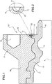
Figure 1 is an axial cross-sectional view of a first embodiment of a flanged bearing ring according to the invention; and -
Figure 2 is an enlarged view of a detail offigure 1 . - Before an embodiment of the invention is explained in detail, it is to be understood that the invention is not limited in its application to the details of construction and the arrangement of the components set forth in the following description or illustrated in the drawings. The invention is capable of other embodiments and of being practiced or being carried out in various ways. Also, it is to be understood that the phraseology and terminology used herein are for the purpose of description and should not be regarded as limiting. The use of "including", "comprising", and "forming", and variations thereof, is meant to encompass the items listed thereafter and equivalents thereof.
- Referring initially to
figure 1 , designated overall at 10 is a flanged bearing ring in accordance with an embodiment of the invention. Thering 10, in this example, is designed to be the outer, rotatable ring of a double-row angular contact ball bearing for vehicle applications, particularly for mounting to a vehicle wheel (not shown) to be rotationally supported relative to a stationary suspension standard (not shown) of the vehicle around a central axis of rotation x. Throughout the present description and the claims, terms and expressions indicating positions and directions such as "radial" and "axial" are understood as referring to the axis of rotation x of the bearing. Expressions such as "axially inner" and "axially outer" instead refer to a condition when mounted on a vehicle. - The
ring 10 comprises a radially inner insert orcore 15 of a generally tubular shape and a radiallyouter body 16 providing a radially outwardly extendingflange 17 at the outboard side of thecore 15. Theflange 17 provides a number ofbores 18 to allow connection to the vehicle wheel by means of stud bolts (not shown). - The
core 15 forms tworaceways outer body 16 is made of a second, lightweight material. A lightweight metal is preferred, such as aluminium, magnesium, or alloys thereof. Other suitable materials for the outer body may include, but not be limited to, carbon composites or reinforced polymers. In order to provide adequate structural support to theouter body 16, thesteel core 15 extends axially through the whole width of the outer body, from the inboard to the outboard side. Thetubular core 15 forms an axial tubular extension orspigot 19 at its outboard side, which facilitates centring of the vehicle wheel. Thespigot 19 protrudes axially from a radiallyouter surface 20 of theflange 17, facing an axially outer direction. - The
outer body 16 is formed around thecore 15 in a number of different ways, for example through a semi-solid casting process, or by sintering or casting, or die-casting. At the end of any of these processes, the lightweight material tightly copies the shape of the radially outboard surface ofcore 15, whereby the inner and outer bodies interlock with one another. The shape of the radially outboard surface of thecore 15 is so formed as to provide a series of grooves and ridges which extend in the circumferential direction and determine the formation of complementary ridges and grooves in the outer body when this is formed around the core. - Towards the axially inner end, the
core 15 forms aridge 13 which projects in a radially outer direction and extends in a circumferential direction. Theridge 13 serves as a shoulder to oppose relative axial displacement between theouter body 16 and thecore 15. Theridge 13 provides an axially outerradial surface 14 which is coplanar, or substantially coplanar, with the axiallyouter surface 20 offlange 17; thesurface 20 defines a precise reference surface against which the wheel or brake disc will rest. - At the axially outer end ring, at the outboard side where the
flange 17 is provided, the interface surface between the outer body and the core ends in agroove 21 formed partly by theouter body 16 and partly by theinner core 15. It is noted that the interface surface terminates in a position which is recessed with respect to the axially innerradial surfaces 20 of theflange ridge 13. - The
groove 21, which opens in an axially outer direction, may be obtained by turning in a terminal step of the manufacturing process of the ring, that is, after theouter body 16 has already been formed around thecore 15. As an alternative, thegroove 21 may be produced during the same manufacturing step in which the outer body is formed around the core, for example by means of an annular insert placed in the moulding cavity. - The
groove 21 serves as a seat to accommodate asealing ring 22 of polymeric material, preferably silicone resin, which covers continuously, along an entire circumference around the axis x, acircular separation line 23 between the steel of thecore 15 and the lightweight metal of theouter body 16, where the interface surface between the two materials meets the outboard side of thering 10. Thesealing ring 22 adheres to both the steel of thecore 15 and the lightweight metal of theouter body 16, and thereby hermetically seals, from the axially outer side, the interface between the two materials. - In the preferred embodiment, the
sealing ring 22 does not protrude beyond the flat surface defined byfaces groove 21. Due to this arrangement, the brake disc (not shown) does not contact thesealing ring 22, and therefore rests only against theflat surfaces 20 and possibly also surface 14. Otherwise, if the sealing ring protrudes axially beyond thesurfaces - Preferably, as shown in the enlargement of
Figure 2 , thegroove 21 is obtained to a greater extent in the outer body oflightweight metal 16, and to a lesser extent in theridge 13 of thecore 15. Due to this arrangement, a minor quantity of the material (steel) that provides the greatest contribution in terms of structural strength is removed, and therefore theridge 13 is not weaken to an appreciable extent. - Not necessarily the
groove 21 must have a rounded profile as shown. A rounded shape is preferable if one chooses to make a groove with thin dimensions, using a thin turning tool having a rounded head. - The material forming the
sealing ring 22 is applied in a liquid state, preferably by casting it in thegroove 21 after having oriented thering 10 in such a way that thesurface 20 is horizontal and facing upwards. In this way, the sealing material, once solidified, does not protrude beyond thesurfaces steel core 15 and theouter body 16 opens on the outboard side of the bearing.
Claims (9)
- A flanged bearing ring for a motor vehicle wheel, wherein the ring (10) comprises two different materials joined together as a single piece, the ring including:- a radially inner tubular or annular core (15) which forms an axially inner raceway (11) around a central axis of rotation (x), the core (15) providing a radially outer surface and being made of a first high toughness material;- a radially outer body (16) which is formed around said outer surface of the core (15), forms a radially outwardly extending flange (17) and is made of a second material being lighter than the first material;characterized in that at an axially outer end of the ring (10) where the flange (17) is provided, interface surfaces between the outer body (16) and the core (15) terminate in a groove (21) which is formed partly in the outer body (16) and partly in the core, and that seated in the groove (21) is a sealing ring (22) of polymeric material which is cast and covers continuously, along an entire circumference around the axis (x), a separation line (23) at the axially outer end of the interface surfaces between the core (15) and the outer body (16).
- A flanged ring according to claim 1, characterized in that the part of the groove (21) formed in the nucleus (15) is obtained in a ridge or shoulder (13) protruding in a radially outer direction and extending in a circumferential direction.
- A flanged ring according to claim 2, characterized in that the groove (21) is obtained to a greater extent in the outer body (16), and to a lesser extent in the ridge (13) of the core (15).
- A flanged ring according to claim 1, 2 or 3, characterized in that
the ridge (13) has an axially outer radial surface (14) coplanar or substantially flush with an axially outer, radial surface (20) of the flange (17),
the groove (21) separates the surfaces (14) and (20), and that
the sealing ring (22) only partially fills the groove (21) without protruding axially beyond the radial plane in which the surface (20) lies. - A flanged ring according to claim 4, characterized in that the sealing ring (22) is entirely axially recessed with respect to the plane in which the radial surface (20) of the flange (17) lies.
- A flanged ring according to any of the preceding claims, characterized in that the sealing ring (22) adheres to both the core (15) and the outer body (16) so as to hermetically seal, on the axially outer side of the ring (10), the interface between the core and the outer body.
- A flanged ring according to any of the preceding claims, characterized in that the sealing ring (22) is made of silicone resin.
- A flanged ring according to any of the preceding claims, characterized in that the groove (21) opens in an axially outer direction.
- A method of manufacturing a flanged bearing ring (10) for the wheel of a motor vehicle, the method comprising the steps of:a) providing an annular or tubular core (15) made of a first, high toughness material, the core forming at least one raceway (11) around a central axis (x) and having a radially outer surface;b) forming, around the outer surface of the core (15), a radially outer body (16) made of a second material lighter than the first material, the outer body (16) providing a flange (17) extending radially outwardly around the core (15), thereby obtaining a flanged ring (10) comprising two different materials joined together as a single piece;c) obtaining, simultaneously or subsequently to step b), a groove (21) at the axially outer end of the ring, at the side providing the flange (17), the groove (21) being formed in part by the outer body (16) and in part by the core (15);d) orienting the ring (10) so as to turn the groove (21) upwards;e) casting a polymeric liquid sealant in the groove (21), thereby obtaining a polymer sealing ring (22) which seals continuously, around the axis (x), a line of separation (23) at the axially outer end of the interface surfaces between the core (15) and outer body (16).
Applications Claiming Priority (1)
| Application Number | Priority Date | Filing Date | Title |
|---|---|---|---|
| IT000276A ITTO20110276A1 (en) | 2011-03-29 | 2011-03-29 | FLANGED BEARING RING FOR A WHEEL BEARING UNIT OF A MOTOR VEHICLE AND PROCEDURE FOR ITS MANUFACTURING |
Publications (2)
| Publication Number | Publication Date |
|---|---|
| EP2505378A1 true EP2505378A1 (en) | 2012-10-03 |
| EP2505378B1 EP2505378B1 (en) | 2014-11-05 |
Family
ID=43977508
Family Applications (1)
| Application Number | Title | Priority Date | Filing Date |
|---|---|---|---|
| EP12161681.7A Active EP2505378B1 (en) | 2011-03-29 | 2012-03-28 | A flanged bearing ring for the hub of a motor vehicle wheel and a method of manufacturing same |
Country Status (3)
| Country | Link |
|---|---|
| US (1) | US8944522B2 (en) |
| EP (1) | EP2505378B1 (en) |
| IT (1) | ITTO20110276A1 (en) |
Cited By (1)
| Publication number | Priority date | Publication date | Assignee | Title |
|---|---|---|---|---|
| CN111734745A (en) * | 2019-03-25 | 2020-10-02 | 斯凯孚公司 | Integrated bearing element and suspension upright module and method of manufacturing the same |
Families Citing this family (1)
| Publication number | Priority date | Publication date | Assignee | Title |
|---|---|---|---|---|
| US8763495B2 (en) * | 2011-02-11 | 2014-07-01 | General Electric Company | Torque tube, torque transfer apparatus and method |
Citations (4)
| Publication number | Priority date | Publication date | Assignee | Title |
|---|---|---|---|---|
| EP0297552A2 (en) * | 1987-07-01 | 1989-01-04 | Kawasaki Jukogyo Kabushiki Kaisha | Composite structures and methods of manufacturing the same |
| WO2008147284A1 (en) | 2007-06-01 | 2008-12-04 | Aktiebolaget Skf | A bearing component for a rolling bearing or for a sliding bearing |
| WO2010063299A1 (en) * | 2008-12-02 | 2010-06-10 | Ab Skf | Bearing unit |
| US20100331093A1 (en) * | 2007-09-12 | 2010-12-30 | Masahiro Ozawa | Bearing device for wheel, and axle module |
Family Cites Families (6)
| Publication number | Priority date | Publication date | Assignee | Title |
|---|---|---|---|---|
| NL6805109A (en) * | 1968-04-10 | 1969-10-14 | ||
| JPH027278Y2 (en) * | 1984-09-10 | 1990-02-21 | ||
| US6497515B1 (en) * | 1999-06-18 | 2002-12-24 | Ntn Corporation | Bearing apparatus for wheel |
| JP3942366B2 (en) * | 2000-12-26 | 2007-07-11 | Ntn株式会社 | Wheel bearing device and manufacturing method thereof |
| DE10314626A1 (en) * | 2002-04-11 | 2004-01-29 | Ntn Corp. | Bearing device for a drive wheel of a vehicle |
| US7461904B2 (en) * | 2005-06-17 | 2008-12-09 | Shimano Inc. | Bicycle hub sealing structure |
-
2011
- 2011-03-29 IT IT000276A patent/ITTO20110276A1/en unknown
-
2012
- 2012-03-22 US US13/426,690 patent/US8944522B2/en active Active
- 2012-03-28 EP EP12161681.7A patent/EP2505378B1/en active Active
Patent Citations (4)
| Publication number | Priority date | Publication date | Assignee | Title |
|---|---|---|---|---|
| EP0297552A2 (en) * | 1987-07-01 | 1989-01-04 | Kawasaki Jukogyo Kabushiki Kaisha | Composite structures and methods of manufacturing the same |
| WO2008147284A1 (en) | 2007-06-01 | 2008-12-04 | Aktiebolaget Skf | A bearing component for a rolling bearing or for a sliding bearing |
| US20100331093A1 (en) * | 2007-09-12 | 2010-12-30 | Masahiro Ozawa | Bearing device for wheel, and axle module |
| WO2010063299A1 (en) * | 2008-12-02 | 2010-06-10 | Ab Skf | Bearing unit |
Cited By (1)
| Publication number | Priority date | Publication date | Assignee | Title |
|---|---|---|---|---|
| CN111734745A (en) * | 2019-03-25 | 2020-10-02 | 斯凯孚公司 | Integrated bearing element and suspension upright module and method of manufacturing the same |
Also Published As
| Publication number | Publication date |
|---|---|
| EP2505378B1 (en) | 2014-11-05 |
| US20120248856A1 (en) | 2012-10-04 |
| US8944522B2 (en) | 2015-02-03 |
| ITTO20110276A1 (en) | 2012-09-30 |
Similar Documents
| Publication | Publication Date | Title |
|---|---|---|
| EP2558737B1 (en) | A flanged bearing ring for a motor vehicle wheel bearing unit | |
| EP2378143B1 (en) | A flanged bearing ring for a motor vehicle wheel bearing unit | |
| EP2373896B1 (en) | Bearing unit | |
| EP2754565B1 (en) | Lightweight hub unit with integrated bearing rings and processes for its manufacture | |
| EP2378142B1 (en) | A flanged bearing ring for a motor vehicle wheel bearing unit | |
| EP2505379B1 (en) | A flanged bearing ring for a bearing unit of a motor vehicle wheel | |
| EP2505383B1 (en) | A flanged bearing ring for the hub of a motor vehicle wheel | |
| EP2505382B1 (en) | A flanged bearing ring for the hub of a motor vehicle wheel | |
| EP2754564A1 (en) | Lightweight hub unit with integrated bearing rings and process for its manufacture | |
| EP2604445B1 (en) | A hub-bearing assembly for the wheel of a mothor vehicle | |
| EP2505380B1 (en) | A flanged bearing ring for the hub of a motor vehicle wheel | |
| EP2505378B1 (en) | A flanged bearing ring for the hub of a motor vehicle wheel and a method of manufacturing same | |
| EP2871067B1 (en) | Bearing-hub assembly with a light alloy hub | |
| EP2505381B1 (en) | A form-coupling arrangement in a bearing ring for a motor vehicle wheel |
Legal Events
| Date | Code | Title | Description |
|---|---|---|---|
| PUAI | Public reference made under article 153(3) epc to a published international application that has entered the european phase |
Free format text: ORIGINAL CODE: 0009012 |
|
| AK | Designated contracting states |
Kind code of ref document: A1 Designated state(s): AL AT BE BG CH CY CZ DE DK EE ES FI FR GB GR HR HU IE IS IT LI LT LU LV MC MK MT NL NO PL PT RO RS SE SI SK SM TR |
|
| AX | Request for extension of the european patent |
Extension state: BA ME |
|
| 17P | Request for examination filed |
Effective date: 20130328 |
|
| REG | Reference to a national code |
Ref country code: DE Ref legal event code: R079 Ref document number: 602012003624 Country of ref document: DE Free format text: PREVIOUS MAIN CLASS: B60B0027000000 Ipc: F16C0033620000 |
|
| GRAP | Despatch of communication of intention to grant a patent |
Free format text: ORIGINAL CODE: EPIDOSNIGR1 |
|
| GRAJ | Information related to disapproval of communication of intention to grant by the applicant or resumption of examination proceedings by the epo deleted |
Free format text: ORIGINAL CODE: EPIDOSDIGR1 |
|
| GRAP | Despatch of communication of intention to grant a patent |
Free format text: ORIGINAL CODE: EPIDOSNIGR1 |
|
| RIC1 | Information provided on ipc code assigned before grant |
Ipc: F16C 33/62 20060101AFI20130903BHEP Ipc: B60B 27/00 20060101ALI20130903BHEP Ipc: F16C 33/64 20060101ALI20130903BHEP Ipc: B22D 19/04 20060101ALI20130903BHEP |
|
| INTG | Intention to grant announced |
Effective date: 20130925 |
|
| INTC | Intention to grant announced (deleted) | ||
| GRAP | Despatch of communication of intention to grant a patent |
Free format text: ORIGINAL CODE: EPIDOSNIGR1 |
|
| INTG | Intention to grant announced |
Effective date: 20140708 |
|
| GRAS | Grant fee paid |
Free format text: ORIGINAL CODE: EPIDOSNIGR3 |
|
| GRAA | (expected) grant |
Free format text: ORIGINAL CODE: 0009210 |
|
| AK | Designated contracting states |
Kind code of ref document: B1 Designated state(s): AL AT BE BG CH CY CZ DE DK EE ES FI FR GB GR HR HU IE IS IT LI LT LU LV MC MK MT NL NO PL PT RO RS SE SI SK SM TR |
|
| REG | Reference to a national code |
Ref country code: GB Ref legal event code: FG4D |
|
| REG | Reference to a national code |
Ref country code: CH Ref legal event code: EP |
|
| REG | Reference to a national code |
Ref country code: AT Ref legal event code: REF Ref document number: 694808 Country of ref document: AT Kind code of ref document: T Effective date: 20141115 |
|
| REG | Reference to a national code |
Ref country code: IE Ref legal event code: FG4D |
|
| REG | Reference to a national code |
Ref country code: DE Ref legal event code: R096 Ref document number: 602012003624 Country of ref document: DE Effective date: 20141224 |
|
| REG | Reference to a national code |
Ref country code: SE Ref legal event code: TRGR |
|
| REG | Reference to a national code |
Ref country code: AT Ref legal event code: MK05 Ref document number: 694808 Country of ref document: AT Kind code of ref document: T Effective date: 20141105 |
|
| REG | Reference to a national code |
Ref country code: NL Ref legal event code: VDEP Effective date: 20141105 |
|
| REG | Reference to a national code |
Ref country code: LT Ref legal event code: MG4D |
|
| PG25 | Lapsed in a contracting state [announced via postgrant information from national office to epo] |
Ref country code: IS Free format text: LAPSE BECAUSE OF FAILURE TO SUBMIT A TRANSLATION OF THE DESCRIPTION OR TO PAY THE FEE WITHIN THE PRESCRIBED TIME-LIMIT Effective date: 20150305 Ref country code: NO Free format text: LAPSE BECAUSE OF FAILURE TO SUBMIT A TRANSLATION OF THE DESCRIPTION OR TO PAY THE FEE WITHIN THE PRESCRIBED TIME-LIMIT Effective date: 20150205 Ref country code: LT Free format text: LAPSE BECAUSE OF FAILURE TO SUBMIT A TRANSLATION OF THE DESCRIPTION OR TO PAY THE FEE WITHIN THE PRESCRIBED TIME-LIMIT Effective date: 20141105 Ref country code: NL Free format text: LAPSE BECAUSE OF FAILURE TO SUBMIT A TRANSLATION OF THE DESCRIPTION OR TO PAY THE FEE WITHIN THE PRESCRIBED TIME-LIMIT Effective date: 20141105 Ref country code: PT Free format text: LAPSE BECAUSE OF FAILURE TO SUBMIT A TRANSLATION OF THE DESCRIPTION OR TO PAY THE FEE WITHIN THE PRESCRIBED TIME-LIMIT Effective date: 20150305 Ref country code: FI Free format text: LAPSE BECAUSE OF FAILURE TO SUBMIT A TRANSLATION OF THE DESCRIPTION OR TO PAY THE FEE WITHIN THE PRESCRIBED TIME-LIMIT Effective date: 20141105 Ref country code: ES Free format text: LAPSE BECAUSE OF FAILURE TO SUBMIT A TRANSLATION OF THE DESCRIPTION OR TO PAY THE FEE WITHIN THE PRESCRIBED TIME-LIMIT Effective date: 20141105 |
|
| PG25 | Lapsed in a contracting state [announced via postgrant information from national office to epo] |
Ref country code: GR Free format text: LAPSE BECAUSE OF FAILURE TO SUBMIT A TRANSLATION OF THE DESCRIPTION OR TO PAY THE FEE WITHIN THE PRESCRIBED TIME-LIMIT Effective date: 20150206 Ref country code: RS Free format text: LAPSE BECAUSE OF FAILURE TO SUBMIT A TRANSLATION OF THE DESCRIPTION OR TO PAY THE FEE WITHIN THE PRESCRIBED TIME-LIMIT Effective date: 20141105 Ref country code: HR Free format text: LAPSE BECAUSE OF FAILURE TO SUBMIT A TRANSLATION OF THE DESCRIPTION OR TO PAY THE FEE WITHIN THE PRESCRIBED TIME-LIMIT Effective date: 20141105 Ref country code: LV Free format text: LAPSE BECAUSE OF FAILURE TO SUBMIT A TRANSLATION OF THE DESCRIPTION OR TO PAY THE FEE WITHIN THE PRESCRIBED TIME-LIMIT Effective date: 20141105 Ref country code: PL Free format text: LAPSE BECAUSE OF FAILURE TO SUBMIT A TRANSLATION OF THE DESCRIPTION OR TO PAY THE FEE WITHIN THE PRESCRIBED TIME-LIMIT Effective date: 20141105 Ref country code: AT Free format text: LAPSE BECAUSE OF FAILURE TO SUBMIT A TRANSLATION OF THE DESCRIPTION OR TO PAY THE FEE WITHIN THE PRESCRIBED TIME-LIMIT Effective date: 20141105 Ref country code: CY Free format text: LAPSE BECAUSE OF FAILURE TO SUBMIT A TRANSLATION OF THE DESCRIPTION OR TO PAY THE FEE WITHIN THE PRESCRIBED TIME-LIMIT Effective date: 20141105 |
|
| PG25 | Lapsed in a contracting state [announced via postgrant information from national office to epo] |
Ref country code: EE Free format text: LAPSE BECAUSE OF FAILURE TO SUBMIT A TRANSLATION OF THE DESCRIPTION OR TO PAY THE FEE WITHIN THE PRESCRIBED TIME-LIMIT Effective date: 20141105 Ref country code: CZ Free format text: LAPSE BECAUSE OF FAILURE TO SUBMIT A TRANSLATION OF THE DESCRIPTION OR TO PAY THE FEE WITHIN THE PRESCRIBED TIME-LIMIT Effective date: 20141105 Ref country code: DK Free format text: LAPSE BECAUSE OF FAILURE TO SUBMIT A TRANSLATION OF THE DESCRIPTION OR TO PAY THE FEE WITHIN THE PRESCRIBED TIME-LIMIT Effective date: 20141105 Ref country code: SK Free format text: LAPSE BECAUSE OF FAILURE TO SUBMIT A TRANSLATION OF THE DESCRIPTION OR TO PAY THE FEE WITHIN THE PRESCRIBED TIME-LIMIT Effective date: 20141105 |
|
| REG | Reference to a national code |
Ref country code: DE Ref legal event code: R097 Ref document number: 602012003624 Country of ref document: DE |
|
| PLBE | No opposition filed within time limit |
Free format text: ORIGINAL CODE: 0009261 |
|
| STAA | Information on the status of an ep patent application or granted ep patent |
Free format text: STATUS: NO OPPOSITION FILED WITHIN TIME LIMIT |
|
| 26N | No opposition filed |
Effective date: 20150806 |
|
| PG25 | Lapsed in a contracting state [announced via postgrant information from national office to epo] |
Ref country code: LU Free format text: LAPSE BECAUSE OF FAILURE TO SUBMIT A TRANSLATION OF THE DESCRIPTION OR TO PAY THE FEE WITHIN THE PRESCRIBED TIME-LIMIT Effective date: 20150328 Ref country code: MC Free format text: LAPSE BECAUSE OF FAILURE TO SUBMIT A TRANSLATION OF THE DESCRIPTION OR TO PAY THE FEE WITHIN THE PRESCRIBED TIME-LIMIT Effective date: 20141105 |
|
| REG | Reference to a national code |
Ref country code: CH Ref legal event code: PL |
|
| REG | Reference to a national code |
Ref country code: IE Ref legal event code: MM4A |
|
| PG25 | Lapsed in a contracting state [announced via postgrant information from national office to epo] |
Ref country code: LI Free format text: LAPSE BECAUSE OF NON-PAYMENT OF DUE FEES Effective date: 20150331 Ref country code: IE Free format text: LAPSE BECAUSE OF NON-PAYMENT OF DUE FEES Effective date: 20150328 Ref country code: CH Free format text: LAPSE BECAUSE OF NON-PAYMENT OF DUE FEES Effective date: 20150331 |
|
| PG25 | Lapsed in a contracting state [announced via postgrant information from national office to epo] |
Ref country code: SI Free format text: LAPSE BECAUSE OF FAILURE TO SUBMIT A TRANSLATION OF THE DESCRIPTION OR TO PAY THE FEE WITHIN THE PRESCRIBED TIME-LIMIT Effective date: 20141105 |
|
| REG | Reference to a national code |
Ref country code: FR Ref legal event code: PLFP Year of fee payment: 5 |
|
| PG25 | Lapsed in a contracting state [announced via postgrant information from national office to epo] |
Ref country code: RO Free format text: LAPSE BECAUSE OF FAILURE TO SUBMIT A TRANSLATION OF THE DESCRIPTION OR TO PAY THE FEE WITHIN THE PRESCRIBED TIME-LIMIT Effective date: 20141105 |
|
| PG25 | Lapsed in a contracting state [announced via postgrant information from national office to epo] |
Ref country code: MT Free format text: LAPSE BECAUSE OF FAILURE TO SUBMIT A TRANSLATION OF THE DESCRIPTION OR TO PAY THE FEE WITHIN THE PRESCRIBED TIME-LIMIT Effective date: 20141105 |
|
| PG25 | Lapsed in a contracting state [announced via postgrant information from national office to epo] |
Ref country code: IT Free format text: LAPSE BECAUSE OF NON-PAYMENT OF DUE FEES Effective date: 20160328 |
|
| REG | Reference to a national code |
Ref country code: FR Ref legal event code: PLFP Year of fee payment: 6 |
|
| PG25 | Lapsed in a contracting state [announced via postgrant information from national office to epo] |
Ref country code: HU Free format text: LAPSE BECAUSE OF FAILURE TO SUBMIT A TRANSLATION OF THE DESCRIPTION OR TO PAY THE FEE WITHIN THE PRESCRIBED TIME-LIMIT; INVALID AB INITIO Effective date: 20120328 Ref country code: BG Free format text: LAPSE BECAUSE OF FAILURE TO SUBMIT A TRANSLATION OF THE DESCRIPTION OR TO PAY THE FEE WITHIN THE PRESCRIBED TIME-LIMIT Effective date: 20141105 Ref country code: SM Free format text: LAPSE BECAUSE OF FAILURE TO SUBMIT A TRANSLATION OF THE DESCRIPTION OR TO PAY THE FEE WITHIN THE PRESCRIBED TIME-LIMIT Effective date: 20141105 |
|
| PG25 | Lapsed in a contracting state [announced via postgrant information from national office to epo] |
Ref country code: IT Free format text: LAPSE BECAUSE OF NON-PAYMENT OF DUE FEES Effective date: 20160328 Ref country code: TR Free format text: LAPSE BECAUSE OF FAILURE TO SUBMIT A TRANSLATION OF THE DESCRIPTION OR TO PAY THE FEE WITHIN THE PRESCRIBED TIME-LIMIT Effective date: 20141105 |
|
| PGRI | Patent reinstated in contracting state [announced from national office to epo] |
Ref country code: IT Effective date: 20170710 |
|
| PG25 | Lapsed in a contracting state [announced via postgrant information from national office to epo] |
Ref country code: BE Free format text: LAPSE BECAUSE OF FAILURE TO SUBMIT A TRANSLATION OF THE DESCRIPTION OR TO PAY THE FEE WITHIN THE PRESCRIBED TIME-LIMIT Effective date: 20141105 |
|
| REG | Reference to a national code |
Ref country code: FR Ref legal event code: PLFP Year of fee payment: 7 |
|
| PG25 | Lapsed in a contracting state [announced via postgrant information from national office to epo] |
Ref country code: MK Free format text: LAPSE BECAUSE OF FAILURE TO SUBMIT A TRANSLATION OF THE DESCRIPTION OR TO PAY THE FEE WITHIN THE PRESCRIBED TIME-LIMIT Effective date: 20141105 |
|
| PG25 | Lapsed in a contracting state [announced via postgrant information from national office to epo] |
Ref country code: AL Free format text: LAPSE BECAUSE OF FAILURE TO SUBMIT A TRANSLATION OF THE DESCRIPTION OR TO PAY THE FEE WITHIN THE PRESCRIBED TIME-LIMIT Effective date: 20141105 |
|
| PGFP | Annual fee paid to national office [announced via postgrant information from national office to epo] |
Ref country code: GB Payment date: 20190327 Year of fee payment: 8 |
|
| PGFP | Annual fee paid to national office [announced via postgrant information from national office to epo] |
Ref country code: SE Payment date: 20190328 Year of fee payment: 8 |
|
| PGFP | Annual fee paid to national office [announced via postgrant information from national office to epo] |
Ref country code: FR Payment date: 20190903 Year of fee payment: 8 |
|
| PG25 | Lapsed in a contracting state [announced via postgrant information from national office to epo] |
Ref country code: FR Free format text: LAPSE BECAUSE OF NON-PAYMENT OF DUE FEES Effective date: 20200331 Ref country code: SE Free format text: LAPSE BECAUSE OF NON-PAYMENT OF DUE FEES Effective date: 20200329 |
|
| GBPC | Gb: european patent ceased through non-payment of renewal fee |
Effective date: 20200328 |
|
| PG25 | Lapsed in a contracting state [announced via postgrant information from national office to epo] |
Ref country code: GB Free format text: LAPSE BECAUSE OF NON-PAYMENT OF DUE FEES Effective date: 20200328 |
|
| PGFP | Annual fee paid to national office [announced via postgrant information from national office to epo] |
Ref country code: IT Payment date: 20230321 Year of fee payment: 12 |
|
| P01 | Opt-out of the competence of the unified patent court (upc) registered |
Effective date: 20230513 |
|
| PGFP | Annual fee paid to national office [announced via postgrant information from national office to epo] |
Ref country code: DE Payment date: 20240328 Year of fee payment: 13 |