EP2505360B1 - Liquid ejecting apparatus - Google Patents
Liquid ejecting apparatus Download PDFInfo
- Publication number
- EP2505360B1 EP2505360B1 EP20120161248 EP12161248A EP2505360B1 EP 2505360 B1 EP2505360 B1 EP 2505360B1 EP 20120161248 EP20120161248 EP 20120161248 EP 12161248 A EP12161248 A EP 12161248A EP 2505360 B1 EP2505360 B1 EP 2505360B1
- Authority
- EP
- European Patent Office
- Prior art keywords
- liquid ejecting
- disposed
- wall
- unit
- liquid
- Prior art date
- Legal status (The legal status is an assumption and is not a legal conclusion. Google has not performed a legal analysis and makes no representation as to the accuracy of the status listed.)
- Active
Links
Images


Classifications
-
- B—PERFORMING OPERATIONS; TRANSPORTING
- B41—PRINTING; LINING MACHINES; TYPEWRITERS; STAMPS
- B41J—TYPEWRITERS; SELECTIVE PRINTING MECHANISMS, i.e. MECHANISMS PRINTING OTHERWISE THAN FROM A FORME; CORRECTION OF TYPOGRAPHICAL ERRORS
- B41J2/00—Typewriters or selective printing mechanisms characterised by the printing or marking process for which they are designed
- B41J2/005—Typewriters or selective printing mechanisms characterised by the printing or marking process for which they are designed characterised by bringing liquid or particles selectively into contact with a printing material
- B41J2/01—Ink jet
- B41J2/17—Ink jet characterised by ink handling
- B41J2/1714—Conditioning of the outside of ink supply systems, e.g. inkjet collector cleaning, ink mist removal
-
- B—PERFORMING OPERATIONS; TRANSPORTING
- B41—PRINTING; LINING MACHINES; TYPEWRITERS; STAMPS
- B41J—TYPEWRITERS; SELECTIVE PRINTING MECHANISMS, i.e. MECHANISMS PRINTING OTHERWISE THAN FROM A FORME; CORRECTION OF TYPOGRAPHICAL ERRORS
- B41J29/00—Details of, or accessories for, typewriters or selective printing mechanisms not otherwise provided for
- B41J29/02—Framework
-
- B—PERFORMING OPERATIONS; TRANSPORTING
- B41—PRINTING; LINING MACHINES; TYPEWRITERS; STAMPS
- B41J—TYPEWRITERS; SELECTIVE PRINTING MECHANISMS, i.e. MECHANISMS PRINTING OTHERWISE THAN FROM A FORME; CORRECTION OF TYPOGRAPHICAL ERRORS
- B41J29/00—Details of, or accessories for, typewriters or selective printing mechanisms not otherwise provided for
- B41J29/377—Cooling or ventilating arrangements
-
- B—PERFORMING OPERATIONS; TRANSPORTING
- B41—PRINTING; LINING MACHINES; TYPEWRITERS; STAMPS
- B41J—TYPEWRITERS; SELECTIVE PRINTING MECHANISMS, i.e. MECHANISMS PRINTING OTHERWISE THAN FROM A FORME; CORRECTION OF TYPOGRAPHICAL ERRORS
- B41J3/00—Typewriters or selective printing or marking mechanisms characterised by the purpose for which they are constructed
- B41J3/60—Typewriters or selective printing or marking mechanisms characterised by the purpose for which they are constructed for printing on both faces of the printing material
Definitions
- the present invention relates to liquid ejecting apparatuses that eject liquid onto an ejection target medium.
- an ink jet printer As an example of liquid ejecting apparatuses that eject liquid onto an ejection target medium, an ink jet printer will be described herein.
- recording is performed by ejecting (discharging) ink as an example of liquid onto a recording paper as an example of ejection target medium.
- ejecting disharging
- ink droplets have become smaller with the aim of further improving the recording quality of images, a problem has been raised due to fine droplets of ink.
- JP-A-2010-17935 discloses a recording apparatus having an air inlet port and an air outlet port on a side wall of a housing to form an inlet/outlet passage for cooling the electronic components, so that the mist of ink droplets generated by the ejected ink is discharged from the outlet port.
- most ink jet printers has an opening formed on the housing which constitutes the appearance of the apparatus and are configured such that an access target inside the apparatus can be accessed through the opening.
- an access target includes a sheet transportation path for releasing a paper jam, an ink cartridge or the like.
- the opening formed on the housing is often provided with an openable cover, which is usually in a closed state and constitutes the appearance of the apparatus.
- an access passage for accessing the access target inside the apparatus is disposed in an area in which a mist of ink is floating, the mist of ink may reach the opening through the access passage and smudge around the opening, thereby leading to an undesirable appearance of the apparatus.
- An advantage of some aspects of the invention is that a liquid ejecting apparatus capable of preventing the mist of ink from reaching the opening of the housing and also from floating inside the apparatus is provided.
- a liquid ejecting apparatus has the features of claim 1.
- Embodiments include a liquid ejecting unit that ejects a liquid onto an ejection target medium, and a protective wall that is disposed around an access passage for accessing an access target inside the apparatus from the outside the apparatus through an opening formed on a housing that constitutes an appearance of the apparatus, wherein the protective wall is disposed in an area in which a mist of the liquid ejected from the liquid ejecting unit is floating, and the protective wall is provided with a plurality of ribs formed on a surface thereof.
- the ribs can collect the floating mist, thereby reducing the amount of the mist reaching the opening. Further, as the ribs collect the floating mist, the amount of the mist floating inside the apparatus can be reduced.
- the ribs can prevent the user's hand from being in contact with a surface of the protective wall and from being smudged with the liquid as much as possible. Further, when the protective wall is formed by resin molding, the ribs can enhance the strength of the protective wall and prevent a molding problem such as warpage after molding.
- the access target according to the first example is a transportation path through which the ejection target medium is transported.
- the operational advantages of the first example of the invention can be obtained in the liquid ejecting apparatus in which the access target is the transportation path through which the ejection target medium is transported.
- the liquid ejecting apparatus includes a carriage that is movable in a scan direction of a liquid ejection head that constitutes the liquid ejecting unit, wherein the plurality of ribs extend in a direction that intersects with a moving direction of the carriage.
- the liquid ejecting apparatus since the liquid ejecting apparatus includes the carriage that is movable in the scan direction of the liquid ejection head that constitutes the liquid ejecting unit, the mist inside the apparatus tends to move in the moving direction of the carriage.
- the ribs since the ribs extend in the direction that intersects with the moving direction of the carriage, the ribs can effectively collect the mist floating inside the apparatus.
- the plurality of ribs according to any one of the first to third examples extend in a direction that intersects with a path direction from the liquid ejecting unit to the opening.
- the ribs extend in the direction that intersects with the path direction from the liquid ejecting unit to the opening, the ribs can effectively collect the mist flowing from the liquid ejecting unit to the opening.
- the protective wall according to any one of the first to fourth examples is formed by resin molding integrally with the housing that constitutes at least part of the appearance of the apparatus.
- the protective wall is formed by resin molding integrally with the housing, the protective wall can be made at a low cost.
- the liquid ejecting apparatus includes a carriage that is movable in a scan direction of the liquid ejection head that constitutes the liquid ejecting unit, wherein the protective wall is disposed above the moving area of the carriage, and a side wall of the housing and the protective wall are disposed such that an object whose heat is to be dissipated is placed therebetween.
- the protective wall is disposed above the moving area of the carriage, and the side wall of the housing and the protective wall are disposed such that the object whose heat is to be dissipated is placed therebetween, a volume of the space around the object whose heat is to be dissipated is decreased by the protective wall.
- the velocity of an air flow generated around the object whose heat is to be dissipated is increased, thereby effectively accelerating heat dissipation of the object whose heat is to be dissipated.
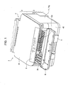
- Fig. 1 is a perspective view of a recording apparatus according to the invention that is, an ink jet printer 1 as an example of such a recording apparatus, as seen from the upper front side thereof;
- Fig. 2 is a perspective view of the ink jet printer 1 as seen from the front side thereof;
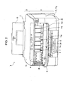
- Fig. 3 is a schematic side sectional view of the ink jet printer 1;
- Fig. 4 is a perspective view of a housing 11 as seen from the upper side thereof;
- Fig. 5 is a perspective view of the housing 11 as seen from the lower side thereof; and
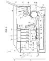
- Fig. 6 is a diagram which shows the relationship between a carriage 30 and an enclosing portion 11a.
- Reference numeral 2 in Figs. 1 and 2 denotes a recording unit that performs ink jet recording to a recording paper
- reference numeral 3 denotes a scanner unit mounted on the upper side of the recording unit 2. That is, the ink jet printer 1 is configured as a combined machine having an ink jet recording function and a scanner function.
- Reference numeral 5 denotes a sheet cassette that contains recording papers therein and is detachably mounted on the front side of the apparatus.
- Reference numeral 6 denotes an output port through which the recorded paper sheets are output, and reference numeral 7 ( Fig. 2 ) denotes an output sheet receiving tray that receives the output recording papers.
- Reference numeral 9 denotes an operation panel having a power button, operation buttons for various settings of printing or execution of recording, and a display that indicates the settings of printing or a preview of an image to be printed.
- reference numeral 10 denotes a cover that openably covers a platen (not shown) of the scanner unit 3 on the top of the apparatus.
- Reference numeral 11 denotes at least part of a housing that constitutes the appearance of the apparatus, more specifically, a portion of the housing that constitutes both side walls of the appearance of the apparatus. Further, the housing that constitutes the appearance of the ink jet printer 1 further includes a plurality of members, such as a front panel 49.
- Reference numeral 8 denotes a front cover that is configured to be openable. Figs. 1 and 2 show the front cover 8 is in an open state. When the front cover 8 is open, a paper jam releasing opening 2a and an ink cartridge storing unit 2b, both of which are formed on the housing that constitutes the appearance of the apparatus of the ink jet printer 1, are exposed to the outside.
- a user can insert his/her hand through the paper jam releasing opening 2a and access a portion of a sheet transportation path downstream of a transportation driving roller 24 and a transportation driven roller 25, which are described later, and remove the jammed paper sheet.
- the ink cartridge storing unit 2b can store a plurality of ink cartridges (not shown) therein and, when the front cover 8 is open, the ink cartridge can be replaced with new one.
- FIG. 3 is a schematic view of the configuration of the recording unit 2, in which not all the elements are shown, but only the elements that are necessary for explanation are illustrated.
- the recording unit 2 has two paper feeding paths, one of which is a paper feeding path from the sheet cassette 5 that is disposed in the lower area of the apparatus, while the other is a paper feeding path from a sheet feeding unit 4 that is disposed in the back area (on the right side in Fig. 3 ) of the apparatus. Further, the dashed line P1 indicates a path along which paper sheets are fed from the sheet cassette 5, while the dashed line P2 indicates a path along which paper sheets are fed from the sheet feeding unit 4.
- Reference numeral 18 denotes a feeding roller that is disposed at a position opposite the sheet cassette 5.
- the feeding roller 18 is movable toward and away from the sheet cassette 5 as shown in the solid line and the imaginary line (reference numeral 18') and rotates while being in contact with the uppermost sheet in the sheet cassette 5 so as to feed the uppermost sheet to the downstream area.
- the sheet is turned to be reversed around a large diameter reversing roller 20, and then sent to the transportation driving roller 24 and the transportation driven roller 25, which constitute a transportation unit.
- reference numeral 21 denotes a separation roller that cooperates with the reversing roller 20 to nip the paper sheet therebetween in order to separate the paper sheet to be fed.
- reference numerals 13 and 14 are support members that support the paper sheet to be set in an angled position.
- the support member 14 pivotally moves about a pivot shaft that is provided at the upper position of the support member 14, which is not shown, so that the uppermost sheet of the paper sheets supported thereon is brought into pressing contact with the feeding roller 15.
- the feeding roller 15 rotates so as to feed the paper sheet that is in pressing contact therewith to the downstream area.
- reference numeral 16 denotes a separation roller that cooperates with the feeding roller 15 to nip the paper sheet therebetween in order to separate the paper sheet to be fed.
- the transportation driving roller 24 and the transportation driven roller 25 constitute a pair of rollers that feeds the paper sheet to the downstream area in an accurate manner. Further, an ink jet recording head 31 as a liquid ejecting unit and a guiding member 28 that guides the paper sheet to the downstream area are disposed so as to oppose each other at positions downstream of the pair of rollers.
- the recording head 31 is disposed on the underside of the carriage 30 that is movable in a reciprocating motion in a direction perpendicular to a sheet transportation direction (a direction from the front to the back surface of the drawing sheet of Fig. 3 : hereinafter, referred to as "main scan direction" as appropriate) so that recording is performed by ejecting ink onto the paper sheet that is supported on the guiding member 28 while moving in the main scan direction.
- Reference numeral 33 denotes a driven roller that is disposed at a position downstream of the recording head 31 so as to prevent uplift of the paper sheet.
- Reference numeral 34 is an output driving roller that rotates so as to output the paper sheet, and reference numeral 35 is an output driven roller that cooperates with the output driving roller 34 to nip the paper sheet therebetween. After recording is performed on the paper sheet, the sheet is fed toward the output sheet receiving tray 7 by the above-mentioned pairs of rollers.
- the ink jet printer 1 is configured such that recording on the back surface (second surface) of the paper sheet is possible when the sheet is fed backward and turned over around the reversing roller 20, instead of being fed toward the output sheet receiving tray 7, after printing on the front surface (first surface) of the paper sheet is performed.
- the housing 11 includes a ceiling 11j, a right side wall 11g and a left side wall 11h that are disposed on each side of the ceiling 11j so as to generally form a substantially U-shape.
- An enclosing portion 11a that is integrally formed of a resin material is disposed inside of the U-shaped walls.
- the enclosing portion 11a is composed of a right side wall 11b, a left side wall 11c, and a back wall 11d.
- Figs. 3 and 6 show the positional relationship between the enclosing portion 11a and the carriage 30, such that the enclosing portion 11a is located above the moving area of the carriage 30.
- the right side wall 11b, the left side wall 11c and the back wall 11d are formed to extend downwardly from a recessed area 11f ( Figs. 3 and 4 ) that is formed on the ceiling 11j to positions as close as possible to the moving area of the carriage 30 (in order to assume an elongated shape) while preventing the forming accuracy from being lowered.
- the right side wall 11b, the left side wall 11c, and the back wall 11d that constitute the enclosing portion 11a serve as protective walls that protect the user's hand from the components inside the apparatus when the user inserts his/her hand into the apparatus through the paper jam releasing opening 2a during releasing of paper jam. That is, there is a risk that the user's hand may touch the sharp edges of the components inside the apparatus when the user inserts his/her hand into the apparatus to release the paper jam.
- the right side wall 11b, the left side wall 11c, and the back wall 11d being disposed in an access passage (for example, as indicated by reference numeral k in Fig. 3 ) for accessing an access target inside the apparatus (in this embodiment, the sheet transportation path), the user's hand can be protected from the sharp edges of the components inside the apparatus.
- the enclosing portion 11a is disposed above the moving area of the carriage 30, the enclosing portion 11a is located in an area in which a mist of ink ejected from the recording head 31 is floating.
- the mist of ink (indicated by reference numeral m in Fig. 3 ) may reach the paper jam releasing opening 2a through the access passage k, which is provided for accessing the sheet transportation path, and smudge around the paper jam releasing opening 2a, thereby leading to an undesirable appearance.
- each protective wall of the right side wall 11b, the left side wall 11c, and the back wall 11d is provided with a plurality of projections, that is, ribs 11e, that are formed on the surface thereof.
- a plurality of ribs lie can collect the floating mist of ink and reduce the amount of mist that reaches the paper jam releasing opening 2a.
- the amount of mist floating inside the apparatus also can be reduced as the ribs 11e collect the mist of ink.
- the ribs 11e can prevent the user's hand from being in contact with a surface of the protective wall and from being smudged with ink. Further, since each protective wall in this embodiment is formed by resin molding, the ribs 11e can enhance the strength of each protective wall and prevent a molding problem such as warpage after molding.
- the ribs 11e extend in a direction that intersects with a passage extending from the recording head 31 to the paper jam releasing opening 2a ( Fig. 3 ), the ribs 11e can effectively collect the mist of ink flowing toward the paper jam releasing opening 2a. Moreover, since the ribs 11e extend in a direction that intersects with a moving direction of the carriage 30 (left-right direction in Fig. 6 ), the ribs 11e can effectively collect the mist of ink that moves in accordance with the movement of the carriage 30.
- a circuit board 37 having electric components mounted thereon and a heat sink 38 that dissipates heat from the circuit board 37 are disposed between the right side wall 11g of the housing 11 and the right side wall 11b of the enclosing portion 11a as shown in Fig. 6 .
- the enclosing portion 11a can accelerate heat dissipation of the heat sink 38 as an example of an object whose heat is to be dissipated.
- reference numeral 11k denotes a vent formed on the right side wall 11g.
- the right side wall 11b, the left side wall 11c and the back wall 11d that serve as protective walls (enclosing portion 11a) have been described as being provided with respect to the access passage for accessing the sheet transportation path, which is the access target inside the apparatus.
- the access target may be the ink cartridges (not shown) contained in the ink cartridge storing unit 2b
- the right side wall 11b, the left side wall 11c and the back wall 11d may be provided with respect to the access passage for accessing the ink cartridges.
Landscapes
- Ink Jet (AREA)
- Accessory Devices And Overall Control Thereof (AREA)
Description
- The present invention relates to liquid ejecting apparatuses that eject liquid onto an ejection target medium.
- As an example of liquid ejecting apparatuses that eject liquid onto an ejection target medium, an ink jet printer will be described herein. In an ink jet printer, recording is performed by ejecting (discharging) ink as an example of liquid onto a recording paper as an example of ejection target medium. In recent years, as the size of ink droplets have become smaller with the aim of further improving the recording quality of images, a problem has been raised due to fine droplets of ink.
- That is, the ejected ink droplets float as a mist, which may damage components in the apparatus, thereby affecting the recording quality or operation of the apparatus. In an attempt to overcome such a problem,
JP-A-2010-17935 - Moreover, most ink jet printers has an opening formed on the housing which constitutes the appearance of the apparatus and are configured such that an access target inside the apparatus can be accessed through the opening. Such an access target includes a sheet transportation path for releasing a paper jam, an ink cartridge or the like.
- The opening formed on the housing is often provided with an openable cover, which is usually in a closed state and constitutes the appearance of the apparatus. However, in the case where an access passage for accessing the access target inside the apparatus is disposed in an area in which a mist of ink is floating, the mist of ink may reach the opening through the access passage and smudge around the opening, thereby leading to an undesirable appearance of the apparatus.
-
US 5,552,812 discloses features falling under the preamble of claim 1.JP 2008/260154 US 4,800,398 , andUS 2003/0076399 A1 are further prior art. - An advantage of some aspects of the invention is that a liquid ejecting apparatus capable of preventing the mist of ink from reaching the opening of the housing and also from floating inside the apparatus is provided.
- In a first example of the invention, a liquid ejecting apparatus has the features of claim 1. Embodiments include a liquid ejecting unit that ejects a liquid onto an ejection target medium, and a protective wall that is disposed around an access passage for accessing an access target inside the apparatus from the outside the apparatus through an opening formed on a housing that constitutes an appearance of the apparatus, wherein the protective wall is disposed in an area in which a mist of the liquid ejected from the liquid ejecting unit is floating, and the protective wall is provided with a plurality of ribs formed on a surface thereof.
- Accordingly, since the plurality of ribs are formed on the surface of the protective wall that is disposed around the access passage for accessing the access target inside the apparatus through the opening formed on the apparatus, the ribs can collect the floating mist, thereby reducing the amount of the mist reaching the opening. Further, as the ribs collect the floating mist, the amount of the mist floating inside the apparatus can be reduced.
- In addition to that, when a user accesses the access target inside the apparatus, the ribs can prevent the user's hand from being in contact with a surface of the protective wall and from being smudged with the liquid as much as possible. Further, when the protective wall is formed by resin molding, the ribs can enhance the strength of the protective wall and prevent a molding problem such as warpage after molding.
- In a second example of the invention, the access target according to the first example is a transportation path through which the ejection target medium is transported.
- Accordingly, the operational advantages of the first example of the invention can be obtained in the liquid ejecting apparatus in which the access target is the transportation path through which the ejection target medium is transported.
- In a third example of the invention, the liquid ejecting apparatus according to any one of the first and second examples includes a carriage that is movable in a scan direction of a liquid ejection head that constitutes the liquid ejecting unit, wherein the plurality of ribs extend in a direction that intersects with a moving direction of the carriage.
- Accordingly, since the liquid ejecting apparatus includes the carriage that is movable in the scan direction of the liquid ejection head that constitutes the liquid ejecting unit, the mist inside the apparatus tends to move in the moving direction of the carriage. In this example, since the ribs extend in the direction that intersects with the moving direction of the carriage, the ribs can effectively collect the mist floating inside the apparatus.
- In a fourth example of the invention, the plurality of ribs according to any one of the first to third examples extend in a direction that intersects with a path direction from the liquid ejecting unit to the opening.
- Accordingly, since the ribs extend in the direction that intersects with the path direction from the liquid ejecting unit to the opening, the ribs can effectively collect the mist flowing from the liquid ejecting unit to the opening.
- In a fifth example of the invention, the protective wall according to any one of the first to fourth examples is formed by resin molding integrally with the housing that constitutes at least part of the appearance of the apparatus.
- Accordingly, since the protective wall is formed by resin molding integrally with the housing, the protective wall can be made at a low cost.
- In a sixth example of the invention, the liquid ejecting apparatus according to the third example includes a carriage that is movable in a scan direction of the liquid ejection head that constitutes the liquid ejecting unit, wherein the protective wall is disposed above the moving area of the carriage, and a side wall of the housing and the protective wall are disposed such that an object whose heat is to be dissipated is placed therebetween.
- Accordingly, since the protective wall is disposed above the moving area of the carriage, and the side wall of the housing and the protective wall are disposed such that the object whose heat is to be dissipated is placed therebetween, a volume of the space around the object whose heat is to be dissipated is decreased by the protective wall. As a result, when the carriage moves, the velocity of an air flow generated around the object whose heat is to be dissipated is increased, thereby effectively accelerating heat dissipation of the object whose heat is to be dissipated.
- The invention will be described with reference to the accompanying drawings, wherein like numbers reference like elements.
-
Fig. 1 is a perspective view of an ink jet printer according to the invention as seen from the upper front side thereof. -
Fig. 2 is a perspective view of the ink jet printer according to the invention as seen from the front side thereof. -
Fig. 3 is a schematic side sectional view of the ink jet printer according to the invention. -
Fig. 4 is a perspective view of a housing as seen from the upper side thereof. -
Fig. 5 is a perspective view of the housing as seen from the lower side thereof. -
Fig. 6 is a diagram which shows the relationship between a carriage and an enclosing portion. - Although one embodiment of the invention will be described with reference to the accompanying drawings, it should be understood that the embodiment described herein is not exclusive and various modifications are deemed to be within the scope of the invention as defined by the appended claims.
-
Fig. 1 is a perspective view of a recording apparatus according to the invention that is, an ink jet printer 1 as an example of such a recording apparatus, as seen from the upper front side thereof;Fig. 2 is a perspective view of the ink jet printer 1 as seen from the front side thereof;Fig. 3 is a schematic side sectional view of the ink jet printer 1;Fig. 4 is a perspective view of ahousing 11 as seen from the upper side thereof;Fig. 5 is a perspective view of thehousing 11 as seen from the lower side thereof; andFig. 6 is a diagram which shows the relationship between acarriage 30 and an enclosingportion 11a. - First, an overall configuration of the ink jet printer 1 will be described below.
Reference numeral 2 inFigs. 1 and2 denotes a recording unit that performs ink jet recording to a recording paper, andreference numeral 3 denotes a scanner unit mounted on the upper side of therecording unit 2. That is, the ink jet printer 1 is configured as a combined machine having an ink jet recording function and a scanner function. -
Reference numeral 5 denotes a sheet cassette that contains recording papers therein and is detachably mounted on the front side of the apparatus. Reference numeral 6 (Fig. 2 ) denotes an output port through which the recorded paper sheets are output, and reference numeral 7 (Fig. 2 ) denotes an output sheet receiving tray that receives the output recording papers. -
Reference numeral 9 denotes an operation panel having a power button, operation buttons for various settings of printing or execution of recording, and a display that indicates the settings of printing or a preview of an image to be printed. Further,reference numeral 10 denotes a cover that openably covers a platen (not shown) of thescanner unit 3 on the top of the apparatus.Reference numeral 11 denotes at least part of a housing that constitutes the appearance of the apparatus, more specifically, a portion of the housing that constitutes both side walls of the appearance of the apparatus. Further, the housing that constitutes the appearance of the ink jet printer 1 further includes a plurality of members, such as a front panel 49. -
Reference numeral 8 denotes a front cover that is configured to be openable.Figs. 1 and2 show thefront cover 8 is in an open state. When thefront cover 8 is open, a paper jam releasing opening 2a and an inkcartridge storing unit 2b, both of which are formed on the housing that constitutes the appearance of the apparatus of the ink jet printer 1, are exposed to the outside. - A user can insert his/her hand through the paper jam releasing opening 2a and access a portion of a sheet transportation path downstream of a
transportation driving roller 24 and a transportation drivenroller 25, which are described later, and remove the jammed paper sheet. Further, the inkcartridge storing unit 2b can store a plurality of ink cartridges (not shown) therein and, when thefront cover 8 is open, the ink cartridge can be replaced with new one. - Next, referring to
Fig. 3 , the sheet transportation path in therecording unit 2 will be described.Fig. 3 is a schematic view of the configuration of therecording unit 2, in which not all the elements are shown, but only the elements that are necessary for explanation are illustrated. - The
recording unit 2 has two paper feeding paths, one of which is a paper feeding path from thesheet cassette 5 that is disposed in the lower area of the apparatus, while the other is a paper feeding path from asheet feeding unit 4 that is disposed in the back area (on the right side inFig. 3 ) of the apparatus. Further, the dashed line P1 indicates a path along which paper sheets are fed from thesheet cassette 5, while the dashed line P2 indicates a path along which paper sheets are fed from thesheet feeding unit 4. -
Reference numeral 18 denotes a feeding roller that is disposed at a position opposite thesheet cassette 5. The feedingroller 18 is movable toward and away from thesheet cassette 5 as shown in the solid line and the imaginary line (reference numeral 18') and rotates while being in contact with the uppermost sheet in thesheet cassette 5 so as to feed the uppermost sheet to the downstream area. The sheet is turned to be reversed around a largediameter reversing roller 20, and then sent to thetransportation driving roller 24 and the transportation drivenroller 25, which constitute a transportation unit. Further,reference numeral 21 denotes a separation roller that cooperates with the reversingroller 20 to nip the paper sheet therebetween in order to separate the paper sheet to be fed. - In the
sheet feeding unit 4 that is disposed in the back area of the apparatus,reference numerals support member 14 pivotally moves about a pivot shaft that is provided at the upper position of thesupport member 14, which is not shown, so that the uppermost sheet of the paper sheets supported thereon is brought into pressing contact with the feedingroller 15. The feedingroller 15 rotates so as to feed the paper sheet that is in pressing contact therewith to the downstream area. Further,reference numeral 16 denotes a separation roller that cooperates with the feedingroller 15 to nip the paper sheet therebetween in order to separate the paper sheet to be fed. - The
transportation driving roller 24 and the transportation drivenroller 25 constitute a pair of rollers that feeds the paper sheet to the downstream area in an accurate manner. Further, an inkjet recording head 31 as a liquid ejecting unit and a guidingmember 28 that guides the paper sheet to the downstream area are disposed so as to oppose each other at positions downstream of the pair of rollers. - The
recording head 31 is disposed on the underside of thecarriage 30 that is movable in a reciprocating motion in a direction perpendicular to a sheet transportation direction (a direction from the front to the back surface of the drawing sheet ofFig. 3 : hereinafter, referred to as "main scan direction" as appropriate) so that recording is performed by ejecting ink onto the paper sheet that is supported on the guidingmember 28 while moving in the main scan direction. -
Reference numeral 33 denotes a driven roller that is disposed at a position downstream of therecording head 31 so as to prevent uplift of the paper sheet.Reference numeral 34 is an output driving roller that rotates so as to output the paper sheet, andreference numeral 35 is an output driven roller that cooperates with theoutput driving roller 34 to nip the paper sheet therebetween. After recording is performed on the paper sheet, the sheet is fed toward the outputsheet receiving tray 7 by the above-mentioned pairs of rollers. - Moreover, the ink jet printer 1 is configured such that recording on the back surface (second surface) of the paper sheet is possible when the sheet is fed backward and turned over around the reversing
roller 20, instead of being fed toward the outputsheet receiving tray 7, after printing on the front surface (first surface) of the paper sheet is performed. - The schematic configuration of the ink jet printer 1 has been described above. The description below explains the enclosing
portion 11a that is formed in thehousing 11. As shown inFigs. 3 to 5 , thehousing 11 includes aceiling 11j, aright side wall 11g and aleft side wall 11h that are disposed on each side of theceiling 11j so as to generally form a substantially U-shape. An enclosingportion 11a that is integrally formed of a resin material is disposed inside of the U-shaped walls. - The enclosing
portion 11a is composed of aright side wall 11b, aleft side wall 11c, and aback wall 11d.Figs. 3 and6 show the positional relationship between the enclosingportion 11a and thecarriage 30, such that the enclosingportion 11a is located above the moving area of thecarriage 30. Theright side wall 11b, theleft side wall 11c and theback wall 11d are formed to extend downwardly from a recessedarea 11f (Figs. 3 and4 ) that is formed on theceiling 11j to positions as close as possible to the moving area of the carriage 30 (in order to assume an elongated shape) while preventing the forming accuracy from being lowered. - The
right side wall 11b, theleft side wall 11c, and theback wall 11d that constitute the enclosingportion 11a serve as protective walls that protect the user's hand from the components inside the apparatus when the user inserts his/her hand into the apparatus through the paperjam releasing opening 2a during releasing of paper jam. That is, there is a risk that the user's hand may touch the sharp edges of the components inside the apparatus when the user inserts his/her hand into the apparatus to release the paper jam. - However, with the
right side wall 11b, theleft side wall 11c, and theback wall 11d being disposed in an access passage (for example, as indicated by reference numeral k inFig. 3 ) for accessing an access target inside the apparatus (in this embodiment, the sheet transportation path), the user's hand can be protected from the sharp edges of the components inside the apparatus. - Further, since the enclosing
portion 11a is disposed above the moving area of thecarriage 30, the enclosingportion 11a is located in an area in which a mist of ink ejected from therecording head 31 is floating. As a result, the mist of ink (indicated by reference numeral m inFig. 3 ) may reach the paperjam releasing opening 2a through the access passage k, which is provided for accessing the sheet transportation path, and smudge around the paperjam releasing opening 2a, thereby leading to an undesirable appearance. - However, each protective wall of the
right side wall 11b, theleft side wall 11c, and theback wall 11d, is provided with a plurality of projections, that is,ribs 11e, that are formed on the surface thereof. A plurality of ribs lie can collect the floating mist of ink and reduce the amount of mist that reaches the paperjam releasing opening 2a. Moreover, the amount of mist floating inside the apparatus also can be reduced as theribs 11e collect the mist of ink. - In addition to that, when the user accesses the sheet transportation path to release the paper jam, the
ribs 11e can prevent the user's hand from being in contact with a surface of the protective wall and from being smudged with ink. Further, since each protective wall in this embodiment is formed by resin molding, theribs 11e can enhance the strength of each protective wall and prevent a molding problem such as warpage after molding. - In this embodiment, since the
ribs 11e extend in a direction that intersects with a passage extending from therecording head 31 to the paperjam releasing opening 2a (Fig. 3 ), theribs 11e can effectively collect the mist of ink flowing toward the paperjam releasing opening 2a. Moreover, since theribs 11e extend in a direction that intersects with a moving direction of the carriage 30 (left-right direction inFig. 6 ), theribs 11e can effectively collect the mist of ink that moves in accordance with the movement of thecarriage 30. - Further, in this embodiment, a
circuit board 37 having electric components mounted thereon and aheat sink 38 that dissipates heat from thecircuit board 37 are disposed between theright side wall 11g of thehousing 11 and theright side wall 11b of the enclosingportion 11a as shown inFig. 6 . - When the
carriage 30 moves toward theright side wall 11g, the air in the space A around theheat sink 38 is pressed, thereby generating an air flow in a direction as indicated by the arrow inFig. 6 to accelerate cooling of theheat sink 38. At this time, as theright side wall 11b of the enclosingportion 11a moves to decrease the volume of the space A, the velocity of the air flow can be increased. Further, when thecarriage 30 moves away from theright side wall 11g, the pressure in the space A becomes a negative pressure, thereby generating an air flow in a direction opposite to the arrow inFig. 6 to accelerate cooling of theheat sink 38. Accordingly, the enclosingportion 11a can accelerate heat dissipation of theheat sink 38 as an example of an object whose heat is to be dissipated. In addition,reference numeral 11k denotes a vent formed on theright side wall 11g. - The above-mentioned embodiment is described for exemplary purposes only and it is needless to say that the invention is not limited to the above-mentioned embodiment. For example, in this embodiment, the
right side wall 11b, theleft side wall 11c and theback wall 11d that serve as protective walls (enclosingportion 11a) have been described as being provided with respect to the access passage for accessing the sheet transportation path, which is the access target inside the apparatus. However, the access target may be the ink cartridges (not shown) contained in the inkcartridge storing unit 2b, and theright side wall 11b, theleft side wall 11c and theback wall 11d may be provided with respect to the access passage for accessing the ink cartridges.
Claims (9)
- A liquid ejecting apparatus (1) comprising:a liquid ejecting unit (31) that is arranged to eject a liquid onto an ejection target medium;a housing that houses the liquid ejecting unit;
characterized bya wall (11d) that is disposed at a position above the liquid ejecting unit and which extends from the housing in the vertical direction so that the liquid can adhere thereto, the wall being disposed around an access passage for accessing an access target inside the apparatus from the outside of the apparatus through an opening formed on the housing of the apparatus, wherein the wall is disposed in an area in which mist of the liquid ejected from the liquid ejecting unit is floating, and the wall is provided with a plurality of ribs formed on the surface thereof. - The liquid ejecting apparatus (1) according to Claim 1, further comprising an enclosing portion that is composed of at least three faces (11d,b,c) including the wall (11d) so as to form a space therein, wherein the liquid ejecting unit (31) is disposed in the space, and the enclosing portion communicates with the space.
- The liquid ejecting apparatus (1) according to Claim 2, further comprising:an opening (k) that communicates the space in which the liquid ejecting unit (31) is disposed and the outside of the housing; anda cover (8) that openably covers the opening, wherein the enclosing portion includes the wall and the cover (8).
- The liquid ejecting apparatus (1) according to one of the preceding Claims, further comprising a carriage (30) that has the liquid ejecting unit (31) mounted thereon and is configured to scan, wherein the wall is disposed in a scanning area of the carriage (30) and above the moving area of the carriage.
- The liquid ejecting apparatus (1) according to Claim 2, 3 or 4, wherein the enclosing portion has a plurality of ribs formed on the inner side thereof.
- The liquid ejecting apparatus (1) according to any one of the preceding claims, wherein the enclosing portion has a plurality of ribs formed on the outer side thereof.
- The liquid ejecting apparatus (1) according to any one of the preceding claims, wherein an ejection target medium feeding unit (20) is disposed in the space outside the enclosing portion.
- The liquid ejecting apparatus (1) according to Claim 3 or any preceding claim when dependent on claim 3, further comprising a storing unit (2b) that is disposed adjacent to the opening and contains a liquid storing unit that is arranged to store a liquid, wherein part of the wall separates the storing unit and the opening.
- The liquid ejecting apparatus (1) according to any one of the preceding claims, comprising an ejection target medium cassette (5) being arranged to contain ejection target media therein, the ejection target medium cassette being provided in a bottom part of the apparatus (1) and lower than the liquid ejecting unit (31).
Applications Claiming Priority (1)
| Application Number | Priority Date | Filing Date | Title |
|---|---|---|---|
| JP2011069528A JP5810578B2 (en) | 2011-03-28 | 2011-03-28 | Liquid ejector |
Publications (2)
| Publication Number | Publication Date |
|---|---|
| EP2505360A1 EP2505360A1 (en) | 2012-10-03 |
| EP2505360B1 true EP2505360B1 (en) | 2014-04-16 |
Family
ID=45939175
Family Applications (1)
| Application Number | Title | Priority Date | Filing Date |
|---|---|---|---|
| EP20120161248 Active EP2505360B1 (en) | 2011-03-28 | 2012-03-26 | Liquid ejecting apparatus |
Country Status (4)
| Country | Link |
|---|---|
| US (1) | US9132643B2 (en) |
| EP (1) | EP2505360B1 (en) |
| JP (1) | JP5810578B2 (en) |
| CN (1) | CN102717609B (en) |
Families Citing this family (4)
| Publication number | Priority date | Publication date | Assignee | Title |
|---|---|---|---|---|
| JP5998471B2 (en) * | 2011-12-20 | 2016-09-28 | セイコーエプソン株式会社 | adapter |
| JP6988163B2 (en) * | 2017-05-19 | 2022-01-05 | セイコーエプソン株式会社 | Carriage and liquid discharge device |
| JP7404992B2 (en) * | 2020-04-23 | 2023-12-26 | セイコーエプソン株式会社 | recording device |
| JP2022050825A (en) * | 2020-09-18 | 2022-03-31 | 株式会社Screenホールディングス | Printer and print method |
Family Cites Families (14)
| Publication number | Priority date | Publication date | Assignee | Title |
|---|---|---|---|---|
| JPS63125346A (en) * | 1986-11-14 | 1988-05-28 | Ricoh Co Ltd | Head module of ink jet printing apparatus |
| DE3750466T2 (en) * | 1986-12-10 | 1995-02-09 | Canon Kk | Recorder. |
| JP3376216B2 (en) * | 1995-07-18 | 2003-02-10 | キヤノン株式会社 | Image forming device |
| JP2001113772A (en) | 1999-08-11 | 2001-04-24 | Canon Inc | Image-forming apparatus |
| US6848850B2 (en) * | 2001-10-24 | 2005-02-01 | Matsushita Electric Industrial Co., Ltd. | Recording apparatus |
| JP2004117589A (en) | 2002-09-24 | 2004-04-15 | Canon Inc | Image forming apparatus |
| JP2004142192A (en) | 2002-10-23 | 2004-05-20 | Seiko Epson Corp | Recorder |
| JP2006240139A (en) * | 2005-03-04 | 2006-09-14 | Canon Inc | Inkjet recorder, and inkjet recording method |
| JP2007038469A (en) * | 2005-08-02 | 2007-02-15 | Seiko Epson Corp | Device for preventing scattering of ink mist, recorder, and liquid jet device |
| JP4719606B2 (en) * | 2006-03-30 | 2011-07-06 | 富士フイルム株式会社 | Inkjet head recording device |
| JP4807203B2 (en) | 2006-09-15 | 2011-11-02 | セイコーエプソン株式会社 | Double-sided recording apparatus and recording method |
| US7484826B2 (en) * | 2007-01-04 | 2009-02-03 | Kabushiki Kaisha Toshiba | Method and apparatus for forming image |
| JP2008260154A (en) * | 2007-04-10 | 2008-10-30 | Canon Inc | Inkjet recorder |
| JP5240445B2 (en) * | 2008-07-10 | 2013-07-17 | セイコーエプソン株式会社 | Recording device |
-
2011
- 2011-03-28 JP JP2011069528A patent/JP5810578B2/en active Active
-
2012
- 2012-03-26 EP EP20120161248 patent/EP2505360B1/en active Active
- 2012-03-28 CN CN201210087087.1A patent/CN102717609B/en active Active
- 2012-03-28 US US13/432,202 patent/US9132643B2/en active Active
Also Published As
| Publication number | Publication date |
|---|---|
| US20120249665A1 (en) | 2012-10-04 |
| JP2012201061A (en) | 2012-10-22 |
| CN102717609A (en) | 2012-10-10 |
| US9132643B2 (en) | 2015-09-15 |
| JP5810578B2 (en) | 2015-11-11 |
| CN102717609B (en) | 2016-04-06 |
| EP2505360A1 (en) | 2012-10-03 |
Similar Documents
| Publication | Publication Date | Title |
|---|---|---|
| JP5089203B2 (en) | Paper conveying apparatus, image forming apparatus, and ink jet recording apparatus | |
| US8985720B2 (en) | Recording apparatus | |
| EP2505360B1 (en) | Liquid ejecting apparatus | |
| EP2586619B1 (en) | Image recording apparatus and additional cassette device | |
| US9994411B2 (en) | Sheet tray, conveyance unit and image recording apparatus | |
| US11679592B2 (en) | Recording apparatus | |
| JP3818194B2 (en) | Recording device | |
| US8991811B1 (en) | Image recording device | |
| US10759191B2 (en) | Printing apparatus with curved feed path | |
| JP7140595B2 (en) | recording device | |
| US11186455B2 (en) | Sheet feed device and image recording apparatus | |
| JP4941334B2 (en) | Inkjet recording device | |
| JP7039329B2 (en) | Recording device | |
| US8913913B2 (en) | Image recording apparatus | |
| JP7283179B2 (en) | image forming device | |
| JP2007106010A (en) | Liquid jetting device and recording device | |
| US8528897B2 (en) | Recording apparatus | |
| JP2012192548A (en) | Recording apparatus | |
| JP2004168001A (en) | Inkjet recorder | |
| JP5876655B2 (en) | Recording device | |
| JP5728989B2 (en) | Recording device | |
| JP3800024B2 (en) | Recording device | |
| JP2023151833A (en) | recording device | |
| JP5344068B2 (en) | Paper transport device and image forming apparatus | |
| JP2012176581A (en) | Image forming apparatus |
Legal Events
| Date | Code | Title | Description |
|---|---|---|---|
| PUAI | Public reference made under article 153(3) epc to a published international application that has entered the european phase |
Free format text: ORIGINAL CODE: 0009012 |
|
| AK | Designated contracting states |
Kind code of ref document: A1 Designated state(s): AL AT BE BG CH CY CZ DE DK EE ES FI FR GB GR HR HU IE IS IT LI LT LU LV MC MK MT NL NO PL PT RO RS SE SI SK SM TR |
|
| AX | Request for extension of the european patent |
Extension state: BA ME |
|
| 17P | Request for examination filed |
Effective date: 20121107 |
|
| 17Q | First examination report despatched |
Effective date: 20130107 |
|
| REG | Reference to a national code |
Ref country code: DE Ref legal event code: R079 Ref document number: 602012001403 Country of ref document: DE Free format text: PREVIOUS MAIN CLASS: B41J0002170000 Ipc: B41J0003600000 |
|
| GRAP | Despatch of communication of intention to grant a patent |
Free format text: ORIGINAL CODE: EPIDOSNIGR1 |
|
| RIC1 | Information provided on ipc code assigned before grant |
Ipc: B41J 29/377 20060101ALI20131018BHEP Ipc: B41J 3/60 20060101AFI20131018BHEP Ipc: B41J 2/17 20060101ALI20131018BHEP Ipc: B41J 29/02 20060101ALI20131018BHEP |
|
| INTG | Intention to grant announced |
Effective date: 20131127 |
|
| GRAS | Grant fee paid |
Free format text: ORIGINAL CODE: EPIDOSNIGR3 |
|
| GRAA | (expected) grant |
Free format text: ORIGINAL CODE: 0009210 |
|
| AK | Designated contracting states |
Kind code of ref document: B1 Designated state(s): AL AT BE BG CH CY CZ DE DK EE ES FI FR GB GR HR HU IE IS IT LI LT LU LV MC MK MT NL NO PL PT RO RS SE SI SK SM TR |
|
| REG | Reference to a national code |
Ref country code: GB Ref legal event code: FG4D |
|
| REG | Reference to a national code |
Ref country code: CH Ref legal event code: EP |
|
| REG | Reference to a national code |
Ref country code: AT Ref legal event code: REF Ref document number: 662271 Country of ref document: AT Kind code of ref document: T Effective date: 20140515 |
|
| REG | Reference to a national code |
Ref country code: IE Ref legal event code: FG4D |
|
| REG | Reference to a national code |
Ref country code: DE Ref legal event code: R096 Ref document number: 602012001403 Country of ref document: DE Effective date: 20140528 |
|
| REG | Reference to a national code |
Ref country code: AT Ref legal event code: MK05 Ref document number: 662271 Country of ref document: AT Kind code of ref document: T Effective date: 20140416 |
|
| REG | Reference to a national code |
Ref country code: NL Ref legal event code: VDEP Effective date: 20140416 |
|
| REG | Reference to a national code |
Ref country code: LT Ref legal event code: MG4D |
|
| PG25 | Lapsed in a contracting state [announced via postgrant information from national office to epo] |
Ref country code: CY Free format text: LAPSE BECAUSE OF FAILURE TO SUBMIT A TRANSLATION OF THE DESCRIPTION OR TO PAY THE FEE WITHIN THE PRESCRIBED TIME-LIMIT Effective date: 20140416 Ref country code: LT Free format text: LAPSE BECAUSE OF FAILURE TO SUBMIT A TRANSLATION OF THE DESCRIPTION OR TO PAY THE FEE WITHIN THE PRESCRIBED TIME-LIMIT Effective date: 20140416 Ref country code: BG Free format text: LAPSE BECAUSE OF FAILURE TO SUBMIT A TRANSLATION OF THE DESCRIPTION OR TO PAY THE FEE WITHIN THE PRESCRIBED TIME-LIMIT Effective date: 20140716 Ref country code: NO Free format text: LAPSE BECAUSE OF FAILURE TO SUBMIT A TRANSLATION OF THE DESCRIPTION OR TO PAY THE FEE WITHIN THE PRESCRIBED TIME-LIMIT Effective date: 20140716 Ref country code: IS Free format text: LAPSE BECAUSE OF FAILURE TO SUBMIT A TRANSLATION OF THE DESCRIPTION OR TO PAY THE FEE WITHIN THE PRESCRIBED TIME-LIMIT Effective date: 20140816 Ref country code: GR Free format text: LAPSE BECAUSE OF FAILURE TO SUBMIT A TRANSLATION OF THE DESCRIPTION OR TO PAY THE FEE WITHIN THE PRESCRIBED TIME-LIMIT Effective date: 20140717 Ref country code: NL Free format text: LAPSE BECAUSE OF FAILURE TO SUBMIT A TRANSLATION OF THE DESCRIPTION OR TO PAY THE FEE WITHIN THE PRESCRIBED TIME-LIMIT Effective date: 20140416 Ref country code: FI Free format text: LAPSE BECAUSE OF FAILURE TO SUBMIT A TRANSLATION OF THE DESCRIPTION OR TO PAY THE FEE WITHIN THE PRESCRIBED TIME-LIMIT Effective date: 20140416 |
|
| PG25 | Lapsed in a contracting state [announced via postgrant information from national office to epo] |
Ref country code: LV Free format text: LAPSE BECAUSE OF FAILURE TO SUBMIT A TRANSLATION OF THE DESCRIPTION OR TO PAY THE FEE WITHIN THE PRESCRIBED TIME-LIMIT Effective date: 20140416 Ref country code: ES Free format text: LAPSE BECAUSE OF FAILURE TO SUBMIT A TRANSLATION OF THE DESCRIPTION OR TO PAY THE FEE WITHIN THE PRESCRIBED TIME-LIMIT Effective date: 20140416 Ref country code: AT Free format text: LAPSE BECAUSE OF FAILURE TO SUBMIT A TRANSLATION OF THE DESCRIPTION OR TO PAY THE FEE WITHIN THE PRESCRIBED TIME-LIMIT Effective date: 20140416 Ref country code: RS Free format text: LAPSE BECAUSE OF FAILURE TO SUBMIT A TRANSLATION OF THE DESCRIPTION OR TO PAY THE FEE WITHIN THE PRESCRIBED TIME-LIMIT Effective date: 20140416 Ref country code: PL Free format text: LAPSE BECAUSE OF FAILURE TO SUBMIT A TRANSLATION OF THE DESCRIPTION OR TO PAY THE FEE WITHIN THE PRESCRIBED TIME-LIMIT Effective date: 20140416 Ref country code: SE Free format text: LAPSE BECAUSE OF FAILURE TO SUBMIT A TRANSLATION OF THE DESCRIPTION OR TO PAY THE FEE WITHIN THE PRESCRIBED TIME-LIMIT Effective date: 20140416 Ref country code: HR Free format text: LAPSE BECAUSE OF FAILURE TO SUBMIT A TRANSLATION OF THE DESCRIPTION OR TO PAY THE FEE WITHIN THE PRESCRIBED TIME-LIMIT Effective date: 20140416 |
|
| PG25 | Lapsed in a contracting state [announced via postgrant information from national office to epo] |
Ref country code: PT Free format text: LAPSE BECAUSE OF FAILURE TO SUBMIT A TRANSLATION OF THE DESCRIPTION OR TO PAY THE FEE WITHIN THE PRESCRIBED TIME-LIMIT Effective date: 20140818 |
|
| REG | Reference to a national code |
Ref country code: DE Ref legal event code: R097 Ref document number: 602012001403 Country of ref document: DE |
|
| PG25 | Lapsed in a contracting state [announced via postgrant information from national office to epo] |
Ref country code: DK Free format text: LAPSE BECAUSE OF FAILURE TO SUBMIT A TRANSLATION OF THE DESCRIPTION OR TO PAY THE FEE WITHIN THE PRESCRIBED TIME-LIMIT Effective date: 20140416 Ref country code: EE Free format text: LAPSE BECAUSE OF FAILURE TO SUBMIT A TRANSLATION OF THE DESCRIPTION OR TO PAY THE FEE WITHIN THE PRESCRIBED TIME-LIMIT Effective date: 20140416 Ref country code: BE Free format text: LAPSE BECAUSE OF FAILURE TO SUBMIT A TRANSLATION OF THE DESCRIPTION OR TO PAY THE FEE WITHIN THE PRESCRIBED TIME-LIMIT Effective date: 20140416 Ref country code: SK Free format text: LAPSE BECAUSE OF FAILURE TO SUBMIT A TRANSLATION OF THE DESCRIPTION OR TO PAY THE FEE WITHIN THE PRESCRIBED TIME-LIMIT Effective date: 20140416 Ref country code: CZ Free format text: LAPSE BECAUSE OF FAILURE TO SUBMIT A TRANSLATION OF THE DESCRIPTION OR TO PAY THE FEE WITHIN THE PRESCRIBED TIME-LIMIT Effective date: 20140416 |
|
| PLBE | No opposition filed within time limit |
Free format text: ORIGINAL CODE: 0009261 |
|
| STAA | Information on the status of an ep patent application or granted ep patent |
Free format text: STATUS: NO OPPOSITION FILED WITHIN TIME LIMIT |
|
| 26N | No opposition filed |
Effective date: 20150119 |
|
| PG25 | Lapsed in a contracting state [announced via postgrant information from national office to epo] |
Ref country code: IT Free format text: LAPSE BECAUSE OF FAILURE TO SUBMIT A TRANSLATION OF THE DESCRIPTION OR TO PAY THE FEE WITHIN THE PRESCRIBED TIME-LIMIT Effective date: 20140416 |
|
| REG | Reference to a national code |
Ref country code: DE Ref legal event code: R097 Ref document number: 602012001403 Country of ref document: DE Effective date: 20150119 |
|
| PG25 | Lapsed in a contracting state [announced via postgrant information from national office to epo] |
Ref country code: SI Free format text: LAPSE BECAUSE OF FAILURE TO SUBMIT A TRANSLATION OF THE DESCRIPTION OR TO PAY THE FEE WITHIN THE PRESCRIBED TIME-LIMIT Effective date: 20140416 |
|
| PG25 | Lapsed in a contracting state [announced via postgrant information from national office to epo] |
Ref country code: LU Free format text: LAPSE BECAUSE OF FAILURE TO SUBMIT A TRANSLATION OF THE DESCRIPTION OR TO PAY THE FEE WITHIN THE PRESCRIBED TIME-LIMIT Effective date: 20150326 Ref country code: MC Free format text: LAPSE BECAUSE OF FAILURE TO SUBMIT A TRANSLATION OF THE DESCRIPTION OR TO PAY THE FEE WITHIN THE PRESCRIBED TIME-LIMIT Effective date: 20140416 |
|
| REG | Reference to a national code |
Ref country code: CH Ref legal event code: PL |
|
| REG | Reference to a national code |
Ref country code: IE Ref legal event code: MM4A |
|
| PG25 | Lapsed in a contracting state [announced via postgrant information from national office to epo] |
Ref country code: LI Free format text: LAPSE BECAUSE OF NON-PAYMENT OF DUE FEES Effective date: 20150331 Ref country code: IE Free format text: LAPSE BECAUSE OF NON-PAYMENT OF DUE FEES Effective date: 20150326 Ref country code: CH Free format text: LAPSE BECAUSE OF NON-PAYMENT OF DUE FEES Effective date: 20150331 |
|
| REG | Reference to a national code |
Ref country code: FR Ref legal event code: PLFP Year of fee payment: 5 |
|
| PG25 | Lapsed in a contracting state [announced via postgrant information from national office to epo] |
Ref country code: MT Free format text: LAPSE BECAUSE OF FAILURE TO SUBMIT A TRANSLATION OF THE DESCRIPTION OR TO PAY THE FEE WITHIN THE PRESCRIBED TIME-LIMIT Effective date: 20140416 |
|
| REG | Reference to a national code |
Ref country code: FR Ref legal event code: PLFP Year of fee payment: 6 |
|
| PG25 | Lapsed in a contracting state [announced via postgrant information from national office to epo] |
Ref country code: SM Free format text: LAPSE BECAUSE OF FAILURE TO SUBMIT A TRANSLATION OF THE DESCRIPTION OR TO PAY THE FEE WITHIN THE PRESCRIBED TIME-LIMIT Effective date: 20140416 Ref country code: RO Free format text: LAPSE BECAUSE OF FAILURE TO SUBMIT A TRANSLATION OF THE DESCRIPTION OR TO PAY THE FEE WITHIN THE PRESCRIBED TIME-LIMIT Effective date: 20140416 Ref country code: HU Free format text: LAPSE BECAUSE OF FAILURE TO SUBMIT A TRANSLATION OF THE DESCRIPTION OR TO PAY THE FEE WITHIN THE PRESCRIBED TIME-LIMIT; INVALID AB INITIO Effective date: 20120326 |
|
| PG25 | Lapsed in a contracting state [announced via postgrant information from national office to epo] |
Ref country code: TR Free format text: LAPSE BECAUSE OF FAILURE TO SUBMIT A TRANSLATION OF THE DESCRIPTION OR TO PAY THE FEE WITHIN THE PRESCRIBED TIME-LIMIT Effective date: 20140416 |
|
| REG | Reference to a national code |
Ref country code: FR Ref legal event code: PLFP Year of fee payment: 7 |
|
| PG25 | Lapsed in a contracting state [announced via postgrant information from national office to epo] |
Ref country code: MK Free format text: LAPSE BECAUSE OF FAILURE TO SUBMIT A TRANSLATION OF THE DESCRIPTION OR TO PAY THE FEE WITHIN THE PRESCRIBED TIME-LIMIT Effective date: 20140416 |
|
| PG25 | Lapsed in a contracting state [announced via postgrant information from national office to epo] |
Ref country code: AL Free format text: LAPSE BECAUSE OF FAILURE TO SUBMIT A TRANSLATION OF THE DESCRIPTION OR TO PAY THE FEE WITHIN THE PRESCRIBED TIME-LIMIT Effective date: 20140416 |
|
| PGFP | Annual fee paid to national office [announced via postgrant information from national office to epo] |
Ref country code: FR Payment date: 20230208 Year of fee payment: 12 |
|
| PGFP | Annual fee paid to national office [announced via postgrant information from national office to epo] |
Ref country code: GB Payment date: 20230202 Year of fee payment: 12 Ref country code: DE Payment date: 20230131 Year of fee payment: 12 |