EP2505333A1 - Injection molding die and resin molded product - Google Patents
Injection molding die and resin molded product Download PDFInfo
- Publication number
- EP2505333A1 EP2505333A1 EP10833052A EP10833052A EP2505333A1 EP 2505333 A1 EP2505333 A1 EP 2505333A1 EP 10833052 A EP10833052 A EP 10833052A EP 10833052 A EP10833052 A EP 10833052A EP 2505333 A1 EP2505333 A1 EP 2505333A1
- Authority
- EP
- European Patent Office
- Prior art keywords
- injection molding
- face
- cavity
- recess
- present
- Prior art date
- Legal status (The legal status is an assumption and is not a legal conclusion. Google has not performed a legal analysis and makes no representation as to the accuracy of the status listed.)
- Withdrawn
Links
Images





Classifications
-
- B—PERFORMING OPERATIONS; TRANSPORTING
- B29—WORKING OF PLASTICS; WORKING OF SUBSTANCES IN A PLASTIC STATE IN GENERAL
- B29C—SHAPING OR JOINING OF PLASTICS; SHAPING OF MATERIAL IN A PLASTIC STATE, NOT OTHERWISE PROVIDED FOR; AFTER-TREATMENT OF THE SHAPED PRODUCTS, e.g. REPAIRING
- B29C45/00—Injection moulding, i.e. forcing the required volume of moulding material through a nozzle into a closed mould; Apparatus therefor
- B29C45/17—Component parts, details or accessories; Auxiliary operations
- B29C45/26—Moulds
- B29C45/34—Moulds having venting means
-
- B—PERFORMING OPERATIONS; TRANSPORTING
- B29—WORKING OF PLASTICS; WORKING OF SUBSTANCES IN A PLASTIC STATE IN GENERAL
- B29C—SHAPING OR JOINING OF PLASTICS; SHAPING OF MATERIAL IN A PLASTIC STATE, NOT OTHERWISE PROVIDED FOR; AFTER-TREATMENT OF THE SHAPED PRODUCTS, e.g. REPAIRING
- B29C45/00—Injection moulding, i.e. forcing the required volume of moulding material through a nozzle into a closed mould; Apparatus therefor
- B29C45/0025—Preventing defects on the moulded article, e.g. weld lines, shrinkage marks
-
- B—PERFORMING OPERATIONS; TRANSPORTING
- B29—WORKING OF PLASTICS; WORKING OF SUBSTANCES IN A PLASTIC STATE IN GENERAL
- B29C—SHAPING OR JOINING OF PLASTICS; SHAPING OF MATERIAL IN A PLASTIC STATE, NOT OTHERWISE PROVIDED FOR; AFTER-TREATMENT OF THE SHAPED PRODUCTS, e.g. REPAIRING
- B29C45/00—Injection moulding, i.e. forcing the required volume of moulding material through a nozzle into a closed mould; Apparatus therefor
- B29C45/17—Component parts, details or accessories; Auxiliary operations
- B29C45/40—Removing or ejecting moulded articles
-
- B—PERFORMING OPERATIONS; TRANSPORTING
- B29—WORKING OF PLASTICS; WORKING OF SUBSTANCES IN A PLASTIC STATE IN GENERAL
- B29C—SHAPING OR JOINING OF PLASTICS; SHAPING OF MATERIAL IN A PLASTIC STATE, NOT OTHERWISE PROVIDED FOR; AFTER-TREATMENT OF THE SHAPED PRODUCTS, e.g. REPAIRING
- B29C45/00—Injection moulding, i.e. forcing the required volume of moulding material through a nozzle into a closed mould; Apparatus therefor
- B29C45/0025—Preventing defects on the moulded article, e.g. weld lines, shrinkage marks
- B29C2045/0036—Submerged or recessed burrs
-
- Y—GENERAL TAGGING OF NEW TECHNOLOGICAL DEVELOPMENTS; GENERAL TAGGING OF CROSS-SECTIONAL TECHNOLOGIES SPANNING OVER SEVERAL SECTIONS OF THE IPC; TECHNICAL SUBJECTS COVERED BY FORMER USPC CROSS-REFERENCE ART COLLECTIONS [XRACs] AND DIGESTS
- Y10—TECHNICAL SUBJECTS COVERED BY FORMER USPC
- Y10T—TECHNICAL SUBJECTS COVERED BY FORMER US CLASSIFICATION
- Y10T428/00—Stock material or miscellaneous articles
- Y10T428/24—Structurally defined web or sheet [e.g., overall dimension, etc.]
- Y10T428/24479—Structurally defined web or sheet [e.g., overall dimension, etc.] including variation in thickness
- Y10T428/24612—Composite web or sheet
- Y10T428/2462—Composite web or sheet with partial filling of valleys on outer surface
Definitions
- the present invention relates to an injection molding mold which molds a plastic and to a plastic molded part which is formed by that injection molding mold.
- the air which was sealed in the cavity of the injection molding mold and the gas which the molten plastic generates are compressed by the injected molten plastic inside of the cavity and escape from small clearances inside the injection molding mold.
- the problem to be solved by the present invention is to provide an injection molding mold which enables accurate molding of a plastic molded part and a good precision plastic molded part.
- the injection molding mold according to the present invention is characterized by comprising: a mold body in which a through hole which communicates with a cavity is formed; a tubular member which is engaged with the through hole; and an insertion member which is inserted into the tubular member with a predetermined clearance, wherein the first end face of the tubular member and the second end face of the insertion member stick out from the cavity surface defining the cavity.
- the second end face may stick out from the first end face or be positioned on substantially the same plane as the first end face.
- the tubular member can be attached to or detached from the mold body, and the insertion member can be attached to or detached from the tubular member.
- the plastic molded part according to the present invention is a plastic molded part which has a recess, characterized in that a tubular burr is formed at an inside from an outer circumference of a bottom surface of the recess and a tip of the burr is positioned inside of the recess.
- the first end face of the tubular member and the second end face of the insertion member stick out from the cavity surface, so the plastic molded part can be molded with a better precision.
- FIG. 1 is a cross-sectional perspective view of an injection molding mold in the present embodiment
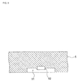
- FIG. 2 is an enlarged cross-sectional view of a part II of FIG. 1
- FIG. 3 is an enlarged cross-sectional view of a part III of FIG. 2
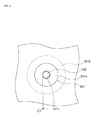
- FIG. 4 is a plan view seen from a direction IV of FIG. 3
- FIG. 5 is a cross-sectional view of principal parts which shows a modification of an injection molding mold in the present embodiment.
- the injection molding mold 1 in the present embodiment is, for example, a mold for molding a plastic molded part 5 which forms an actuator of a hard disk drive (part which holds a coil such as shown in FIG. 6 etc.)
- a plastic molded part 5 which forms an actuator of a hard disk drive (part which holds a coil such as shown in FIG. 6 etc.)
- a liquid crystal polymer (LCP) or polyphenylene sulfide (PPS) or other engineering plastic may be mentioned.
- This injection molding mold 1 as shown in FIG. 1 , comprises a fixed side mold 2 and a movable side mold 3.
- the fixed side mold 2 is a part in an injection molding mold 1 which is attached to a fixed side platen (not shown) of an injection molding machine.
- This fixed side mold 2 has a fixed side mold plate 21 which forms a cavity 4 with a movable side mold plate 31.
- the bottom surface of this fixed side mold plate 21 becomes a mating surface with the movable side mold plate 31, that is, a parting surface 211.
- the movable side mold 3 is a part in the injection molding mold 1 which is attached to a movable side platen of the injection molding machine (not shown) and is designed to approach or move away from the fixed side mold 2 along with movement of the movable side platen.
- This movable side mold 3 has a movable side mold plate 31, receiving plate 32, and gas escape mechanism 33.
- the movable side mold plate 31, as shown in FIG. 1 and FIG. 2 is a plate which abuts against the fixed side mold plate 21.
- the top surface constitutes a mating surface with the fixed side mold plate 21, that is, a parting surface 311.
- the parting surface 311 of this movable side mold plate 31 is formed with a first recess 312.
- the first recess 312 is shaped corresponding to the plastic molded part 5 and forms (defines) a cavity 4 with the fixed side mold plate 21.
- the first bottom surface 312a of this first recess 312 corresponds to the bottom surface of the later explained plastic molded part 5 shown in FIG. 6 .
- the first recess 312 is directly formed in the movable side mold plate 31, but it is also possible to form the first recess 312 in the core part and insert this core part into the movable side mold plate 31.
- the movable side mold plate 31 is formed with two engagement holes 313 which communicate with the first recess 312 and engage with sleeves 331 (explained later).
- the engagement holes 313 open at the first bottom surface 312a of the first recess 312.
- the receiving plate 32 is a plate which supports the movable side mold plate 31 and is stacked between the movable side mold plate 31 and a spacer block 34.
- This receiving plate 32 is formed with holding holes 321 which hold the flanges 331b of the sleeves 331 (explained later).
- this receiving plate 32 is formed with through holes 322 through which ejector pins 332 (explained later) can pass.
- the through holes 322 communicate with the holding holes 321 and are positioned on the same axes as the insertion holes 331c of the sleeves 331 (explained later). Further, the inside diameters of the through holes 322 are sufficiently larger than even the outside diameters of the ejector pins 332 and are smaller than even the outside diameters of the flanges 331b of the sleeves 331.
- the gas escape mechanisms 33 as shown in FIG. 2 and FIG. 3 , comprise the sleeves 331 and the ejector pins 332.
- Each sleeve 33 has a sleeve body 331a, a flange 331b, and an insertion hole 331c. Note that, the sleeve 331 is not formed integrally with the movable side mold plate 31, but is a separate part which can be attached to or detached from the movable side mold plate 31.
- Each flange 331b is a part in the sleeve 331 which locks with the movable side mold 31 and is positioned at the bottom of the sleeve body 331a.
- the outside diameter of the flange 331b is larger relative to the inside diameter of the engagement hole 313 and is smaller relative to the inside diameter of the holding hole 321 of the receiving plate 32.
- the thickness of the flange 331b is substantially the same as the depth of the holding hole 321 of the receiving plate 32 or somewhat lower than the depth of the holding hole 321. For this reason, the flange 331b is held in the holding hole 321.
- the sleeve 331 is fixed in place by the flange 331b being sandwiched between the bottom surface of the holding hole 321 and the bottom surface of the movable side mold plate 31.
- Each insertion hole 331c is a hole which passes through the sleeve 331 from the top surface (first end face 331d) to the bottom surface.
- the inside diameter of the insertion hole 331c is larger relative to the outside diameter of the ejector pin 332 (explained later). If the ejector pin 332 is inserted into the insertion hole 331c, a clearance C1 (for example, 5 ⁇ m or so) is formed between the inside surface of the insertion hole 331c and the side surface of the ejector pin 332.
- this clearance C1 is a ring shape along the inside surface of the insertion hole 331c and side surface of the ejector pin 332.
- Each ejector pin 332 is a member which pushes out the plastic molded part 5 which is molded in the cavity 4 (first recess 312) from the movable side mold 3.
- Each ejector pin 332, as shown in FIG. 1 is a pin-shaped part and, for example, has an outside diameter of 0.5 mm to 1.5 mm or so.
- This ejector pin 332 passes through a through hole 322 of the receiving plate 32 and is inserted into the insertion hole 331c of a sleeve 331. Further, the bottom end of the ejector pin 332 is fastened to the ejector plates 333a, 333b and pushes out the plastic molded part 5 which was molded inside the cavity 4 along with sliding movement of the ejector plates 333a, 333b (Z-direction in the figure).
- each ejector pin 332 is positioned on substantially the same plane L1 as the first end face 331d of a sleeve 331.
- the second end face 332a of the ejector pin 332 may also be made to stick out by exactly a predetermined height t 4 toward the inside of the cavity 4 compared with the first end face 331 d of the sleeve 331.
- the injection molding mold 1 comprises two ejector pins 332, but the invention is not particularly limited to this. Three or more ejector pins 332 may also be provided.
- all of the ejector pins 332 may comprise gas escape mechanisms 33 or part of the ejector pins 332 may comprise gas escape mechanisms 33.
- the plastic molded part 5 and the metal part may be integrally molded (insert molded).
- FIG. 6 is a cross-sectional view of a plastic molded part in the present embodiment
- FIG. 7 is an enlarged cross-sectional view of a part VII of FIG. 6
- FIG. 8 is a plan view seen from a direction VIII of FIG. 7
- FIG. 9 is a cross-sectional view showing a modification of the plastic molded part in the present embodiment.
- molten plastic is filled into the cavity 4 and, as shown in FIG. 6 , a plastic molded part 5 of a shape corresponding to the cavity 4 (first recess 312) is formed.
- a high pressure for example, 70 MPa to 80 MPa
- the gas which the molten plastic generates or the air which is sealed inside the cavity 4 escapes through each above-mentioned clearance C1 to the outside, while the molten plastic enters the clearance C1 whereby the plastic molded part 5 is formed with a burr 52.
- each sleeve 331 and engagement hole 313 are engaged. There is no clearance between the two.
- the plastic molded part 5 is formed with second recesses 51 corresponding to the sleeves 331 and ejector pins 332 of the injection molding mold 1.
- the depth t 5 of each second recess 51 is a depth commensurate with the height t 3 of each sleeve 331 and ejector pin 332 shown in FIG. 3 (t 3 ⁇ t 5 ).
- the second recess 51 of the plastic molded part 5 is a shape where the part surrounded by the burr 52 is further recessed.
- a burr 52 is formed at the inside from the outer circumference 511 a of a second bottom surface 511 of a second recess 51 in a ring shape when seen in a plan view. Further, the height t 6 of this burr 52 is the depth t 5 of the second recess 51 or less (t 6 ⁇ t 5 ), so the tip of the burr 52 (in FIG. 7 , the bottom end) is positioned inside the second recess 51. For this reason, even if the plastic molded part 5 is formed with a burr 52, the thickness h of the plastic molded part 5 is maintained and the plastic molded part 5 is precisely molded. Further, in the present embodiment, by forming the second recess 51 at a location not a problem in appearance at the plastic molded part 5, a burr 52 is allowed.
- the plastic molded part 5 is formed with a burr 52, the effect on the dimensional precision is suppressed as explained above, so it is possible to increase the above-mentioned clearance C1. Due to this, the gas which the molten plastic generates and the air which is sealed inside the cavity 4 are more proactively made to escape to the outside of the cavity 4, and transfer defects, short shots, and other molding defects become harder to occur.
- the burr 52 does not have to be removed. This means the productivity of the plastic molded part 5 is superior.
- the gas which is generated from the molten plastic is compressed inside the cavity 4 at a high temperature and a high pressure. Due to this, in the injection molding mold 1, the surface of the part which forms the cavity 4 sometimes corrodes. When the plastic part includes sulfur, such corrosion is particularly remarkable. As opposed to this, as explained above, by increasing the clearance C1 and proactively discharging the gas, such corrosion is suppressed.
- the sleeves 311 and the ejector pins 332 forming the clearances C1 easily corrode, but in such a case, the sleeves 331 and the ejector pins 332 may simply be replaced with new parts.
- These sleeves 331 and ejector pins 332 are small parts, so the cost of replacing the parts is low. In this way, in the present embodiment, lower cost can be achieved while maintaining safety of the injection molding mold 1.
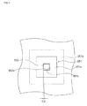
- FIG. 10 is a cross-sectional view of principal parts of an injection molding mold in the present embodiment, while FIG. 11 is a plan view seen from a direction XI of FIG. 10 .
- an insertion block 352 defining the cavity 4 comprises a gas escape mechanism 35.
- the second embodiment differs from the first embodiment, but the rest of the configuration is similar. Below, only the points which differ from the first embodiment will be explained. The parts of configurations similar to the first embodiment will be assigned the same reference notations and explanations omitted.
- the gas escape mechanism 35 in the present embodiment has a sleeve 351 and an insertion block 352.
- the sleeve 35 as shown in FIG. 10 and FIG. 11 , has a sleeve body 351a, a flange 351b, and an insertion hole 351c.
- the sleeve body 351a is a tubular shape with a rectangular cross-section.
- the flange 351b is also a rectangular shape corresponding to the sleeve body 351a.
- the cross-section of the insertion hole 351c is also rectangular. Further, in the same way as the first embodiment, the first end face 351d of the sleeve body 351a sticks out by the amount of height t 3 from the first bottom surface 312a of the first recess 312.
- the insertion block 352 as shown in FIG. 10 and FIG. 11 , has a block body 352a and a plate 352b.
- the block body 352a is inserted into the insertion hole 351c of the sleeve 351.
- the third end face 352c of this block body 352a sticks out from the first bottom surface 312a of the first recess 312 toward the inside of the cavity 4 and is positioned on substantially the same plane L2 as the first end face 351d of the sleeve 351. Note that, it is also possible to make the third end face 352c of the block body 352a stick out relatively toward the inside of the cavity 4 compared with the first end face 351d of the sleeve 351.
- the block body 352a is a rectangular shape when seen by a plan view and has a size somewhat smaller than the cross-section of the insertion hole 351c of the sleeve 351. For this reason, a clearance C2 is formed between the side surface of the block body 352a and the inside surface of the insertion hole 351 c. Note that, if such a clearance C2 is formed, the cross-sectional shape (seen from plan view) of the sleeve 351 or the insertion block 352 may also be made a circular shape.
- the plate 352b is connected at the center part with the block body 352a.
- the top surface abuts against the bottom surface of the flange 351b of the sleeve 351. Further, the bottom surface of the plate 352 contacts the bottom surface of the holding hole 321 of the receiving plate 32.
- the flange 351b of the sleeve 351 and the plate 352b of the insertion block 352 are fastened by being sandwiched between the bottom surface of the holding hole 321 of the receiving plate 32 and the bottom surface of the movable side mold plate 31.
- the sleeve 351 and the receiving plate 32 are formed with a passage which is communicated with the clearance C2. The gas which is generated by the molten plastic and the air which is sealed inside the cavity 4 escapes through this clearance C2 and the passage to the outside of the injection molding mold 1a.
- the gas escape mechanism is not limited to be provided at the movable side mold 3 and can also be provided at the fixed side mold 2. Further, when insert molding the plastic molded part 5 and a metal part (for example, carriage etc.) as one piece, instead of the ejector pin or insertion block or in addition to the ejector pin or insertion block, it is also possible to provide the above such gas escape mechanism at the core pin which positions the metal part.
- the engagement hole 313 is equivalent to one example of the through hole of the present invention
- the fixed side mold plate 21 and movable side mold plate 31 are equivalent to one example of the mold body of the present invention
- the sleeves 331, 351 are equivalent to one example of the tubular member of the present invention
- the ejector pin 332 or insertion block 352 is equivalent to one example of the insertion member of the present invention
- the first bottom surface 312a is equivalent to one example of a cavity surface of the present invention
- the second end face 332a and third end face 352c are equivalent to examples of the second end face of the present invention
- the second recess 51 is equivalent to one example of a recess of the present invention
- the second bottom surface 511 is equivalent to one example of the bottom surface of the present invention.
Landscapes
- Engineering & Computer Science (AREA)
- Manufacturing & Machinery (AREA)
- Mechanical Engineering (AREA)
- Moulds For Moulding Plastics Or The Like (AREA)
Abstract
Description
- The present invention relates to an injection molding mold which molds a plastic and to a plastic molded part which is formed by that injection molding mold.
- At the time of injection molding, the air which was sealed in the cavity of the injection molding mold and the gas which the molten plastic generates are compressed by the injected molten plastic inside of the cavity and escape from small clearances inside the injection molding mold.
- However, for example, when injecting molding a plastic such as an engineering plastic or other plastic with a high fluidity when molten, since the time until the cavity is filled with the plastic is short, the air or gas sometimes does not sufficiently escape. If such air or gas does not sufficiently escape from the cavity, it will become a cause of short shots, transfer defects, or other molding defects. As opposed to this, if just making the clearance inside the injection molding mold larger, there was the problem that leakage of plastic will easily occur from the clearance (burr) and the plastic molded part will suffer from defects in dimensions.
- The problem to be solved by the present invention is to provide an injection molding mold which enables accurate molding of a plastic molded part and a good precision plastic molded part.
- The injection molding mold according to the present invention is characterized by comprising: a mold body in which a through hole which communicates with a cavity is formed; a tubular member which is engaged with the through hole; and an insertion member which is inserted into the tubular member with a predetermined clearance, wherein the first end face of the tubular member and the second end face of the insertion member stick out from the cavity surface defining the cavity.
- In the above invention, the second end face may stick out from the first end face or be positioned on substantially the same plane as the first end face.
- In the above invention, the tubular member can be attached to or detached from the mold body, and the insertion member can be attached to or detached from the tubular member.
- The plastic molded part according to the present invention is a plastic molded part which has a recess, characterized in that a tubular burr is formed at an inside from an outer circumference of a bottom surface of the recess and a tip of the burr is positioned inside of the recess.
- According to the present invention, the first end face of the tubular member and the second end face of the insertion member stick out from the cavity surface, so the plastic molded part can be molded with a better precision.
-
- [
FIG. 1] FIG. 1 is a cross-sectional perspective view of an injection molding mold in a first embodiment of the present invention. - [
FIG. 2] FIG. 2 is an enlarged cross-sectional view of a part II ofFIG. 1 . - [
FIG. 3] FIG. 3 is an enlarged cross-sectional view of a part III ofFIG. 2 . - [
FIG. 4] FIG. 4 is a plan view seen from a direction IV ofFIG. 3 . - [
FIG. 5] FIG. 5 is a cross-sectional view of principal parts which shows a modification of an injection molding mold in the first embodiment of the present invention. - [
FIG. 6] FIG. 6 is a cross-sectional view of a plastic molded part in the first embodiment of the present invention. - [
FIG. 7] FIG. 7 is an enlarged cross-sectional view of a part VII ofFIG. 6 . - [
FIG. 8] FIG. 8 is a plan view seen from a direction VIII ofFIG. 7 . - [
FIG. 9] FIG. 9 is a cross-sectional view which shows a modification of a plastic molded part in the first embodiment of the present invention. - [
FIG. 10] FIG. 10 is a cross-sectional view of principal parts of a second embodiment of the present invention. - [
FIG. 11] FIG. 11 is a plan view seen from a direction XI ofFIG. 10 . - Below, embodiments of the present invention will be explained based on the drawings.
-
FIG. 1 is a cross-sectional perspective view of an injection molding mold in the present embodiment,FIG. 2 is an enlarged cross-sectional view of a part II ofFIG. 1 ,FIG. 3 is an enlarged cross-sectional view of a part III ofFIG. 2 ,FIG. 4 is a plan view seen from a direction IV ofFIG. 3 , andFIG. 5 is a cross-sectional view of principal parts which shows a modification of an injection molding mold in the present embodiment. - The injection molding mold 1 in the present embodiment is, for example, a mold for molding a plastic molded
part 5 which forms an actuator of a hard disk drive (part which holds a coil such as shown inFIG. 6 etc.) As the plastic which forms the plastic moldedpart 5, for example, a liquid crystal polymer (LCP) or polyphenylene sulfide (PPS) or other engineering plastic may be mentioned. - This injection molding mold 1, as shown in
FIG. 1 , comprises afixed side mold 2 and amovable side mold 3. - The fixed
side mold 2 is a part in an injection molding mold 1 which is attached to a fixed side platen (not shown) of an injection molding machine. This fixedside mold 2 has a fixedside mold plate 21 which forms acavity 4 with a movableside mold plate 31. The bottom surface of this fixedside mold plate 21 becomes a mating surface with the movableside mold plate 31, that is, aparting surface 211. - The
movable side mold 3 is a part in the injection molding mold 1 which is attached to a movable side platen of the injection molding machine (not shown) and is designed to approach or move away from thefixed side mold 2 along with movement of the movable side platen. Thismovable side mold 3 has a movableside mold plate 31, receivingplate 32, andgas escape mechanism 33. - The movable
side mold plate 31, as shown inFIG. 1 andFIG. 2 , is a plate which abuts against the fixedside mold plate 21. The top surface constitutes a mating surface with the fixedside mold plate 21, that is, aparting surface 311. - The
parting surface 311 of this movableside mold plate 31 is formed with afirst recess 312. Thefirst recess 312 is shaped corresponding to the plastic moldedpart 5 and forms (defines) acavity 4 with the fixedside mold plate 21. Note that, thefirst bottom surface 312a of thisfirst recess 312 corresponds to the bottom surface of the later explained plastic moldedpart 5 shown inFIG. 6 . Here, in the present embodiment, thefirst recess 312 is directly formed in the movableside mold plate 31, but it is also possible to form thefirst recess 312 in the core part and insert this core part into the movableside mold plate 31. - Further, the movable
side mold plate 31, as shown inFIG. 2 andFIG. 3 , is formed with twoengagement holes 313 which communicate with thefirst recess 312 and engage with sleeves 331 (explained later). Theengagement holes 313 open at thefirst bottom surface 312a of thefirst recess 312. - As shown in
FIG. 1 , thereceiving plate 32 is a plate which supports the movableside mold plate 31 and is stacked between the movableside mold plate 31 and aspacer block 34. - This receiving
plate 32, as shown inFIG. 2 andFIG. 3 , is formed withholding holes 321 which hold theflanges 331b of the sleeves 331 (explained later). - Further, this receiving
plate 32 is formed with throughholes 322 through which ejector pins 332 (explained later) can pass. The throughholes 322 communicate with theholding holes 321 and are positioned on the same axes as theinsertion holes 331c of the sleeves 331 (explained later). Further, the inside diameters of the throughholes 322 are sufficiently larger than even the outside diameters of theejector pins 332 and are smaller than even the outside diameters of theflanges 331b of thesleeves 331. - The
gas escape mechanisms 33, as shown inFIG. 2 andFIG. 3 , comprise thesleeves 331 and theejector pins 332. - Each
sleeve 331, as shown inFIG. 3 , has asleeve body 331a, aflange 331b, and aninsertion hole 331c. Note that, thesleeve 331 is not formed integrally with the movableside mold plate 31, but is a separate part which can be attached to or detached from the movableside mold plate 31. - Each
sleeve body 331 a is a cylindrical member and has an outside diameter enabling it to fit into anengagement hole 313 of the movableside mold plate 31. Further, as shown in the figure, the height t1 of thissleeve body 331a is larger relative to the thickness t2 of the movableside mold plate 31 in the first recess 312 (t1>t2). For this reason, thefirst end face 331d of thesleeve body 331a (top end in figure) sticks out from thefirst bottom surface 312a of thefirst recess 312 by the amount of the height t3 (t3=t1-t2, for example, 20 µm to 30 µm or so). - Each
flange 331b is a part in thesleeve 331 which locks with themovable side mold 31 and is positioned at the bottom of thesleeve body 331a. The outside diameter of theflange 331b is larger relative to the inside diameter of theengagement hole 313 and is smaller relative to the inside diameter of theholding hole 321 of thereceiving plate 32. Further, the thickness of theflange 331b is substantially the same as the depth of theholding hole 321 of thereceiving plate 32 or somewhat lower than the depth of theholding hole 321. For this reason, theflange 331b is held in theholding hole 321. Thesleeve 331 is fixed in place by theflange 331b being sandwiched between the bottom surface of theholding hole 321 and the bottom surface of the movableside mold plate 31. - Each
insertion hole 331c, as shown inFIG. 3 , is a hole which passes through thesleeve 331 from the top surface (first end face 331d) to the bottom surface. The inside diameter of theinsertion hole 331c is larger relative to the outside diameter of the ejector pin 332 (explained later). If theejector pin 332 is inserted into theinsertion hole 331c, a clearance C1 (for example, 5 µm or so) is formed between the inside surface of theinsertion hole 331c and the side surface of theejector pin 332. Due to this, at the time of injection molding, the gas which is generated by the molten plastic and the air which is sealed inside thecavity 4 escape through this clearance C 1 from thecavity 4 to the outside. Note that, this clearance C1, as shown inFIG. 4 , is a ring shape along the inside surface of theinsertion hole 331c and side surface of theejector pin 332. - Each
ejector pin 332 is a member which pushes out the plastic moldedpart 5 which is molded in the cavity 4 (first recess 312) from themovable side mold 3. - Each
ejector pin 332, as shown inFIG. 1 , is a pin-shaped part and, for example, has an outside diameter of 0.5 mm to 1.5 mm or so. Thisejector pin 332 passes through a throughhole 322 of the receivingplate 32 and is inserted into theinsertion hole 331c of asleeve 331. Further, the bottom end of theejector pin 332 is fastened to theejector plates part 5 which was molded inside thecavity 4 along with sliding movement of theejector plates - Here, as shown in
FIG. 3 , thesecond end face 332a (top end) of eachejector pin 332 is positioned on substantially the same plane L1 as thefirst end face 331d of asleeve 331. Note that, thesecond end face 332a of theejector pin 332, as shown inFIG. 5 , may also be made to stick out by exactly a predetermined height t4 toward the inside of thecavity 4 compared with thefirst end face 331 d of thesleeve 331. - Note that, in the present embodiment, the injection molding mold 1 comprises two
ejector pins 332, but the invention is not particularly limited to this. Three or more ejector pins 332 may also be provided. Here, all of the ejector pins 332 may comprisegas escape mechanisms 33 or part of the ejector pins 332 may comprisegas escape mechanisms 33. Further, the plastic moldedpart 5 and the metal part (for example, carriage of actuator etc.) may be integrally molded (insert molded). - Next, the action of the embodiment will be explained.
-
FIG. 6 is a cross-sectional view of a plastic molded part in the present embodiment,FIG. 7 is an enlarged cross-sectional view of a part VII ofFIG. 6 ,FIG. 8 is a plan view seen from a direction VIII ofFIG. 7 , andFIG. 9 is a cross-sectional view showing a modification of the plastic molded part in the present embodiment. - If injecting molten plastic into the injection molding mold 1 in the present embodiment through an injection port X (see
FIG. 1 ) at a high pressure (for example, 70 MPa to 80 MPa), the molten plastic is filled into thecavity 4 and, as shown inFIG. 6 , a plastic moldedpart 5 of a shape corresponding to the cavity 4 (first recess 312) is formed. At this time, the gas which the molten plastic generates or the air which is sealed inside thecavity 4 escapes through each above-mentioned clearance C1 to the outside, while the molten plastic enters the clearance C1 whereby the plastic moldedpart 5 is formed with aburr 52. Here, eachsleeve 331 andengagement hole 313 are engaged. There is no clearance between the two. No burr is formed between thesleeve 331 and theengagement hole 313. Note that, the air or gas which escapes from the clearance C1 passes through the clearance between each throughhole 322 of the receivingplate 32 and eachejector pin 332 and escapes to the outside of the injection molding mold 1. - In the present embodiment, as shown in
FIG. 6 andFIG. 7 , the plastic moldedpart 5 is formed withsecond recesses 51 corresponding to thesleeves 331 and ejector pins 332 of the injection molding mold 1. The depth t5 of eachsecond recess 51 is a depth commensurate with the height t3 of eachsleeve 331 andejector pin 332 shown inFIG. 3 (t3≒t5). - Note that, as shown in
FIG. 5 , when asecond end face 332a of anejector pin 332 sticks out from afirst end face 331d of asleeve 331, thesecond recess 51 of the plastic moldedpart 5, as shown inFIG. 9 , is a shape where the part surrounded by theburr 52 is further recessed. - A
burr 52, as shown inFIG. 7 andFIG. 8 , is formed at the inside from theouter circumference 511 a of a secondbottom surface 511 of asecond recess 51 in a ring shape when seen in a plan view. Further, the height t6 of thisburr 52 is the depth t5 of thesecond recess 51 or less (t6≦t5), so the tip of the burr 52 (inFIG. 7 , the bottom end) is positioned inside thesecond recess 51. For this reason, even if the plastic moldedpart 5 is formed with aburr 52, the thickness h of the plastic moldedpart 5 is maintained and the plastic moldedpart 5 is precisely molded. Further, in the present embodiment, by forming thesecond recess 51 at a location not a problem in appearance at the plastic moldedpart 5, aburr 52 is allowed. - Further, even if the plastic molded
part 5 is formed with aburr 52, the effect on the dimensional precision is suppressed as explained above, so it is possible to increase the above-mentioned clearance C1. Due to this, the gas which the molten plastic generates and the air which is sealed inside thecavity 4 are more proactively made to escape to the outside of thecavity 4, and transfer defects, short shots, and other molding defects become harder to occur. - Further, in the present embodiment, even if the plastic molded
part 5 ends up with aburr 52, theburr 52 does not have to be removed. This means the productivity of the plastic moldedpart 5 is superior. - Here, the gas which is generated from the molten plastic is compressed inside the
cavity 4 at a high temperature and a high pressure. Due to this, in the injection molding mold 1, the surface of the part which forms thecavity 4 sometimes corrodes. When the plastic part includes sulfur, such corrosion is particularly remarkable. As opposed to this, as explained above, by increasing the clearance C1 and proactively discharging the gas, such corrosion is suppressed. - On the other hand, by enabling a large amount of gas escape from the clearance C1, the
sleeves 311 and the ejector pins 332 forming the clearances C1 easily corrode, but in such a case, thesleeves 331 and the ejector pins 332 may simply be replaced with new parts. Thesesleeves 331 and ejector pins 332 are small parts, so the cost of replacing the parts is low. In this way, in the present embodiment, lower cost can be achieved while maintaining safety of the injection molding mold 1. - Next, a second embodiment will be explained.
-
FIG. 10 is a cross-sectional view of principal parts of an injection molding mold in the present embodiment, whileFIG. 11 is a plan view seen from a direction XI ofFIG. 10 . - In an injection molding mold 1a in the present embodiment, an
insertion block 352 defining thecavity 4 comprises a gas escape mechanism 35. On this point, the second embodiment differs from the first embodiment, but the rest of the configuration is similar. Below, only the points which differ from the first embodiment will be explained. The parts of configurations similar to the first embodiment will be assigned the same reference notations and explanations omitted. - The gas escape mechanism 35 in the present embodiment, as shown in
FIG. 10 andFIG. 11 , has asleeve 351 and aninsertion block 352. - The
sleeve 351, as shown inFIG. 10 andFIG. 11 , has asleeve body 351a, aflange 351b, and aninsertion hole 351c. - The
sleeve body 351a is a tubular shape with a rectangular cross-section. Theflange 351b is also a rectangular shape corresponding to thesleeve body 351a. Further, the cross-section of theinsertion hole 351c is also rectangular. Further, in the same way as the first embodiment, thefirst end face 351d of thesleeve body 351a sticks out by the amount of height t3 from thefirst bottom surface 312a of thefirst recess 312. - The
insertion block 352, as shown inFIG. 10 andFIG. 11 , has ablock body 352a and aplate 352b. - The
block body 352a is inserted into theinsertion hole 351c of thesleeve 351. Thethird end face 352c of thisblock body 352a sticks out from thefirst bottom surface 312a of thefirst recess 312 toward the inside of thecavity 4 and is positioned on substantially the same plane L2 as thefirst end face 351d of thesleeve 351. Note that, it is also possible to make thethird end face 352c of theblock body 352a stick out relatively toward the inside of thecavity 4 compared with thefirst end face 351d of thesleeve 351. - Further, the
block body 352a, as shown inFIG. 11 , is a rectangular shape when seen by a plan view and has a size somewhat smaller than the cross-section of theinsertion hole 351c of thesleeve 351. For this reason, a clearance C2 is formed between the side surface of theblock body 352a and the inside surface of theinsertion hole 351 c. Note that, if such a clearance C2 is formed, the cross-sectional shape (seen from plan view) of thesleeve 351 or theinsertion block 352 may also be made a circular shape. - The
plate 352b is connected at the center part with theblock body 352a. The top surface abuts against the bottom surface of theflange 351b of thesleeve 351. Further, the bottom surface of theplate 352 contacts the bottom surface of the holdinghole 321 of the receivingplate 32. - In the present embodiment, as shown in
FIG. 10 , theflange 351b of thesleeve 351 and theplate 352b of theinsertion block 352 are fastened by being sandwiched between the bottom surface of the holdinghole 321 of the receivingplate 32 and the bottom surface of the movableside mold plate 31. Further, while not particularly shown, thesleeve 351 and the receivingplate 32 are formed with a passage which is communicated with the clearance C2. The gas which is generated by the molten plastic and the air which is sealed inside thecavity 4 escapes through this clearance C2 and the passage to the outside of the injection molding mold 1a. - In the present embodiment, by adopting such a gas escape mechanism 35, an effect similar to that of the first embodiment can be obtained. Further, by providing, in addition to the
ejector pin 332, a gas escape mechanism in theinsertion block 352, it is possible to provide numerous gas escape mechanisms in the injection molding mold and possible to make the gas which the molten plastic generates or the air which is sealed in thecavity 4 be further proactively discharged to the outside. - Note that, the gas escape mechanism is not limited to be provided at the
movable side mold 3 and can also be provided at the fixedside mold 2. Further, when insert molding the plastic moldedpart 5 and a metal part (for example, carriage etc.) as one piece, instead of the ejector pin or insertion block or in addition to the ejector pin or insertion block, it is also possible to provide the above such gas escape mechanism at the core pin which positions the metal part. - Note that, in the above explained embodiment, the
engagement hole 313 is equivalent to one example of the through hole of the present invention, the fixedside mold plate 21 and movableside mold plate 31 are equivalent to one example of the mold body of the present invention, thesleeves ejector pin 332 orinsertion block 352 is equivalent to one example of the insertion member of the present invention, thefirst bottom surface 312a is equivalent to one example of a cavity surface of the present invention, thesecond end face 332a andthird end face 352c are equivalent to examples of the second end face of the present invention, thesecond recess 51 is equivalent to one example of a recess of the present invention, and the secondbottom surface 511 is equivalent to one example of the bottom surface of the present invention. - Note that the embodiments explained above were described for facilitating understanding of the present invention and were not described for limiting the present invention. Therefore, the elements disclosed in the above embodiments include all design modifications and equivalents falling under the technical scope of the present invention.
-
- 1, 1a... injection molding mold
- 2... fixed side mold
- 21... fixed side mold plate
- 3... movable side mold
- 31... movable side mold plate
- 312... first recess
- 312a... first bottom surface
- 313... engagement hole
- 312... first recess
- 33, 35... gas escape mechanism
- 331, 351... sleeve
- 331a, 351a... sleeve body
- 331b, 351b... flange
- 331c, 351c... insertion hole
- 331d, 351d... first end face
- 332... ejector pin
- 332a... second end face
- 352... insertion block
- 352a... block body
- 352b... plate
- 352c... third end face
- 331, 351... sleeve
- 31... movable side mold plate
- 4... cavity
- 5... plastic molded part
- 51... second recess
- 511... second bottom surface
- 52... burr
- 51... second recess
Claims (4)
- An injection molding mold characterized by comprising:a mold body in which a through hole which communicates with a cavity is formed;a tubular member which is engaged with the through hole; andan insertion member which is inserted into the tubular member with a predetermined clearance, whereinthe first end face of the tubular member and the second end face of the insertion member stick out from the cavity surface defining the cavity.
- An injection molding mold as set forth in claim 1, characterized in that the second end face sticks out from the first end face or is positioned on substantially the same plane as the first end face.
- An injection molding mold as set forth in claim 1 or 2, characterized in that the tubular member can be attached to or detached from the mold body, and the insertion member can be attached to or detached from the tubular member.
- A plastic molded part which has a recess, characterized in that
a tubular burr is formed at an inside from an outer circumference of a bottom surface of the recess and
a tip of the burr is positioned inside of the recess.
Applications Claiming Priority (2)
| Application Number | Priority Date | Filing Date | Title |
|---|---|---|---|
| JP2009265944 | 2009-11-24 | ||
| PCT/JP2010/069713 WO2011065205A1 (en) | 2009-11-24 | 2010-11-05 | Injection molding die and resin molded product |
Publications (2)
| Publication Number | Publication Date |
|---|---|
| EP2505333A1 true EP2505333A1 (en) | 2012-10-03 |
| EP2505333A4 EP2505333A4 (en) | 2013-06-12 |
Family
ID=44066308
Family Applications (1)
| Application Number | Title | Priority Date | Filing Date |
|---|---|---|---|
| EP10833052.3A Withdrawn EP2505333A4 (en) | 2009-11-24 | 2010-11-05 | Injection molding die and resin molded product |
Country Status (5)
| Country | Link |
|---|---|
| US (1) | US20120231229A1 (en) |
| EP (1) | EP2505333A4 (en) |
| JP (1) | JPWO2011065205A1 (en) |
| CN (1) | CN102666063A (en) |
| WO (1) | WO2011065205A1 (en) |
Families Citing this family (1)
| Publication number | Priority date | Publication date | Assignee | Title |
|---|---|---|---|---|
| US11020880B2 (en) | 2016-08-01 | 2021-06-01 | Hubbell Incorporated | Mold and method for forming a molded part |
Family Cites Families (18)
| Publication number | Priority date | Publication date | Assignee | Title |
|---|---|---|---|---|
| US3754846A (en) * | 1972-01-21 | 1973-08-28 | Cpi Inc | Apparatus for single cavity injection molding of oil seals |
| US4347212A (en) * | 1980-08-26 | 1982-08-31 | Corn States Metal Fabricators, Inc. | Method for forming a tire |
| US4351789A (en) * | 1981-07-27 | 1982-09-28 | The B. F. Goodrich Company | Mold and process for molding |
| JPH022566Y2 (en) * | 1986-12-13 | 1990-01-22 | ||
| JPH0592450A (en) * | 1991-10-03 | 1993-04-16 | Fuji Electric Co Ltd | Transfer molds and molded products with igi ectapine |
| JPH05278077A (en) * | 1992-04-02 | 1993-10-26 | Fuji Electric Co Ltd | Mold for transfer molding |
| JP2528258B2 (en) * | 1993-10-18 | 1996-08-28 | 自動車部品栄和協同組合 | Degassing structure of injection mold |
| JPH07214600A (en) * | 1994-02-02 | 1995-08-15 | Fuji Electric Co Ltd | Mold for molding transparent resin-sealed semiconductor device |
| US5972276A (en) * | 1996-10-04 | 1999-10-26 | Asahi Kasei Kogyo Kabushiki Kaisha | Method for the injection molding of a resin |
| JP3116906B2 (en) * | 1998-05-26 | 2000-12-11 | 日本電気株式会社 | Mold for resin sealing |
| JP4085182B2 (en) * | 2000-06-16 | 2008-05-14 | 有限会社 サンエイ・モールド | Extrusion pin in injection molding |
| JP3932938B2 (en) * | 2002-03-20 | 2007-06-20 | 双葉電子工業株式会社 | Injection mold and injection mold pin |
| JP4321078B2 (en) * | 2003-02-28 | 2009-08-26 | コニカミノルタホールディングス株式会社 | Molded lens |
| JP4300945B2 (en) * | 2003-09-03 | 2009-07-22 | 株式会社ブリヂストン | Mold for foam molding and method for producing urethane foam |
| US7114944B2 (en) * | 2004-01-21 | 2006-10-03 | David Wolfe Design, Inc | Tactical venting |
| JP2007307805A (en) * | 2006-05-18 | 2007-11-29 | Fuji Electric Device Technology Co Ltd | Semiconductor package manufacturing apparatus, semiconductor package manufacturing method, and semiconductor package |
| JP2008000995A (en) * | 2006-06-22 | 2008-01-10 | Nidec Sankyo Corp | Manufacturing method for bonded article made of resin, molding die, and resin bonded article |
| JP4600461B2 (en) * | 2007-11-06 | 2010-12-15 | 三菱電機株式会社 | Manufacturing method of molded products |
-
2010
- 2010-11-05 CN CN2010800527927A patent/CN102666063A/en active Pending
- 2010-11-05 JP JP2011543194A patent/JPWO2011065205A1/en active Pending
- 2010-11-05 EP EP10833052.3A patent/EP2505333A4/en not_active Withdrawn
- 2010-11-05 WO PCT/JP2010/069713 patent/WO2011065205A1/en not_active Ceased
-
2012
- 2012-05-23 US US13/478,407 patent/US20120231229A1/en not_active Abandoned
Also Published As
| Publication number | Publication date |
|---|---|
| WO2011065205A1 (en) | 2011-06-03 |
| JPWO2011065205A1 (en) | 2013-04-11 |
| CN102666063A (en) | 2012-09-12 |
| EP2505333A4 (en) | 2013-06-12 |
| US20120231229A1 (en) | 2012-09-13 |
Similar Documents
| Publication | Publication Date | Title |
|---|---|---|
| CN101905498A (en) | Mould | |
| US20120306972A1 (en) | Injection molding method, injection-molded product, optical element, optical prism, ink tank, recording device, and injection mold | |
| US20100316755A1 (en) | Mold assembly for making light guide plate | |
| CN102582032B (en) | Mold for injection molding, and injection molding method, and injection molding machine using the mold for injection molding | |
| US7891965B2 (en) | Mold | |
| US20120231229A1 (en) | Injection molding mold and plastic molded part | |
| EP2090417B1 (en) | Seal ring | |
| US7594808B2 (en) | Mold and molding method | |
| KR101360770B1 (en) | A double injection mould having angular pins and sliding cores for reinforcing structural weak parts in a mould | |
| JP4291199B2 (en) | Mold for separator molding for fuel cell | |
| JP2005205807A (en) | Injection mold | |
| KR102927676B1 (en) | Gauge for checking mold parting line | |
| JP5760555B2 (en) | Aperture array manufacturing apparatus and manufacturing method | |
| US12623381B2 (en) | Injection molding method for resin molded product and injection molding apparatus | |
| CN114102970A (en) | Insert molding device and molding method | |
| CN206316362U (en) | A kind of active and inactive mold locking-positioning structure of die casting | |
| CN103507217B (en) | Shaped device and method of operating thereof | |
| JPH035114A (en) | Mold structure for resin molding | |
| CN223657535U (en) | An injection mold for an in-vehicle wiring harness bracket | |
| KR20250119904A (en) | Injection mold device and manufacturing method thereof | |
| CN216885013U (en) | Slide mechanism and injection mold | |
| JP2008162213A (en) | Injection molding mold | |
| JP2007136823A (en) | Undercut core movable fitting, movable slider, jig for mobility, and double molding mold having them | |
| CN210999696U (en) | A mold assembly for hot-pressed plastic lenses | |
| JP4936935B2 (en) | Plastic molding device for plastic optical element and resin molding method |
Legal Events
| Date | Code | Title | Description |
|---|---|---|---|
| PUAI | Public reference made under article 153(3) epc to a published international application that has entered the european phase |
Free format text: ORIGINAL CODE: 0009012 |
|
| 17P | Request for examination filed |
Effective date: 20120503 |
|
| AK | Designated contracting states |
Kind code of ref document: A1 Designated state(s): AL AT BE BG CH CY CZ DE DK EE ES FI FR GB GR HR HU IE IS IT LI LT LU LV MC MK MT NL NO PL PT RO RS SE SI SK SM TR |
|
| DAX | Request for extension of the european patent (deleted) | ||
| A4 | Supplementary search report drawn up and despatched |
Effective date: 20130513 |
|
| RIC1 | Information provided on ipc code assigned before grant |
Ipc: B29C 45/00 20060101ALI20130506BHEP Ipc: B29C 45/40 20060101ALI20130506BHEP Ipc: B29C 45/34 20060101AFI20130506BHEP |
|
| STAA | Information on the status of an ep patent application or granted ep patent |
Free format text: STATUS: THE APPLICATION IS DEEMED TO BE WITHDRAWN |
|
| 18D | Application deemed to be withdrawn |
Effective date: 20131211 |