EP2505289A1 - Rotation tool - Google Patents
Rotation tool Download PDFInfo
- Publication number
- EP2505289A1 EP2505289A1 EP10833314A EP10833314A EP2505289A1 EP 2505289 A1 EP2505289 A1 EP 2505289A1 EP 10833314 A EP10833314 A EP 10833314A EP 10833314 A EP10833314 A EP 10833314A EP 2505289 A1 EP2505289 A1 EP 2505289A1
- Authority
- EP
- European Patent Office
- Prior art keywords
- hard phase
- peak
- sintered cermet
- phase
- cermet
- Prior art date
- Legal status (The legal status is an assumption and is not a legal conclusion. Google has not performed a legal analysis and makes no representation as to the accuracy of the status listed.)
- Granted
Links
Images


Classifications
-
- B—PERFORMING OPERATIONS; TRANSPORTING
- B22—CASTING; POWDER METALLURGY
- B22F—WORKING METALLIC POWDER; MANUFACTURE OF ARTICLES FROM METALLIC POWDER; MAKING METALLIC POWDER; APPARATUS OR DEVICES SPECIALLY ADAPTED FOR METALLIC POWDER
- B22F3/00—Manufacture of workpieces or articles from metallic powder characterised by the manner of compacting or sintering; Apparatus specially adapted therefor ; Presses and furnaces
- B22F3/10—Sintering only
- B22F3/1003—Use of special medium during sintering, e.g. sintering aid
- B22F3/1007—Atmosphere
- B22F3/101—Changing atmosphere
-
- C—CHEMISTRY; METALLURGY
- C22—METALLURGY; FERROUS OR NON-FERROUS ALLOYS; TREATMENT OF ALLOYS OR NON-FERROUS METALS
- C22C—ALLOYS
- C22C29/00—Alloys based on carbides, oxides, nitrides, borides, or silicides, e.g. cermets, or other metal compounds, e.g. oxynitrides, sulfides
- C22C29/02—Alloys based on carbides, oxides, nitrides, borides, or silicides, e.g. cermets, or other metal compounds, e.g. oxynitrides, sulfides based on carbides or carbonitrides
-
- B—PERFORMING OPERATIONS; TRANSPORTING
- B22—CASTING; POWDER METALLURGY
- B22F—WORKING METALLIC POWDER; MANUFACTURE OF ARTICLES FROM METALLIC POWDER; MAKING METALLIC POWDER; APPARATUS OR DEVICES SPECIALLY ADAPTED FOR METALLIC POWDER
- B22F2203/00—Controlling
- B22F2203/11—Controlling temperature, temperature profile
-
- B—PERFORMING OPERATIONS; TRANSPORTING
- B22—CASTING; POWDER METALLURGY
- B22F—WORKING METALLIC POWDER; MANUFACTURE OF ARTICLES FROM METALLIC POWDER; MAKING METALLIC POWDER; APPARATUS OR DEVICES SPECIALLY ADAPTED FOR METALLIC POWDER
- B22F2207/00—Aspects of the compositions, gradients
- B22F2207/01—Composition gradients
-
- B—PERFORMING OPERATIONS; TRANSPORTING
- B22—CASTING; POWDER METALLURGY
- B22F—WORKING METALLIC POWDER; MANUFACTURE OF ARTICLES FROM METALLIC POWDER; MAKING METALLIC POWDER; APPARATUS OR DEVICES SPECIALLY ADAPTED FOR METALLIC POWDER
- B22F2999/00—Aspects linked to processes or compositions used in powder metallurgy
-
- B—PERFORMING OPERATIONS; TRANSPORTING
- B22—CASTING; POWDER METALLURGY
- B22F—WORKING METALLIC POWDER; MANUFACTURE OF ARTICLES FROM METALLIC POWDER; MAKING METALLIC POWDER; APPARATUS OR DEVICES SPECIALLY ADAPTED FOR METALLIC POWDER
- B22F3/00—Manufacture of workpieces or articles from metallic powder characterised by the manner of compacting or sintering; Apparatus specially adapted therefor ; Presses and furnaces
- B22F3/10—Sintering only
- B22F3/1017—Multiple heating or additional steps
-
- B—PERFORMING OPERATIONS; TRANSPORTING
- B23—MACHINE TOOLS; METAL-WORKING NOT OTHERWISE PROVIDED FOR
- B23B—TURNING; BORING
- B23B2222/00—Materials of tools or workpieces composed of metals, alloys or metal matrices
- B23B2222/16—Cermet
-
- B—PERFORMING OPERATIONS; TRANSPORTING
- B23—MACHINE TOOLS; METAL-WORKING NOT OTHERWISE PROVIDED FOR
- B23C—MILLING
- B23C2222/00—Materials of tools or workpieces composed of metals, alloys or metal matrices
- B23C2222/16—Cermet
-
- Y—GENERAL TAGGING OF NEW TECHNOLOGICAL DEVELOPMENTS; GENERAL TAGGING OF CROSS-SECTIONAL TECHNOLOGIES SPANNING OVER SEVERAL SECTIONS OF THE IPC; TECHNICAL SUBJECTS COVERED BY FORMER USPC CROSS-REFERENCE ART COLLECTIONS [XRACs] AND DIGESTS
- Y10—TECHNICAL SUBJECTS COVERED BY FORMER USPC
- Y10T—TECHNICAL SUBJECTS COVERED BY FORMER US CLASSIFICATION
- Y10T407/00—Cutters, for shaping
- Y10T407/27—Cutters, for shaping comprising tool of specific chemical composition
-
- Y—GENERAL TAGGING OF NEW TECHNOLOGICAL DEVELOPMENTS; GENERAL TAGGING OF CROSS-SECTIONAL TECHNOLOGIES SPANNING OVER SEVERAL SECTIONS OF THE IPC; TECHNICAL SUBJECTS COVERED BY FORMER USPC CROSS-REFERENCE ART COLLECTIONS [XRACs] AND DIGESTS
- Y10—TECHNICAL SUBJECTS COVERED BY FORMER USPC
- Y10T—TECHNICAL SUBJECTS COVERED BY FORMER US CLASSIFICATION
- Y10T428/00—Stock material or miscellaneous articles
- Y10T428/12—All metal or with adjacent metals
- Y10T428/12458—All metal or with adjacent metals having composition, density, or hardness gradient
-
- Y—GENERAL TAGGING OF NEW TECHNOLOGICAL DEVELOPMENTS; GENERAL TAGGING OF CROSS-SECTIONAL TECHNOLOGIES SPANNING OVER SEVERAL SECTIONS OF THE IPC; TECHNICAL SUBJECTS COVERED BY FORMER USPC CROSS-REFERENCE ART COLLECTIONS [XRACs] AND DIGESTS
- Y10—TECHNICAL SUBJECTS COVERED BY FORMER USPC
- Y10T—TECHNICAL SUBJECTS COVERED BY FORMER US CLASSIFICATION
- Y10T428/00—Stock material or miscellaneous articles
- Y10T428/12—All metal or with adjacent metals
- Y10T428/12493—Composite; i.e., plural, adjacent, spatially distinct metal components [e.g., layers, joint, etc.]
- Y10T428/12535—Composite; i.e., plural, adjacent, spatially distinct metal components [e.g., layers, joint, etc.] with additional, spatially distinct nonmetal component
- Y10T428/12542—More than one such component
-
- Y—GENERAL TAGGING OF NEW TECHNOLOGICAL DEVELOPMENTS; GENERAL TAGGING OF CROSS-SECTIONAL TECHNOLOGIES SPANNING OVER SEVERAL SECTIONS OF THE IPC; TECHNICAL SUBJECTS COVERED BY FORMER USPC CROSS-REFERENCE ART COLLECTIONS [XRACs] AND DIGESTS
- Y10—TECHNICAL SUBJECTS COVERED BY FORMER USPC
- Y10T—TECHNICAL SUBJECTS COVERED BY FORMER US CLASSIFICATION
- Y10T428/00—Stock material or miscellaneous articles
- Y10T428/12—All metal or with adjacent metals
- Y10T428/12493—Composite; i.e., plural, adjacent, spatially distinct metal components [e.g., layers, joint, etc.]
- Y10T428/12535—Composite; i.e., plural, adjacent, spatially distinct metal components [e.g., layers, joint, etc.] with additional, spatially distinct nonmetal component
- Y10T428/12576—Boride, carbide or nitride component
-
- Y—GENERAL TAGGING OF NEW TECHNOLOGICAL DEVELOPMENTS; GENERAL TAGGING OF CROSS-SECTIONAL TECHNOLOGIES SPANNING OVER SEVERAL SECTIONS OF THE IPC; TECHNICAL SUBJECTS COVERED BY FORMER USPC CROSS-REFERENCE ART COLLECTIONS [XRACs] AND DIGESTS
- Y10—TECHNICAL SUBJECTS COVERED BY FORMER USPC
- Y10T—TECHNICAL SUBJECTS COVERED BY FORMER US CLASSIFICATION
- Y10T428/00—Stock material or miscellaneous articles
- Y10T428/12—All metal or with adjacent metals
- Y10T428/12493—Composite; i.e., plural, adjacent, spatially distinct metal components [e.g., layers, joint, etc.]
- Y10T428/12771—Transition metal-base component
- Y10T428/12806—Refractory [Group IVB, VB, or VIB] metal-base component
-
- Y—GENERAL TAGGING OF NEW TECHNOLOGICAL DEVELOPMENTS; GENERAL TAGGING OF CROSS-SECTIONAL TECHNOLOGIES SPANNING OVER SEVERAL SECTIONS OF THE IPC; TECHNICAL SUBJECTS COVERED BY FORMER USPC CROSS-REFERENCE ART COLLECTIONS [XRACs] AND DIGESTS
- Y10—TECHNICAL SUBJECTS COVERED BY FORMER USPC
- Y10T—TECHNICAL SUBJECTS COVERED BY FORMER US CLASSIFICATION
- Y10T428/00—Stock material or miscellaneous articles
- Y10T428/26—Web or sheet containing structurally defined element or component, the element or component having a specified physical dimension
- Y10T428/263—Coating layer not in excess of 5 mils thick or equivalent
- Y10T428/264—Up to 3 mils
- Y10T428/265—1 mil or less
Definitions
- Peaks attributable to a (220) plane of the hard phase are detected as two peaks on the low-angle side and on the high-angle side, an intensity ratio Ib/Ia of a peak intensity Ib of the peak on the high-angle side to a peak intensity Ia of the peak on the low-angle side is 0.5 to 1.5, and a ratio (w s /w i ) of a half-width w s of a peak attributable to a (200) plane of the binding phase on the surface of the sintered cermet to a half-width w i of the peak of the binding phase in the inside of the sintered cermet is 1.1 to 1.7 when an X-ray diffraction measurement is conducted on a surface of the sintered cermet.
- a surface state of a sintered cermet can be made to be a proper state suitable for use as a rotary tool to provide a rotary tool having high thermal shock resistance, and the amount of deformation of the sintered cermet due to firing can be reduced to provide a rotary tool that achieves a high dimensional accuracy of machining.
- a known hard film composed of TiN, TiCN, TiAlN, or Al 2 O 3 may be deposited as a coating layer (not shown) on the surface of the sintered cermet by a known method for forming a thin film, e.g., physical vapor deposition (PVD) or chemical vapor deposition (CVD).
- PVD physical vapor deposition
- CVD chemical vapor deposition
- a wax is added to the mixed powder, and granules having an average diameter of 10 to 200 ⁇ m are then prepared by a spray dryer method or the like.
- the granules are molded into a predetermined shape by press molding.
- the average diameter of the granules is less than 10 ⁇ m, the compact has an uneven density, the amount of deformation during firing increases, and the specified surface region is not formed.
- the average diameter of the granules exceeds 200 ⁇ m, adjacent uncrushed granules tend to remain in the compact, which may result in the formation of defects (voids), and the Ib/Ia ratio exceeds 1.5.
- step (d) If the temperature-increasing rate in step (d) is less than 4 °C/min, solid solution of group 4, 5, and 6 elements of the periodic table in the hard phase excessively occurs in a surface portion of the sintered cermet 2, and the (220) peaks in the X-ray diffraction pattern of the surface of the sintered cermet cannot be controlled to be in the specified range. If the temperature-increasing rate is more than 15 °C/min, solid solution of group 4, 5, and 6 elements of the periodic table in the hard phase does not occur in a surface portion of the sintered cermet, and the surface region of the present invention cannot be obtained. Furthermore, if the temperatures in steps (c) and (d) are out of the specified ranges, the formation of a solid solution in the hard phase cannot be appropriately controlled and the surface region cannot be formed.
- step (c) If the temperature-increasing rate in step (c) is less than 5 °C/min, solid solution of group 4, 5, and 6 elements of the periodic table in the hard phase excessively occurs on a surface of the sintered cermet 2, and the (220) peaks in the X-ray diffraction pattern of the surface of the sintered cermet cannot be controlled to be in the specified range. If the temperature-increasing rate is more than 10 °C/min, solid solution of group 4, 5, and 6 elements of the periodic table in the hard phase does not occur on a surface of the sintered cermet, and the shift of the peak of the binding phase to the high-angle side in the present invention cannot be obtained.
- a mixed powder was prepared by mixing a TiCN powder having an average particle diameter (d 50 value) of 0.6 ⁇ m, a WC powder having an average particle diameter of 1.1 ⁇ m, a TiN powder having an average particle diameter of 1.5 ⁇ m, a VC powder having an average particle diameter of 1.0 ⁇ m, a TaC powder having an average particle diameter of 2 ⁇ m, a MoC powder having an average particle diameter of 1.5 ⁇ m, a NbC powder having an average particle diameter of 1.5 ⁇ m, a ZrC powder having an average particle diameter of 1.8 ⁇ m, a Ni powder having an average particle diameter of 2.4 ⁇ m, a Co powder having an average particle diameter of 1.9 ⁇ m, and a MnCO 3 powder having an average particle diameter of 5.0 ⁇ m in a mixing ratio shown in Table 1.
- step (a) the temperature was increased to 1,200°C at a temperature-increasing rate of 10 °C/min.
- step (b) the temperature was increased to 1,350°C at a temperature-increasing rate of 1 °C/min.
- step (e) cooling was conducted in a nitrogen gas atmosphere at a cooling rate of 10 °C/min.
- sample Nos. I-1 to I-4 each having the structure and the X-ray diffraction pattern within the ranges of the present invention exhibited good wear resistance and chipping resistance and had a good tool life.
- step (a) the temperature was increased to 1,200°C at a temperature-increasing rate of 10 °C/min.
- step (b) the temperature was increased to 1,350°C at a temperature-increasing rate of 1 °C/min.
- step (f) cooling was conducted in a nitrogen gas atmosphere at a cooling rate of 10 °C/min.
- Table 8 Sample No. Residual stress (MPa) Cutting performance Surface region Inside Perpendicularity ( ⁇ m) Wear resistance (min) Chipping resistance (mm) II- 1 10 -200 32 41 1680 II- 2 5 -210 35 45 1800 II- 3 20 -160 42 33 1510 II- 4 -10 -180 38 40 1590 II- 5 -150 -5 60 29 1020 II- 6 -160 -10 71 32 1090 II- 7 150 -80 44 23 1150 II- 8 120 -50 37 26 980 II- 9 -10 -100 32 30 1480
Landscapes
- Engineering & Computer Science (AREA)
- Mechanical Engineering (AREA)
- Chemical & Material Sciences (AREA)
- Manufacturing & Machinery (AREA)
- Materials Engineering (AREA)
- Metallurgy (AREA)
- Organic Chemistry (AREA)
- Cutting Tools, Boring Holders, And Turrets (AREA)
- Powder Metallurgy (AREA)
- Drilling Tools (AREA)
Abstract
Description
- The present invention relates to rotary tools made of a cermet sintered body.
- Currently, sintered alloys such as cemented carbide containing WC as a main component and a sintered cermet containing Ti as a main component are widely used as members that require wear resistance, sliding performance, or chipping resistance such as a cutting tool, a wear-resistant member, and a sliding member. However, it has been believed that sintered cermets are not suitable for a rotary tool because their thermal shock resistance and plastic deformation resistance are low, though sintered cermets have a high hardness.
-
Patent Document 1, for example, disclosed that a cermet including a hard phase containing I-type grains mainly composed of TiCN and II-type grains composed of TiCN to which WC and TaC are added, wherein the I-type grains have a two-group distribution of fine crystal grains and coarse crystal grains, has good wear resistance, thermal shock resistance, and plastic deformation resistance and can be used as a rotary tool. - Furthermore, the present applicant has proposed in
Patent Document 2 that impact resistance on a surface of a cermet is improved by forming a surface region where the abundance ratio of a black first hard phase is higher than the abundance ratio of a grayish white second hard phase on the surface of the cermet. - Patent Document 1: Japanese Unexamined Patent Application Publication No.
H5-98382
Patent Document 2: Japanese Unexamined Patent Application Publication No.2009-108338 - However, it was found that, in the above configuration described in the
Patent Documents - The present invention has been made in order to solve the above problem, and an object of the present invention is to provide a rotary tool which has improved thermal shock resistance and which achieves a high machining accuracy by reducing deformation due to firing.
- According to a first aspect of the present invention, a rotary tool is composed of a sintered cermet that includes a hard phase and a binding phase. The hard phase includes a carbide, a nitride, and a carbonitride of at least one of
group group group - According to a second aspect of the present invention a rotary tool is composed of a sintered cermet that includes a hard phase and a binding phase. The hard phase includes a carbide, a nitride, and a carbonitride of at least one of
group group group - According to the rotary tool of the present invention, because of the presence of the above surface structure, a surface state of a sintered cermet can be made to be a proper state suitable for use as a rotary tool to provide a rotary tool having high thermal shock resistance, and the amount of deformation of the sintered cermet due to firing can be reduced to provide a rotary tool that achieves a high dimensional accuracy of machining.
-
Figure 1 shows an example of the rotary tool of the present invention and includes scanning electron micrographs showing cross sections near surfaces of sintered cermets of (A) Example No. I-2, (B) Example No. I-7, and (C) Example No. I-5, and scanning electron micrographs showing cross sections inside the sintered cermets of (A') Example No. I-2, (B') Example No. I-7, and (C') Example No. I-5. -
Figure 2 is an enlarged micrograph of (A') of the sintered cermet inFigure 1 . -
Figure 3 shows X-ray diffraction patterns of the surfaces of the sintered cermets inFigure 1 . -
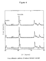
Figure 4 shows X-ray diffraction patterns of the insides (polished surfaces prepared by polishing each of the sintered cermets by 1 mm from the surface) of the sintered cermets inFigures 1 and2 . - An example of a rotary tool according to a first embodiment of the present invention will now be described with referring to scanning electron micrographs (SEM) of
Figures 1 and2 and X-ray diffraction patterns ofFigures 3 and4 . - The rotary tool of the present invention is composed of a sintered
cermet 1 that includes ahard phase 2 and abinding phase 3. The hard phase includes a carbide, a nitride, and a carbonitride of at least one ofgroup hard phase 2 includes: a firsthard phase 2a in which a content of Ti is the highest among contents of the at least one ofgroup hard phase 2b having a higher content ratio in the second phase of a content of the at least one ofgroup hard phase 2a. Thebinding phase 3 is mainly composed of at least one of Co and Ni. - In a scanning electron microscopic (SEM) observation of an arbitrary cross section including a surface of the sintered
cermet 1, as shown inFigures 1 and2 , the firsthard phase 2a is observed as a black grain, the secondhard phase 2b is observed as a grayish white grain, and thebinding phase 3 is observed as a white. - According to the first embodiment, as shown in
Figure 1 (A) , asurface region 4 that mainly contains the firsthard phase 2a is present in a thickness range of 1 to 10 µm. Furthermore, as shown inFigure 3 (A) , when an X-ray diffraction measurement is conducted on a surface of the sinteredcermet 1, peaks (diffraction angle 2θ = 60° to 63°) attributable to a (220) plane of thehard phase 2 are detected as two peaks of a peak on a low-angle side ((1) ofFigure 3 ) and a peak on a high-angle side ((2) ofFigure 3 ), and an intensity ratio of a peak intensity (Ib) of the peak detected on the high-angle side to a peak intensity (Ia) of the peak detected on the low-angle side satisfies Ib/Ia = 0.5 to 1.5. Accordingly, a surface state of the sinteredcermet 1 can be made to be a proper state suitable for use as a rotary tool to provide a rotary tool having high wear resistance and high chipping resistance, and the amount of deformation of the sinteredcermet 1 due to firing can be reduced to provide a rotary tool having a high machining accuracy. The thickness of thesurface region 4 is preferably in the range of 3 to 6 µm. The Ib/Ia ratio in thesurface region 4 is preferably in the range of 0.5 to 1.0 and particularly preferably in the range of 0.7 to 0.95. - Considering the mass of elements and the atomic radius, it is assumed that, out of the peaks attributable to the (220) plane in the X-ray diffraction measurement, the peak on the high-angle side corresponds to the first
hard phase 2a and the peak on the low-angle side corresponds to the secondhard phase 2b. In addition, in the case where the X-ray diffraction measurement is conducted in the inside of thesintered cermet 1, as shown inFigure 4 (A') to (C'), the ratio of the peak on the high-angle side ((2) ofFigure 4 ) to the peak on the low-angle side ((1) ofFigure 4 ) attributable to the (220) plane of thehard phase 2 is substantially the same among samples ofFigure 1 (A') to (C') (sintered cermets of No. I-2, No. I-7, and No. I-5 of Examples described below). The Ib/Ia ratio in aninner part 6 is preferably in the range of 0.4 to 0.6 from the standpoint of wear resistance and suppression of deformation due to firing. - From the standpoint of improving thermal shock resistance, a
top surface layer 5 formed by exudation of thebinding phase 3 on the surface and having a high concentration of thebinding phase 3 is preferably present on the surface of thesurface region 4 of the sinteredcermet 1. Thetop surface layer 5 may cover the entire portion of thesurface region 4 of the sinteredcermet 1 or may partially cover a portion of thesurface region 4. - Furthermore, according to the present invention, the total content of the nitride or the carbonitride of at least one of
group sintered cermet 1 is preferably 70% to 96% by mass, and particularly preferably 85% to 96% by mass from the standpoint of improving wear resistance. In addition, the content of Ti in the nitride or the carbonitride of the at least one ofgroup sintered cermet 1. On the other hand, the content of thebinding phase 3 is preferably 4% to 30% by mass and particularly preferably 10% to 15% by mass, thereby achieving a good balance between the hardness and the toughness of the sinteredcermet 1. A specific composition of the sinteredcermet 1 preferably contains 5% to 15% by mass of Co, 2% to 10% by mass of Ni, 40% to 70% by mass of TiCN, 5% to 30% by mass of WC, 5% to 30% by mass of NbC, 1.0% to 3.0% by mass of VC, 0% to 5% by mass of MoC, 0% to 10% by mass of TaC, and 0% to 3.0% by mass of ZrC. In this case, both wear resistance and chipping resistance of thesintered cermet 1 can be achieved. - The X-ray diffraction measurement in the present invention is first conducted on a surface of the
sintered cermet 1 under the measurement conditions of a radiation source of CuKα (Kα2 is removed), a spot diameter of 100 µm or less, an output of 40 kV and 40 mA, a step of 0.016°, and measurement peaks of a TiN (220) crystal plane (detected at a diffraction angle 2θ of about 60° to 65°). In the case where an X-ray diffraction measurement is subsequently conducted in the inside of thesintered cermet 1, the measurement is conducted on a polished surface prepared by polishing thesintered cermet 1 by 0.5 mm or more from the surface of thesintered cermet 1. - Regarding the average grain size of the
hard phase 2, in the observation of a cross section in the inside of thesintered cermet 1, the average grain size of the firsthard phase 2a is preferably in the range of 0.3 to 0.7 µm, and the average grain size of the secondhard phase 2b is preferably in the range of 0.8 to 1.5 µm from the standpoint that the toughness can be increased. The grain size of the hard phase in the present invention is measured in accordance with the method for measuring an average grain size of cemented carbide specified in CIS-019D-2005. In this measurement, in the case where a grain of thehard phase 2 has a core-rim structure including a core composed of the firsthard phase 2a and a peripheral part surrounding the core and composed of the secondhard phase 2b, the grain size of the firsthard phase 2a of the grain is calculated as the grain size of the firsthard phase 2a itself, and the grain size of the secondhard phase 2b of the grain is calculated on the assumption that an area including the firsthard phase 2a that constitutes the core part and the secondhard phase 2b that constitutes the peripheral part and extending to the outer edge of the peripheral part is considered to be a singlehard phase 2. - From the standpoint of improving plastic deformation resistance, an
intermediate region 7 having an average grain size of thehard phase 2 larger than that of theinner part 6 is preferably present between thesurface region 4 shown inFigure 1 (A) and theinner part 6 shown inFigure 1 (A') with a thickness of 10 to 200 µm. Regarding the average grain size of thehard phase 2 in the observation of a cross section of theintermediate region 7, the average grain size of the firsthard phase 2a is preferably in the range of 0.5 to 1.0 µm, and the average grain size of the secondhard phase 2b is preferably in the range of 1.0 to 2.5 µm. - Furthermore, a residual stress in a σ11 direction of the
sintered cermet 1 measured by a 2D method is preferably a compressive stress of 150 MPa or more in the secondhard phase 2b in the inside of thesintered cermet 1 and a compressive stress of 10 MPa or less in the secondhard phase 2b in a surface portion of thesintered cermet 1. In this case, propagation of cracks formed on the surface can be effectively suppressed, and good chipping resistance can be obtained. Furthermore, since the residual stress hardly acts on the surface portion of thesintered cermet 1, deformation of thesintered cermet 1 is small and thesintered cermet 1 can also be applied to a rotary tool having a complicated shape. - In the present invention, a known hard film composed of TiN, TiCN, TiAlN, or Al2O3 may be deposited as a coating layer (not shown) on the surface of the sintered cermet by a known method for forming a thin film, e.g., physical vapor deposition (PVD) or chemical vapor deposition (CVD).
- The tool of the present invention can be applied to throw-away tip-type turning tools, grooving tools, screw cutting tools, end mills, drills, solid end mills, solid drills, and the like.
- An example of a rotary tool according to a second embodiment of the present invention will now be described. A description of the same configuration as that of the rotary tool of the first embodiment is omitted.
- According to this embodiment, regarding a peak (denoted by Co (200) in the Figures) attributable to a (200) plane of the
binding phase 3 in an X-ray diffraction pattern of thesintered cermet 1 described above, in (A) ofFigures 2 and3 , a ratio ws/wi of a half-width ws of the peak attributable to a (200) plane of thebinding phase 3 on the surface of thesintered cermet 1 to a half-width wi of the peak attributable to the (200) plane of thebinding phase 3 in the inside of thesintered cermet 1 is 1.1 to 1.7. It was found that when the ratio is within this range, thermal shock resistance on the surface of thesintered cermet 1 is improved. The ratio ws/wi is preferably in the range of 1.2 to 1.5. - Here, when the peak of the
binding phase 3 on the surface of thesintered cermet 1 was shifted, by 0.3 to 1.0 degree, to the high-angle side relative to the peak of thebinding phase 3 inside the surface of thesintered cermet 1, deformation of thesintered cermet 1 due to firing was smaller. The amount of peak shift is preferably in the range of 0.4 to 0.6 degrees. - From the standpoint that wear resistance of the
sintered cermet 1 can be increased while reducing deformation of thesintered cermet 1, preferably, thetop surface layer 5 formed by exudation of thebinding phase 3 on the surface is formed such that when an X-ray diffraction measurement is conducted on the surface of thesintered cermet 1, a ratio Ic/(Ia + Ib) of a peak intensity Ic of the peak of thebinding phase 3 to the sum Ia + Ib of the peak intensity Ia of the peak on the low-angle side of thehard phase 2 and the peak intensity Ib of the peak on the high-angle side of thehard phase 2 is 0.5 to 1.4. - Next, an example of a method for producing the sintered cermet of the first embodiment will be described.
- First, a mixed powder is prepared by mixing a TiCN powder having an average particle diameter of 0.6 to 1.0 µm preferably 0.8 to 1.0 µm, at least one powder of a carbide, nitride, or carbonitride of aforementioned other metals of
groups - Next, a wax is added to the mixed powder, and granules having an average diameter of 10 to 200 µm are then prepared by a spray dryer method or the like. The granules are molded into a predetermined shape by press molding. In this step, when the average diameter of the granules is less than 10 µm, the compact has an uneven density, the amount of deformation during firing increases, and the specified surface region is not formed. On the other hand, when the average diameter of the granules exceeds 200 µm, adjacent uncrushed granules tend to remain in the compact, which may result in the formation of defects (voids), and the Ib/Ia ratio exceeds 1.5.
- Next, according to this embodiment, a sintered cermet having the above-described specified structure can be prepared by firing the compact under the conditions below. The firing is conducted under the condition of: (a) increasing the temperature to 1,050°C to 1,250°C at a temperature-increasing rate of 5 to 15 °C/min; (b) increasing the temperature to 1,330°C to 1,380°C at a temperature-increasing rate of 0.1 to 2 °C/min in an atmosphere filled with 30 to 1,500 Pa of nitrogen (N); (c) increasing the temperature to 1,400°C to 1,500°C at a temperature-increasing rate of 4 to 15 °C/min in an atmosphere filled with 30 to 1,500 Pa of nitrogen (N), and maintaining this state for 0.5 to 1.0 hour; (d) increasing the temperature to a high temperature of 1,550°C to 1,600°C at a temperature-increasing rate of 4 to 15 °C/min in a nitrogen atmosphere, and maintaining the maximum temperature for 0.5 to 1.0 hour in a vacuum atmosphere; and then (e) conducting cooling at a cooling rate of 6 to 15 °C/min in an inert gas atmosphere.
- In this method, if step (c) is conducted in a vacuum atmosphere, the formation of a solid solution in the hard phase excessively proceeds, and the surface region of the sintered cermet is not formed. If step (c) is conducted in an atmosphere at a nitrogen pressure of more than 1,500 Pa, the formation of a solid solution in the hard phase is excessively suppressed, and the surface region of the sintered cermet is not formed. If the temperature-increasing rate in step (d) is less than 4 °C/min, solid solution of
group sintered cermet 2, and the (220) peaks in the X-ray diffraction pattern of the surface of the sintered cermet cannot be controlled to be in the specified range. If the temperature-increasing rate is more than 15 °C/min, solid solution ofgroup - Next, a coating layer is deposited on the surface of the tip, as required. Physical vapor deposition (PVD) such as ion plating or sputtering can be suitably employed as the method for depositing the coating layer.
- Next, a method for producing a cermet according to the second embodiment of the present invention will be described. A description of the same conditions as those of the first embodiment is omitted. A sintered cermet of the second embodiment can be prepared by firing a compact produced as in the first embodiment under the conditions below. The firing is conducted under the condition of: (a) increasing the temperature to 1,050°C to 1,250°C at a temperature-increasing rate of 5 to 15 °C/min; (b) increasing the temperature to 1,330°C to 1,380°C at a temperature-increasing rate of 0.1 to 2 °C/min in a vacuum atmosphere; (c) increasing the temperature to 1,500°C to 1,600°C at a temperature-increasing rate of 5 to 10 °C/min in an atmosphere filled with nitrogen (N) at a pressure of 30 to 500 Pa; (d) changing the atmosphere to an atmosphere filled with nitrogen (N) at a pressure higher than the nitrogen pressure in step (c) above and 1,500 Pa or less, and maintaining this state for 0.5 to 1.0 hour; (e) changing again the atmosphere from the nitrogen atmosphere to a vacuum atmosphere, and maintaining this state for 0.5 to 1.0 hour; and then (f) conducting cooling to 1,000°C to 1,100°C in a vacuum atmosphere at a cooling rate of 5 to 10 °C/min, and then conducting cooling in an inert gas atmosphere at a cooling rate of 5 to 15 °C/min.
- In this method, if step (c) is conducted in a vacuum atmosphere, the formation of a solid solution in the hard phase excessively proceeds, and the surface region of the sintered cermet is not formed. If step (c) is conducted in an atmosphere at a nitrogen pressure of more than 500 Pa, the formation of a solid solution in the hard phase is excessively suppressed, and the surface region of the sintered cermet is not formed. If the nitrogen pressure in the atmosphere in step (c) is the same as the nitrogen pressure in the atmosphere in step (d), the Ib/la ratio exceeds 1.5. If the temperature-increasing rate in step (c) is less than 5 °C/min, solid solution of
group sintered cermet 2, and the (220) peaks in the X-ray diffraction pattern of the surface of the sintered cermet cannot be controlled to be in the specified range. If the temperature-increasing rate is more than 10 °C/min, solid solution ofgroup - A mixed powder was prepared by mixing a TiCN powder having an average particle diameter (d50 value) of 0.6 µm, a WC powder having an average particle diameter of 1.1 µm, a TiN powder having an average particle diameter of 1.5 µm, a VC powder having an average particle diameter of 1.0 µm, a TaC powder having an average particle diameter of 2 µm, a MoC powder having an average particle diameter of 1.5 µm, a NbC powder having an average particle diameter of 1.5 µm, a ZrC powder having an average particle diameter of 1.8 µm, a Ni powder having an average particle diameter of 2.4 µm, a Co powder having an average particle diameter of 1.9 µm, and a MnCO3 powder having an average particle diameter of 5.0 µm in a mixing ratio shown in Table 1. All of these average particle diameters were measured by a micro-track method. Isopropyl alcohol (IPA) was added to the mixed powder, and wet mixing was conducted using a stainless steel ball mill and cemented carbide balls. Furthermore, 3% by mass of paraffin was added thereto and mixed. The resulting mixture was charged in an attritor mill, and granules having an average diameter shown in Table 1 were prepared by spray drying.
- Subsequently, the granules were press-molded into the shape of a throw-away tip tool of CERATIP, Model No. BDMT11T308ER-JT, manufactured by KYOCERA Corporation by applying a pressure of 200 MPa. In step (a), the temperature was increased to 1,200°C at a temperature-increasing rate of 10 °C/min. In step (b), the temperature was increased to 1,350°C at a temperature-increasing rate of 1 °C/min. Subsequently, firing was conducted under the firing conditions shown in Table 2. In step (e), cooling was conducted in a nitrogen gas atmosphere at a cooling rate of 10 °C/min. Thus, cermet throw-away tips of sample Nos. I-1 to I-8 were obtained.
Table 1 Sample No. Raw material composition (mass%) Average diameter of granules (µm) TiCN TiN WC TaC MoC NbC ZrC VC Ni Co MnCO3 I- 1 Balance - 8 - 5 6 1 - 4 6 - 120 I- 2 Balance 6 10 6 4 4 0.2 1.5 5 7.5 1.0 90 I- 3 Balance 7 12 5 - 5 - 2.5 5 10 1.5 160 I- 4 Balance 10 10 4 5 - 0.1 1 3 9 - 50 I- 5 Balance 7 12 1 0 5 0.2 2.4 4 8 1 120 I- 6 Balance 8 6 2 5 10 0.5 0 6 7 0 80 I- 7 Balance 12 10 2 0 7 0.2 2 4 8 1 30 I- 8 Balance 5 11 5 2 9 0.3 1.3 6 7 0.5 250 Table 2 Sample No. Step (c) Step (d) Atmosphere during temperature increasing Temperature Increasing Rate (°C/min) Firing Temperature (°C) Firing time (h) Atmosphere during temperature increasing Temperature Increasing Rate (°C/min) Firing Temperature (°C) Firing time (h) Atmosphere Pressure (Pa) Atmosphere Pressure (Pa) I- 1 N2 1500 10 1400 0.5 N2 700 6 1600 1 I- 2 N2 1000 7 1500 0.5 N2 1000 7 1575 0.5 I- 3 N2 500 8 1450 0.5 N2 1500 5 1575 0.5 I- 4 N2 100 12 1500 1 N2 100 15 1550 0.8 I- 5 Vacuum 5 1500 0.5 Vacuum 5 1600 1 I- 6 N2 800 7 1550 1 N2 800 3.5 1600 1 I- 7 N2 1800 7 1500 0.5 N2 1800 10 1550 0.5 I- 8 N2 800 7 1450 0.5 N2 1000 8 1500 0.6 Table 3 Sample No. SEM observation XRD peak Top surface layer Thickness of surface region (µm) Intermediate region Inner part Ib/Ia First hard phase Second hard phase First hard phase Second hard phase Surface region Inside I- 1 Not formed 2 1.0 2.3 0.8 1.2 0.52 0.42 I- 2 Formed 6 0.8 1.5 0.7 1.0 0.82 0.47 I- 3 Formed 5 0.7 1.4 0.8 1.1 0.92 0.53 I- 4 Formed 10 0.6 1.0 0.6 0.9 1.29 0.60 I- 5 Not formed Not formed 1.1 2.5 0.8 1.1 0.16 0.35 I- 6 Not formed Not formed 1.2 2.7 0.7 1.2 0.20 0.45 I- 7 Formed 6 0.7 1.3 0.7 1.1 2.86 0.34 I- 8 Formed 12 0.6 1.2 0.6 0.9 1.90 0.39 1) SEM observation: Regarding the intermediate region and the inner part, the average grain sizes (µm) of the hard phases are shown. Table 4 Sample No. Residual stress (MPa) Cutting performance Surface region Inside Perpendicularity (µm) Wear resistance (min) Chipping resistance (mm) I- 1 -10 -160 38 34 1360 I- 2 5 -230 35 37 1590 I- 3 20 -200 41 34 1520 I- 4 10 -180 32 30 1480 I- 5 -110 -30 62 35 1040 I- 6 -170 -100 70 31 1080 I- 7 120 -80 44 23 1150 I- 8 100 -50 43 28 920 - A flank face of each of the prepared sintered cermets was ground away 0.5 mm in a thickness direction to form a mirror surface. An X-ray diffraction analysis was then conducted under the conditions of a measurement range of 2θ = 50° to 80° including 60° to 63°, with a radiation source of CuKα ray (Kα1 was removed), and using a crystal phase of TiCN (220) in the analysis. Thus, diffraction patterns of
Figures 2 and3 were obtained. As shown inFigure 3 , the X-ray diffraction patterns in the insides of the sintered cermets were substantially the same among No. I-2, No. I-7, and No. I-5. In contrast, as shown inFigure 2 , regarding the X-ray diffraction patterns on the surfaces of the sintered cermets, the peak intensities of two peaks attributable to the (220) plane of the hard phase were different among the samples. This peak intensity ratio of each sample was calculated. The results are shown in Table 3. Furthermore, a scanning electron micrograph was taken on a cross section including a surface of each sintered cermet, and a structure observation as shown inFigure 1 was conducted. The states of structures of the top surface layer, the surface region, the intermediate region, and the inner part are shown in Table 3. - Next, for each of the prepared sintered cermets, in each of the surface region on a mirror surface prepared by grinding away 0.5 mm of a rake face in a thickness direction and an inner portion prepared by polishing away 1 mm from the rake face, a residual stress of the second hard phase was measured by a 2D method (apparatus: X-ray diffractometer, D8 DISCOVER with GADDS Super Speed, manufactured by Bruker AXS K.K., radiation source: CuKα, collimator diameter: 0.3 mmφ, measured diffraction line: TiN (422) plane). Furthermore, a cutting test was conducted using the prepared cermet cutting tools under the cutting conditions described below. These results are shown in Table 4.
-
- Work material: SKD11
- Cutting speed: 120 m/min
- Feed: 0.12 mm/tooth
- Cutting depth: 2.0 mm
- Cutting condition: Dry method
- Evaluation parameters: The time until the amount of wear reaches 0.2 mm, and the average (µm) of the perpendicularity of two corner cutting edges.
-
- Work material: SCM440H
- Cutting speed: 150 m/min
- Feed: 0.15 mm/tooth
- Cutting depth: 3.0 mm
- Cutting condition: Dry method
- Evaluation parameter: The length (mm) of cut until chipping occurs
- As shown in Tables 1 to 4, in each of sample No. I-5, in which the atmosphere in steps (c) and (d) was a vacuum atmosphere, and sample No. I-6, in which the firing temperature in step (c) was higher than 1,500°C, the surface region was not formed, chipping resistance decreased, and deformation of the sintered cermet was large and thus the dimensional accuracy such as perpendicularity in machining was low. In each of sample No. I-7, in which the gas pressure exceeded 1,500 Pa, and sample No. I-8, in which the average diameter of the granules for preparing the compact was more than 200 µm, the Ib/Ia ratio in the X-ray diffraction peaks of the sintered cermet exceeded 1.5 and wear resistance decreased.
- In contrast, sample Nos. I-1 to I-4 each having the structure and the X-ray diffraction pattern within the ranges of the present invention exhibited good wear resistance and chipping resistance and had a good tool life.
- Compacts shown in Table 5 were prepared using the same method, materials, and additives as those used in Example 1. In step (a), the temperature was increased to 1,200°C at a temperature-increasing rate of 10 °C/min. In step (b), the temperature was increased to 1,350°C at a temperature-increasing rate of 1 °C/min. Subsequently, firing was conducted under the firing conditions shown in Table 6. Next, in step (f), cooling was conducted in a nitrogen gas atmosphere at a cooling rate of 10 °C/min. Thus, cermet throw-away tips of sample Nos. II-1 to II-9 were obtained.
Table 5 Sample No. Raw material composition (mass%) Average diameter of granules (mm) TiCN TiN WC TaC MoC NbC ZrC VC Ni Co MnCO3 II- 1 Balance - 11 - 5 6 1 - 4 6 - 120 II- 2 Balance 6 10 8 6 4 0.2 1.5 6 7 1.0 90 II- 3 Balance 7 12 3 - 8 - 2.5 5 10 1.5 160 II- 4 Balance 10 10 4 5 - 0.1 1 3 9 - 50 II- 5 Balance 9 15 1 0 10 0.2 2.4 4 8 1 120 II- 6 Balance 8 6 2 5 10 0.5 0 6 7 0 80 II- 7 Balance 12 10 2 0 7 0.2 2 4 8 1 30 II- 8 Balance 10 11 5 2 9 0.3 1.3 6 7 0.5 250 II- 9 Balance 10 10 4 5 - 0.1 1 3 9 - 50 Table 6 Sample No. Step (c) Step (d) Step (e) Atmosphere during temperature increasing Temperature Increasing Rate (°C/min) Firing Temperature (°C) Atmosphere during temperature increasing Holding Temperature (°C) Firing time (h) Atmosphere Pressure (Pa) Atmosphere Pressure (Pa) II- 1 N2 100 6 1525 N2 700 0.3 1 II- 2 N2 500 7 1575 N2 1000 0.5 0.5 II- 3 N2 500 5 1575 N2 1500 0.5 0.5 II- 4 N2 100 10 1550 N2 1000 0.5 0.8 II- 5 Vacuum 5 5 Vacuum 0.5 0.5 II- 6 N2 400 3.5 1600 N2 800 1 1 II- 7 N2 1800 10 1575 N2 1800 0.5 0.5 II- 8 N2 500 8 1550 N2 1000 0.5 0.6 II- 9 N2 100 15 1550 N2 100 1 0.8 Table 7 Sample No. SEM observation XRD peak Top surface layer Thickness of surface region (µm) Intermediate region Inner part Ib/Ia peak of binding phase Ic/(Ia+Ib) First hard phase Second hard phase First hard phase Second hard phase Surface region Inside Peak shift ws/wi II- 1 Formed 2 0.8 1.8 0.8 1.2 0.90 0.42 0.45 1.18 1.14 II- 2 Formed 4 0.8 1.5 0.6 1.0 0.81 0.47 0.51 1.33 0.85 II- 3 Formed 5 0.7 1.3 0.8 1.0 0.97 0.52 0.28 1.11 0.79 II- 4 Not formed 8 1 2.1 0.5 0.9 0.85 0.60 0.73 1.47 0.53 II- 5 Not formed Not formed 1.1 2.1 0.6 1.1 0.14 0.33 0.23 1.08 0.21 II- 6 Not formed Not formed 1.3 2.9 0.7 1.2 0.35 0.44 0.16 1.18 0.30 II- 7 Formed 6 0.7 1.3 0.6 1.1 2.86 0.34 0.62 0.70 1.52 II- 8 Formed 10 0.5 1.1 0.6 1.0 1.65 0.38 0.44 0.90 0.67 II- 9 Formed 10 0.6 1.0 0.5 0.9 1.29 0.60 0.54 0.96 1.52 1) SEM observation: Regarding the intermediate region and the inner part, the average grain sizes (µ m) of the hard phases are shown. Table 8 Sample No. Residual stress (MPa) Cutting performance Surface region Inside Perpendicularity (µm) Wear resistance (min) Chipping resistance (mm) II- 1 10 -200 32 41 1680 II- 2 5 -210 35 45 1800 II- 3 20 -160 42 33 1510 II- 4 -10 -180 38 40 1590 II- 5 -150 -5 60 29 1020 II- 6 -160 -10 71 32 1090 II- 7 150 -80 44 23 1150 II- 8 120 -50 37 26 980 II- 9 -10 -100 32 30 1480 - For each of the prepared sintered cermets, the peak intensity ratio, the states of structures of the top surface layer, the surface region, the intermediate region, and the inner part were examined as same as Example 1. The results are shown in Table 7. The residual stresses of the sintered cermets were measured. The results are shown in Table.
- 8. Furthermore, a cutting test was conducted using the cermet cutting tools under the same cutting conditions as Example 1. The results are also shown in Table 8.
- As shown in Tables 5 to 8, in each of sample No. II-5, in which the atmosphere in steps (c) and (d) was a vacuum atmosphere, and sample No. II-6, in which the firing temperature in step (c) was higher than 1,500°C, the surface region was not formed, chipping resistance decreased, and deformation of the sintered cermet was large and thus the dimensional accuracy such as perpendicularity in machining was low. In each of sample No. II-7, in which the gas pressure exceeded 1,500 Pa, and sample No. II-8, in which the average diameter of the granules for preparing the compact was more than 200 µm, the Ib/Ia ratio in the X-ray diffraction peaks of the sintered cermet exceeded 1.5 and wear resistance decreased. Furthermore, in sample No. II-9, in which the nitrogen gas pressure in step (d) was the same as the nitrogen gas pressure in step (c), the ratio (ws/wi) was smaller than 1.1 and chipping resistance was low.
- In contrast, sample Nos. II-1 to II-4 each having the structure and the X-ray diffraction pattern within the ranges of the present invention and having a ratio (ws/wi) of 1.1 to 1.7 exhibited good wear resistance and chipping resistance and had a good tool life.
-
- 1
- sintered cermet
- 2
- hard phase
2a first hard phase
2b second hard phase - 3
- binding phase
- 4
- surface region
- 5
- top surface layer
- 6
- inner part
- 7
- intermediate region
Claims (8)
- A rotary tool, composed of a sintered cermet,
wherein the sintered cermet comprises:a hard phase comprising a carbide, a nitride, and a carbonitride of at least one of group 4, 5, and 6 metals of the periodic table of which titanium is a main component; anda binding phase mainly composed of at least one of Co and Ni, wherein the hard phase further comprises:wherein the sintered cermet further comprises a surface region that mainly includes the first hard phase is present in a thickness range of 1 to 10 µm in a scanning electron microscopic observation of an arbitrary cross section including a surface of the sintered cermet, anda first hard phase in which a content of Ti is the highest among contents of the at least one of group 4, 5, and 6 metals of the periodic table; anda second hard phase having a higher content ratio of a content of the at least one of group 4, 5, and 6 metals of the periodic table other than Ti than the content ratio in the first hard phase,
wherein, when an X-ray diffraction measurement is conducted on a surface of the sintered cermet, peaks attributable to a (220) plane of the hard phase are detected as two peaks on the low-angle side and on the high-angle side, and an intensity ratio of a peak intensity (Ib) of the peak on the high-angle side to a peak intensity (Ia) of the peak on the low-angle side satisfies Ib/Ia = 0.5 to 1.5. - The rotary tool according to claim 1, wherein a top surface layer having a high concentration of the binding phase is present on the surface of the sintered cermet.
- A rotary tool, composed of a sintered cermet,
wherein the sintered cermet comprises:a hard phase comprising a carbide, a nitride, and a carbonitride of at least one of group 4, 5, and 6 metals of the periodic table of which titanium is a main component; anda binding phase mainly composed of at least one of Co and Ni, andwherein the hard phase further comprises:a first hard phase in which a content of Ti is the highest among contents of the at least one of group 4, 5, and 6 metals of the periodic table; anda second hard phase having a higher content ratio of a content of the at least one of group 4, 5, and 6 metals of the periodic table other than Ti than the content ratio in the first hard phase,wherein, when an X-ray diffraction measurement is conducted on a surface of the sintered cermet,
peaks attributable to a (220) plane of the hard phase are detected as two peaks on the low-angle side and on the high-angle side, and
an intensity ratio Ib/Ia of a peak intensity Ib of the peak on the high-angle side to a peak intensity la of the peak on the low-angle side is 0.5 to 1.5, and
a ratio (ws/wi) of a half-width ws of a peak attributable to a (200) plane of the binding phase on the surface of the sintered cermet to a half-width wi of the peak of the binding phase in the inside of the sintered cermet is 1.1 to 1.7. - The rotary tool according to claim 3, wherein the peak of the binding phase on the surface of the sintered cermet is shifted, by 0.3 to 1.0 degree, to the high-angle side relative to the peak of the binding phase in the inside of the sintered cermet.
- The rotary tool according to claim 3 or 4, wherein a surface region that mainly comprises the first hard phase is present in a thickness range of 1 to 10 µm in a scanning electron microscopic observation of an arbitrary cross section including a surface of the sintered cermet.
- The rotary tool according to claim 5, wherein a top surface layer comprising a high concentration of the binding phase is present on the surface of the surface region.
- The rotary tool according to claim 6, wherein a ratio Ic/(Ia + Ib) of a peak intensity Ic of the peak of the binding phase to the sum Ia + Ib of the peak intensity Ia of the peak on the low-angle side and the peak intensity Ib of the peak on the high-angle side of the hard phase is 0.5 to 1.4 when an X-ray diffraction measurement is conducted on a surface of the sintered cermet.
- The rotary tool according to any one of claims 1 to 7, wherein a residual stress in a σ11 direction of the sintered cermet measured by a 2D method is a compressive stress of 150 MPa or more in the second hard phase in the inside of the sintered cermet and a compressive stress of 10 MPa or less in the second hard phase in a surface portion of the sintered cermet.
Applications Claiming Priority (3)
| Application Number | Priority Date | Filing Date | Title |
|---|---|---|---|
| JP2009268218 | 2009-11-26 | ||
| JP2010012657 | 2010-01-23 | ||
| PCT/JP2010/071099 WO2011065468A1 (en) | 2009-11-26 | 2010-11-26 | Rotation tool |
Publications (3)
| Publication Number | Publication Date |
|---|---|
| EP2505289A1 true EP2505289A1 (en) | 2012-10-03 |
| EP2505289A4 EP2505289A4 (en) | 2017-08-02 |
| EP2505289B1 EP2505289B1 (en) | 2019-06-05 |
Family
ID=44066572
Family Applications (1)
| Application Number | Title | Priority Date | Filing Date |
|---|---|---|---|
| EP10833314.7A Active EP2505289B1 (en) | 2009-11-26 | 2010-11-26 | Rotation tool |
Country Status (5)
| Country | Link |
|---|---|
| US (1) | US8808871B2 (en) |
| EP (1) | EP2505289B1 (en) |
| JP (1) | JP5355712B2 (en) |
| CN (1) | CN102574223B (en) |
| WO (1) | WO2011065468A1 (en) |
Families Citing this family (5)
| Publication number | Priority date | Publication date | Assignee | Title |
|---|---|---|---|---|
| JP6172382B2 (en) * | 2014-03-19 | 2017-08-02 | 株式会社タンガロイ | Cermet tool |
| JP6380016B2 (en) * | 2014-11-05 | 2018-08-29 | 株式会社タンガロイ | Cermet tools and coated cermet tools |
| CN109975339B (en) * | 2017-12-28 | 2023-08-15 | 厦门钨业股份有限公司 | Evaluation method for TiCN-based cermet performance |
| CN114787399A (en) * | 2019-12-19 | 2022-07-22 | 山特维克科洛曼特公司 | Gradient cemented carbide with alternative binder |
| US12319991B2 (en) | 2020-05-26 | 2025-06-03 | Sumitomo Electric Industries, Ltd. | Base material and cutting tool |
Family Cites Families (9)
| Publication number | Priority date | Publication date | Assignee | Title |
|---|---|---|---|---|
| JP3217404B2 (en) | 1991-10-04 | 2001-10-09 | 日本特殊陶業株式会社 | Cermet for rotary tools |
| JP3078427B2 (en) * | 1993-07-29 | 2000-08-21 | 京セラ株式会社 | Cermet for cutting tools |
| JPH0813077A (en) * | 1994-07-05 | 1996-01-16 | Sumitomo Electric Ind Ltd | Nitrogen-containing sintered hard alloy |
| JP2737676B2 (en) * | 1994-12-27 | 1998-04-08 | 住友電気工業株式会社 | Nitrogen-containing sintered hard alloy |
| JP5098382B2 (en) | 2007-03-14 | 2012-12-12 | セイコーエプソン株式会社 | Electronic clock with power generation function |
| EP2177639B1 (en) | 2007-07-27 | 2020-03-04 | Kyocera Corporation | Titanium-base cermet, coated cermet, and cutting tool |
| JP5273987B2 (en) * | 2007-10-26 | 2013-08-28 | 京セラ株式会社 | Cermet manufacturing method |
| JP5393044B2 (en) * | 2008-03-25 | 2014-01-22 | 京セラ株式会社 | cermet |
| EP2332678B1 (en) * | 2008-09-26 | 2019-06-12 | Kyocera Corporation | Sintered cermet and cutting tool |
-
2010
- 2010-11-26 WO PCT/JP2010/071099 patent/WO2011065468A1/en not_active Ceased
- 2010-11-26 US US13/512,301 patent/US8808871B2/en active Active
- 2010-11-26 JP JP2011543313A patent/JP5355712B2/en active Active
- 2010-11-26 EP EP10833314.7A patent/EP2505289B1/en active Active
- 2010-11-26 CN CN201080047205.5A patent/CN102574223B/en active Active
Non-Patent Citations (1)
| Title |
|---|
| See references of WO2011065468A1 * |
Also Published As
| Publication number | Publication date |
|---|---|
| JP5355712B2 (en) | 2013-11-27 |
| CN102574223B (en) | 2014-01-29 |
| WO2011065468A1 (en) | 2011-06-03 |
| JPWO2011065468A1 (en) | 2013-04-18 |
| US8808871B2 (en) | 2014-08-19 |
| CN102574223A (en) | 2012-07-11 |
| EP2505289B1 (en) | 2019-06-05 |
| EP2505289A4 (en) | 2017-08-02 |
| US20120263944A1 (en) | 2012-10-18 |
Similar Documents
| Publication | Publication Date | Title |
|---|---|---|
| JP6677932B2 (en) | Surface coated cutting tool that demonstrates excellent chipping and wear resistance in heavy interrupted cutting | |
| EP2778146B1 (en) | Cubic boron nitride sintered body | |
| EP2332678B1 (en) | Sintered cermet and cutting tool | |
| EP2656948B1 (en) | Cutting tool | |
| EP2474634A1 (en) | Super hard alloy and cutting tool using same | |
| KR20140138772A (en) | Surface-coated cutting tool having therein hard coating layer capable of exhibiting excellent chipping resistance during high-speed intermittent cutting work | |
| EP1892051A1 (en) | Cermet insert and cutting tool | |
| US20110129312A1 (en) | Cutting Tool | |
| EP3412386A1 (en) | Surface-coated cutting tool and manufacturing method therefor | |
| EP1535680B1 (en) | Coated cutting tool member | |
| EP2505289B1 (en) | Rotation tool | |
| JP2001310203A (en) | Surface-coated cemented carbide cutting tool with excellent surface lubricity to chips | |
| JP5559575B2 (en) | Cermet and coated cermet | |
| CN108698135B (en) | Cutting insert | |
| JP7385829B2 (en) | WC-based cemented carbide cutting tools and surface-coated WC-based cemented carbide cutting tools with excellent plastic deformation resistance and fracture resistance | |
| JP3931325B2 (en) | Surface coated cemented carbide cutting tool with excellent wear resistance with hard coating layer in high speed cutting | |
| JP3844285B2 (en) | Surface-coated cemented carbide cutting tool with excellent wear resistance due to high-speed cutting and hard coating layer | |
| JP3829322B2 (en) | Surface coated cemented carbide cutting tool with excellent adhesion and chipping resistance with wear resistant coating layer | |
| EP1470880B1 (en) | Coated cutting tool member having hard coating layer and method for forming the hard coating layer on cutting tool | |
| JP5213644B2 (en) | Cermet sintered body and cutting tool | |
| JP7441420B2 (en) | Cutting tools that exhibit excellent fracture resistance and plastic deformation resistance | |
| KR102574445B1 (en) | Cermet, manufacturing method thereof and cutting tool | |
| JP7748024B2 (en) | sintered cermet | |
| JP2001162411A (en) | Surface-coated cemented carbide cutting tool with excellent wear and chipping resistance | |
| JP4748361B2 (en) | Surface-coated cermet cutting tool with excellent chipping resistance with hard coating layer in difficult-to-cut materials |
Legal Events
| Date | Code | Title | Description |
|---|---|---|---|
| PUAI | Public reference made under article 153(3) epc to a published international application that has entered the european phase |
Free format text: ORIGINAL CODE: 0009012 |
|
| 17P | Request for examination filed |
Effective date: 20120614 |
|
| AK | Designated contracting states |
Kind code of ref document: A1 Designated state(s): AL AT BE BG CH CY CZ DE DK EE ES FI FR GB GR HR HU IE IS IT LI LT LU LV MC MK MT NL NO PL PT RO RS SE SI SK SM TR |
|
| DAX | Request for extension of the european patent (deleted) | ||
| RA4 | Supplementary search report drawn up and despatched (corrected) |
Effective date: 20170704 |
|
| RIC1 | Information provided on ipc code assigned before grant |
Ipc: C22C 29/02 20060101ALI20170628BHEP Ipc: C22C 29/10 20060101AFI20170628BHEP |
|
| REG | Reference to a national code |
Ref country code: DE Ref legal event code: R079 Ref document number: 602010059304 Country of ref document: DE Free format text: PREVIOUS MAIN CLASS: B23C0005160000 Ipc: C22C0029100000 |
|
| GRAP | Despatch of communication of intention to grant a patent |
Free format text: ORIGINAL CODE: EPIDOSNIGR1 |
|
| STAA | Information on the status of an ep patent application or granted ep patent |
Free format text: STATUS: GRANT OF PATENT IS INTENDED |
|
| RIC1 | Information provided on ipc code assigned before grant |
Ipc: C22C 29/10 20060101AFI20181211BHEP Ipc: B22F 3/10 20060101ALI20181211BHEP Ipc: C22C 29/02 20060101ALI20181211BHEP |
|
| INTG | Intention to grant announced |
Effective date: 20190108 |
|
| GRAS | Grant fee paid |
Free format text: ORIGINAL CODE: EPIDOSNIGR3 |
|
| GRAA | (expected) grant |
Free format text: ORIGINAL CODE: 0009210 |
|
| STAA | Information on the status of an ep patent application or granted ep patent |
Free format text: STATUS: THE PATENT HAS BEEN GRANTED |
|
| AK | Designated contracting states |
Kind code of ref document: B1 Designated state(s): AL AT BE BG CH CY CZ DE DK EE ES FI FR GB GR HR HU IE IS IT LI LT LU LV MC MK MT NL NO PL PT RO RS SE SI SK SM TR |
|
| REG | Reference to a national code |
Ref country code: GB Ref legal event code: FG4D |
|
| REG | Reference to a national code |
Ref country code: CH Ref legal event code: EP |
|
| REG | Reference to a national code |
Ref country code: AT Ref legal event code: REF Ref document number: 1140031 Country of ref document: AT Kind code of ref document: T Effective date: 20190615 |
|
| REG | Reference to a national code |
Ref country code: DE Ref legal event code: R096 Ref document number: 602010059304 Country of ref document: DE |
|
| REG | Reference to a national code |
Ref country code: IE Ref legal event code: FG4D |
|
| REG | Reference to a national code |
Ref country code: NL Ref legal event code: MP Effective date: 20190605 |
|
| REG | Reference to a national code |
Ref country code: LT Ref legal event code: MG4D |
|
| PG25 | Lapsed in a contracting state [announced via postgrant information from national office to epo] |
Ref country code: ES Free format text: LAPSE BECAUSE OF FAILURE TO SUBMIT A TRANSLATION OF THE DESCRIPTION OR TO PAY THE FEE WITHIN THE PRESCRIBED TIME-LIMIT Effective date: 20190605 Ref country code: AL Free format text: LAPSE BECAUSE OF FAILURE TO SUBMIT A TRANSLATION OF THE DESCRIPTION OR TO PAY THE FEE WITHIN THE PRESCRIBED TIME-LIMIT Effective date: 20190605 Ref country code: FI Free format text: LAPSE BECAUSE OF FAILURE TO SUBMIT A TRANSLATION OF THE DESCRIPTION OR TO PAY THE FEE WITHIN THE PRESCRIBED TIME-LIMIT Effective date: 20190605 Ref country code: NO Free format text: LAPSE BECAUSE OF FAILURE TO SUBMIT A TRANSLATION OF THE DESCRIPTION OR TO PAY THE FEE WITHIN THE PRESCRIBED TIME-LIMIT Effective date: 20190905 Ref country code: LT Free format text: LAPSE BECAUSE OF FAILURE TO SUBMIT A TRANSLATION OF THE DESCRIPTION OR TO PAY THE FEE WITHIN THE PRESCRIBED TIME-LIMIT Effective date: 20190605 Ref country code: HR Free format text: LAPSE BECAUSE OF FAILURE TO SUBMIT A TRANSLATION OF THE DESCRIPTION OR TO PAY THE FEE WITHIN THE PRESCRIBED TIME-LIMIT Effective date: 20190605 Ref country code: SE Free format text: LAPSE BECAUSE OF FAILURE TO SUBMIT A TRANSLATION OF THE DESCRIPTION OR TO PAY THE FEE WITHIN THE PRESCRIBED TIME-LIMIT Effective date: 20190605 |
|
| PG25 | Lapsed in a contracting state [announced via postgrant information from national office to epo] |
Ref country code: LV Free format text: LAPSE BECAUSE OF FAILURE TO SUBMIT A TRANSLATION OF THE DESCRIPTION OR TO PAY THE FEE WITHIN THE PRESCRIBED TIME-LIMIT Effective date: 20190605 Ref country code: GR Free format text: LAPSE BECAUSE OF FAILURE TO SUBMIT A TRANSLATION OF THE DESCRIPTION OR TO PAY THE FEE WITHIN THE PRESCRIBED TIME-LIMIT Effective date: 20190906 Ref country code: BG Free format text: LAPSE BECAUSE OF FAILURE TO SUBMIT A TRANSLATION OF THE DESCRIPTION OR TO PAY THE FEE WITHIN THE PRESCRIBED TIME-LIMIT Effective date: 20190905 Ref country code: RS Free format text: LAPSE BECAUSE OF FAILURE TO SUBMIT A TRANSLATION OF THE DESCRIPTION OR TO PAY THE FEE WITHIN THE PRESCRIBED TIME-LIMIT Effective date: 20190605 |
|
| REG | Reference to a national code |
Ref country code: AT Ref legal event code: MK05 Ref document number: 1140031 Country of ref document: AT Kind code of ref document: T Effective date: 20190605 |
|
| PG25 | Lapsed in a contracting state [announced via postgrant information from national office to epo] |
Ref country code: AT Free format text: LAPSE BECAUSE OF FAILURE TO SUBMIT A TRANSLATION OF THE DESCRIPTION OR TO PAY THE FEE WITHIN THE PRESCRIBED TIME-LIMIT Effective date: 20190605 Ref country code: PT Free format text: LAPSE BECAUSE OF FAILURE TO SUBMIT A TRANSLATION OF THE DESCRIPTION OR TO PAY THE FEE WITHIN THE PRESCRIBED TIME-LIMIT Effective date: 20191007 Ref country code: EE Free format text: LAPSE BECAUSE OF FAILURE TO SUBMIT A TRANSLATION OF THE DESCRIPTION OR TO PAY THE FEE WITHIN THE PRESCRIBED TIME-LIMIT Effective date: 20190605 Ref country code: NL Free format text: LAPSE BECAUSE OF FAILURE TO SUBMIT A TRANSLATION OF THE DESCRIPTION OR TO PAY THE FEE WITHIN THE PRESCRIBED TIME-LIMIT Effective date: 20190605 Ref country code: CZ Free format text: LAPSE BECAUSE OF FAILURE TO SUBMIT A TRANSLATION OF THE DESCRIPTION OR TO PAY THE FEE WITHIN THE PRESCRIBED TIME-LIMIT Effective date: 20190605 Ref country code: SK Free format text: LAPSE BECAUSE OF FAILURE TO SUBMIT A TRANSLATION OF THE DESCRIPTION OR TO PAY THE FEE WITHIN THE PRESCRIBED TIME-LIMIT Effective date: 20190605 Ref country code: RO Free format text: LAPSE BECAUSE OF FAILURE TO SUBMIT A TRANSLATION OF THE DESCRIPTION OR TO PAY THE FEE WITHIN THE PRESCRIBED TIME-LIMIT Effective date: 20190605 |
|
| PG25 | Lapsed in a contracting state [announced via postgrant information from national office to epo] |
Ref country code: SM Free format text: LAPSE BECAUSE OF FAILURE TO SUBMIT A TRANSLATION OF THE DESCRIPTION OR TO PAY THE FEE WITHIN THE PRESCRIBED TIME-LIMIT Effective date: 20190605 Ref country code: IS Free format text: LAPSE BECAUSE OF FAILURE TO SUBMIT A TRANSLATION OF THE DESCRIPTION OR TO PAY THE FEE WITHIN THE PRESCRIBED TIME-LIMIT Effective date: 20191005 Ref country code: IT Free format text: LAPSE BECAUSE OF FAILURE TO SUBMIT A TRANSLATION OF THE DESCRIPTION OR TO PAY THE FEE WITHIN THE PRESCRIBED TIME-LIMIT Effective date: 20190605 |
|
| REG | Reference to a national code |
Ref country code: DE Ref legal event code: R097 Ref document number: 602010059304 Country of ref document: DE |
|
| PG25 | Lapsed in a contracting state [announced via postgrant information from national office to epo] |
Ref country code: TR Free format text: LAPSE BECAUSE OF FAILURE TO SUBMIT A TRANSLATION OF THE DESCRIPTION OR TO PAY THE FEE WITHIN THE PRESCRIBED TIME-LIMIT Effective date: 20190605 |
|
| PLBE | No opposition filed within time limit |
Free format text: ORIGINAL CODE: 0009261 |
|
| STAA | Information on the status of an ep patent application or granted ep patent |
Free format text: STATUS: NO OPPOSITION FILED WITHIN TIME LIMIT |
|
| PG25 | Lapsed in a contracting state [announced via postgrant information from national office to epo] |
Ref country code: DK Free format text: LAPSE BECAUSE OF FAILURE TO SUBMIT A TRANSLATION OF THE DESCRIPTION OR TO PAY THE FEE WITHIN THE PRESCRIBED TIME-LIMIT Effective date: 20190605 Ref country code: PL Free format text: LAPSE BECAUSE OF FAILURE TO SUBMIT A TRANSLATION OF THE DESCRIPTION OR TO PAY THE FEE WITHIN THE PRESCRIBED TIME-LIMIT Effective date: 20190605 |
|
| 26N | No opposition filed |
Effective date: 20200306 |
|
| PG25 | Lapsed in a contracting state [announced via postgrant information from national office to epo] |
Ref country code: SI Free format text: LAPSE BECAUSE OF FAILURE TO SUBMIT A TRANSLATION OF THE DESCRIPTION OR TO PAY THE FEE WITHIN THE PRESCRIBED TIME-LIMIT Effective date: 20190605 |
|
| REG | Reference to a national code |
Ref country code: CH Ref legal event code: PL |
|
| PG25 | Lapsed in a contracting state [announced via postgrant information from national office to epo] |
Ref country code: MC Free format text: LAPSE BECAUSE OF FAILURE TO SUBMIT A TRANSLATION OF THE DESCRIPTION OR TO PAY THE FEE WITHIN THE PRESCRIBED TIME-LIMIT Effective date: 20190605 Ref country code: LU Free format text: LAPSE BECAUSE OF NON-PAYMENT OF DUE FEES Effective date: 20191126 Ref country code: LI Free format text: LAPSE BECAUSE OF NON-PAYMENT OF DUE FEES Effective date: 20191130 Ref country code: CH Free format text: LAPSE BECAUSE OF NON-PAYMENT OF DUE FEES Effective date: 20191130 |
|
| REG | Reference to a national code |
Ref country code: BE Ref legal event code: MM Effective date: 20191130 |
|
| GBPC | Gb: european patent ceased through non-payment of renewal fee |
Effective date: 20191126 |
|
| PG25 | Lapsed in a contracting state [announced via postgrant information from national office to epo] |
Ref country code: IE Free format text: LAPSE BECAUSE OF NON-PAYMENT OF DUE FEES Effective date: 20191126 Ref country code: FR Free format text: LAPSE BECAUSE OF NON-PAYMENT OF DUE FEES Effective date: 20191130 Ref country code: GB Free format text: LAPSE BECAUSE OF NON-PAYMENT OF DUE FEES Effective date: 20191126 |
|
| PG25 | Lapsed in a contracting state [announced via postgrant information from national office to epo] |
Ref country code: BE Free format text: LAPSE BECAUSE OF NON-PAYMENT OF DUE FEES Effective date: 20191130 |
|
| PG25 | Lapsed in a contracting state [announced via postgrant information from national office to epo] |
Ref country code: CY Free format text: LAPSE BECAUSE OF FAILURE TO SUBMIT A TRANSLATION OF THE DESCRIPTION OR TO PAY THE FEE WITHIN THE PRESCRIBED TIME-LIMIT Effective date: 20190605 |
|
| PG25 | Lapsed in a contracting state [announced via postgrant information from national office to epo] |
Ref country code: MT Free format text: LAPSE BECAUSE OF FAILURE TO SUBMIT A TRANSLATION OF THE DESCRIPTION OR TO PAY THE FEE WITHIN THE PRESCRIBED TIME-LIMIT Effective date: 20190605 Ref country code: HU Free format text: LAPSE BECAUSE OF FAILURE TO SUBMIT A TRANSLATION OF THE DESCRIPTION OR TO PAY THE FEE WITHIN THE PRESCRIBED TIME-LIMIT; INVALID AB INITIO Effective date: 20101126 |
|
| PG25 | Lapsed in a contracting state [announced via postgrant information from national office to epo] |
Ref country code: MK Free format text: LAPSE BECAUSE OF FAILURE TO SUBMIT A TRANSLATION OF THE DESCRIPTION OR TO PAY THE FEE WITHIN THE PRESCRIBED TIME-LIMIT Effective date: 20190605 |
|
| P01 | Opt-out of the competence of the unified patent court (upc) registered |
Effective date: 20230505 |
|
| PGFP | Annual fee paid to national office [announced via postgrant information from national office to epo] |
Ref country code: DE Payment date: 20250930 Year of fee payment: 16 |