EP2505175A1 - Pulmonary mattress - Google Patents
Pulmonary mattress Download PDFInfo
- Publication number
- EP2505175A1 EP2505175A1 EP12159618A EP12159618A EP2505175A1 EP 2505175 A1 EP2505175 A1 EP 2505175A1 EP 12159618 A EP12159618 A EP 12159618A EP 12159618 A EP12159618 A EP 12159618A EP 2505175 A1 EP2505175 A1 EP 2505175A1
- Authority
- EP
- European Patent Office
- Prior art keywords
- support surface
- patient
- interior region
- patient support
- airway clearance
- Prior art date
- Legal status (The legal status is an assumption and is not a legal conclusion. Google has not performed a legal analysis and makes no representation as to the accuracy of the status listed.)
- Withdrawn
Links
Images


Classifications
-
- A—HUMAN NECESSITIES
- A61—MEDICAL OR VETERINARY SCIENCE; HYGIENE
- A61G—TRANSPORT, PERSONAL CONVEYANCES, OR ACCOMMODATION SPECIALLY ADAPTED FOR PATIENTS OR DISABLED PERSONS; OPERATING TABLES OR CHAIRS; CHAIRS FOR DENTISTRY; FUNERAL DEVICES
- A61G7/00—Beds specially adapted for nursing; Devices for lifting patients or disabled persons
- A61G7/002—Beds specially adapted for nursing; Devices for lifting patients or disabled persons having adjustable mattress frame
- A61G7/015—Beds specially adapted for nursing; Devices for lifting patients or disabled persons having adjustable mattress frame divided into different adjustable sections, e.g. for Gatch position
-
- G—PHYSICS
- G16—INFORMATION AND COMMUNICATION TECHNOLOGY [ICT] SPECIALLY ADAPTED FOR SPECIFIC APPLICATION FIELDS
- G16Z—INFORMATION AND COMMUNICATION TECHNOLOGY [ICT] SPECIALLY ADAPTED FOR SPECIFIC APPLICATION FIELDS, NOT OTHERWISE PROVIDED FOR
- G16Z99/00—Subject matter not provided for in other main groups of this subclass
-
- A—HUMAN NECESSITIES
- A61—MEDICAL OR VETERINARY SCIENCE; HYGIENE
- A61G—TRANSPORT, PERSONAL CONVEYANCES, OR ACCOMMODATION SPECIALLY ADAPTED FOR PATIENTS OR DISABLED PERSONS; OPERATING TABLES OR CHAIRS; CHAIRS FOR DENTISTRY; FUNERAL DEVICES
- A61G7/00—Beds specially adapted for nursing; Devices for lifting patients or disabled persons
- A61G7/002—Beds specially adapted for nursing; Devices for lifting patients or disabled persons having adjustable mattress frame
-
- A—HUMAN NECESSITIES
- A61—MEDICAL OR VETERINARY SCIENCE; HYGIENE
- A61G—TRANSPORT, PERSONAL CONVEYANCES, OR ACCOMMODATION SPECIALLY ADAPTED FOR PATIENTS OR DISABLED PERSONS; OPERATING TABLES OR CHAIRS; CHAIRS FOR DENTISTRY; FUNERAL DEVICES
- A61G7/00—Beds specially adapted for nursing; Devices for lifting patients or disabled persons
- A61G7/05—Parts, details or accessories of beds
- A61G7/057—Arrangements for preventing bed-sores or for supporting patients with burns, e.g. mattresses specially adapted therefor
- A61G7/05715—Arrangements for preventing bed-sores or for supporting patients with burns, e.g. mattresses specially adapted therefor with modular blocks, or inserts, with layers of different material
-
- A—HUMAN NECESSITIES
- A61—MEDICAL OR VETERINARY SCIENCE; HYGIENE
- A61G—TRANSPORT, PERSONAL CONVEYANCES, OR ACCOMMODATION SPECIALLY ADAPTED FOR PATIENTS OR DISABLED PERSONS; OPERATING TABLES OR CHAIRS; CHAIRS FOR DENTISTRY; FUNERAL DEVICES
- A61G7/00—Beds specially adapted for nursing; Devices for lifting patients or disabled persons
- A61G7/05—Parts, details or accessories of beds
- A61G7/057—Arrangements for preventing bed-sores or for supporting patients with burns, e.g. mattresses specially adapted therefor
- A61G7/05769—Arrangements for preventing bed-sores or for supporting patients with burns, e.g. mattresses specially adapted therefor with inflatable chambers
- A61G7/05776—Arrangements for preventing bed-sores or for supporting patients with burns, e.g. mattresses specially adapted therefor with inflatable chambers with at least two groups of alternately inflated chambers
-
- A—HUMAN NECESSITIES
- A61—MEDICAL OR VETERINARY SCIENCE; HYGIENE
- A61G—TRANSPORT, PERSONAL CONVEYANCES, OR ACCOMMODATION SPECIALLY ADAPTED FOR PATIENTS OR DISABLED PERSONS; OPERATING TABLES OR CHAIRS; CHAIRS FOR DENTISTRY; FUNERAL DEVICES
- A61G7/00—Beds specially adapted for nursing; Devices for lifting patients or disabled persons
- A61G7/05—Parts, details or accessories of beds
- A61G7/057—Arrangements for preventing bed-sores or for supporting patients with burns, e.g. mattresses specially adapted therefor
- A61G7/05784—Arrangements for preventing bed-sores or for supporting patients with burns, e.g. mattresses specially adapted therefor with ventilating means, e.g. mattress or cushion with ventilating holes or ventilators
-
- A—HUMAN NECESSITIES
- A61—MEDICAL OR VETERINARY SCIENCE; HYGIENE
- A61G—TRANSPORT, PERSONAL CONVEYANCES, OR ACCOMMODATION SPECIALLY ADAPTED FOR PATIENTS OR DISABLED PERSONS; OPERATING TABLES OR CHAIRS; CHAIRS FOR DENTISTRY; FUNERAL DEVICES
- A61G7/00—Beds specially adapted for nursing; Devices for lifting patients or disabled persons
- A61G7/05—Parts, details or accessories of beds
- A61G7/065—Rests specially adapted therefor
- A61G7/07—Rests specially adapted therefor for the head or torso, e.g. special back-rests
- A61G7/072—Rests specially adapted therefor for the head or torso, e.g. special back-rests for the head only
-
- A—HUMAN NECESSITIES
- A61—MEDICAL OR VETERINARY SCIENCE; HYGIENE
- A61H—PHYSICAL THERAPY APPARATUS, e.g. DEVICES FOR LOCATING OR STIMULATING REFLEX POINTS IN THE BODY; ARTIFICIAL RESPIRATION; MASSAGE; BATHING DEVICES FOR SPECIAL THERAPEUTIC OR HYGIENIC PURPOSES OR SPECIFIC PARTS OF THE BODY
- A61H23/00—Percussion or vibration massage, e.g. using supersonic vibration; Suction-vibration massage; Massage with moving diaphragms
- A61H23/006—Percussion or tapping massage
-
- A—HUMAN NECESSITIES
- A61—MEDICAL OR VETERINARY SCIENCE; HYGIENE
- A61H—PHYSICAL THERAPY APPARATUS, e.g. DEVICES FOR LOCATING OR STIMULATING REFLEX POINTS IN THE BODY; ARTIFICIAL RESPIRATION; MASSAGE; BATHING DEVICES FOR SPECIAL THERAPEUTIC OR HYGIENIC PURPOSES OR SPECIFIC PARTS OF THE BODY
- A61H23/00—Percussion or vibration massage, e.g. using supersonic vibration; Suction-vibration massage; Massage with moving diaphragms
- A61H23/04—Percussion or vibration massage, e.g. using supersonic vibration; Suction-vibration massage; Massage with moving diaphragms with hydraulic or pneumatic drive
-
- A—HUMAN NECESSITIES
- A61—MEDICAL OR VETERINARY SCIENCE; HYGIENE
- A61G—TRANSPORT, PERSONAL CONVEYANCES, OR ACCOMMODATION SPECIALLY ADAPTED FOR PATIENTS OR DISABLED PERSONS; OPERATING TABLES OR CHAIRS; CHAIRS FOR DENTISTRY; FUNERAL DEVICES
- A61G2203/00—General characteristics of devices
- A61G2203/30—General characteristics of devices characterised by sensor means
- A61G2203/32—General characteristics of devices characterised by sensor means for force
-
- A—HUMAN NECESSITIES
- A61—MEDICAL OR VETERINARY SCIENCE; HYGIENE
- A61G—TRANSPORT, PERSONAL CONVEYANCES, OR ACCOMMODATION SPECIALLY ADAPTED FOR PATIENTS OR DISABLED PERSONS; OPERATING TABLES OR CHAIRS; CHAIRS FOR DENTISTRY; FUNERAL DEVICES
- A61G2203/00—General characteristics of devices
- A61G2203/30—General characteristics of devices characterised by sensor means
- A61G2203/34—General characteristics of devices characterised by sensor means for pressure
-
- A—HUMAN NECESSITIES
- A61—MEDICAL OR VETERINARY SCIENCE; HYGIENE
- A61G—TRANSPORT, PERSONAL CONVEYANCES, OR ACCOMMODATION SPECIALLY ADAPTED FOR PATIENTS OR DISABLED PERSONS; OPERATING TABLES OR CHAIRS; CHAIRS FOR DENTISTRY; FUNERAL DEVICES
- A61G2210/00—Devices for specific treatment or diagnosis
- A61G2210/70—Devices for specific treatment or diagnosis for cooling
-
- A—HUMAN NECESSITIES
- A61—MEDICAL OR VETERINARY SCIENCE; HYGIENE
- A61G—TRANSPORT, PERSONAL CONVEYANCES, OR ACCOMMODATION SPECIALLY ADAPTED FOR PATIENTS OR DISABLED PERSONS; OPERATING TABLES OR CHAIRS; CHAIRS FOR DENTISTRY; FUNERAL DEVICES
- A61G2210/00—Devices for specific treatment or diagnosis
- A61G2210/90—Devices for specific treatment or diagnosis for heating
-
- A—HUMAN NECESSITIES
- A61—MEDICAL OR VETERINARY SCIENCE; HYGIENE
- A61H—PHYSICAL THERAPY APPARATUS, e.g. DEVICES FOR LOCATING OR STIMULATING REFLEX POINTS IN THE BODY; ARTIFICIAL RESPIRATION; MASSAGE; BATHING DEVICES FOR SPECIAL THERAPEUTIC OR HYGIENIC PURPOSES OR SPECIFIC PARTS OF THE BODY
- A61H2201/00—Characteristics of apparatus not provided for in the preceding codes
- A61H2201/01—Constructive details
- A61H2201/0119—Support for the device
- A61H2201/0138—Support for the device incorporated in furniture
- A61H2201/0142—Beds
- A61H2201/0146—Mattresses
-
- A—HUMAN NECESSITIES
- A61—MEDICAL OR VETERINARY SCIENCE; HYGIENE
- A61H—PHYSICAL THERAPY APPARATUS, e.g. DEVICES FOR LOCATING OR STIMULATING REFLEX POINTS IN THE BODY; ARTIFICIAL RESPIRATION; MASSAGE; BATHING DEVICES FOR SPECIAL THERAPEUTIC OR HYGIENIC PURPOSES OR SPECIFIC PARTS OF THE BODY
- A61H2205/00—Devices for specific parts of the body
- A61H2205/08—Trunk
- A61H2205/084—Chest
-
- G—PHYSICS
- G16—INFORMATION AND COMMUNICATION TECHNOLOGY [ICT] SPECIALLY ADAPTED FOR SPECIFIC APPLICATION FIELDS
- G16H—HEALTHCARE INFORMATICS, i.e. INFORMATION AND COMMUNICATION TECHNOLOGY [ICT] SPECIALLY ADAPTED FOR THE HANDLING OR PROCESSING OF MEDICAL OR HEALTHCARE DATA
- G16H40/00—ICT specially adapted for the management or administration of healthcare resources or facilities; ICT specially adapted for the management or operation of medical equipment or devices
- G16H40/60—ICT specially adapted for the management or administration of healthcare resources or facilities; ICT specially adapted for the management or operation of medical equipment or devices for the operation of medical equipment or devices
- G16H40/63—ICT specially adapted for the management or administration of healthcare resources or facilities; ICT specially adapted for the management or operation of medical equipment or devices for the operation of medical equipment or devices for local operation
Definitions
- the present disclosure relates to support surfaces, such as mattresses. More particularly, the present invention relates to support surfaces used to support a patient on a bed frame, such as in a hospital or other patient care environment. Even more particularly, the present invention relates to support surfaces for patients that require pulmonary therapy.
- the present invention may comprise one or more of the features recited in the appended claims and/or one or more of the following features or combinations thereof.
- a patient support surface including a cover defining an interior region, a layer of three dimensional material, located at the interior region, the three-dimensional material including a network of thermoplastic fibers, an air circulation device disposed adjacent the layer of three dimensional material, and at least one of a percussion and a vibration device, located at the interior region.
- a patient support surface including a cover defining an interior region, a layer of three dimensional material, located at the interior region, the three-dimensional material including a network of thermoplastic fibers, an air circulation device disposed adjacent the layer of three dimensional material, and a hose, located at the interior region, including at least one connector adapted to couple to an external device.
- a hospital bed including a frame, to support a patient, and a support surface; located on the frame.
- the support surface includes a cover defining an interior region and a layer of three dimensional material, located at the interior region.
- the three-dimensional material includes a network of thermoplastic fibers, an air circulation device disposed adjacent the layer of three dimensional material, and at least one of a percussion and a vibration device, located at the interior region.
- a patient support surface having a head end and a foot end.
- the patient support surface includes a cover defining an interior region, a layer of three dimensional material, located at the interior region, the three-dimensional material including a network of thermoplastic fibers, an air circulation device disposed adjacent the layer of three dimensional material, and a head elevation device, located at the head end of the patient support surface, the head elevation device including a support surface to elevate the head end of the patient support surface.
- FIG. 1 illustrates a perspective view of a pressure relief support surface 10, or mattress, including a slot 26 for inserting an x-ray cassette 27.
- the pressure relief support surface 10 includes a cover 12 which surrounds a plurality of components to be described later herein.
- the cover 12 includes a top surface 14 and a bottom surface 16, each of which is coupled together by longitudinal sides 18 and 20.
- a first end portion 22 located at a head end 23 of the surface 10 and a second end portion 24 located at a foot end 25 of the surface 10 complete the cover 12.
- Slot 26 includes an aperture located along at least one of the longitudinal sides 18, 20. Slot 26 provides for placement of an x-ray cassette 27 beneath the top surface 14 of the cover 12.
- Such pressure relief support surfaces are typically used in health care facilities such as hospitals, nursing homes, and extended care facilities. The use of such surfaces is not limited to such facilities, however, and can be used where there is a need, including the home.
- the slot 26 extends from one side 18 of surface 10 to the other side 20.
- the slot 26 includes a second aperture located along the longitudinal side 20 and provides for passage of the x-ray cassette 27 from a first side 18 of the mattress 10 to a second side 20 of the mattress 10.
- the interior region of the slot 26, located between sides 18, 20 of the mattress 10, includes a low friction material to facilitate insertion and removal of the x-ray cassette 27 without disturbing a patient positioned on the mattress 10.
- the slot 26 includes a length, L, which is greater than a width, W, of the x-ray cassette 27.
- the longitudinal slot 26 is disposed along a central portion of the support surface 10.
- the x-ray cassette 27 can be positioned at a number of locations along the support surface and beneath a patient. While the longitudinal slot 26 is shown disposed towards a central portion of the support surface 10, the longitudinal slot can be disposed closer to the head end or the foot end portions of the support surface 10. Additional slots can be included as well. Also, the length L of the slot is not fixed but can be selected to accommodate a variety of sizes of x-ray cassettes 27 as well as to accommodate a variety of positions of the x-ray cassette 27 beneath a patient. For instance, the slot 26 as illustrated enables the caregiver to position the x-ray cassette 27 along or underneath the torso portion of a patient.
- the pressure relief support surface 10 includes a head of bed indicator 30.
- the head of bed indicator 30 includes a light 32 or other illumination device which indicates when the head of the bed (HOB) elevation passes a certain predetermined elevation. In one instance, when the head of bed elevation passes thirty degrees, the indicator 32 will light thereby indicating that the desired elevation has been reached. Because the pressure relief support service 10 can be used on any number of bed frames, including those which are fixed in a horizontal plane and those which are continuously or partially adjustable, the head of bed indicator 30 can be either permanently or detachably coupled to the support surface 10.
- FIG. 2 illustrates an exploded perspective view of the multilayered pressure relief support surface 10.
- the cover 12 including the slot 26 is shown at the bottom of the figure and is separated from the remaining layers or components of the pressure relief support surface 10.
- a perimeter cushion system is disposed within the cover 12 and includes a first section or portion 40, a second section or portion 42, and a third section or portion 44.
- the perimeter cushion system provides a side and end support of the support surface 10 such that a patient subjected to either turn assist or rotational therapy, to be described later herein, can be cradled to help maintain the patient's location within a central portion of the surface 10.
- the first section 40 includes a plurality of pieces as illustrated each of which can be either completely separated from an adjacent piece or coupled thereto but still including therebetween a separation line.
- the use of distinct individual pieces either completely separated or coupled to adjacent pieces provides for articulation of the support surface 10 when used on an articulateable frame.
- the first section 40 includes first and second end portions 46, first and second head end portions 48, first and section foot end portions 50, first and second thigh portions 52, and first, second, third, and fourth middle portions 54. While a predetermined number of individual portions are illustrated, it is possible to incorporate more or less portions than shown depending on the application of the mattress and its use with a bed frame.
- Each of the portions 48, 50, 52, and 54 include an angled side wall which creates an interfacing surface with angled side walls of the individual portions of the second section 42.
- the second section 42 includes first and second head end portions 56, first and second foot end portions 58, first and second thigh portions 60, and first, second, third, and fourth middle portions 62.
- Each of the portions of the second section 42 include angled side walls which cooperate with and which contact the angled side walls of the portions of the first section 40 corresponding thereto.
- the height of the portions of the second section 42 are less than the height of the individual portions of the first section 40.
- the third section 44 includes a plurality of perimeter bolsters including first and second head end portions 66, first and second foot end portions 68, first and second head end side portions 70, first and second foot end side portions 72, first and second thigh portions 74, and first, second, third and fourth middle portions 76.
- Each of the portions of the third section 44 are separable from adjacent portions or are coupled for flexibility when used with an articulated deck.
- the first and second parts of the portion 66 are spaced apart to define a gap 67 and a similar space or gap 69 exists between the first and second portions 68.
- the space 67 between the portions 66 and the space 69 between the portions 68 correspond to spaces, respectively 80 and 82 of the first section.
- the spaces 67, 69, 80 and 82 define an aperture to locate a first air circulation device or fan 84 and a second fan or circulation device 86, to be described later herein.
- a plurality of pressure sensors 88 are located and disposed above turning/rotation air bladders 90 and 92. Force sensing transducers can also be used.
- the turning/rotation bladders 90 and 92 provide for turning a patient and/or rotating a patient under continuous lateral rotation as would be understood by one of ordinary skill in the art.
- the plurality of pressure sensors 88 include a first section 94, a second section 96, a third section 98, a fourth section 100, and a fifth section 102.
- Each of the plurality of pressure sensor sections provide a single signal which indicates a pressure amount being supported by respective sections 110 of air cushions.
- each section 110 can include a plurality of upstanding air cushions having a cylindrical shape. Other types of cushions or bladders are possible.
- Each of the sections of upstanding cells or air cushions includes a plurality which is disposed directly upon a corresponding pressure sensor section. Consequently, when a patient lies upon the pressure relief support surface 10, patient pressures upon different portions of the surface 10 can be individually determined by the pressure or force sensor located therebelow. Consequently, pressures for head portions, upper body portions, middle portions, side portions, and leg portions, and other portions of a patient can be individualized for each patient's body.
- Each of the sections 110 of cells includes upstanding cylinders or inflatable cushions which have spaces disposed therebetween.
- a thermo-regulation device 112 can be disposed within the spaces of the upper body section.
- the device 112 provides for thermal regulation of a patient and can cool and warm a patient.
- the device 112 can include any number of thermal regulation mechanisms, however, the present device 112 includes a plurality of fluid filled or water filled chambers which are disposed between the spaces of the head end section 110 for the upper body portion.
- Fluid flow or water flow can move in one direction throughout the device, as would be understood by one skilled in the art, and passes through a controlling device (not shown) which includes a pump and a mechanism for thermal regulation of the fluid.
- a topper 114 is located above the sections 110.
- the topper includes a three dimensional material or a three dimensional fiber network made of a breathable fabric or other known three dimensional materials.
- One such material is known as SPACENET® material.
- SPACENET® material is known as SPACENET® material.
- the three dimensional material 114 enables the air circulators 84 and 86 to circulate air through the topper 114.
- the air circulators 84 and 86 can be configured such that one of the circulators 86 is used to push air through the topper and the other air circulator is used to pull air through the topper. Consequently, air flow can be directed in a single direction.
- a percussion and vibration system 116 is included and disposed at an upper body portion of the support surface 10.
- the percussion and vibration system provides for the percussion and vibration of a chest portion of a patient as is understood by one of ordinary skill in the art.
- Percussion and vibration systems are known and can include a plurality of air bladders, three of which are illustrated.
- FIGS. 3, 4, and 5 illustrate a partial perspective view of the x-ray cassette 27 as it passes through the slot 26. While FIGS. 3 and 4 do not illustrate one of the portions of the topper 114, the x-ray cassette 26 when in use can be located above the upper body portion of the topper 114.
- FIG. 6 illustrates a perspective view of the multi-layered pressure relief support surface 10 without the cover 12.
- the percussion and vibration bladder 116 is located in the upper body portion of the mattress 10 to provide percussion and/or vibration to the chest area of a patient.
- FIG. 7 illustrates the arrangement of the pressure sensors 88 with respect to the cushion sections 110.
- the individual sections 110 have been moved closer together to illustrate that the upstanding cushions when assembled provide a substantially continuous support surface without gaps between sections as is illustrated in FIG. 2 .
- the individual sections of the pressure sensors 88 have also been moved closer together and the entire combination fits within the cavity defined by the first section 40, second section 42, and third section 44 of the perimeter cushion system of FIG. 2 .
- horizontal, laterally-oriented or log-shaped bladders may be used in place of one or more of the upstanding cushion sections.
- FIG. 8 illustrates the various portions and layers of FIG. 2 excluding the cover 12 and the x-ray cassette 27.
- the turning/rotation bladders 90 and 92 are substantially located within a central portion of the mattress for providing turning as well as continuous lateral rotation.
- FIG. 9 illustrates a sectional view of the support surface 10 of FIG. 1 along a line 9-9.
- the portions 58 are in contact with the portions 50 of the first section 40 and define an interface therebetween along the angled side walls of each.
- the section 72 of the third section 44 sits upon a substantially flat and horizontally disposed top surface of the portion 50.
- the upstanding cushions 110 are located above the pressure sensors 102.
- FIGS. 10-12 illustrate a controller 120 including a user interface 122.
- the user interface 122 is coupled to the controller 120 through a swiveling mechanism 124 which enables the 122 to lay substantially flat against a top portion 126 of the controller 120.
- the swiveling mechanism 124 enables the pivoting screen to move about an axis substantially parallel to the long dimension of the controller 120.
- the swiveling mechanism also includes a rotating portion 128 which enables the interface 122 to rotate about an axis substantially vertical with respect to the plane of the top portion 126.
- the swiveling mechanism 124 and rotating portion 128 in combination provide an adjustment capability which allows the pivoting interface to be moved in a variety of positions for improving access of the interface 122 to a user or caregiver.
- the user interface can include a variety of selectors which can include touch screen selectors, pressure sensitive buttons, and/or mechanical switches. Other later described screens can include the same selectors.
- the user interface can also include an electronic display, such as an liquid crystal diode (LCD) display which can display user interface screens to be described later herein.
- LCD liquid crystal diode
- FIG. 13 illustrates a perspective view of an airway clearance system 130 integrated with a support surface through a control unit 131.
- the mattress or support surface 10 is illustrated with the cover 12 but not including the slot 26, which can be optional.
- the airway clearance system 130 includes a high frequency chest wall oscillation device 132 which is coupled to the control unit 131.
- a high frequency chest wall oscillation device 132 is coupled to the control unit 131.
- One example of such a device is available from Hill-Rom, Inc. as The Vest® airway clearance system.
- the control unit 131 provides for chest wall oscillation through the use of forced air which is moved through first and second tubes 136, 138 which are coupled to the controller 131 through first and second couplers 140, 142.
- the tubes 136 and 138 are coupled to an upper body portion 144 which surrounds the chest wall and provides high frequency chest wall oscillations for the purpose of airway lung clearance and ventilation as described in U.S. Patent 6,736,785 , which is incorporated in its entirety by reference herein.
- the controller 131 is coupled to the upper body portion 144 and enables a patient or other user who may or may not be located on the support surface 10 to use the airway clearance system 130. For instance, when a patient is sufficiently mobile to move within a facility and to sit in a chair within a hospital room, the patient can wear the upper body portion 144 when seated in a chair.
- the controller 134 can also be coupled directly to the support surface 10 through a hose 150.
- the hose 150 is coupled to a connector 152 which is in turn coupled to an internal hose device 154 which passes through and is incorporated in the support surface 10.
- a first and a second connector 156 and 158 respectively terminate the hose 150.
- connection 156, 158 to couple to an external device, a patient lying with his or her head located at the head of the bed (HOB) can wear the upper body portion 144 when lying in bed to provide the chest wall oscillation.
- controller 131 detects connection of an airway clearance system 132
- controller 131 automatically disables or bypasses the mattress pulmonary therapy functions and the controller user interface 123 is automatically updated to visually indicate the status of a connection or disconnection of the airway clearance system.
- controller 131 can be used to control inflation and deflation of bladder portions of mattress 10 and/or to control operation of the airway clearance system 132.
- the need to provide multiple separate control units i.e., a mattress controller and an airway clearance system controller
- controller 131 is sized and shaped so that a separate airway clearance system controller is stackable on top of or underneath controller 131, to thereby conserve space in the patient's healthcare environment.
- Controller 131 may include all or a portion of the features of control unit 120 or control unit 160.
- FIG. 15 illustrates a perspective view of a control unit 160 having a holder 162 which can be used to support a deep vein thrombosis device (DVT) 164 by insertion into holder 162 as indicated by arrow 163.
- a cuff is generally provided with DVT device 164 but is not illustrated.
- the controller 160 includes a first attachment device 166 and second attachment device 168. Devices 166, 168 can include a first and second hook, which can be used to hang the controller 160 on a footboard, headboard, and/or side rail of a patient support frame.
- the controller 160 includes a user interface 170 which is fixed and coupled to the controller 160.
- the DVT device 164 can be used to provide pneumatic pressure to a body limb to reduce or to prevent deep vein thrombosis.
- the DVT device 164 can be used to provide pneumatic pressure to a body limb to reduce or to prevent deep vein thrombosis.
- U.S. Patent Nos. 6,447,467 and U.S. 6,494,852 please see U.S. Patent Nos. 6,447,467 and U.S. 6,494,852 .
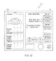
- FIGS. 16-18 illustrate various user interface screens displayed on a user interface 170 such as previously described.
- a touch screen including a liquid crystal display (LCD) and touch sensors are used, however, it will be understood by those skilled in the art that other suitable displays and/or input-output devices may also be used.
- status information is generally displayed on the left-hand side of the screen while activatable buttons are generally located on the right-hand side of the screen.
- Each of the tabs listed down the right-hand side of the screen i.e., "home”, “rotation”, “percussion”, “vibration”, “chest device”, “max inflate”, “turn assist”, and “opti-rest” relates to another user interface screen comprising information and user-activatable controls relating to the identified functional capabilities. In this way, all of the available functions are displayed at all times for easy access by the user. However, in the illustrated embodiment the screen that is currently in use or active is emphasized or offset from the inactive screens by highlighting or contrasting color.
- the user interface screen includes a portion 171 which is entitled "HOME".
- the "HOME" section enables a user to select certain tabs which initiate therapies. Those tabs can include rotation, percussion, vibration, and chest device corresponding to the chest wall oscillation device. Additional tabs are provided for adjusting mattress functions such as maximum inflate, turn assist, and Opti-rest. Opti-rest is a wave-like comfort modality with cushion pressures alternating to enhance patient comfort.
- a status section 172 indicates the status of rotation, percussion and/or vibration depending on which tabs have been selected on the right hand portion of the user interface 170.
- a rotation screen 170 indicates and provides the amount or percentage of rotation for a right, a center, and a left position at a status area 172.
- Fig. 17 illustrates an "empty" status area 172 in which no pulmonary therapy options have been initated.
- Fig. 18 illustrates a status area 172 in which rotation percentages have been set and a rotation therapy is in progress. In such event, status area 172 indicates the amount of time remaining until the therapy is complete.
- Slider bars, or arrows 173 and 174 can be used to select the desired settings. For instance, as illustrated in the right tab in which the right side of the body is lower than the left side, the rotation is set at 50% with the up down arrow 173. The pause time can be set to 15 minutes with the up down arrow 174.
- An enter button 175 is provided to finalize or to accept the settings made for pause and rotation.
- a center screen and a left screen are also provided which can be selected by touching the desired center or left tab.
- the rotation percentage and pause time can be set for both center and left.
- the rotation screen located below the status screen 172, indicates the values of rotation, pause, as well as time remaining. If either percussion and/or vibration is selected, the settings are made similarly as described with respect to the rotation screen and entered as necessary with the enter button. Once entered, the status screen 172 which includes a section for percussion and vibration shall illustrate the selected settings.
- a pause button 176 can be used to pause the selected treatments and then return to those treatments by touching the pause button a second time. Also, if it is desired to completely stop the selected treatment, the stop button 177 can be selected to stop the selected treatment as well as to clear the previously established settings.
- the max inflate tab can be selected to inflate the cushions of the support system 10 to a maximum inflation, for instance, to enable a patient to enter and exit the bed more easily or to provide for cardio-pulmonary resuscitation.
- a turn assist tab is included and can be selected to elevate a left side or a right side of a patient to move a patient on one side or the other such that clothing and/or bed linens can be changed or removed.
- An Opti-Rest tab can be pressed to provide the wavelike comfort modality.
- FIG. 19 illustrates a head-end view of one embodiment of an elevation device 180, which may be used in place of turning/rotation bladders 90, 92.
- the elevation device 180 has two hinge points 191 and 193 and thereby provides a function of alternatingly elevating each lateral side of the head end of the support surface.
- the elevation device 180 includes a bellows type of construction as illustrated in a side view of FIG. 20 and a schematic view of FIG. 21 .
- the elevation device 180 of FIGS. 19-21 illustrated in FIG. 19 as an end view from the head end of the mattress and in FIG. 20 as a side view from one of the sides of the mattress, includes first, second, third, and fourth compartments 182, 184, 186, and 188.
- Each compartment 182, 184, 186, and 188 has a first width 185, and a second width 187.
- an outer layer of the bellows 180 includes a first length L1 and an inner layer includes a length L2.
- Each compartment 182, 184, 186, and 188 has length L2.
- the bellows 180 includes at least one fill port 190 which is used to fill the bellows or a portion thereof with a fluid such as air.
- a reinforcer 192 is used around the outer compartments of the bellows 180 to help prevent distortion due to pressure variations.
- device 180 is configured to elevate one lateral side of mattress 10, relative to the other side, and another device 180 may be positioned laterally adjacent the first device 180 to elevate the other lateral side of the mattress 10.
- one instance of device 180 is positioned to provide turning assistance or rotational therapy to a patient's left side while another instance of device 180 is positioned opposite the first instance of device 180, across the width of the mattress 10, to provide turning assistance or rotational therapy to a patient's right side.
- the first width 185 of compartments 182, 184, 186, 188 is larger than the second width 187 so that when fluid is provided through port 190 the bellows shape is created such that the height of the device 180 on the side of the compartments 182, 184, 186, 188 containing the first width 185 is higher than the height of the device on the side containing the second width 187, in order to provide the specified turning or rotation angle "A".
- reinforcer 192 also comprises an internal air flow barrier along the dashed line between points 189 and 192 of Fig. 21 , which extends into the interior region of compartments 182, 184, 186, and 188 to control air flow between first and second portions 195, 197 of the compartments 182, 184, 186, and 188.
- air can be held in either portion 195 or portion 197 to provide turning assistance, or air can be alternatingly exchanged between portion 195 and 197 to provide rotational therapy.
- portion 195 of compartments 182, 184, 186, and 188 when portion 195 of compartments 182, 184, 186, and 188 is inflated, device 180 is hinged at point 193.
- portion 197 of compartments 182, 184, 186, and 188 is inflated, device 180 is hinged at point 191.
- first and second widths 185, 187 are substantially the same.
- device 180 comprises a pair of longitudinally spaced bellows 181, 183 that may be operable either in concert or independently to provide turning assistance or rotational therapy.
- Each device 181, 183 includes a substantially rigid support 194, 195, which rests upon the top portion of the bellows 180 and is held thereto by straps 196, 197.
- the substantially rigid support 194 provides for a supporting surface during elevation and rotation of the head or torso portion of the patient support 10.
- the device 180 is not limited to elevation of the head or torso, but may also be used to elevate the lower extremities if placed at the foot end of the support surface.
- sections 181, 183 of device 180 may be positioned underneath leg, calf or foot portions of a patient, and portions 195, 197 may be alternatively inflated and deflated, independently or at the same time, to exercise either or both of the knee joints of a patient positioned on mattress 10.
- the elevation device 180 is constructed to provide an elevation of about thirty degrees from horizontal. Other elevations are also possible, for example by inflating less than all of the compartments 182, 184, 186, and 188. To achieve a greater degree of rotation, i.e., in the range of about 45°, a portion of the surface bladders 110 may be deflated under one side 195 while the opposite bellows 197 are inflated, or vice versa. In such event, one or more perimeter bladders/supports 40, 42, 44 provide additional support to the non-elevated side of the patient.
- a string potentiometer, one or more ball switches, or other suitable device may be operably connected to the mattress and control unit to measure and monitor the degree of rotation provided by the portions 181, 183 of device 180.
- FIG. 22 illustrates another embodiment in which the support surface 10 is placed upon a frame 200 which includes and integrated device or a number of integrated components and features which interact with and provide support for the features of the support surface 10.
- a frame 200 which includes and integrated device or a number of integrated components and features which interact with and provide support for the features of the support surface 10.
- all or a portion of the surface controls and user interfaces previously described with respect to the controllers 120, 131, 160 and also described later herein of FIG. 16 , 17 , and 18 can be integrated into the one or more of the frame siderails 209, 211.
- the frame 200 includes an integrated control system 199 including first and second connection ports 202 and 204 into which a high frequency chest wall oscillation device 215 can be connected via hoses 217, 219.
- Vest device 132 may similarly be connected to ports 202, 204.
- the support surface 10 includes an integrated percussion and vibration, rotational therapy, and low air loss wound care/prevention surface
- the surface/frame combination can provide a plurality of healthcare features in an integrated surface/frame combination.
- FIG. 23 illustrates a block diagram of a bed frame or pressure relief surface control and communication system, such as controllers 120, 131, 160, 199, including controlling and communication devices to communicate with an integrated chest wall oscillation device such as device 132 or device 215.
- the communication system includes a liquid control display (LCD) device or other user interface device 210 which receives from a user a selection of mode, mode parameters and alarm resets. This information is displayed to the user.
- the parameters can include, for example, comfort adjust, percussion, vibration, and settings for the chest wall oscillation device.
- the user interface screen is coupled to an algorithm control unit 212 which processes pressure relief algorithms for the pressure relief surface.
- pressure setpoints are determined by the algorithm control unit 212 and also algorithm control unit 212 also processes patient position monitoring, motion monitoring, and controls a compressor.
- the unit 212 also communicates with the chest wall oscillation device, power printed circuit board (PCB) and provides the control settings for the chest wall oscillation device.
- PCB power printed circuit board
- the algorithm control unit 212 communicates and is coupled to the chest wall oscillation device power board 214 by a connection 224, described further below.
- the power board 214 receives amplitude and frequency signals and directly stimulates the air generator for the chest wall oscillation device.
- the power board 214 also provides feedback to the algorithm control unit 212.
- An air control board 216 which can be located within the pressure relief surface 10 or which can be located in one or more of the previously described controllers, is also coupled to the algorithm control unit 212.
- the air control board 216 receives pressure setpoints which have been set in the algorithm control unit 212 as well as controls the valves in response to instructions either provided by the algorithm control unit 212 or which have been set by a user at the user interface or LCD 210.
- the air control board 216 also generates requests to the algorithm control unit 212 to turn the pump ON and OFF which controls the pressure in the individual air cushions or bladders.
- the support surface 10, as previously described, includes pressure sensing or force sensing transducers 218. These pressure sensing or force sensing transducers 218 are coupled to a multiplexor hub 220 which is, in turn, coupled to the algorithm control unit 212.
- the multiplexor hub 220 receives data from the transducers or sensors and retransmits the data on a bus which is located in the communication system described in FIG. 23 .
- the bus is a network bus and the network can be of one or more types, including an ECHELON network and/or controller area network (CAN).
- a gateway device 222 receives data from the bed frame first network and provides information on a second network.
- the second network transmits signal information such as head angle, side rail status, side rail button, switch presses, and patient weight.
- the first network in the described embodiment can include an ECHELON network and the second network can include a CAN.
- Interfacing an airway clearance system as a component in the mattress system may reduce the number of components required to be provided in the airway clearance system controller or eliminate the need for a separate controller. For instance, a local display may not be required at the airway clearance controller since the mattress controller display can be used to show airway clearance information and controls. Also, power and motor control may be shared by the two systems. This combined architecture requires isolation and grounding issues to be addressed.
- connection 224 may include an AC isolation transformer and be configured to use the local ground as the system reference.
- a 5 Amp AC isolation transformer may be used to isolate the airway clearance system board 214 from the AC supply, and allow the connection of the airway clearance system board 214 to the mattress system ground. If an isolation transformer is used, and an additional power relay is used to control the power to the airway clearance system board 214, Table 1 illustrates signals that may be used to communicate from the algorithm board 212 to the airway clearance system board 214.
- the POWER_RELAY signal may be used to power the airway clearance system, when requested, and the VEST_PRESENT may be used to verify that the airway clearance system is present and powered.
- the BLOWER_REQ signals control the blower motor voltage, and the BLOWER_HALL returns the motor speed.
- the DIAPHRAGM_REQ signals control the blower motor voltage, and the DIAPHRAGM_HALL returns the motor speed.
- Software algorithms correlate the speed and pressure.
- An additional input to the algorithm processor 212 may also be needed, to detect when the airway clearance system air supply is connected to the mattress air system, rather than the actual airway clearance.
- Connection 224 may alternatively include opto isolators and mechanical isolation. Optically isolated signals may be used to provide the needed airway clearance system isolation from the AC system. This configuration allows the airway clearance system board 214 to remain directly connected to the AC supply, and provides an interface with opto isolators in each direction to provide an isolated communication path between the algorithm board 212 and the airway clearance system board 214. This approach may require a level of mechanical isolation to ensure isolation.
- a relay controlled by the algorithm board 212 may be provided between the AC source and the airway clearance system board 214, for additional safety and to remove power to the airway clearance system when not in use.
- a signal indicates the connection and/or powering of the airway clearance system board 214.
- Table 2 illustrates signals that may be used to communicate from the algorithm board 212 to the airway clearance system 214.
- Table 2 illustrates signals that may be used to communicate from the algorithm board 212 to the airway clearance system 214.
- the POWER_RELAY signal is used to power the airway clearance system, when requested, and the VEST_PRESENT is used to verify that the airway clearance system is present and powered.
- the BLOWER_REQ signals controls the blower motor voltage, and the BLOWER_HALL returns the motor speed.
- the DIAPHRAGM_REQ signals controls the blower motor voltage, and the DIAPHRAGM_HALL returns the motor speed.
- Software algorithms correlate the speed and pressure. Each side of the interface provides local +5V power and ground.
- algorithm processor 212 may also be needed, to detect when the airway clearance air supply is connected to the mattress air system, rather than the actual airway clearance unit.
- the opto isolators and relay may be located on the same circuit board, and may be associated with the airway clearance board 214 to minimize the exposure of the circuitry at a high voltage.
- the opto isolated approach may have a lower electrical cost, but may have an increased mechanical cost to ensure sufficient airway clearance system isolation.
- the isolation transformer approach may provide a simpler mechanical design and better isolation, but may have an additional cost associated with the isolation transformer. The cost and risk associated with each approach will need to be evaluated to determine the best system approach for a particular implementation of the present invention.
- the airway clearance system board interface is designed to communicate with the user interface board 210 in close proximity. If the cable distance between the algorithm board 212 and the airway clearance system board 214 is a significant distance, signal conditioning may be required, using digital signals, and an interface board may need to be located physically closer to the airway clearance system board 214. Low voltage drivers, or RS232 drivers may be used to boost the signal level. The PWM to DC filtering should be done close to the airway clearance system board 214 to minimize noise on this signal. If the opto isolated approach is used, then the signals between the daughter board and airway clearance system board may need additional optical elements.
- FIG. 24 illustrates one embodiment of a user interface screen which can be used on any of the previously described controllers and interfaces as well as with the bed frame described herein with reference to FIG. 22 , where the interface can be embodied or incorporated into a siderail, head board, and/or footboard.
- the user interface screen 300 can include a variety of selectors which can be touch screen selectors, pressure sensitive buttons, and/or mechanical switches. The features which can be accessed from the user interface screen of FIG.
- selectors include a standard operating mode 302, an Opti-Rest mode 304, a rotation mode 306, an airway clearance system mode 308, a percussion mode 310, a vibration mode 312, a maximum inflate mode 314, a turn assist mode 316, and a cardio pulmonary resuscitation (CRR) assist mode 318.
- start and stop buttons 320, 322 as well as back 332 and edit buttons 324 are available.
- the user interface screen can be used to access other therapy and controls 326, setting alarms 328, and settings for a variety of features including pressure settings 330.
- FIG. 25 illustrates one example of a user interface screen 400 where percussion and vibration parameters can be set for the mattress support 10. While FIG. 24 illustrates a single selector 310 for percussion and a single selector 312 for vibration, the user interface screen of FIG. 24 may alternatively or in addition include a single button for both percussion and vibration (P&V), which upon selection accesses the user interface screen of FIG. 25 .
- P&V percussion and vibration
- the user interface screen 400 of FIG. 25 enables an individual to select percussion therapy only 402, vibration therapy only 404, or both percussion and vibration therapy 406 with a P & V selector.
- the frequency 408, 416 intensity 410, 418 and duration 412, 420 can be set for percussion and/or vibration by selecting or activating a change selector 414, 422, respectively.
- the change selectors 414, 422 access a second user interface screen (not shown) where frequency, intensity, and duration can be selected or changed for the percussion and/or vibration therapy. Once the settings for frequency and/or vibration have been changed, the selected values are displayed on the user interface screen of FIG. 25 .
- percussion frequency 408 and vibration frequency 416 are selected as a function of beats per second (bps)
- percussion intensity 410 and vibration intensity 418 are selected as being a low, medium, or high intensity
- percussion duration 412 and vibration duration 420 are selected as a value based on the number of minutes desired for the duration to occur.
- the percussion and vibration screen 400 of FIG. 25 also enables the user to select and to change the values for continuous lateral rotation therapy (CLRT) via button 424. Once button 424 is selected, the preselected values for percussion, vibration and continuous lateral rotation therapy can be started by pressing the start selector 428.
- a help button 430 can be activated to provide user information for additional details and a close button 432 can be activated to close the displayed screen 400 and return to the screen 300 of FIG. 24 .
- FIG. 26 illustrates one example of a rotation user interface screen 500 which has been accessed through the selection of the CLRT selector 424 of FIG. 25 .
- the turn (rotation) percentages 502, 504 can be selected for a patient at a left turn and a right turn and the pause 506, 508, 510 in minutes can be selected to place the patient at a particular position for the selected period of time.
- a use rotation training button 512 can be used to acclimate the patient to continuous lateral rotation therapy. By selection of this particular selector 512, the angle of rotation therapy is gradually increased to the maximum turn which has been selected.
- a rotation monitor 514 is also included and indicates the amount of time the patient has been under the rotation therapy in the most previous 24 hours.
- the user interface screen 600 of FIG. 27 is displayed. At this screen, a user can select the pulse frequency 602 in beats per second, the intensity 604 of pressure applied by the airway clearance system to the chest of a patient, and time duration 608 of the airway clearance therapy in minutes. Screen 600 also includes a help/training graphic and/or visual feature 612 to aid the caregiver in administering the airway clearance therapy.
- FIG. 28 illustrates a therapy reminder user interface screen 700.
- the therapy reminder screen 700 of FIG. 28 is displayed.
- a user can select reminders 702, 706, 710 for the therapies of rotation, percussion and vibration, and airway clearance.
- the length of time between the last therapy session and the reminders is specified at areas 704, 708, 710 for each of the rotation, percussion and vibration, and airway clearance therapies, respectively. This length of time is adjusted using button 714 to increase the delay and by using button 716 to decrease the delay.
- Other reminders are also possible. For instance, it is possible to provide an alert if rotation has been stopped for a selected period of time, which in this case is shown to be 90 minutes.
- percussion and vibration as well as airway clearance reminders can be selected for every eight hours, for instance. Once the selected time period has elapsed, an alarm, such as a visual or aural alert is made to indicate that it is time to provide the therapy. While the figures show reminders and other parameters configured for each of the available therapies, it will be understood by those skilled in the art that any combination of the available therapies may be activated or deactivated at a given time.
- an alarm settings user interface screen 800 as illustrated in FIG. 29 is displayed.
- a user can select a bed exit alarm for a sitting up position 802, a sitting on edge of bed position 804, or an out of bed condition 806. For instance, if a patient sits up and the sitting up selector 802 has been selected, whenever a patient sits up an audio or visual alarm will be activated.
- the volume level of the audio alarm which is activated can be selected by an alarm volume selector 812 which includes a negative or down volume selector 810 and a positive or up volume selector 812.
- An edge lying alarm 808 is also included which indicates to a user that a patient is lying on the bed and is close to an edge which can be a condition that is not desirable.
- FIG. 30 illustrates a therapy log user interface screen 900 which can be selected by the therapy and controls button 326 of FIG. 24 .
- the therapy log user interface screen 900 can be used to review data which has been stored regarding the various selected therapies over a period of time, for instance, 24 hours as illustrated in FIG. 30 .
- the details of rotation 902, head elevation 904, percussion and vibration 906, alarms activated 908, and airway clearance 910 can be displayed.
- a visual bar graph of rotation is shown in area 902 as well as the actual hours and minutes of time a patient has experienced rotation. Head elevation is also shown in area 904 as a series of icons which show a horizontal state, a partially elevated state and a more highly elevated state or sitting up state for the patient.
- Percussion and vibration is illustrated in area 906 by a bar located along a time line of zero to 24 hours to indicate when the percussion and vibration has been applied to a patient. In this instance, three treatments have been applied over a period of 24 hours.
- the alarms portion 908 of the user interface screen 900 one alarm occurred over the 24 hour period as shown by the 24 hour time line and as indicated by the statement of one alarm.
- the airway clearance portion 910 of the therapy log 900 there have been no treatments over the last 24 hours. However, the portion of the airway clearance area 910 indicates that the last treatment was five days ago. Consequently, if there has been no airway clearance procedures performed over the last 24 hours, the system can display when the last treatment occurred. It is also possible to display similar information for the other four displayed functions. For instance, if there have been no percussion and vibration treatments over the last 24 hours, it is possible to display the number of days which has elapsed since the last treatment.
Landscapes
- Health & Medical Sciences (AREA)
- Veterinary Medicine (AREA)
- Life Sciences & Earth Sciences (AREA)
- Animal Behavior & Ethology (AREA)
- General Health & Medical Sciences (AREA)
- Public Health (AREA)
- Nursing (AREA)
- Pain & Pain Management (AREA)
- Physical Education & Sports Medicine (AREA)
- Rehabilitation Therapy (AREA)
- Epidemiology (AREA)
- Otolaryngology (AREA)
- Invalid Beds And Related Equipment (AREA)
- Percussion Or Vibration Massage (AREA)
Abstract
Description
- The present disclosure relates to support surfaces, such as mattresses. More particularly, the present invention relates to support surfaces used to support a patient on a bed frame, such as in a hospital or other patient care environment. Even more particularly, the present invention relates to support surfaces for patients that require pulmonary therapy.
- Known hospital beds and mattresses are disclosed, for example, in
U.S. Patent No. 4,949,413 to Goodwin ,U.S. Patent No. 5,647,079 to Hakamiun et al. ,U.S. Patent No. 5,731,062 to Kim et al. ,U.S. Patent No. 6,269,504 to Romano et al. ,U. S. Patent No. 6,701,556 to Romano et al. ,U.S. Patent No. 6,708,352 to Salvatini et al. , andU.S. Patent No. 6,820,630 to Hand et al. , all of which are assigned to the assignee of the present invention and all of which are incorporated herein reference herein in their entirety. - The present invention may comprise one or more of the features recited in the appended claims and/or one or more of the following features or combinations thereof.
- According to one aspect of the present invention there is provided a patient support surface including a cover defining an interior region, a layer of three dimensional material, located at the interior region, the three-dimensional material including a network of thermoplastic fibers, an air circulation device disposed adjacent the layer of three dimensional material, and at least one of a percussion and a vibration device, located at the interior region.
- According to another aspect of the present invention there is provided a patient support surface including a cover defining an interior region, a layer of three dimensional material, located at the interior region, the three-dimensional material including a network of thermoplastic fibers, an air circulation device disposed adjacent the layer of three dimensional material, and a hose, located at the interior region, including at least one connector adapted to couple to an external device.
- Pursuant to another aspect of the present invention there is provided a hospital bed including a frame, to support a patient, and a support surface; located on the frame. The support surface includes a cover defining an interior region and a layer of three dimensional material, located at the interior region. The three-dimensional material includes a network of thermoplastic fibers, an air circulation device disposed adjacent the layer of three dimensional material, and at least one of a percussion and a vibration device, located at the interior region.
- According to still another aspect of the present invention there is provided a patient support surface having a head end and a foot end. The patient support surface includes a cover defining an interior region, a layer of three dimensional material, located at the interior region, the three-dimensional material including a network of thermoplastic fibers, an air circulation device disposed adjacent the layer of three dimensional material, and a head elevation device, located at the head end of the patient support surface, the head elevation device including a support surface to elevate the head end of the patient support surface.
- The invention will now be further described by way of example with reference to the accompanying drawings in which:
-
FIG. 1 illustrates a perspective view of a pressure relief support surface including a slot for an x-ray cassette; -
FIG. 2 illustrates an exploded perspective view of a multi-layered pressure relief support surface; -
FIGS. 3, 4, and 5 illustrate a perspective view a pressure relief support surface and an x-ray cassette at is passes through a slot; -
FIG. 6 illustrates a perspective view of a multi-layered pressure relief support surface including percussion and vibration bladders; -
FIG. 7 illustrates an exploded perspective view of sensors with respect to cushion sections; -
FIG. 8 illustrates a perspective view of a multi-layered pressure relief support surface with turn assist bladders; -
FIG. 9 illustrates a sectional view of the support surface ofFIG. 1 along a line 9-9; -
FIGS 10-12 illustrate perspective view of a controller including user interface; -
FIG. 13 illustrates a perspective view of an airway clearance system integrated with a pressure relief support surface through a control unit; -
FIG. 14 illustrates a perspective view of an airway clearance system integrated directly with a pressure relief support surface; -
FIG. 15 illustrates a perspective view of a control unit with a holder for a deep vein thrombosis device; -
FIGS. 16-18 illustrate user interface screens of the present invention; -
FIG. 19 illustrates an end view of one embodiment of an elevation device; -
FIG. 20 illustrates a side view of one embodiment of an elevation device; -
FIG. 21 illustrates a schematic illustration ofFIG. 19 ; -
FIG. 22 illustrates a pressure relief support surface and a frame including integrated device; -
FIG. 23 illustrates a block diagram of a control and communication system; and -
FIGS. 24-30 illustrate additional user interface screens of the present invention. -
FIG. 1 illustrates a perspective view of a pressurerelief support surface 10, or mattress, including aslot 26 for inserting anx-ray cassette 27. The pressurerelief support surface 10 includes acover 12 which surrounds a plurality of components to be described later herein. Thecover 12 includes atop surface 14 and abottom surface 16, each of which is coupled together bylongitudinal sides first end portion 22 located at ahead end 23 of thesurface 10 and asecond end portion 24 located at afoot end 25 of thesurface 10 complete thecover 12.Slot 26 includes an aperture located along at least one of thelongitudinal sides Slot 26 provides for placement of anx-ray cassette 27 beneath thetop surface 14 of thecover 12. - Such pressure relief support surfaces are typically used in health care facilities such as hospitals, nursing homes, and extended care facilities. The use of such surfaces is not limited to such facilities, however, and can be used where there is a need, including the home.
- In the illustrated embodiment, the
slot 26 extends from oneside 18 ofsurface 10 to theother side 20. Theslot 26 includes a second aperture located along thelongitudinal side 20 and provides for passage of thex-ray cassette 27 from afirst side 18 of themattress 10 to asecond side 20 of themattress 10. The interior region of theslot 26, located betweensides mattress 10, includes a low friction material to facilitate insertion and removal of thex-ray cassette 27 without disturbing a patient positioned on themattress 10. Theslot 26 includes a length, L, which is greater than a width, W, of thex-ray cassette 27. In addition, thelongitudinal slot 26 is disposed along a central portion of thesupport surface 10. Accordingly, that thex-ray cassette 27 can be positioned at a number of locations along the support surface and beneath a patient. While thelongitudinal slot 26 is shown disposed towards a central portion of thesupport surface 10, the longitudinal slot can be disposed closer to the head end or the foot end portions of thesupport surface 10. Additional slots can be included as well. Also, the length L of the slot is not fixed but can be selected to accommodate a variety of sizes ofx-ray cassettes 27 as well as to accommodate a variety of positions of thex-ray cassette 27 beneath a patient. For instance, theslot 26 as illustrated enables the caregiver to position thex-ray cassette 27 along or underneath the torso portion of a patient. - The pressure
relief support surface 10 includes a head ofbed indicator 30. The head ofbed indicator 30 includes alight 32 or other illumination device which indicates when the head of the bed (HOB) elevation passes a certain predetermined elevation. In one instance, when the head of bed elevation passes thirty degrees, theindicator 32 will light thereby indicating that the desired elevation has been reached. Because the pressurerelief support service 10 can be used on any number of bed frames, including those which are fixed in a horizontal plane and those which are continuously or partially adjustable, the head ofbed indicator 30 can be either permanently or detachably coupled to thesupport surface 10. -
FIG. 2 illustrates an exploded perspective view of the multilayered pressurerelief support surface 10. As illustrated inFIG. 2 , thecover 12 including theslot 26 is shown at the bottom of the figure and is separated from the remaining layers or components of the pressurerelief support surface 10. A perimeter cushion system is disposed within thecover 12 and includes a first section orportion 40, a second section orportion 42, and a third section orportion 44. The perimeter cushion system provides a side and end support of thesupport surface 10 such that a patient subjected to either turn assist or rotational therapy, to be described later herein, can be cradled to help maintain the patient's location within a central portion of thesurface 10. - The
first section 40 includes a plurality of pieces as illustrated each of which can be either completely separated from an adjacent piece or coupled thereto but still including therebetween a separation line. The use of distinct individual pieces either completely separated or coupled to adjacent pieces provides for articulation of thesupport surface 10 when used on an articulateable frame. As can be seen, thefirst section 40 includes first andsecond end portions 46, first and secondhead end portions 48, first and sectionfoot end portions 50, first andsecond thigh portions 52, and first, second, third, andfourth middle portions 54. While a predetermined number of individual portions are illustrated, it is possible to incorporate more or less portions than shown depending on the application of the mattress and its use with a bed frame. - Each of the
portions second section 42. Thesecond section 42 includes first and secondhead end portions 56, first and secondfoot end portions 58, first andsecond thigh portions 60, and first, second, third, andfourth middle portions 62. - Each of the portions of the
second section 42 include angled side walls which cooperate with and which contact the angled side walls of the portions of thefirst section 40 corresponding thereto. The height of the portions of thesecond section 42 are less than the height of the individual portions of thefirst section 40. When thesecond section 42 is placed within thefirst section 40, each of theportions 42 cooperate to define a substantiallyhorizontal surface 64 upon which thethird section 44 can be placed. - The
third section 44 includes a plurality of perimeter bolsters including first and secondhead end portions 66, first and secondfoot end portions 68, first and second headend side portions 70, first and second footend side portions 72, first andsecond thigh portions 74, and first, second, third and fourthmiddle portions 76. Each of the portions of thethird section 44 are separable from adjacent portions or are coupled for flexibility when used with an articulated deck. In addition, the first and second parts of theportion 66 are spaced apart to define agap 67 and a similar space orgap 69 exists between the first andsecond portions 68. When thefirst section 40, thesecond section 42, and thethird section 44 are assembled together, thespace 67 between theportions 66 and thespace 69 between theportions 68 correspond to spaces, respectively 80 and 82 of the first section. Thespaces fan 84 and a second fan orcirculation device 86, to be described later herein. - A plurality of
pressure sensors 88 are located and disposed above turning/rotation air bladders rotation bladders pressure sensors 88 include afirst section 94, asecond section 96, athird section 98, afourth section 100, and afifth section 102. Each of the plurality of pressure sensor sections provide a single signal which indicates a pressure amount being supported byrespective sections 110 of air cushions. In particular, eachsection 110 can include a plurality of upstanding air cushions having a cylindrical shape. Other types of cushions or bladders are possible. - Each of the sections of upstanding cells or air cushions includes a plurality which is disposed directly upon a corresponding pressure sensor section. Consequently, when a patient lies upon the pressure
relief support surface 10, patient pressures upon different portions of thesurface 10 can be individually determined by the pressure or force sensor located therebelow. Consequently, pressures for head portions, upper body portions, middle portions, side portions, and leg portions, and other portions of a patient can be individualized for each patient's body. - Each of the
sections 110 of cells includes upstanding cylinders or inflatable cushions which have spaces disposed therebetween. Within the spaces of the upper body section, a thermo-regulation device 112 can be disposed. Thedevice 112 provides for thermal regulation of a patient and can cool and warm a patient. Thedevice 112 can include any number of thermal regulation mechanisms, however, thepresent device 112 includes a plurality of fluid filled or water filled chambers which are disposed between the spaces of thehead end section 110 for the upper body portion. As fluid or water is moved through thethermal regulation device 112, it is circulated beneath a patient to provide cooling or heating to the patient's upper body. Fluid flow or water flow can move in one direction throughout the device, as would be understood by one skilled in the art, and passes through a controlling device (not shown) which includes a pump and a mechanism for thermal regulation of the fluid. - A
topper 114 is located above thesections 110. The topper includes a three dimensional material or a three dimensional fiber network made of a breathable fabric or other known three dimensional materials. One such material is known as SPACENET® material. For a further discussion of three dimensional materials, seeU.S. Patent Nos. 7,191,482 ;6,701,556 ; and6,269,504 . - The three
dimensional material 114 enables theair circulators topper 114. Theair circulators circulators 86 is used to push air through the topper and the other air circulator is used to pull air through the topper. Consequently, air flow can be directed in a single direction. - A percussion and
vibration system 116 is included and disposed at an upper body portion of thesupport surface 10. The percussion and vibration system provides for the percussion and vibration of a chest portion of a patient as is understood by one of ordinary skill in the art. Percussion and vibration systems are known and can include a plurality of air bladders, three of which are illustrated. -
FIGS. 3, 4, and 5 illustrate a partial perspective view of thex-ray cassette 27 as it passes through theslot 26. WhileFIGS. 3 and 4 do not illustrate one of the portions of thetopper 114, thex-ray cassette 26 when in use can be located above the upper body portion of thetopper 114. -
FIG. 6 illustrates a perspective view of the multi-layered pressurerelief support surface 10 without thecover 12. In this illustration, the percussion andvibration bladder 116 is located in the upper body portion of themattress 10 to provide percussion and/or vibration to the chest area of a patient. -
FIG. 7 illustrates the arrangement of thepressure sensors 88 with respect to thecushion sections 110. Theindividual sections 110 have been moved closer together to illustrate that the upstanding cushions when assembled provide a substantially continuous support surface without gaps between sections as is illustrated inFIG. 2 . The individual sections of thepressure sensors 88 have also been moved closer together and the entire combination fits within the cavity defined by thefirst section 40,second section 42, andthird section 44 of the perimeter cushion system ofFIG. 2 . In other embodiments, horizontal, laterally-oriented or log-shaped bladders may be used in place of one or more of the upstanding cushion sections. -
FIG. 8 illustrates the various portions and layers ofFIG. 2 excluding thecover 12 and thex-ray cassette 27. The turning/rotation bladders -
FIG. 9 illustrates a sectional view of thesupport surface 10 ofFIG. 1 along a line 9-9. As previously described, and as seen here in additional detail, theportions 58 are in contact with theportions 50 of thefirst section 40 and define an interface therebetween along the angled side walls of each. Thesection 72 of thethird section 44 sits upon a substantially flat and horizontally disposed top surface of theportion 50. Also, as can be seen, theupstanding cushions 110 are located above thepressure sensors 102. -
FIGS. 10-12 illustrate acontroller 120 including auser interface 122. Theuser interface 122 is coupled to thecontroller 120 through a swivelingmechanism 124 which enables the 122 to lay substantially flat against atop portion 126 of thecontroller 120. The swivelingmechanism 124 enables the pivoting screen to move about an axis substantially parallel to the long dimension of thecontroller 120. The swiveling mechanism also includes arotating portion 128 which enables theinterface 122 to rotate about an axis substantially vertical with respect to the plane of thetop portion 126. The swivelingmechanism 124 androtating portion 128 in combination provide an adjustment capability which allows the pivoting interface to be moved in a variety of positions for improving access of theinterface 122 to a user or caregiver. The user interface can include a variety of selectors which can include touch screen selectors, pressure sensitive buttons, and/or mechanical switches. Other later described screens can include the same selectors. The user interface can also include an electronic display, such as an liquid crystal diode (LCD) display which can display user interface screens to be described later herein. -
FIG. 13 illustrates a perspective view of anairway clearance system 130 integrated with a support surface through acontrol unit 131. The mattress orsupport surface 10 is illustrated with thecover 12 but not including theslot 26, which can be optional. Theairway clearance system 130 includes a high frequency chestwall oscillation device 132 which is coupled to thecontrol unit 131. One example of such a device is available from Hill-Rom, Inc. as The Vest® airway clearance system. - The
control unit 131 provides for chest wall oscillation through the use of forced air which is moved through first andsecond tubes controller 131 through first andsecond couplers tubes upper body portion 144 which surrounds the chest wall and provides high frequency chest wall oscillations for the purpose of airway lung clearance and ventilation as described inU.S. Patent 6,736,785 , which is incorporated in its entirety by reference herein. - As illustrated in
FIG. 13 , thecontroller 131 is coupled to theupper body portion 144 and enables a patient or other user who may or may not be located on thesupport surface 10 to use theairway clearance system 130. For instance, when a patient is sufficiently mobile to move within a facility and to sit in a chair within a hospital room, the patient can wear theupper body portion 144 when seated in a chair. As further illustrated inFIG. 14 , the controller 134 can also be coupled directly to thesupport surface 10 through ahose 150. Thehose 150 is coupled to aconnector 152 which is in turn coupled to aninternal hose device 154 which passes through and is incorporated in thesupport surface 10. A first and asecond connector hose 150. Using thisconnection upper body portion 144 when lying in bed to provide the chest wall oscillation. Whencontroller 131 detects connection of anairway clearance system 132,controller 131 automatically disables or bypasses the mattress pulmonary therapy functions and thecontroller user interface 123 is automatically updated to visually indicate the status of a connection or disconnection of the airway clearance system. In this way,controller 131 can be used to control inflation and deflation of bladder portions ofmattress 10 and/or to control operation of theairway clearance system 132. As such, the need to provide multiple separate control units (i.e., a mattress controller and an airway clearance system controller) may be eliminated. - Alternatively or in addition,
controller 131 is sized and shaped so that a separate airway clearance system controller is stackable on top of or underneathcontroller 131, to thereby conserve space in the patient's healthcare environment.Controller 131 may include all or a portion of the features ofcontrol unit 120 orcontrol unit 160. -
FIG. 15 illustrates a perspective view of acontrol unit 160 having aholder 162 which can be used to support a deep vein thrombosis device (DVT) 164 by insertion intoholder 162 as indicated byarrow 163. A cuff is generally provided withDVT device 164 but is not illustrated. Thecontroller 160 includes afirst attachment device 166 andsecond attachment device 168.Devices controller 160 on a footboard, headboard, and/or side rail of a patient support frame. Thecontroller 160 includes auser interface 170 which is fixed and coupled to thecontroller 160. TheDVT device 164 can be used to provide pneumatic pressure to a body limb to reduce or to prevent deep vein thrombosis. For additional details, please seeU.S. Patent Nos. 6,447,467 andU.S. 6,494,852 . -
FIGS. 16-18 illustrate various user interface screens displayed on auser interface 170 such as previously described. In the illustrated embodiments, a touch screen, including a liquid crystal display (LCD) and touch sensors are used, however, it will be understood by those skilled in the art that other suitable displays and/or input-output devices may also be used. Also, in the embodiment ofFIGS. 16-18 , status information is generally displayed on the left-hand side of the screen while activatable buttons are generally located on the right-hand side of the screen. Each of the tabs listed down the right-hand side of the screen, i.e., "home", "rotation", "percussion", "vibration", "chest device", "max inflate", "turn assist", and "opti-rest" relates to another user interface screen comprising information and user-activatable controls relating to the identified functional capabilities. In this way, all of the available functions are displayed at all times for easy access by the user. However, in the illustrated embodiment the screen that is currently in use or active is emphasized or offset from the inactive screens by highlighting or contrasting color. - For example, as illustrated in
FIG. 16 , the user interface screen includes aportion 171 which is entitled "HOME". The "HOME" section enables a user to select certain tabs which initiate therapies. Those tabs can include rotation, percussion, vibration, and chest device corresponding to the chest wall oscillation device. Additional tabs are provided for adjusting mattress functions such as maximum inflate, turn assist, and Opti-rest. Opti-rest is a wave-like comfort modality with cushion pressures alternating to enhance patient comfort. Astatus section 172 indicates the status of rotation, percussion and/or vibration depending on which tabs have been selected on the right hand portion of theuser interface 170. - As further illustrated in
FIG. 17 , should the rotation tab be selected, arotation screen 170 indicates and provides the amount or percentage of rotation for a right, a center, and a left position at astatus area 172.Fig. 17 illustrates an "empty"status area 172 in which no pulmonary therapy options have been initated.Fig. 18 illustrates astatus area 172 in which rotation percentages have been set and a rotation therapy is in progress. In such event,status area 172 indicates the amount of time remaining until the therapy is complete. - Slider bars, or
arrows arrow 173. The pause time can be set to 15 minutes with the up downarrow 174. Anenter button 175 is provided to finalize or to accept the settings made for pause and rotation. In addition to the right screen, a center screen and a left screen are also provided which can be selected by touching the desired center or left tab. As described with respect to the right screen, the rotation percentage and pause time can be set for both center and left. Once the right, center and left settings have been selected, theenter button 175 is selected to enter the data into the controller. The rotation screen, located below thestatus screen 172, indicates the values of rotation, pause, as well as time remaining. If either percussion and/or vibration is selected, the settings are made similarly as described with respect to the rotation screen and entered as necessary with the enter button. Once entered, thestatus screen 172 which includes a section for percussion and vibration shall illustrate the selected settings. Apause button 176 can be used to pause the selected treatments and then return to those treatments by touching the pause button a second time. Also, if it is desired to completely stop the selected treatment, thestop button 177 can be selected to stop the selected treatment as well as to clear the previously established settings. - The max inflate tab can be selected to inflate the cushions of the
support system 10 to a maximum inflation, for instance, to enable a patient to enter and exit the bed more easily or to provide for cardio-pulmonary resuscitation. A turn assist tab is included and can be selected to elevate a left side or a right side of a patient to move a patient on one side or the other such that clothing and/or bed linens can be changed or removed. An Opti-Rest tab can be pressed to provide the wavelike comfort modality. -
FIG. 19 illustrates a head-end view of one embodiment of anelevation device 180, which may be used in place of turning/rotation bladders elevation device 180 has twohinge points elevation device 180 includes a bellows type of construction as illustrated in a side view ofFIG. 20 and a schematic view ofFIG. 21 . Theelevation device 180 ofFIGS. 19-21 , illustrated inFIG. 19 as an end view from the head end of the mattress and inFIG. 20 as a side view from one of the sides of the mattress, includes first, second, third, andfourth compartments compartment first width 185, and asecond width 187. - As shown in
FIG. 21 , an outer layer of thebellows 180 includes a first length L1 and an inner layer includes a length L2. Eachcompartment fill port 190 which is used to fill the bellows or a portion thereof with a fluid such as air. Areinforcer 192 is used around the outer compartments of thebellows 180 to help prevent distortion due to pressure variations. - In the illustrated embodiment,
device 180 is configured to elevate one lateral side ofmattress 10, relative to the other side, and anotherdevice 180 may be positioned laterally adjacent thefirst device 180 to elevate the other lateral side of themattress 10. For instance, one instance ofdevice 180 is positioned to provide turning assistance or rotational therapy to a patient's left side while another instance ofdevice 180 is positioned opposite the first instance ofdevice 180, across the width of themattress 10, to provide turning assistance or rotational therapy to a patient's right side. In this embodiment, thefirst width 185 ofcompartments second width 187 so that when fluid is provided throughport 190 the bellows shape is created such that the height of thedevice 180 on the side of thecompartments first width 185 is higher than the height of the device on the side containing thesecond width 187, in order to provide the specified turning or rotation angle "A". - In one alternative embodiment, referred to herein as the "dual hinge" embodiment,
reinforcer 192 also comprises an internal air flow barrier along the dashed line betweenpoints Fig. 21 , which extends into the interior region ofcompartments second portions compartments portion 195 orportion 197 to provide turning assistance, or air can be alternatingly exchanged betweenportion portion 195 ofcompartments device 180 is hinged atpoint 193. Whenportion 197 ofcompartments device 180 is hinged atpoint 191. In the dual hinged embodiment, first andsecond widths - As can be seen in
FIGS. 19 and 20 ,device 180 comprises a pair of longitudinally spaced bellows 181, 183 that may be operable either in concert or independently to provide turning assistance or rotational therapy. Eachdevice 181, 183 includes a substantiallyrigid support bellows 180 and is held thereto bystraps rigid support 194 provides for a supporting surface during elevation and rotation of the head or torso portion of thepatient support 10. - The
device 180 is not limited to elevation of the head or torso, but may also be used to elevate the lower extremities if placed at the foot end of the support surface. For example, either or both ofsections 181, 183 ofdevice 180 may be positioned underneath leg, calf or foot portions of a patient, andportions mattress 10. - In one embodiment, the
elevation device 180 is constructed to provide an elevation of about thirty degrees from horizontal. Other elevations are also possible, for example by inflating less than all of thecompartments surface bladders 110 may be deflated under oneside 195 while the opposite bellows 197 are inflated, or vice versa. In such event, one or more perimeter bladders/supports 40, 42, 44 provide additional support to the non-elevated side of the patient. A string potentiometer, one or more ball switches, or other suitable device may be operably connected to the mattress and control unit to measure and monitor the degree of rotation provided by theportions 181, 183 ofdevice 180. -
FIG. 22 illustrates another embodiment in which thesupport surface 10 is placed upon aframe 200 which includes and integrated device or a number of integrated components and features which interact with and provide support for the features of thesupport surface 10. For instance, all or a portion of the surface controls and user interfaces previously described with respect to thecontrollers FIG. 16 ,17 , and18 can be integrated into the one or more of theframe siderails frame 200 includes anintegrated control system 199 including first andsecond connection ports wall oscillation device 215 can be connected viahoses Vest device 132 may similarly be connected toports Fig. 22 , aspects of thecontroller 131 ofFIG. 13 are incorporated into theframe control system 199. Because thesupport surface 10 includes an integrated percussion and vibration, rotational therapy, and low air loss wound care/prevention surface, the surface/frame combination can provide a plurality of healthcare features in an integrated surface/frame combination. -
FIG. 23 illustrates a block diagram of a bed frame or pressure relief surface control and communication system, such ascontrollers device 132 ordevice 215. The communication system includes a liquid control display (LCD) device or otheruser interface device 210 which receives from a user a selection of mode, mode parameters and alarm resets. This information is displayed to the user. The parameters can include, for example, comfort adjust, percussion, vibration, and settings for the chest wall oscillation device. The user interface screen is coupled to analgorithm control unit 212 which processes pressure relief algorithms for the pressure relief surface. In addition, pressure setpoints are determined by thealgorithm control unit 212 and alsoalgorithm control unit 212 also processes patient position monitoring, motion monitoring, and controls a compressor. Theunit 212 also communicates with the chest wall oscillation device, power printed circuit board (PCB) and provides the control settings for the chest wall oscillation device. - The
algorithm control unit 212 communicates and is coupled to the chest wall oscillationdevice power board 214 by aconnection 224, described further below. Thepower board 214 receives amplitude and frequency signals and directly stimulates the air generator for the chest wall oscillation device. Thepower board 214 also provides feedback to thealgorithm control unit 212. - An
air control board 216, which can be located within thepressure relief surface 10 or which can be located in one or more of the previously described controllers, is also coupled to thealgorithm control unit 212. Theair control board 216 receives pressure setpoints which have been set in thealgorithm control unit 212 as well as controls the valves in response to instructions either provided by thealgorithm control unit 212 or which have been set by a user at the user interface orLCD 210. Theair control board 216 also generates requests to thealgorithm control unit 212 to turn the pump ON and OFF which controls the pressure in the individual air cushions or bladders. - The
support surface 10, as previously described, includes pressure sensing orforce sensing transducers 218. These pressure sensing orforce sensing transducers 218 are coupled to amultiplexor hub 220 which is, in turn, coupled to thealgorithm control unit 212. Themultiplexor hub 220 receives data from the transducers or sensors and retransmits the data on a bus which is located in the communication system described inFIG. 23 . The bus is a network bus and the network can be of one or more types, including an ECHELON network and/or controller area network (CAN). To provide communication between the bed frame and various other described features, agateway device 222 receives data from the bed frame first network and provides information on a second network. The second network transmits signal information such as head angle, side rail status, side rail button, switch presses, and patient weight. The first network in the described embodiment can include an ECHELON network and the second network can include a CAN. - Interfacing an airway clearance system as a component in the mattress system may reduce the number of components required to be provided in the airway clearance system controller or eliminate the need for a separate controller. For instance, a local display may not be required at the airway clearance controller since the mattress controller display can be used to show airway clearance information and controls. Also, power and motor control may be shared by the two systems. This combined architecture requires isolation and grounding issues to be addressed.
- Accordingly,
connection 224 may include an AC isolation transformer and be configured to use the local ground as the system reference. For example, a 5 Amp AC isolation transformer may be used to isolate the airwayclearance system board 214 from the AC supply, and allow the connection of the airwayclearance system board 214 to the mattress system ground. If an isolation transformer is used, and an additional power relay is used to control the power to the airwayclearance system board 214, Table 1 illustrates signals that may be used to communicate from thealgorithm board 212 to the airwayclearance system board 214.TABLE 1 SIGNAL TYPE DESCRIPTION BLOWER_REQ OUT PWM to DC signal - control blower speed BLOWER_HALL IN Hall sensor - blower motor speed DIAPHRAGM_REQ OUT PWM to DC signal - control diaphragm speed DIAPHRAGM_HALL IN Hall sensor - diaphragm motor speed POWER_RELAY OUT Relay control for VEST power relay VEST_PRESENT IN VEST system is present/powered signal GND GROUND Signal ground - mattress side - The POWER_RELAY signal may be used to power the airway clearance system, when requested, and the VEST_PRESENT may be used to verify that the airway clearance system is present and powered. The BLOWER_REQ signals control the blower motor voltage, and the BLOWER_HALL returns the motor speed. The DIAPHRAGM_REQ signals control the blower motor voltage, and the DIAPHRAGM_HALL returns the motor speed. Software algorithms correlate the speed and pressure.
- An additional input to the
algorithm processor 212 may also be needed, to detect when the airway clearance system air supply is connected to the mattress air system, rather than the actual airway clearance. -
Connection 224 may alternatively include opto isolators and mechanical isolation. Optically isolated signals may be used to provide the needed airway clearance system isolation from the AC system. This configuration allows the airwayclearance system board 214 to remain directly connected to the AC supply, and provides an interface with opto isolators in each direction to provide an isolated communication path between thealgorithm board 212 and the airwayclearance system board 214. This approach may require a level of mechanical isolation to ensure isolation. A relay controlled by thealgorithm board 212 may be provided between the AC source and the airwayclearance system board 214, for additional safety and to remove power to the airway clearance system when not in use. A signal indicates the connection and/or powering of the airwayclearance system board 214. - If the opto isolator approach is used, and an additional power relay is used to control the power to the airway clearance system board, Table 2 illustrates signals that may be used to communicate from the
algorithm board 212 to theairway clearance system 214.TABLE 2 SIGNAL TYPE DESCRIPTION +5V POWER Interface power - mattress side BLOWER_REQ OUT PWM to DC signal - control blower speed BLOWER_HALL IN Hall sensor - blower motor speed DIAPHRAGM_REG OUT PWM to DC signal - control diaphragm speed DIAPHRAGM_HALL IN Hall sensor - diaphragm motor speed POWER_RELAY OUT Relay control for VEST power relay VEST_PRESENT IN VEST system is present/powered signal GND GROUND Signal ground - mattress side - The POWER_RELAY signal is used to power the airway clearance system, when requested, and the VEST_PRESENT is used to verify that the airway clearance system is present and powered. The BLOWER_REQ signals controls the blower motor voltage, and the BLOWER_HALL returns the motor speed. the DIAPHRAGM_REQ signals controls the blower motor voltage, and the DIAPHRAGM_HALL returns the motor speed. Software algorithms correlate the speed and pressure. Each side of the interface provides local +5V power and ground.
- As additional input to the
algorithm processor 212 may also be needed, to detect when the airway clearance air supply is connected to the mattress air system, rather than the actual airway clearance unit. - The opto isolators and relay may be located on the same circuit board, and may be associated with the
airway clearance board 214 to minimize the exposure of the circuitry at a high voltage. - Two possible configurations for the mattress - airway clearance system interface are described above. Each approach has associated pro and cons. The opto isolated approach may have a lower electrical cost, but may have an increased mechanical cost to ensure sufficient airway clearance system isolation. The isolation transformer approach may provide a simpler mechanical design and better isolation, but may have an additional cost associated with the isolation transformer. The cost and risk associated with each approach will need to be evaluated to determine the best system approach for a particular implementation of the present invention.
- The airway clearance system board interface is designed to communicate with the
user interface board 210 in close proximity. If the cable distance between thealgorithm board 212 and the airwayclearance system board 214 is a significant distance, signal conditioning may be required, using digital signals, and an interface board may need to be located physically closer to the airwayclearance system board 214. Low voltage drivers, or RS232 drivers may be used to boost the signal level. The PWM to DC filtering should be done close to the airwayclearance system board 214 to minimize noise on this signal. If the opto isolated approach is used, then the signals between the daughter board and airway clearance system board may need additional optical elements. -
FIG. 24 illustrates one embodiment of a user interface screen which can be used on any of the previously described controllers and interfaces as well as with the bed frame described herein with reference toFIG. 22 , where the interface can be embodied or incorporated into a siderail, head board, and/or footboard. As illustrated inFIG. 24 , theuser interface screen 300 can include a variety of selectors which can be touch screen selectors, pressure sensitive buttons, and/or mechanical switches. The features which can be accessed from the user interface screen ofFIG. 24 via selectors include astandard operating mode 302, an Opti-Rest mode 304, a rotation mode 306, an airwayclearance system mode 308, apercussion mode 310, avibration mode 312, a maximum inflatemode 314, a turn assistmode 316, and a cardio pulmonary resuscitation (CRR) assistmode 318. In addition, start and stopbuttons buttons 324 are available. Likewise, the user interface screen can be used to access other therapy and controls 326, settingalarms 328, and settings for a variety of features includingpressure settings 330. -
FIG. 25 illustrates one example of auser interface screen 400 where percussion and vibration parameters can be set for themattress support 10. WhileFIG. 24 illustrates asingle selector 310 for percussion and asingle selector 312 for vibration, the user interface screen ofFIG. 24 may alternatively or in addition include a single button for both percussion and vibration (P&V), which upon selection accesses the user interface screen ofFIG. 25 . - The
user interface screen 400 ofFIG. 25 enables an individual to select percussion therapy only 402, vibration therapy only 404, or both percussion andvibration therapy 406 with a P & V selector. In addition, thefrequency intensity duration change selector change selectors FIG. 25 . For instance, in the illustrated embodiment,percussion frequency 408 andvibration frequency 416 are selected as a function of beats per second (bps),percussion intensity 410 andvibration intensity 418 are selected as being a low, medium, or high intensity, andpercussion duration 412 andvibration duration 420 are selected as a value based on the number of minutes desired for the duration to occur. The percussion andvibration screen 400 ofFIG. 25 also enables the user to select and to change the values for continuous lateral rotation therapy (CLRT) viabutton 424. Oncebutton 424 is selected, the preselected values for percussion, vibration and continuous lateral rotation therapy can be started by pressing thestart selector 428. Ahelp button 430 can be activated to provide user information for additional details and aclose button 432 can be activated to close the displayedscreen 400 and return to thescreen 300 ofFIG. 24 . -
FIG. 26 illustrates one example of a rotationuser interface screen 500 which has been accessed through the selection of theCLRT selector 424 ofFIG. 25 . The turn (rotation)percentages pause rotation training button 512 can be used to acclimate the patient to continuous lateral rotation therapy. By selection of thisparticular selector 512, the angle of rotation therapy is gradually increased to the maximum turn which has been selected. Arotation monitor 514 is also included and indicates the amount of time the patient has been under the rotation therapy in the most previous 24 hours. - If the
airway clearance selector 308 ofFIG. 24 is selected, theuser interface screen 600 ofFIG. 27 is displayed. At this screen, a user can select thepulse frequency 602 in beats per second, theintensity 604 of pressure applied by the airway clearance system to the chest of a patient, andtime duration 608 of the airway clearance therapy in minutes.Screen 600 also includes a help/training graphic and/orvisual feature 612 to aid the caregiver in administering the airway clearance therapy. -
FIG. 28 illustrates a therapy reminderuser interface screen 700. By selecting the therapy and controlsselector 326 ofFIG. 24 , thetherapy reminder screen 700 ofFIG. 28 is displayed. At this screen, a user can selectreminders areas button 714 to increase the delay and by usingbutton 716 to decrease the delay. Other reminders are also possible. For instance, it is possible to provide an alert if rotation has been stopped for a selected period of time, which in this case is shown to be 90 minutes. Likewise, percussion and vibration as well as airway clearance reminders can be selected for every eight hours, for instance. Once the selected time period has elapsed, an alarm, such as a visual or aural alert is made to indicate that it is time to provide the therapy. While the figures show reminders and other parameters configured for each of the available therapies, it will be understood by those skilled in the art that any combination of the available therapies may be activated or deactivated at a given time. - By selecting the
alarm selector 328 ofFIG. 24 , an alarm settingsuser interface screen 800 as illustrated inFIG. 29 is displayed. Upon selection of thisparticular interface screen 800 , a user can select a bed exit alarm for a sitting upposition 802, a sitting on edge ofbed position 804, or an out ofbed condition 806. For instance, if a patient sits up and the sitting upselector 802 has been selected, whenever a patient sits up an audio or visual alarm will be activated. The volume level of the audio alarm which is activated can be selected by analarm volume selector 812 which includes a negative or downvolume selector 810 and a positive or upvolume selector 812. If the bed exit alarm of sitting onedge 804 has been selected, even though a patient sits up in bed, an alarm will not sound. However, when a patient moves to sitting on the edge of the bed, an alarm will sound or otherwise be activated. Should the user select the out ofbed condition alarm 806, a patient in a sitting up position or a sitting on edge position will not trigger the alarm. Only when a patient exits the bed will an alarm be activated. Anedge lying alarm 808 is also included which indicates to a user that a patient is lying on the bed and is close to an edge which can be a condition that is not desirable. -
FIG. 30 illustrates a therapy loguser interface screen 900 which can be selected by the therapy and controlsbutton 326 ofFIG. 24 . The therapy loguser interface screen 900 can be used to review data which has been stored regarding the various selected therapies over a period of time, for instance, 24 hours as illustrated inFIG. 30 . The details ofrotation 902,head elevation 904, percussion andvibration 906, alarms activated 908, andairway clearance 910 can be displayed. A visual bar graph of rotation is shown inarea 902 as well as the actual hours and minutes of time a patient has experienced rotation. Head elevation is also shown inarea 904 as a series of icons which show a horizontal state, a partially elevated state and a more highly elevated state or sitting up state for the patient. Percussion and vibration is illustrated inarea 906 by a bar located along a time line of zero to 24 hours to indicate when the percussion and vibration has been applied to a patient. In this instance, three treatments have been applied over a period of 24 hours. In thealarms portion 908 of theuser interface screen 900, one alarm occurred over the 24 hour period as shown by the 24 hour time line and as indicated by the statement of one alarm. In theairway clearance portion 910 of thetherapy log 900, there have been no treatments over the last 24 hours. However, the portion of theairway clearance area 910 indicates that the last treatment was five days ago. Consequently, if there has been no airway clearance procedures performed over the last 24 hours, the system can display when the last treatment occurred. It is also possible to display similar information for the other four displayed functions. For instance, if there have been no percussion and vibration treatments over the last 24 hours, it is possible to display the number of days which has elapsed since the last treatment. - Although the invention has been described in detail with reference to certain preferred embodiments, variations and modifications exist. For instance, while the figures illustrate a surface including a plurality of upstanding air cushions having a cylindrical shape, other air cushions may be employed. Air bladder assemblies having horizontally disposed or transversely disclosed bladders are usable. Other pressure or force sensing transducers than those disclosed herein can be employed. For additional details of bladders or sensing transducers which may be used to advantage, please see
U.S. Provisional Patent Application Serial No. 60/821,494 . - Embodiments of the invention can be described with reference to the following numbered clauses, with preferred features laid out in the dependent clauses:
- 1. A patient support surface comprising a cover defining an interior region, a layer of three dimensional material, located at the interior region, the three-dimensional material including a network of thermoplastic fibers, an air circulation device disposed adjacent the layer of three dimensional material, and at least one of a percussion device and a vibration device, located at the interior region.
- 2. A patient support surface having a head end and a foot end, comprising a cover defining an interior region, a layer of three dimensional material, located at the interior region, the three-dimensional material including a network of thermoplastic fibers, an air circulation device disposed adjacent the layer of three dimensional material, and a head elevation device, located at the head end of the patient support surface, the head elevation device including a support surface to elevate the head end of the patient support surface.
- 3. The patient support surface of
clause 2, further comprising at least one of a percussion device and a vibration device, located at the interior region. - 4. The patient support surface of either
clause 1 orclause 3 further comprising a bladder, disposed at the interior region, the bladder being inflatable and adapted to provide at least one of turning and rotation. - 5. A patient support surface comprising a cover defining an interior region, a layer of three dimensional material, located at the interior region, the three-dimensional material including a network of thermoplastic fibers, an air circulation device disposed adjacent the layer of three dimensional material, and a hose, located at the interior region, including at least one connector adapted to couple to an external device.
- 6. The patient support surface of
clause 5, further wherein the coupled is adapted to couple to an airway clearance device. - 7. The patient support surface of either clause 4 or
clause 5, further comprising a plurality of cushions, disposed at the interior regions. - 8. The patient support of clause 7, further comprising a plurality of sensors, disposed at the interior region, to sense at least one of a pressure and a force.
- 9. A hospital bed comprising a frame, to support a patient, and a support surface as claimed in either
clause 1 or any one ofclauses 4, 7 and 8 as dependant onclause 1. - 10. The hospital bed of clause 9, wherein the frame comprises an integrated device, including a coupler adapted to couple to an airway clearance device.
Claims (9)
- A patient support surface having a head end and a foot end, comprising a cover defining an interior region, a layer of three dimensional material, located at the interior region, the three-dimensional material including a network of thermoplastic fibers, an air circulation device disposed adjacent the layer of three dimensional material, and a head elevation device, located at the head end of the patient support surface, the head elevation device including a support surface to elevate the head end of the patient support surface.
- The patient support surface of claim 1, further comprising at least one of a percussion device and a vibration device, located at the interior region.
- The patient support surface of claim 2 further comprising a bladder, disposed at the interior region, the bladder being inflatable and adapted to provide at least one of turning and rotation.
- The patient support surface of any preceding claim further comprising a hose, located at the interior region, including at least one connector adapted to couple to an external device.
- The patient support surface of claim 5, further wherein the connector is adapted to couple to an airway clearance device.
- The patient support surface of any preceding claim, further comprising a plurality of cushions, disposed at the interior regions.
- The patient support surface of claim 6, further comprising a plurality of sensors, disposed at the interior region, to sense at least one of a pressure and a force.
- A hospital bed comprising a frame, to support a patient, and a support surface as claimed in any preceding claim.
- The hospital bed of claim 8, wherein the frame comprises an integrated device, including a coupler adapted to couple to an airway clearance device.
Applications Claiming Priority (3)
| Application Number | Priority Date | Filing Date | Title |
|---|---|---|---|
| US94109207P | 2007-05-31 | 2007-05-31 | |
| US12/122,808 US8108957B2 (en) | 2007-05-31 | 2008-05-19 | Pulmonary mattress |
| EP08251896.0A EP1997467B1 (en) | 2007-05-31 | 2008-05-30 | Pulmonary mattress |
Related Parent Applications (1)
| Application Number | Title | Priority Date | Filing Date |
|---|---|---|---|
| EP08251896.0A Division EP1997467B1 (en) | 2007-05-31 | 2008-05-30 | Pulmonary mattress |
Publications (1)
| Publication Number | Publication Date |
|---|---|
| EP2505175A1 true EP2505175A1 (en) | 2012-10-03 |
Family
ID=39719146
Family Applications (2)
| Application Number | Title | Priority Date | Filing Date |
|---|---|---|---|
| EP12159618A Withdrawn EP2505175A1 (en) | 2007-05-31 | 2008-05-30 | Pulmonary mattress |
| EP08251896.0A Expired - Fee Related EP1997467B1 (en) | 2007-05-31 | 2008-05-30 | Pulmonary mattress |
Family Applications After (1)
| Application Number | Title | Priority Date | Filing Date |
|---|---|---|---|
| EP08251896.0A Expired - Fee Related EP1997467B1 (en) | 2007-05-31 | 2008-05-30 | Pulmonary mattress |
Country Status (2)
| Country | Link |
|---|---|
| US (3) | US8108957B2 (en) |
| EP (2) | EP2505175A1 (en) |
Cited By (4)
| Publication number | Priority date | Publication date | Assignee | Title |
|---|---|---|---|---|
| CN103385793A (en) * | 2013-08-05 | 2013-11-13 | 马广丽 | Vibromassage turn-over pad |
| US20200163818A1 (en) * | 2018-11-27 | 2020-05-28 | Stryker Corporation | Patient support apparatus with notification system |
| US10980687B2 (en) | 2017-07-19 | 2021-04-20 | Stryker Corporation | Techniques for generating auditory and haptic output with a vibrational panel of a patient support apparatus |
| USD959450S1 (en) | 2020-05-19 | 2022-08-02 | Stryker Corporation | Display screen with an animated graphical user interface |
Families Citing this family (80)
| Publication number | Priority date | Publication date | Assignee | Title |
|---|---|---|---|---|
| US6584628B1 (en) | 1995-08-04 | 2003-07-01 | Hill-Rom Services, Inc. | Hospital bed having a rotational therapy device |
| US9462893B2 (en) | 1998-05-06 | 2016-10-11 | Hill-Rom Services, Inc. | Cover system for a patient support surface |
| DE69918824T2 (en) * | 1998-05-06 | 2004-11-25 | Hill-Rom Services, Inc., Batesville | MATTRESS / CUSHION CONSTRUCTION |
| EP2181685B1 (en) * | 2002-09-06 | 2014-05-14 | Hill-Rom Services, Inc. | Hospital bed with controlled inflatable portion of patient support |
| US8572778B2 (en) * | 2007-03-30 | 2013-11-05 | Hill-Rom Services, Inc. | User interface for hospital bed |
| US8108957B2 (en) | 2007-05-31 | 2012-02-07 | Hill-Rom Services, Inc. | Pulmonary mattress |
| AU2009225238A1 (en) * | 2008-03-11 | 2009-09-17 | A.H. Beard Pty Ltd | A mattress |
| US20100137704A1 (en) * | 2008-12-02 | 2010-06-03 | Surgivision, Inc. | Medical mats with electrical paths and methods for using the same |
| EP2369959B1 (en) | 2008-12-22 | 2016-08-17 | Tempur-Pedic Management, LLC | Body support with fluid system and method of operating same |
| US8752220B2 (en) * | 2009-07-10 | 2014-06-17 | Hill-Rom Services, Inc. | Systems for patient support, monitoring and treatment |
| US9420895B2 (en) * | 2009-12-17 | 2016-08-23 | Stryker Corporation | Patient support |
| US9820904B2 (en) | 2011-07-13 | 2017-11-21 | Stryker Corporation | Patient/invalid handling support |
| EP2374439A3 (en) * | 2010-04-09 | 2015-11-25 | Hill-Rom Services, Inc. | Patient support, communication, and computing apparatus |
| US8832883B2 (en) * | 2010-06-12 | 2014-09-16 | American Home Health Care, Inc. | Patient support systems |
| EP2399521B1 (en) * | 2010-06-22 | 2013-03-06 | General Electric Company | Patient table system for medical applications and associated medical imaging device |
| US8845562B2 (en) | 2010-07-21 | 2014-09-30 | Hill-Rom Services, Inc. | Gas supply system |
| US9314118B2 (en) | 2011-07-19 | 2016-04-19 | Jiajing Usa, Inc. | Comfort customizable pillow |
| CA2850220C (en) * | 2011-09-30 | 2020-12-15 | Offloading Technologies, Inc. | Methods and systems for a dynamic support mattress to treat and reduce the incidence of pressure ulcers |
| US9131780B2 (en) | 2012-02-14 | 2015-09-15 | Hill-Rom Services, Inc. | Topper with preferential fluid flow distribution |
| US20130212808A1 (en) | 2012-02-21 | 2013-08-22 | Charles A. Lachenbruch | Topper with Targeted Fluid Flow Distribution |
| US20130231596A1 (en) * | 2012-03-02 | 2013-09-05 | David W. Hornbach | Sequential compression therapy compliance monitoring systems & methods |
| US9228885B2 (en) | 2012-06-21 | 2016-01-05 | Hill-Rom Services, Inc. | Patient support systems and methods of use |
| US9833369B2 (en) | 2012-06-21 | 2017-12-05 | Hill-Rom Services, Inc. | Patient support systems and methods of use |
| US9744097B2 (en) | 2012-06-29 | 2017-08-29 | Hill-Rom Services Pte. Ltd. | Wearable thorax percussion device |
| US9549869B2 (en) | 2012-06-29 | 2017-01-24 | Hill-Rom Canado Respiratory Ltd. | Wearable thorax percussion device |
| US9572433B2 (en) | 2012-08-15 | 2017-02-21 | Hill-Rom Services, Inc. | Systems and methods for directing fluid flow in a mattress |
| US9358168B2 (en) | 2012-09-04 | 2016-06-07 | Hill-Rom Services, Inc. | Patient position detection for patient support surface |
| JP6850073B2 (en) * | 2012-09-05 | 2021-03-31 | ストライカー コーポレイションStryker Corporation | Patient support |
| US10058190B1 (en) | 2012-12-05 | 2018-08-28 | Jiajing Usa, Inc. | Air-foam mattress component |
| US9392875B2 (en) * | 2013-01-18 | 2016-07-19 | Fxi, Inc. | Body support system with combination of pressure redistribution and internal air flow guide(s) for withdrawing heat and moisture away from body reclining on support surface of body support system |
| US9138064B2 (en) | 2013-01-18 | 2015-09-22 | Fxi, Inc. | Mattress with combination of pressure redistribution and internal air flow guides |
| US9433300B2 (en) | 2013-02-28 | 2016-09-06 | Hill-Rom Services, Inc. | Topper for a patient surface |
| US10238560B2 (en) | 2013-03-13 | 2019-03-26 | Hill-Rom Services, Inc. | Air fluidized therapy bed having pulmonary therapy |
| US10322045B1 (en) * | 2013-05-29 | 2019-06-18 | Paul Cuneo | Footboard for hospital bed with therapeutic mechanisms housed within |
| US9782312B2 (en) * | 2013-09-05 | 2017-10-10 | Stryker Corporation | Patient support |
| USD749991S1 (en) * | 2013-09-13 | 2016-02-23 | Hillenbrand Management Company Llc | Sheet for a patient repositioning system |
| USD749015S1 (en) * | 2013-09-13 | 2016-02-09 | Hillenbrand Management Company Llc | Sheet receiver for a patient repositioning system |
| USD748537S1 (en) * | 2013-09-13 | 2016-02-02 | Hillenbrand Management Company Llc | Retainer for a patient repositioning system |
| USD748536S1 (en) * | 2013-09-13 | 2016-02-02 | Hillenbrand Management Company Llc | Mattress for a patient repositioning system |
| US9259098B2 (en) * | 2013-12-06 | 2016-02-16 | Hill-Rom Services, Inc. | Inflatable patient positioning unit |
| US9596945B2 (en) | 2014-04-16 | 2017-03-21 | Tempur-Pedic Management, Llc | Support cushions and methods for dissipating heat away from the same |
| US9504620B2 (en) * | 2014-07-23 | 2016-11-29 | American Sterilizer Company | Method of controlling a pressurized mattress system for a support structure |
| US9836942B2 (en) | 2015-04-24 | 2017-12-05 | Hill-Rom Services, Inc. | Estimation and monitoring of patient torso angle |
| US10504353B2 (en) | 2015-07-27 | 2019-12-10 | Hill-Rom Services, Inc. | Customized bed exit warnings to modify patient behavior |
| US10624804B2 (en) | 2015-08-18 | 2020-04-21 | Hill-Rom Services, Inc. | Microclimate management airflow control based on incontinence detection |
| US20170095385A1 (en) * | 2015-10-02 | 2017-04-06 | Hill-Rom Services, Inc. | Patient support apparatus having air fluidized therapy |
| US11471366B2 (en) | 2016-08-22 | 2022-10-18 | Hill-Rom Services Pte. Ltd. | Percussion therapy apparatus and methods thereof |
| US10039385B2 (en) * | 2016-09-07 | 2018-08-07 | Chuan-Hang Shih | Electric bed |
| US10827845B2 (en) | 2017-02-24 | 2020-11-10 | Sealy Technology, Llc | Support cushions including a support insert with a bag for directing air flow, and methods for controlling surface temperature of same |
| TWM550087U (en) * | 2017-03-22 | 2017-10-11 | 東莞雅康寧纖維製品有限公司 | Air conditioned bed |
| US10856668B2 (en) | 2017-04-10 | 2020-12-08 | Hill-Rom Services, Inc. | Mattress overlay control system with rotary valves and graphical user interface for percussion and vibration, turn assist and microclimate management |
| US10987264B2 (en) | 2017-07-18 | 2021-04-27 | Hill-Rom Services Pte. Ltd. | Combination respiratory therapy and mattress functionality system integrated into a patient bed |
| US11173085B2 (en) | 2017-12-28 | 2021-11-16 | Stryker Corporation | Mattress cover for a mattress providing rotation therapy to a patient |
| US11246775B2 (en) | 2017-12-28 | 2022-02-15 | Stryker Corporation | Patient turning device for a patient support apparatus |
| ES2970124T3 (en) | 2018-02-22 | 2024-05-27 | Sealy Technology Llc | Support bearings including a layer of pocketed coils with a plurality of types of fabrics for directing air flow, and methods for controlling the surface temperature thereof |
| EP3530251A3 (en) * | 2018-02-27 | 2019-10-30 | Hill-Rom Services, Inc. | Patient support apparatus |
| US11160386B2 (en) | 2018-06-29 | 2021-11-02 | Tempur World, Llc | Body support cushion with ventilation system |
| USD977109S1 (en) | 2018-09-28 | 2023-01-31 | Stryker Corporation | Crib assembly for a patient support |
| US11219567B2 (en) | 2018-09-28 | 2022-01-11 | Stryker Corporation | Patient support |
| USD888963S1 (en) | 2018-09-28 | 2020-06-30 | Stryker Corporation | Cover assembly for a patient support |
| USD888964S1 (en) | 2018-09-28 | 2020-06-30 | Stryker Corporation | Crib assembly for a patient support |
| USD901940S1 (en) | 2018-09-28 | 2020-11-17 | Stryker Corporation | Patient support |
| USD877915S1 (en) | 2018-09-28 | 2020-03-10 | Stryker Corporation | Crib assembly |
| USD879966S1 (en) | 2018-09-28 | 2020-03-31 | Stryker Corporation | Crib assembly |
| US11241349B2 (en) | 2018-09-28 | 2022-02-08 | Stryker Corporation | Patient support including a connector assembly |
| USD888962S1 (en) | 2018-09-28 | 2020-06-30 | Stryker Corporation | Cover assembly for a patient support |
| USD893543S1 (en) | 2018-10-31 | 2020-08-18 | Stryker Corporation | Display screen with graphical user interface |
| USD892159S1 (en) | 2018-10-31 | 2020-08-04 | Stryker Corporation | Display screen with animated graphical user interface |
| USD894226S1 (en) | 2018-10-31 | 2020-08-25 | Stryker Corporation | Display screen or portion thereof with graphical user interface |
| USD894957S1 (en) | 2018-10-31 | 2020-09-01 | Stryker Corporation | Display screen or portion thereof with graphical user interface |
| USD894956S1 (en) | 2018-10-31 | 2020-09-01 | Stryker Corporation | Display screen or portion thereof with graphical user interface |
| US11559451B2 (en) | 2018-10-31 | 2023-01-24 | Stryker Corporation | Fluid source for supplying fluid to therapy devices |
| USD890914S1 (en) | 2018-10-31 | 2020-07-21 | Stryker Corporation | Pump |
| USD894223S1 (en) | 2018-10-31 | 2020-08-25 | Stryker Corporation | Display screen with animated graphical user interface |
| US11974964B2 (en) | 2019-03-29 | 2024-05-07 | Hill-Rom Services, Inc. | Patient support apparatus with integrated patient therapy device |
| US11654075B2 (en) * | 2019-03-29 | 2023-05-23 | Hill-Rom Sevices, Inc. | Method and apparatus for upgrading a patient support apparatus to include an integrated patient therapy device |
| US11642491B2 (en) * | 2019-12-05 | 2023-05-09 | Theodore H. Schmiechen | Apparatus for vibration cancellation |
| US12042268B2 (en) * | 2020-03-31 | 2024-07-23 | Hill-Rom Services, Inc. | Patient body monitoring using radar |
| CN112237518B (en) * | 2020-10-16 | 2021-09-17 | 宋利 | Burn plastic surgery medical device of circulated portable scattered wind drainage |
| WO2022254238A1 (en) * | 2021-06-01 | 2022-12-08 | Al Marar Khalifa | Smart mattress and smart bed |
Citations (13)
| Publication number | Priority date | Publication date | Assignee | Title |
|---|---|---|---|---|
| WO1988001158A1 (en) * | 1986-08-15 | 1988-02-25 | Butcher, Ian, Donald | A body supporting apparatus |
| US4949413A (en) | 1985-12-30 | 1990-08-21 | Ssi Medical Services, Inc. | Low air loss bed |
| US5647079A (en) | 1996-03-20 | 1997-07-15 | Hill-Rom, Inc. | Inflatable patient support surface system |
| US5731062A (en) | 1995-12-22 | 1998-03-24 | Hoechst Celanese Corp | Thermoplastic three-dimensional fiber network |
| US6269504B1 (en) | 1998-05-06 | 2001-08-07 | Hill-Rom Services, Inc. | Mattress or cushion structure |
| US6447467B1 (en) | 1997-08-31 | 2002-09-10 | Medical Compression Systems (D.B.N.) | Device for pressurizing limbs |
| US6471663B1 (en) * | 1999-08-31 | 2002-10-29 | American Biosystems, Inc. | Chest compression vest with connecting belt |
| US6494852B1 (en) | 1998-03-11 | 2002-12-17 | Medical Compression Systems (Dbn) Ltd. | Portable ambulant pneumatic compression system |
| US6708352B2 (en) | 2000-04-18 | 2004-03-23 | Hill-Rom Services, Inc. | Patient support apparatus and method |
| US6736785B1 (en) | 1999-08-09 | 2004-05-18 | Advanced Respiratory, Inc. | Mechanical chest wall oscillator |
| WO2004082551A1 (en) * | 2003-03-14 | 2004-09-30 | Hill-Rom Services, Inc. | Patient support |
| US6820630B2 (en) | 2003-04-09 | 2004-11-23 | Task Force Tips, Inc. | Swiveling intake elbow for dry sectional gate valve |
| US20040237203A1 (en) * | 1998-05-06 | 2004-12-02 | Romano James J. | Patient support |
Family Cites Families (258)
| Publication number | Priority date | Publication date | Assignee | Title |
|---|---|---|---|---|
| US821494A (en) | 1906-02-23 | 1906-05-22 | Norman Howard | Dulcet attachment for banjos. |
| US1772310A (en) | 1926-12-16 | 1930-08-05 | Julian D Hart | Variable-pressure bed or mattress |
| US3065344A (en) | 1959-10-12 | 1962-11-20 | Shampaine Ind Inc | Surgical operating tables |
| US3462778A (en) | 1966-02-25 | 1969-08-26 | Gaymar Ind Inc | Inflatable mattress and pressure system |
| US3492988A (en) * | 1967-09-01 | 1970-02-03 | Baltzar Leo De Mare | Pneumatic positioner |
| US3939829A (en) * | 1974-07-09 | 1976-02-24 | Spann Donald C | Restraining cuff |
| US4068870A (en) * | 1976-04-02 | 1978-01-17 | Gaymar Industries Incorporated | Flexible hose coupling |
| US4108170A (en) | 1977-03-24 | 1978-08-22 | Spann Donald C | Patient support strap |
| US4453538A (en) | 1977-04-07 | 1984-06-12 | Whitney John K | Medical apparatus |
| US4149541A (en) * | 1977-10-06 | 1979-04-17 | Moore-Perk Corporation | Fluid circulating pad |
| US4471952A (en) | 1979-04-26 | 1984-09-18 | Span-America Medical Systems, Inc. | Surgical body positioner and disposable topper |
| US4233700A (en) | 1979-05-31 | 1980-11-18 | Spann Donald C | Ventilated body positioner |
| JPS5993524U (en) | 1982-12-15 | 1984-06-25 | 狩野 千世子 | Air mat type bed operated by computer |
| US4573456A (en) * | 1983-05-03 | 1986-03-04 | Span-America Medical Systems, Inc. | Foam body support |
| US4603445A (en) | 1983-09-09 | 1986-08-05 | Span-America Medical Systems, Inc. | Support pad and method of manufacture |
| GB8402351D0 (en) * | 1984-01-30 | 1984-02-29 | Saggers M J | Inflatable garment |
| US4597384A (en) | 1984-06-29 | 1986-07-01 | Gaymar Industries, Inc. | Sequential compression sleeve |
| US5152021A (en) | 1984-12-17 | 1992-10-06 | Kinetic Concepts, Inc. | Low air loss bag for patient support system |
| US4638519A (en) * | 1985-04-04 | 1987-01-27 | Air Plus, Inc. | Fluidized hospital bed |
| US4665574A (en) | 1985-09-27 | 1987-05-19 | Filips Chester P | Mattress |
| US4686725A (en) | 1985-10-28 | 1987-08-18 | Span America Medical Systems | Mattress cushion with securement feature |
| US5142719A (en) | 1986-09-09 | 1992-09-01 | Kinetic Concepts, Inc. | Patient supporting method for averting complications of immobility |
| US6115860A (en) | 1986-09-09 | 2000-09-12 | Kinetic Concepts, Inc. | Feedback controlled patient support |
| US5003654A (en) * | 1986-09-09 | 1991-04-02 | Kinetic Concepts, Inc. | Method and apparatus for alternating pressure of a low air loss patient support system |
| CA1309560C (en) | 1986-09-09 | 1992-11-03 | John H. Vrzalik | Method and apparatus for alternating pressure of a low air loss patient support system |
| US5044029A (en) | 1986-09-09 | 1991-09-03 | Kinetic Concepts, Inc. | Alternating pressure low air loss bed |
| CA1301377C (en) | 1986-10-22 | 1992-05-19 | Donald C. Spann | Multi-section mattress overlay for systematized pressure dispersion |
| US4797962A (en) * | 1986-11-05 | 1989-01-17 | Air Plus, Inc. | Closed loop feedback air supply for air support beds |
| US4949412A (en) | 1986-11-05 | 1990-08-21 | Air Plus, Inc. | Closed loop feedback air supply for air support beds |
| US4768241A (en) | 1987-02-24 | 1988-09-06 | Beney Daniel R | Self contained, mobile intensive care bed structure |
| US4729598A (en) * | 1987-03-20 | 1988-03-08 | Hess Jack H | Patient chair system |
| US4839932A (en) | 1987-05-26 | 1989-06-20 | Williamson Robert M | Adjustable bed system |
| US6163908A (en) | 1987-06-01 | 2000-12-26 | Kinetic Concepts, Inc. | Air sac for oscillating low air loss bed |
| USD315406S (en) * | 1987-06-24 | 1991-03-12 | The Kendall Company | Sequential compression monitor for deep vein thrombosis |
| USD307687S (en) | 1987-10-28 | 1990-05-08 | Span-America Medical Systems, Inc. | Mattress pad material |
| USD307690S (en) | 1987-10-28 | 1990-05-08 | Span-America Medical Systems, Inc. | Mattress pad material |
| JPH0344187Y2 (en) | 1987-11-10 | 1991-09-17 | ||
| USD307689S (en) | 1987-11-19 | 1990-05-08 | Span-America Medical Systems, Inc. | Mattress pad material |
| US5005240A (en) * | 1987-11-20 | 1991-04-09 | Kinetics Concepts, Inc. | Patient support apparatus |
| USD307688S (en) | 1987-12-04 | 1990-05-08 | Span-America Medical Systems, Inc. | Mattress pad material |
| US5016268A (en) | 1988-01-15 | 1991-05-14 | Lotman D Barry | Patient support |
| US4905266A (en) * | 1988-01-29 | 1990-02-27 | Midmark Corporation | Film cartridge support for bed-like stretcher |
| US4858596A (en) | 1988-02-18 | 1989-08-22 | The Kendall Company | Portable sequential compression device |
| US4793328A (en) | 1988-02-19 | 1988-12-27 | The Kendall Company | Method of producing pressure for a multi-chambered sleeve |
| US4901387A (en) * | 1988-03-21 | 1990-02-20 | Luke John K | Mattress overlay with individual foam springs |
| US5802640A (en) | 1992-04-03 | 1998-09-08 | Hill-Rom, Inc. | Patient care system |
| US4866800A (en) | 1988-05-19 | 1989-09-19 | Bedford Peter H | Support pad for nonambulatory persons |
| US5249318A (en) | 1988-05-24 | 1993-10-05 | Loadsman Gerald H | Air support cushion |
| CA1328314C (en) * | 1988-06-10 | 1994-04-05 | Paul Chamberland | Inflatable air mattress |
| US4860397A (en) | 1988-08-17 | 1989-08-29 | Gaymar Industries, Inc. | Pneumatic cushion |
| US5007124A (en) * | 1988-11-04 | 1991-04-16 | Span-America Medical Systems, Inc. | Support pad with uniform patterned surface |
| US4907308A (en) * | 1988-11-21 | 1990-03-13 | Kinetic Concepts, Inc. | Heat exchange system for inflatable patient support appliances |
| US4888958A (en) | 1988-11-30 | 1989-12-26 | Ella Gregory R | Cooling apparatus for low air loss therapy beds |
| US4914771A (en) * | 1989-01-23 | 1990-04-10 | Afeyan Industries Inc. | Air mattress |
| GB8901594D0 (en) | 1989-01-25 | 1989-03-15 | Mediscus Prod Ltd | Valve design |
| US4944060A (en) | 1989-03-03 | 1990-07-31 | Peery John R | Mattress assembly for the prevention and treatment of decubitus ulcers |
| US5121513A (en) | 1989-03-09 | 1992-06-16 | Ssi Medical Services, Inc. | Air sack support manifold |
| US5606754A (en) * | 1989-03-09 | 1997-03-04 | Ssi Medical Services, Inc. | Vibratory patient support system |
| US4949414A (en) | 1989-03-09 | 1990-08-21 | Ssi Medical Services, Inc. | Modular low air loss patient support system and methods for automatic patient turning and pressure point relief |
| US5062167A (en) | 1989-03-09 | 1991-11-05 | Ssi Medical Services, Inc. | Bimodal turning method |
| US5052067A (en) | 1989-03-09 | 1991-10-01 | Ssi Medical Services, Inc. | Bimodal system for pressurizing a low air loss patient support |
| US4971044A (en) | 1989-03-16 | 1990-11-20 | The Kendall Company | Method of manufacturing a compressible sleeve |
| US4938208A (en) | 1989-03-16 | 1990-07-03 | The Kendall Company | Full length compressible sleeve |
| US5022110A (en) | 1989-04-17 | 1991-06-11 | Kinetic Concepts, Inc. | Low air loss mattress |
| US5168589A (en) | 1989-04-17 | 1992-12-08 | Kinetic Concepts, Inc. | Pressure reduction air mattress and overlay |
| US5095568A (en) * | 1989-05-22 | 1992-03-17 | Ssi Medical Services, Inc. | Modular low air loss patient support system |
| US5073999A (en) | 1989-05-22 | 1991-12-24 | Ssi Medical Services, Inc. | Method for turning a patient with a low air loss patient support |
| US4934002A (en) | 1989-06-20 | 1990-06-19 | Kabushiki Kaisha Nihon M.D.M. | Tiltable mat assembly |
| US4951334A (en) | 1989-07-26 | 1990-08-28 | Maier Edmund K | Pressure relief cushion |
| US4945588A (en) | 1989-09-06 | 1990-08-07 | Kuss Corporation | Air/water mattress and inflation apparatus |
| US5010610A (en) * | 1990-01-10 | 1991-04-30 | Span-America Medical Systems, Inc. | Multilayer supplemental support pad |
| USD330250S (en) | 1990-03-14 | 1992-10-13 | The Kendall Company | Connector for therapeutic system for treating venous ulcers |
| USD330251S (en) | 1990-03-14 | 1992-10-13 | The Kendall Company | Connector for therapeutic system for treating venous ulcers |
| USD327738S (en) | 1990-03-14 | 1992-07-07 | The Kendall Company | Connector for therapeutic system for treating venous ulcers |
| USD328346S (en) | 1990-03-14 | 1992-07-28 | The Kendall Company | Connector for therapeutic system for treating venous ulcers |
| US5039158A (en) | 1990-03-15 | 1991-08-13 | Edmund Maier | Seating cushion |
| US5513406A (en) | 1994-04-21 | 1996-05-07 | Hill-Rom Company, Inc. | Modular hospital bed and method of patient handling |
| US5483709A (en) * | 1994-04-01 | 1996-01-16 | Hill-Rom Company, Inc. | Low air loss mattress with rigid internal bladder and lower air pallet |
| USD326976S (en) | 1990-06-08 | 1992-06-16 | Span-America Medical Systems, Inc. | Body aligner |
| USD322907S (en) * | 1990-06-12 | 1992-01-07 | Span-America Medical Systems, Inc. | Mattress pad material or the like |
| US5035014A (en) | 1990-08-10 | 1991-07-30 | Ssi Medical Services, Inc. | Comfort guard for low air loss patient support systems |
| US5070560A (en) | 1990-10-22 | 1991-12-10 | Healthflex, Inc. | Pressure relief support system for a mattress |
| US5109165A (en) * | 1990-12-11 | 1992-04-28 | Gaymar Industries, Inc. | Failsafe feedback control system |
| US5090077A (en) * | 1991-01-07 | 1992-02-25 | Health Products, Inc. | Cellular patient support for therapeutic air beds |
| US5140309A (en) | 1991-03-12 | 1992-08-18 | Gaymar Industries, Inc. | Bed signalling apparatus |
| US5183039A (en) * | 1991-08-23 | 1993-02-02 | Baxter International Inc. | Temperature control device for fluid filled pad |
| US5201780A (en) * | 1991-09-06 | 1993-04-13 | Jay Medical, Ltd. | Anti-decubitus mattress pad |
| US5184112A (en) * | 1991-09-11 | 1993-02-02 | Gaymar Industries, Inc. | Bed patient position monitor |
| US5179742A (en) * | 1991-11-01 | 1993-01-19 | Stryker Corporation | Pressure reduction mattress |
| US5251347A (en) | 1992-01-03 | 1993-10-12 | Stryker Corporation | Bed having patient warming apparatus |
| US5357641A (en) * | 1992-01-21 | 1994-10-25 | Kinetic Concepts, Inc. | Patient positioners for use on oscillating air support surfaces |
| USD336400S (en) | 1992-01-23 | 1993-06-15 | Span-America Medical Systems, Inc. | Foam mattress pad |
| US5325551A (en) | 1992-06-16 | 1994-07-05 | Stryker Corporation | Mattress for retarding development of decubitus ulcers |
| US5317767A (en) | 1992-06-16 | 1994-06-07 | Hargest Thomas S | Sudden infant death syndrome prevention apparatus and method |
| US5459896A (en) | 1992-06-24 | 1995-10-24 | Span-America Medical Systems, Inc. | Wheelchair cushion and cover |
| US5267364A (en) | 1992-08-11 | 1993-12-07 | Kinetic Concepts, Inc. | Therapeutic wave mattress |
| US5594963A (en) * | 1992-08-20 | 1997-01-21 | Kinetic Concepts, Inc. | Pressure relief air mattress and related system |
| US5301457A (en) * | 1993-02-22 | 1994-04-12 | Seely James R | Chair with insect repellant air jets |
| US5305483A (en) * | 1993-03-08 | 1994-04-26 | Watkins Charles E | Infant body support and providing air flow for breathing |
| GB2275986B (en) | 1993-03-12 | 1996-12-18 | Huntleigh Technology Plc | Adjustable pressure relief valve |
| GB9311069D0 (en) * | 1993-05-23 | 1993-07-14 | British Astec Medical | Alternating pressure pad |
| US5383894A (en) * | 1993-07-30 | 1995-01-24 | The Kendall Co. | Compression device having stepper motor controlled valves |
| USD357736S (en) * | 1993-09-16 | 1995-04-25 | The Kendall Company | Connector for device for applying compressive pressure to the leg |
| USD369664S (en) | 1993-09-16 | 1996-05-07 | The Kendall Company | Connector for device for applying compressive pressure to the leg |
| US5795312A (en) | 1993-09-27 | 1998-08-18 | The Kendall Company | Compression sleeve |
| USD355322S (en) * | 1993-12-03 | 1995-02-14 | Span-America Medical Systems, Inc. | Tri-zone mattress overlay |
| WO1995015706A1 (en) * | 1993-12-06 | 1995-06-15 | Talley Group Limited | Inflatable mattresses |
| USD355488S (en) * | 1993-12-13 | 1995-02-14 | Span-America Medical Systems, Inc. | Body aligner |
| US5487196A (en) * | 1994-01-10 | 1996-01-30 | Span America Medical Systems, Inc. | Automated pressure relief mattress support system |
| USD393071S (en) * | 1994-01-27 | 1998-03-31 | Span-America Medical Systems, Inc. | Surgical patient support cushion |
| USD357740S (en) * | 1994-01-27 | 1995-04-25 | Span-America Medical Systems, Inc. | Lateral surgical patient support cushion |
| US5586346A (en) | 1994-02-15 | 1996-12-24 | Support Systems, International | Method and apparatus for supporting and for supplying therapy to a patient |
| US5611772A (en) * | 1994-03-15 | 1997-03-18 | Kabushiki Kaisha Fuji Iryoki | Air massage device |
| US6610021B1 (en) | 1994-03-28 | 2003-08-26 | Tyco Healthcare Group Lp | Integral compression sleeves and manifold tubing set |
| USD362721S (en) | 1994-04-05 | 1995-09-26 | Jobst Institute, Inc. | Control console for controlling air pressure to a compression system |
| US6786879B1 (en) | 1994-04-05 | 2004-09-07 | Kci Licensing, Inc. | Gradient sequential compression system for preventing deep vein thrombosis |
| US5588954A (en) | 1994-04-05 | 1996-12-31 | Beiersdorf-Jobst, Inc. | Connector for a gradient sequential compression system |
| US5575762A (en) | 1994-04-05 | 1996-11-19 | Beiersdorf-Jobst, Inc. | Gradient sequential compression system and method for reducing the occurrence of deep vein thrombosis |
| USD376013S (en) | 1994-04-05 | 1996-11-26 | Beiersdorf-Jobst, Inc. | Compression sleeve for deep vein thrombosis |
| USD364459S (en) | 1994-04-26 | 1995-11-21 | The Kendall Company | Connector for applying compressive pressure to the leg |
| USD363988S (en) | 1994-04-26 | 1995-11-07 | The Kendall Company | Connector for applying compressive pressure to the leg |
| USD364460S (en) | 1994-04-26 | 1995-11-21 | The Kendall Company | Connector for applying compressive pressure to the leg |
| USD364680S (en) | 1994-04-26 | 1995-11-28 | The Kendall Company | Connector for applying compressive pressure to the leg |
| US5611096A (en) * | 1994-05-09 | 1997-03-18 | Kinetic Concepts, Inc. | Positional feedback system for medical mattress systems |
| US6892405B1 (en) | 1994-05-09 | 2005-05-17 | Kci Licensing, Inc. | Therapeutic bed and related apparatus and methods |
| US5493742A (en) * | 1994-05-10 | 1996-02-27 | Lake Medical Products, Inc. | Ventilating air mattress with an inflating quilted pad |
| GB9410489D0 (en) | 1994-05-25 | 1994-07-13 | Egerton Hospital Equip | Improvements in and relating to low air-loss mattresses |
| GB9410490D0 (en) * | 1994-05-25 | 1994-07-13 | Egerton Hospital Equip | Improvements in and relating to beds and apparatus for use therewith |
| US5652985A (en) | 1994-06-03 | 1997-08-05 | Span-America Medical Systems, Inc. | Self-adjusting pressure relief support system and methodology |
| US5560057A (en) | 1994-07-01 | 1996-10-01 | Madsen; Roger T. | Turning air mattress |
| US5787531A (en) | 1994-07-08 | 1998-08-04 | Pepe; Michael Francis | Inflatable pad or mattress |
| US5664270A (en) | 1994-07-19 | 1997-09-09 | Kinetic Concepts, Inc. | Patient interface system |
| US5509155A (en) * | 1994-08-04 | 1996-04-23 | Creative Medical, Inc. | Alternating low air loss pressure overlay for patient bedside chair |
| US5542136A (en) | 1994-08-05 | 1996-08-06 | Stryker Corporation | Portable mattress for treating decubitus ulcers |
| USD373192S (en) | 1994-11-09 | 1996-08-27 | The Kendall Company | Connector for a device for applying compressive pressure to the leg |
| USD374931S (en) | 1994-11-18 | 1996-10-22 | The Kendall Company | Controller for system for applying compressive pressure to the leg |
| USD374368S (en) | 1994-12-28 | 1996-10-08 | Span-America Medical Systems, Inc. | Modular backrest unit |
| US5542138A (en) | 1995-02-06 | 1996-08-06 | Williams; Terry N. | Bedside control unit for a hospital bed |
| US6721979B1 (en) * | 1995-04-25 | 2004-04-20 | Kci Licensing, Inc. | Air bed with fluidized bead surface and related methods |
| US5771511A (en) | 1995-08-04 | 1998-06-30 | Hill-Rom, Inc. | Communication network for a hospital bed |
| US5630238A (en) | 1995-08-04 | 1997-05-20 | Hill-Rom, Inc. | Bed with a plurality of air therapy devices, having control modules and an electrical communication network |
| US6047424A (en) * | 1995-08-04 | 2000-04-11 | Hill-Rom, Inc. | Bed having modular therapy devices |
| US5794289A (en) | 1995-10-06 | 1998-08-18 | Gaymar Industries, Inc. | Mattress for relieving pressure ulcers |
| US5869164A (en) * | 1995-11-08 | 1999-02-09 | Rik Medical Llc | Pressure-compensating compositions and pads made therefrom |
| US6928681B1 (en) | 1995-11-23 | 2005-08-16 | Kci Licensing, Inc. | Alternating pressure pads |
| US5882349A (en) * | 1995-12-26 | 1999-03-16 | Geomarine Systems, Inc. | Patient moisture control support surface coverlet |
| US5674262A (en) | 1996-01-26 | 1997-10-07 | Kinetic Concepts, Inc. | Pneumatic compression and functional electric stimulation device and method using the same |
| NO302509B1 (en) | 1996-02-26 | 1998-03-16 | Audun Haugs | Method and apparatus for handling a person in a rocking motion relative to a support |
| US5817069A (en) | 1996-02-28 | 1998-10-06 | Vadus, Inc. | Valve assembly |
| US5815864A (en) | 1996-04-02 | 1998-10-06 | Sytron Corporation | Microprocessor controller and method of initializing and controlling low air loss floatation mattress |
| US6591437B1 (en) | 1996-04-15 | 2003-07-15 | Kci Licensing, Inc. | Therapeutic mattress and built-in controls |
| US5970550A (en) | 1996-04-29 | 1999-10-26 | Gazes; Jimmy | Multiple compartment inflatable mattress |
| GB9610233D0 (en) | 1996-05-16 | 1996-07-24 | Kci Medical Ltd | Mattress cooling system |
| US5901393A (en) | 1996-05-31 | 1999-05-11 | Gaymar Industries Inc. | Alternating pressure support pad |
| US5797155A (en) | 1996-06-07 | 1998-08-25 | Span-America Medical Systems, Inc. | Wheelchair cushion with protectively encased self-adjusting reservoir means |
| US5769797A (en) | 1996-06-11 | 1998-06-23 | American Biosystems, Inc. | Oscillatory chest compression device |
| US5794288A (en) | 1996-06-14 | 1998-08-18 | Hill-Rom, Inc. | Pressure control assembly for an air mattress |
| US5699570A (en) | 1996-06-14 | 1997-12-23 | Span-America Medical Systems, Inc. | Pressure relief valve vent line mattress system and method |
| USD390665S (en) * | 1996-08-13 | 1998-02-10 | Span-America Medical Systems, Inc. | Surgical patient support cushion |
| US5960497A (en) | 1997-08-22 | 1999-10-05 | Kci-Rik Acquisition, Corp. | Pressure relieving pad with graduated pillars |
| US6025782A (en) * | 1996-09-04 | 2000-02-15 | Newham; Paul | Device for monitoring the presence of a person using proximity induced dielectric shift sensing |
| US5890245A (en) * | 1996-11-05 | 1999-04-06 | Therapy Concepts, Inc. | Disposable ventilating mattress and method of making same |
| US5745939A (en) | 1996-11-12 | 1998-05-05 | Gaymar Industries, Inc. | Leg rest |
| US6536056B1 (en) * | 1996-11-18 | 2003-03-25 | John H. Vrzalik | Bariatric treatment system and related methods |
| US6256819B1 (en) | 1997-01-22 | 2001-07-10 | Span-America Medical Systems, Inc. | Multi-section positioning wheelchair cushion |
| US6073291A (en) | 1997-02-21 | 2000-06-13 | Davis; David T. | Inflatable medical patient transfer apparatus |
| US6012186A (en) * | 1997-04-29 | 2000-01-11 | Hill-Rom Compnay, Inc. | Mattress articulation structure |
| US5737788A (en) * | 1997-05-15 | 1998-04-14 | Rik Medical, Llc | Attaching arrangement in a multi-layered pad |
| US6694557B1 (en) * | 1997-06-26 | 2004-02-24 | Hill-Rom Services, Inc. | Bariatric bed |
| US6341398B1 (en) * | 1997-07-17 | 2002-01-29 | Hill-Rom Services, Inc. | Trauma stretcher |
| US6745996B1 (en) | 1997-07-28 | 2004-06-08 | Gaymar Industries, Inc. | Alternating pressure valve system |
| US5926884A (en) | 1997-08-05 | 1999-07-27 | Sentech Medical Systems, Inc. | Air distribution device for the prevention and the treatment of decubitus ulcers and pressure sores |
| JP2001513365A (en) | 1997-08-08 | 2001-09-04 | ヒル−ロム,インコーポレイティド | Prone bed |
| GB2327874B (en) | 1997-08-09 | 2000-02-02 | Huntleigh Technology Plc | Inflatable support |
| US5926883A (en) | 1997-08-13 | 1999-07-27 | Gaymar Industries, Inc. | Apparatus and method for controlling a patient positioned upon a cushion |
| US5987668A (en) | 1997-09-15 | 1999-11-23 | Span-America Medical Systems, Inc. | Fabric covered mattress pad |
| US5913774A (en) | 1997-10-16 | 1999-06-22 | Stryker Corporation | Hospital bed mattress with an adjustable firmness perineal end section |
| US6085372A (en) | 1997-10-31 | 2000-07-11 | James; Ingrid B. | Anti-decubitus pneumatic mattress |
| EP1030577A4 (en) | 1997-11-14 | 2004-04-28 | Span America Medical Syst | Patient support surfaces |
| US6560804B2 (en) | 1997-11-24 | 2003-05-13 | Kci Licensing, Inc. | System and methods for mattress control in relation to patient distance |
| US5963137A (en) | 1998-02-10 | 1999-10-05 | Waters, Sr.; Joe Cleveland | Alarm device for monitoring an individual's movement and/or need for assistance |
| US6014346A (en) * | 1998-02-12 | 2000-01-11 | Accucure, L.L.C. | Medical timer/monitor and method of monitoring patient status |
| US6111509A (en) | 1998-02-26 | 2000-08-29 | Bed-Check Corporation | Microprocessor based bed patient monitor |
| US6784797B2 (en) | 1998-02-26 | 2004-08-31 | Bed-Check Corporation | Microprocessor based bed patient monitor |
| US6212718B1 (en) * | 1998-03-31 | 2001-04-10 | Hill-Rom, Inc | Air-over-foam mattress |
| US6152169A (en) | 1998-04-20 | 2000-11-28 | Gaymar Industries, Inc. | Pilot operated low pressure shut off valve |
| US6030353A (en) * | 1998-04-28 | 2000-02-29 | American Biosystems, Inc. | Pneumatic chest compression apparatus |
| US6079070A (en) | 1998-05-28 | 2000-06-27 | Gaymar Industries, Inc. | Disposable inflatable inclinable cushion |
| US6155996A (en) | 1998-06-30 | 2000-12-05 | American Biosystems, Inc. | Disposable pneumatic chest compression vest |
| US6099951A (en) | 1998-07-22 | 2000-08-08 | Gaymar Industries, Inc. | Gelatinous composite article and construction |
| US20020067273A1 (en) | 1998-09-10 | 2002-06-06 | Senior Technologies, Inc. | Patient monitoring system |
| US6942687B1 (en) | 1998-11-06 | 2005-09-13 | Kci Licensing, Inc. | Patient cooling enclosure |
| US6256822B1 (en) | 1999-01-29 | 2001-07-10 | Span-America Medical Systems, Inc. | Patient support system with side bolster features |
| US6208250B1 (en) * | 1999-03-05 | 2001-03-27 | Hill-Rom, Inc. | Patient position detection apparatus for a bed |
| US6133837A (en) | 1999-03-05 | 2000-10-17 | Hill-Rom, Inc. | Patient position system and method for a support surface |
| US6791460B2 (en) | 1999-03-05 | 2004-09-14 | Hill-Rom Services, Inc. | Patient position detection apparatus for a bed |
| US6652140B1 (en) | 1999-03-19 | 2003-11-25 | Hill-Rom Services, Inc. | X-ray cassette holder apparatus |
| US6606754B1 (en) * | 1999-03-30 | 2003-08-19 | Gaymar Industries, Inc. | Supported hypo/hyperthermia pad |
| US6370716B1 (en) * | 1999-04-20 | 2002-04-16 | John W. Wilkinson | Inflatable cushioning device with tilting apparatus |
| US6269505B1 (en) | 1999-04-20 | 2001-08-07 | M.P.L. Ltd. | Inflatable cushioning device with manifold system |
| US6578219B1 (en) | 1999-05-26 | 2003-06-17 | Kci Licensing, Inc. | Mattress overlay for operating room table |
| US6145143A (en) | 1999-06-03 | 2000-11-14 | Kinetic Concepts, Inc. | Patient support systems with layered fluid support mediums |
| US6131469A (en) | 1999-06-18 | 2000-10-17 | Gaymar Industries, Inc. | Shear force measurement device for beds and method |
| US6379316B1 (en) * | 1999-08-31 | 2002-04-30 | Advanced Respiratory, Inc. | Method and apparatus for inducing sputum samples for diagnostic evaluation |
| US6415791B1 (en) | 1999-10-04 | 2002-07-09 | American Biosystems, Inc. | Airway treatment apparatus with cough inducement |
| US6524239B1 (en) | 1999-11-05 | 2003-02-25 | Wcr Company | Apparatus for non-instrusively measuring health parameters of a subject and method of use thereof |
| US6611783B2 (en) | 2000-01-07 | 2003-08-26 | Nocwatch, Inc. | Attitude indicator and activity monitoring device |
| USD446791S1 (en) | 2000-02-11 | 2001-08-21 | Stryker Corporation | Manifold |
| WO2001062151A1 (en) | 2000-02-23 | 2001-08-30 | Hill-Rom Services, Inc. | Bed latch position detector and method |
| US6317912B1 (en) | 2000-03-08 | 2001-11-20 | Kurtis F. Graebe | Bed mattress with air cells and spring pockets |
| US6442780B1 (en) | 2000-03-09 | 2002-09-03 | Kci Licensing, Inc. | Mattress with semi-independent pressure relieving pillars |
| USD453560S1 (en) * | 2000-05-08 | 2002-02-12 | American Biosystems, Inc. | Air flow generator |
| US6336237B1 (en) * | 2000-05-11 | 2002-01-08 | Halo Innovations, Inc. | Mattress with conditioned airflow |
| US6487739B1 (en) * | 2000-06-01 | 2002-12-03 | Crown Therapeutics, Inc. | Moisture drying mattress with separate zone controls |
| US7030764B2 (en) * | 2000-06-09 | 2006-04-18 | Bed-Check Corporation | Apparatus and method for reducing the risk of decubitus ulcers |
| US6646556B1 (en) | 2000-06-09 | 2003-11-11 | Bed-Check Corporation | Apparatus and method for reducing the risk of decubitus ulcers |
| US6517510B1 (en) * | 2000-06-26 | 2003-02-11 | Gaymar Industries, Inc. | Automatic patient control device |
| EP1309304A2 (en) * | 2000-07-14 | 2003-05-14 | Hill-Rom Services, Inc. | Pulmonary therapy apparatus |
| US6782574B2 (en) | 2000-07-18 | 2004-08-31 | Span-America Medical Systems, Inc. | Air-powered low interface pressure support surface |
| CA2762006C (en) * | 2000-11-07 | 2013-05-21 | Tempur World, Inc. | Therapeutic mattress assembly |
| US20020070867A1 (en) | 2000-11-15 | 2002-06-13 | Conway Kevin P. | Patient movement detection apparatus |
| TW574918U (en) * | 2001-03-07 | 2004-02-01 | Shan Lin Heat Treat Co Ltd | Air bed with massage device |
| US6698046B1 (en) * | 2001-03-26 | 2004-03-02 | Sunflower Medical, L.L.C. | Air mattress control unit |
| US6671905B2 (en) | 2001-03-29 | 2004-01-06 | Kci Licensing, Inc. | Prone positioning therapeutic bed |
| US7152264B2 (en) | 2001-03-30 | 2006-12-26 | Dennis Boyd | Air mattress with pillow top |
| AU2002256048A1 (en) | 2001-03-30 | 2002-10-15 | Hill-Rom Services, Inc. | Hospital bed and network system |
| US6488043B2 (en) | 2001-04-25 | 2002-12-03 | Gaymar Industries, Inc. | Valve system |
| US6739001B2 (en) | 2001-04-27 | 2004-05-25 | Gaymar Industries, Inc. | Cushioning device including a restraint structure |
| JP2003000553A (en) | 2001-06-25 | 2003-01-07 | Nippon Colin Co Ltd | Patient detector |
| EP1424956B1 (en) * | 2001-07-13 | 2006-07-12 | Gaymar Industries Inc. | Support device with pressure adjustment section and method of use |
| JP3624173B2 (en) | 2001-07-26 | 2005-03-02 | キヤノン株式会社 | Radiation imaging equipment |
| US6544200B1 (en) * | 2001-08-31 | 2003-04-08 | Bed-Check Corporation | Electronic patient monitor with automatically configured alarm parameters |
| US6855158B2 (en) * | 2001-09-11 | 2005-02-15 | Hill-Rom Services, Inc. | Thermo-regulating patient support structure |
| US6822571B2 (en) | 2001-11-15 | 2004-11-23 | Stryker Corporation | Patient movement detection system for a bed including a load cell mounting assembly |
| US6859967B2 (en) * | 2002-02-22 | 2005-03-01 | Samuel W. Harrison | Overlay mattress |
| EP2000057B1 (en) | 2002-02-28 | 2011-03-30 | Gaymar Industries Inc. | Self-adjusting cushioning device |
| US6907633B2 (en) | 2002-05-16 | 2005-06-21 | Gaymar Industries, Inc. | Zoning of inflatable bladders |
| US20030236474A1 (en) | 2002-06-24 | 2003-12-25 | Balbir Singh | Seizure and movement monitoring |
| US6943694B1 (en) | 2002-06-27 | 2005-09-13 | Gaymar Industries, Inc. | Bottoming sensor |
| US7617554B2 (en) * | 2002-10-10 | 2009-11-17 | M.P.L. Ltd. | Pressure equalization apparatus |
| US20040100376A1 (en) | 2002-11-26 | 2004-05-27 | Kimberly-Clark Worldwide, Inc. | Healthcare monitoring system |
| US6901216B2 (en) | 2003-03-04 | 2005-05-31 | Gaymar Industries, Inc. | Insertable fluid warming cassette unit |
| US7641623B2 (en) * | 2003-04-11 | 2010-01-05 | Hill-Rom Services, Inc. | System for compression therapy with patient support |
| USD502350S1 (en) * | 2003-08-28 | 2005-03-01 | Span-America Medical Systems, Inc. | Shear reducing mattress |
| US7444707B2 (en) * | 2003-10-08 | 2008-11-04 | Span-America Medical Systems, Inc. | Shear reducing chair cushion |
| US20050081300A1 (en) * | 2003-10-21 | 2005-04-21 | Span-America Medical Systems, Inc. | Two-mode therapeutic mattress system |
| US7171711B2 (en) * | 2003-11-03 | 2007-02-06 | Kap Medical | Inflatable cushion cell with diagonal seal structure |
| US7065815B2 (en) | 2003-12-08 | 2006-06-27 | Gaymar Industries, Inc. | Inflatable pads with adjustable static hold downs |
| CA2562720C (en) | 2004-02-13 | 2010-02-09 | John C. Wilkinson | Discrete cell body support and method for using the same to provide dynamic massage |
| US7883478B2 (en) * | 2004-04-30 | 2011-02-08 | Hill-Rom Services, Inc. | Patient support having real time pressure control |
| WO2005107674A2 (en) | 2004-04-30 | 2005-11-17 | Hill-Rom Services, Inc. | Patient support |
| US7240386B1 (en) * | 2004-05-20 | 2007-07-10 | King Koil Licensing Company, Inc. | Multi-layer mattress with an air filtration foundation |
| US7319386B2 (en) * | 2004-08-02 | 2008-01-15 | Hill-Rom Services, Inc. | Configurable system for alerting caregivers |
| DE602005004732T2 (en) | 2004-12-15 | 2009-02-05 | Hill-Rom Services, Inc., Wilmington | Connecting device for air mattresses |
| US20070101506A1 (en) | 2005-11-08 | 2007-05-10 | Shazad Pirzada | Disposable inflatable mattress |
| US7487562B2 (en) * | 2005-11-30 | 2009-02-10 | Hill-Rom Services, Inc. | Hospital bed having head angle alarm |
| US20070234482A1 (en) | 2006-04-05 | 2007-10-11 | Scot Wright | Mattress extension system |
| US8108957B2 (en) | 2007-05-31 | 2012-02-07 | Hill-Rom Services, Inc. | Pulmonary mattress |
-
2008
- 2008-05-19 US US12/122,808 patent/US8108957B2/en not_active Expired - Fee Related
- 2008-05-30 EP EP12159618A patent/EP2505175A1/en not_active Withdrawn
- 2008-05-30 EP EP08251896.0A patent/EP1997467B1/en not_active Expired - Fee Related
-
2011
- 2011-09-23 US US13/243,483 patent/US8584279B2/en active Active
-
2013
- 2013-09-12 US US14/025,289 patent/US20140013515A1/en not_active Abandoned
Patent Citations (15)
| Publication number | Priority date | Publication date | Assignee | Title |
|---|---|---|---|---|
| US4949413A (en) | 1985-12-30 | 1990-08-21 | Ssi Medical Services, Inc. | Low air loss bed |
| WO1988001158A1 (en) * | 1986-08-15 | 1988-02-25 | Butcher, Ian, Donald | A body supporting apparatus |
| US5731062A (en) | 1995-12-22 | 1998-03-24 | Hoechst Celanese Corp | Thermoplastic three-dimensional fiber network |
| US5647079A (en) | 1996-03-20 | 1997-07-15 | Hill-Rom, Inc. | Inflatable patient support surface system |
| US6447467B1 (en) | 1997-08-31 | 2002-09-10 | Medical Compression Systems (D.B.N.) | Device for pressurizing limbs |
| US6494852B1 (en) | 1998-03-11 | 2002-12-17 | Medical Compression Systems (Dbn) Ltd. | Portable ambulant pneumatic compression system |
| US20040237203A1 (en) * | 1998-05-06 | 2004-12-02 | Romano James J. | Patient support |
| US6269504B1 (en) | 1998-05-06 | 2001-08-07 | Hill-Rom Services, Inc. | Mattress or cushion structure |
| US6701556B2 (en) | 1998-05-06 | 2004-03-09 | Hill-Rom Services, Inc. | Mattress or cushion structure |
| US7191482B2 (en) | 1998-05-06 | 2007-03-20 | Hill Rom Services, Inc. | Patient support |
| US6736785B1 (en) | 1999-08-09 | 2004-05-18 | Advanced Respiratory, Inc. | Mechanical chest wall oscillator |
| US6471663B1 (en) * | 1999-08-31 | 2002-10-29 | American Biosystems, Inc. | Chest compression vest with connecting belt |
| US6708352B2 (en) | 2000-04-18 | 2004-03-23 | Hill-Rom Services, Inc. | Patient support apparatus and method |
| WO2004082551A1 (en) * | 2003-03-14 | 2004-09-30 | Hill-Rom Services, Inc. | Patient support |
| US6820630B2 (en) | 2003-04-09 | 2004-11-23 | Task Force Tips, Inc. | Swiveling intake elbow for dry sectional gate valve |
Cited By (4)
| Publication number | Priority date | Publication date | Assignee | Title |
|---|---|---|---|---|
| CN103385793A (en) * | 2013-08-05 | 2013-11-13 | 马广丽 | Vibromassage turn-over pad |
| US10980687B2 (en) | 2017-07-19 | 2021-04-20 | Stryker Corporation | Techniques for generating auditory and haptic output with a vibrational panel of a patient support apparatus |
| US20200163818A1 (en) * | 2018-11-27 | 2020-05-28 | Stryker Corporation | Patient support apparatus with notification system |
| USD959450S1 (en) | 2020-05-19 | 2022-08-02 | Stryker Corporation | Display screen with an animated graphical user interface |
Also Published As
| Publication number | Publication date |
|---|---|
| EP1997467A2 (en) | 2008-12-03 |
| EP1997467B1 (en) | 2013-11-20 |
| US8584279B2 (en) | 2013-11-19 |
| US20120016281A1 (en) | 2012-01-19 |
| US8108957B2 (en) | 2012-02-07 |
| EP1997467A3 (en) | 2009-08-12 |
| US20090013470A1 (en) | 2009-01-15 |
| US20140013515A1 (en) | 2014-01-16 |
Similar Documents
| Publication | Publication Date | Title |
|---|---|---|
| EP1997467B1 (en) | Pulmonary mattress | |
| US20210236362A1 (en) | Patient/invalid handling support | |
| US10952920B2 (en) | Patient support apparatus having an integrated limb compression device | |
| EP0759716B1 (en) | Improvements in and relating to low air-loss mattresses | |
| EP3032029B1 (en) | Pulmonary mattress | |
| US5594963A (en) | Pressure relief air mattress and related system | |
| US8789222B2 (en) | Patient support apparatus | |
| US6353950B1 (en) | Positional feedback system for medical mattress systems | |
| US8201292B2 (en) | Patient support surface with turn-assist | |
| US11540964B2 (en) | Patient support surface control, end of life indication, and x-ray cassette sleeve | |
| US5729853A (en) | Low air loss bed with air pressure sensor | |
| TWI507185B (en) | Mattress system | |
| CN107374882A (en) | A kind of medical physiotherapeutic bed easy to remove and fixed | |
| JP2015528349A (en) | Inflatable mattress and its control method | |
| US20220304885A1 (en) | Person support systems including separately selectable alternating pressure zones |
Legal Events
| Date | Code | Title | Description |
|---|---|---|---|
| PUAI | Public reference made under article 153(3) epc to a published international application that has entered the european phase |
Free format text: ORIGINAL CODE: 0009012 |
|
| AC | Divisional application: reference to earlier application |
Ref document number: 1997467 Country of ref document: EP Kind code of ref document: P |
|
| AK | Designated contracting states |
Kind code of ref document: A1 Designated state(s): DE FR GB |
|
| 17P | Request for examination filed |
Effective date: 20130402 |
|
| 17Q | First examination report despatched |
Effective date: 20150722 |
|
| 17Q | First examination report despatched |
Effective date: 20150810 |
|
| GRAP | Despatch of communication of intention to grant a patent |
Free format text: ORIGINAL CODE: EPIDOSNIGR1 |
|
| INTG | Intention to grant announced |
Effective date: 20160128 |
|
| STAA | Information on the status of an ep patent application or granted ep patent |
Free format text: STATUS: THE APPLICATION IS DEEMED TO BE WITHDRAWN |
|
| 18D | Application deemed to be withdrawn |
Effective date: 20160608 |