EP2505170A1 - Device and method for manufacturing absorption body - Google Patents
Device and method for manufacturing absorption body Download PDFInfo
- Publication number
- EP2505170A1 EP2505170A1 EP10833000A EP10833000A EP2505170A1 EP 2505170 A1 EP2505170 A1 EP 2505170A1 EP 10833000 A EP10833000 A EP 10833000A EP 10833000 A EP10833000 A EP 10833000A EP 2505170 A1 EP2505170 A1 EP 2505170A1
- Authority
- EP
- European Patent Office
- Prior art keywords
- flow path
- change area
- distribution change
- distribution
- polymer
- Prior art date
- Legal status (The legal status is an assumption and is not a legal conclusion. Google has not performed a legal analysis and makes no representation as to the accuracy of the status listed.)
- Withdrawn
Links
- 238000004519 manufacturing process Methods 0.000 title claims abstract description 42
- 238000010521 absorption reaction Methods 0.000 title claims abstract description 19
- 238000000034 method Methods 0.000 title description 3
- 239000002250 absorbent Substances 0.000 claims abstract description 94
- 230000008859 change Effects 0.000 claims abstract description 85
- 229920000642 polymer Polymers 0.000 claims abstract description 81
- 230000002745 absorbent Effects 0.000 claims abstract description 72
- 239000000835 fiber Substances 0.000 claims abstract description 49
- 238000009825 accumulation Methods 0.000 claims abstract description 32
- 239000007788 liquid Substances 0.000 claims abstract description 19
- 238000011144 upstream manufacturing Methods 0.000 claims abstract description 17
- 238000007599 discharging Methods 0.000 claims description 4
- 239000007789 gas Substances 0.000 description 25
- 239000000463 material Substances 0.000 description 8
- 230000000694 effects Effects 0.000 description 6
- 239000012530 fluid Substances 0.000 description 6
- 238000010586 diagram Methods 0.000 description 5
- 238000002347 injection Methods 0.000 description 5
- 239000007924 injection Substances 0.000 description 5
- 229920001577 copolymer Polymers 0.000 description 3
- 230000007246 mechanism Effects 0.000 description 3
- IJGRMHOSHXDMSA-UHFFFAOYSA-N Atomic nitrogen Chemical compound N#N IJGRMHOSHXDMSA-UHFFFAOYSA-N 0.000 description 2
- 230000009471 action Effects 0.000 description 2
- 230000000994 depressogenic effect Effects 0.000 description 2
- 239000002245 particle Substances 0.000 description 2
- 238000000638 solvent extraction Methods 0.000 description 2
- 229920000742 Cotton Polymers 0.000 description 1
- 229920002785 Croscarmellose sodium Polymers 0.000 description 1
- DGAQECJNVWCQMB-PUAWFVPOSA-M Ilexoside XXIX Chemical compound C[C@@H]1CC[C@@]2(CC[C@@]3(C(=CC[C@H]4[C@]3(CC[C@@H]5[C@@]4(CC[C@@H](C5(C)C)OS(=O)(=O)[O-])C)C)[C@@H]2[C@]1(C)O)C)C(=O)O[C@H]6[C@@H]([C@H]([C@@H]([C@H](O6)CO)O)O)O.[Na+] DGAQECJNVWCQMB-PUAWFVPOSA-M 0.000 description 1
- 229920000297 Rayon Polymers 0.000 description 1
- 229920002472 Starch Polymers 0.000 description 1
- 238000006243 chemical reaction Methods 0.000 description 1
- 238000004891 communication Methods 0.000 description 1
- 239000001767 crosslinked sodium carboxy methyl cellulose Substances 0.000 description 1
- 235000010947 crosslinked sodium carboxy methyl cellulose Nutrition 0.000 description 1
- 238000013461 design Methods 0.000 description 1
- 238000001879 gelation Methods 0.000 description 1
- 229920006158 high molecular weight polymer Polymers 0.000 description 1
- 238000012986 modification Methods 0.000 description 1
- 230000004048 modification Effects 0.000 description 1
- 229910052757 nitrogen Inorganic materials 0.000 description 1
- 239000004745 nonwoven fabric Substances 0.000 description 1
- 238000005192 partition Methods 0.000 description 1
- 229920000573 polyethylene Polymers 0.000 description 1
- 239000002861 polymer material Substances 0.000 description 1
- 238000010298 pulverizing process Methods 0.000 description 1
- 239000002964 rayon Substances 0.000 description 1
- 229910052708 sodium Inorganic materials 0.000 description 1
- 239000011734 sodium Substances 0.000 description 1
- 239000000243 solution Substances 0.000 description 1
- 239000008107 starch Substances 0.000 description 1
- 235000019698 starch Nutrition 0.000 description 1
- 230000008961 swelling Effects 0.000 description 1
- 229920001059 synthetic polymer Polymers 0.000 description 1
- 238000012360 testing method Methods 0.000 description 1
Images




Classifications
-
- A—HUMAN NECESSITIES
- A61—MEDICAL OR VETERINARY SCIENCE; HYGIENE
- A61F—FILTERS IMPLANTABLE INTO BLOOD VESSELS; PROSTHESES; DEVICES PROVIDING PATENCY TO, OR PREVENTING COLLAPSING OF, TUBULAR STRUCTURES OF THE BODY, e.g. STENTS; ORTHOPAEDIC, NURSING OR CONTRACEPTIVE DEVICES; FOMENTATION; TREATMENT OR PROTECTION OF EYES OR EARS; BANDAGES, DRESSINGS OR ABSORBENT PADS; FIRST-AID KITS
- A61F13/00—Bandages or dressings; Absorbent pads
- A61F13/15—Absorbent pads, e.g. sanitary towels, swabs or tampons for external or internal application to the body; Supporting or fastening means therefor; Tampon applicators
- A61F13/15577—Apparatus or processes for manufacturing
- A61F13/15617—Making absorbent pads from fibres or pulverulent material with or without treatment of the fibres
- A61F13/15658—Forming continuous, e.g. composite, fibrous webs, e.g. involving the application of pulverulent material on parts thereof
Definitions
- the present invention relates to a manufacturing device for absorbent bodies relating to absorbent articles such as disposable diapers and the like and a manufacturing method therefor.
- Disposable diapers and sanitary napkins are conventionally known as absorbent articles that absorb fluid such as excreted fluids and the like.
- This absorbent article includes as a component thereof an absorbent body that absorbs fluid, and has particulate high-absorbent polymer (which is high molecular weight polymer and the like having high fluid retaining performance by swelling and the like due to fluid absorption, and is referred to as SAP hereunder) mixed therein and is produced by forming liquid absorbent fiber such as pulp fibers into a predetermined shape.
- SAP fluid retaining performance by swelling and the like due to fluid absorption
- the absorbent body has a longitudinal direction and a width direction orthogonal to each other and a thickness direction as well. Among these, the width direction is oriented in the width direction of disposable diapers and sanitary napkins.
- Such absorbent body 1 is for example, formed by accumulating pulp fiber 2 in the airflow 3 flowing through the duct 131 onto the accumulation portion 121 on the outer circumferential surface of the rotating drum 120, as shown in a schematic drawing of Fig. 1A .
- the accumulation portion 121 has multiple air intake holes (not shown) arranged in a predetermined arrangement and the air taken in therethrough makes the pulp fiber 2 accumulate to have a profile approximately the same as that of the accumulation portion 121 to create the absorbent body 1.
- the duct 131 has a polymer discharge tube 141 disposed thereto and SAP is discharged from the discharge hole 141a into the duct 131. In this way, SAP also flows along with the airflow 3 in the duct 131 to accumulate on the accumulation portion 121 with pulp fiber 2.
- SAP and pulp fiber 2 are required to accumulate in a predetermined distribution state in the absorbent body 1.
- SAP in particular, generally needs to be evenly distributed along the width direction of the absorbent body 1.
- PTL1 discloses, as a method of distributing SAP evenly, a method of discharging SAP in a distributed manner into the duct 131 by placing a distribution plate 143 on the outer side of the discharge hole 141a of the polymer discharge tube 141 and making SAP flowing along the airflow 6 in the above discharge tube 141 to collide with the distribution plate 143.
- the airflow 3 for allowing the pulp fiber 2 in the duct 131 to flow would be disturbed by the energetic airflow 6 distributed after colliding with the distribution plate 143.
- a flow 6a in a direction approximately perpendicular to the duct axis C131 of the duct 131 will be generated and thereby disturbing the airflow 3 along the duct axis C131 of the duct 131. That is, there is fear that the airflow 3 along which pulp fiber 2 flows will be affected by the flow 6a changed for distributing SAP and as a result, the pulp fiber 2 would be unevenly distributed.
- the present invention has been made in view of the conventional problems such as those mentioned above, and an object thereof is to provide a manufacturing device and a manufacturing method of an absorbent body capable of changing the high-absorbent polymer distribution state while restricting as much as possible effects on the flow of liquid absorbent fiber such as pulp fiber in a duct.
- a principal aspect of the invention is, a manufacturing device for an absorption body including an accumulation portion that is to have accumulated thereto liquid absorbent fiber in a first gas flowing through a duct, and a polymer discharge tube that is introduced into the duct and that discharges from a discharge hole a second gas having high-absorbent polymer mixed therein toward the accumulation portion, wherein a flow path of the second gas formed in the polymer discharge tube has at a location on the discharge hole side of the flow path a distribution change area where a distribution state of high-absorbent polymer is changed, and a sectional area of the flow path at the distribution change area is narrower than a sectional area of a flow path at a part adjacent on an upstream side as well as a downstream side of the distribution change area.
- a further aspect of the invention is, a method of manufacturing an absorbent body including accumulating liquid absorbent fiber in a first gas flowing through a duct to an accumulation portion, and discharging from a discharge hole of a polymer discharge tube being introduced into the duct a second gas having high-absorbent polymer mixed therein toward the accumulation portion, wherein a flow path of the second gas formed in the polymer discharge tube has at a location on the discharge hole side of the flow path a distribution change area where a distribution state of high-absorbent polymer is changed, and a sectional area of the flow path at the distribution change area is narrower than a sectional area of a flow path at a part adjacent on an upstream side as well as a downstream side of the distribution change area.
- a manufacturing device for an absorption body includes an accumulation portion that is to have accumulated thereto liquid absorbent fiber in a first gas flowing through a duct, and a polymer discharge tube that is introduced into the duct and that discharges from a discharge hole a second gas having high-absorbent polymer mixed therein toward the accumulation portion, wherein a flow path of the second gas formed in the polymer discharge tube has at a location on the discharge hole side of the flow path a distribution change area where a distribution state of high-absorbent polymer is changed, and a sectional area of the flow path at the distribution change area is narrower than a sectional area of a flow path at a part adjacent on an upstream side as well as a downstream side of the distribution change area.
- the distribution change area is provided in the polymer discharge tube. Therefore, the effects from the changes in the second gas flow when changing the SAP distribution state can be effectively restrained from affecting the first gas flow on the outer side of the polymer discharge tube. In other words, the SAP distribution state can be changed without a significant effect on the flow of liquid absorbent fiber in the duct.
- a section relating to a sectional area of the flow path is an imaginary plane having a direction of flow through the flow path in a normal direction thereof, a shape of the section, when two directions orthogonal to each other and included in the imaginary plane are set as a first direction and a second direction, respectively, is a shape line-symmetric against a straight line parallel to the first direction running through a center of the sectional area, and a sectional shape of a flow path at the distribution change area being such that a clearance in the first direction at the central portion in the second direction is of a constricted shape narrower than parts on two sides of the distribution change area.
- the SAP distribution state can be changed so that the amount of SAP is reduced at the central portion in the second direction and the amount of SAP is increased on both end sides of the same second direction.
- the SAP distribution state can be changed so that the amount of SAP is reduced at the central portion in the second direction and the amount of SAP is increased on both end sides of the same second direction.
- the former phenomenon where the amount of SAP is increased at the central portion of the absorbent body is likely to occur when using as the polymer discharge tube, for example, a tubular material whose flow path has a circular section.
- a sectional shape of a flow path of a part on the discharge hole side than the distribution change area is formed in a shape flattened in the second direction, and the discharge hole has a sectional shape flattened in the second direction.
- both the sectional shape of the flow path at the part on the aforementioned discharge hole side and the form of the aforementioned discharge hole are formed to have a shape flattened in the second direction. Therefore, the SAP distribution state that has been changed by the aforementioned distribution change area can be maintained in also the downstream side of the aforementioned distribution change area.
- the flow path of a part on the discharge hole side than the distribution change area is widened in the second direction as approaching the discharge hole.
- the flow path at the part on the aforementioned discharge hole side is widened in the aforementioned second direction so that the SAP distribution state changed by the aforementioned distribution change area can be maintained easier on the downstream side than the aforementioned distribution change area.
- a sectional shape of a flow path on an upstream side than the distribution change area is circular, an absorbent body made by accumulating the liquid absorbent fiber and the high-absorbent polymer to the accumulation portion is formed with an accumulation direction set as a thickness direction as well as having a longitudinal direction and a width direction in directions orthogonal to the thickness direction, and the second direction is parallel to the width direction of the absorbent body.
- the phenomenon of the amount of SAP increasing at the central portion in the second direction that may occur due to the circular sectional shape of the flow path on the aforementioned upstream side is set off by the action of the diverted flow at the aforementioned distribution change area having a constricted part at the center in the second direction.
- the corresponding second direction is parallel to the width direction of the absorbent body. Therefore, an approximately uniform SAP distribution can be realized in the aforementioned width direction.
- a pipe with a flow path having a perfect circular sectional shape is used for a part of the flow path that is on an upstream side of the distribution change area.
- a circular pipe being the most generally-used duct material can be applied to the portion on the upstream side of the polymer discharge tube so that a low cost manufacturing device can be realized.
- a protrusion protruding from an inner wall face of the polymer discharge tube and being formed at the distribution change area allows to reduce a sectional area of a flow path of the distribution change area.
- the sectional area of the flow path can be reduced just by forming a protrusion in the distribution change area.
- a method of manufacturing an absorbent body according to the present invention includes accumulating liquid absorbent fiber in a first gas flowing through a duct to an accumulation portion, and discharging from a discharge hole of a polymer discharge tube being introduced into the duct a second gas having high-absorbent polymer mixed therein toward the accumulation portion, wherein a flow path of the second gas formed in the polymer discharge tube has at a location on the discharge hole side of the flow path a distribution change area where a distribution state of high-absorbent polymer is changed, and a sectional area of the flow path at the distribution change area is narrower than a sectional area of a flow path at a part adjacent on an upstream side as well as a downstream side of the distribution change area.
- Fig. 2 is a schematic diagram of the manufacturing device 10 of absorbent body 1 according to the present embodiment showing a vertical sectional view of the manufacturing device 10 cut along the central portion thereof.
- the manufacturing device 10 for absorbent bodies 1 is a so-called fiber stacking device 10.
- this manufacturing device 10 includes a rotating drum 20 that has provided on the outer circumferential face 20a thereof a forming die 21 (corresponding to the accumulation portion) in a depressed form and that rotates in the circumferential direction Dc, a duct 31 that distributes pulp fiber 2 toward the outer circumferential face 20a of the rotating drum 20 to accumulate pulp fiber 2 in the aforementioned forming die 21 and form the absorbent body 1, and a belt conveyor 81 that is positioned on the downstream side of the circumferential direction Dc than the location at which the duct 31 is set, to convey the absorbent body 1 released from the forming die 21.
- the circumferential direction Dc of the rotating drum 20 is also referred to as simply the “circumferential direction Dc" and the width direction of the rotating drum 20 (the direction perpendicular to the plane of the paper in Fig. 2 ) is also referred to as the "CD direction” or the “horizontal direction”. Additionally, any direction within the plane intersecting this CD direction is also referred to as the "MD direction” and, for example, the aforementioned circumferential direction Dc is a part of the MD direction, the direction of the duct axis of duct 31 is a part of the MD direction and the duct axis of the later described polymer discharge tube 41 is also a part of the MD direction.
- the rotating drum 20 has as its main body, a cylindrical body that rotates by being driven in the clockwise direction as one direction, about for example, a horizontal rotating shaft C20 in the CD direction. And on the circumferential face 20a thereof, multiple gas inlets 22 are formed at the bottom surface of each forming die 21 provided at a predetermined pitch in the circumferential direction Dc. Therefore, the pulp fibers 2 in the duct 31 flow along the flow 3 of air (corresponding to the first gas) created in the duct 31 by air intake through the aforementioned gas inlets 22, to be distributed and accumulated in the forming die 21. Thereby absorbent body 1 is formed in the forming die 21 with this direction of accumulation as the thickness direction thereof.
- this air intake takes place in the first region R1 where the forming die 21 opposes the duct 31 but is stopped and does not take place at the second region R2 where the forming die 21 opposes the belt conveyor 81. Further, at the latter second region R2, the absorbent bodies 1 in the forming dies 21 are sequentially released from the forming dies 21 by air suction with the suction box 83 in the belt conveyor 81, and in this way the absorbent bodies 1 are transferred onto the belt conveyor 81 to be conveyed on the belt conveyor 81 thereafter.
- sheet form members 9 such as non-woven fabric and tissue paper can be fed on this belt conveyor 81 for the absorbent bodies to be transferred thereon. And in this case, these sheet form members 9 become the surface sheet (the sheet that comes into contact with the wearer's skin) relating to disposable diapers and sanitary napkins.
- the duct 31 is for example a tubular member having an approximate rectangular section and is positioned above rotating drum 20 with the tube axis direction thereof oriented in the up-down direction (vertical direction) with regard to the MD direction while the distribution mouth 31a at the bottom end thereof covering over a predetermined area in the circumferential direction Dc above the outer circumferential face 20a of the rotating drum 20.
- pulp fiber 2 made by pulverizing pulp sheet 2s by the pulverizer 35 is fed from the mouth 31b at the upper end being an end opposite the aforementioned distribution mouth 31a thereby creating inside the duct 31 an airflow 3 including pulp fibers 2 flowing from the upper side toward the lower side. Therefore, absorbent body 1 is formed by pulp fibers 2 being accumulated in the forming die 21 when the forming die 21 passes the location of the corresponding distribution mouth 31a along with the rotation of the rotating drum 20.
- this duct 31 has inserted from the outer side thereof and positioned therein a polymer discharge tube 41 for injecting particulate SAP (high-absorbent polymer). And air 6 (corresponding to the second gas) having SAP mixed therein flows through this polymer discharge tube 41 along this airflow 6 for SAP to be discharged from the discharge hole 41a at the tip end of the polymer discharge tube 41 into the duct 31.
- SAP high-absorbent polymer
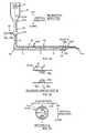
- Fig. 3A shows a vertical sectional view of the polymer discharge tube 41 cut along the central portion thereof.
- Fig. 3B shows an enlarged view of part B in Fig. 3A, and
- Fig. 3C shows a sectional view taken along line C-C of Fig. 3B .
- the polymer discharge tube 41 has a circular pipe (a cylindrical tube whose section is a perfect circle) bended in an L shape, for example, as its main body.
- the polymer discharge tube 41 has a vertical duct portion 42 that has the duct axis oriented in the vertical direction to the MD direction and a horizontal duct portion 43 that has the duct axis oriented in the horizontal direction to the MD direction, and these two are connected by a bend duct 44.
- the aforementioned discharge hole 41a is provided at the tip of the horizontal duct portion 43 whereas a SAP feed mechanism 46 for feeding SAP to the polymer discharge tube 41 is provided at the upper end 42a of the vertical duct portion 42.
- the SAP feed mechanism 46 has, for example, a screw feeder 47 at the upper portion thereof and SAP is volumetrically fed by allowing SAP to drop from the screw feeder 47 to the upper end 42a of the vertical duct portion 42.
- a compressed air injection device 48 is connected at approximately the middle position 42b of this vertical duct portion 42. And compressed air of a predetermined pressure is permanently injected from this compressed air injection device 48 toward the aforementioned discharge hole 41 thereby creating an airflow 6 along the approximately tube axis direction at the portion in the tube on the downstream side of the aforementioned approximately middle position 42b, to allow SAP to flow along this airflow 6 to be discharged through the discharge hole 41a and into the duct 31.
- this compressed air injection device 48 there can be given one that includes a tank, not shown, that stores compressed air, a pipe 48a that connects this tank with the aforementioned vertical duct portion 42, a valve 48b that opens/closes the path of pipe 48a, and a compressor, not shown, that maintains within a predetermined range the pressure value of the compressed air in the aforementioned tank. And feeding of the compressed air into the polymer discharge tube 41 is controlled by controlling opening/closing of the valve 48b appropriately.
- SAP is a particle whose median of its size is 300 to 500 ⁇ m, for example, and its bulk density is for example 0.7 g/ml (700 kg/m 3 ) being relatively heavy. Therefore, when SAP flow along the airflow 6 in the polymer discharge tube 41, they are not transferred in an evenly dispersed state within the section of the plow path of the polymer discharge tube 41 but rather in an uneven state. Thus when discharged into the duct 31 as it is, there is fear that the SAP distribution in the duct 31 will be uneven in the CD direction.
- the forming die 21 of the drum 20 is commonly provided so that the absorbent body 1 to be formed is oriented in the CD direction, and in such a case, the accumulation distribution of SAP in the width direction of the absorbent body 1 would be uneven causing problems in fluid absorbing performance of the absorption article.
- a distribution change area 45 that changes the SAP distribution state is provided to the horizontal duct portion 43 of the polymer discharge tube 41 as shown in Figs. 3A through 3C .
- This distribution change area 45 is provided at a part on the discharge hole 41a side of the path of airflow 6 (the duct path between the aforementioned approximately middle position 42b being the location at which the compressed air injection device 48 is connected and the discharge hole 41a), that is to say, provided at a part closer to the discharge hole 41a than the aforementioned middle position 42b.
- the sectional area of the flow path of this distribution change area 45 is narrower than the sectional area of the flow path of parts 43d, 43e adjacent at the upstream side and the downstream side of the distribution change area 45 as shown in Fig. 3B .
- the SAP distribution state is changed with this.
- the horizontal duct portion 43 of the polymer discharge tube 41 in the examples shown in Figs. 3A to 3C is a circular pipe as described above, and the direction of flow along the flow path of the horizontal duct portion 43 is oriented in the horizontal direction with regard to the MD direction.
- this sectional shape concerned is of a shape line symmetric with regard to the straight line L43 parallel to the aforementioned vertical direction running through the center C43 of the section.
- the central portion in the CD direction is of a constricted shape with the clearance in the vertical direction narrower than the parts at the both sides (two end sides).
- the aspect of changing the sectional area of the distribution change area 45 is not limited to the aspect where a part in the circumferential direction has a locally narrowed sectional shape as shown in Fig. 3C , but includes a case where the shape of the flow path, the shape of this section, is such that the diameter is evenly reduced along the whole circumference in the circumferential direction of the duct.
- the vertical sectional view in Fig. 5A and the sectional view taken along line B-B of Fig. 5A shown in Fig. 5B are also included in the concept of the present invention.
- such aspects can change the SAP distribution state.
- Fig. 5A and the sectional view taken along line B-B of Fig. 5A shown in Fig. 5B are also included in the concept of the present invention.
- such aspects can change the SAP distribution state.
- the distribution change area 45 in the example shown in Figs. 3B and 3C has a pair of hemispherical protrusions 45a, 45b formed to protrude inward in the radial direction from the inner wall face 41s of the polymer discharge tube 41. And one protrusion 45a is formed at the center in the CD direction of the ceiling plane, and another protrusion 45b is formed at the center in the CD direction of the bottom plane.
- the sectional shape of the flow path in the distribution change area 45 has a constricted shape whose clearance in the up-down direction (vertical direction) is widened at both sides than the central portion in the CD direction.
- the sectional shape of the polymer discharge tube 41 is a perfect circle as described above, the amount of SAP distributed in the CD direction before passing through the distribution change area 45 is uneven such that the amount at the center in the CD direction is greater than that on its sides from the first place (see Fig. 4B ) due to the sectional shape of the above-described perfect circular shape. For this reason, when passing this distribution change area 45 such unevenness is set off by the action of the diverted flow created by the sectional shape of the aforementioned distribution change area 45 and as a result, SAP is discharged into the duct 31 in a state with the amount thereof equalized in the CD direction.
- the equalized distribution state is basically maintained and as a result, the SAP accumulation distribution in the CD direction of the absorbent body 1 in the forming die 21 is also equalized. Accordingly, the SAP accumulation distribution in the width direction of the absorbent body 1 can be equalized by designing the position of the forming die 21 so that the CD direction becomes parallel to the width direction of the absorbent body 1.
- protrusions 45a, 45b were provided to the ceiling plane and the bottom plane, respectively, in a manner opposing each other to equalize the accumulation distribution of SAP in the CD direction.
- the location of the protrusions 45a, 45b and their numbers can be appropriately determined according to the individual circumstances of each fiber stacking device 10.
- the protrusions 45a, 45b can be respectively provided on the pair of right and left side faces (the set of faces arranged in the CD direction) of the inner wall face 41s of the polymer discharge tube 41.
- the SAP distribution after passing the distribution change area 45 will be changed to a state where the distribution is dense at the central portion in the CD direction and sparse at the pair of right and left side faces compared to that before passing the distribution change area 45.
- the protrusions 45a, 45b can be provided to only one side face of the two side faces.
- the protrusion 45b can be provided to only one of the ceiling face and the bottom face. And in this case where only one protrusion is provided, the protrusion may be provided on the bottom face as show in Fig. 6B . This is because the SAP distribution in the vertical direction is thought to be uneven such that the amount of SAP in the lower half of the space is greater than that in the upper half of the space. Therefore it is understood that the protrusion 45b provided at the bottom face would be more effective in contributing to separate the SAP flow into the right and left flows in the CD direction.
- the detail conditions such as the height, dimension and shape of the protrusions 45a, 45b are drawn from actual SAP distribution measuring tests and the like conducted with the inner diameter of the polymer discharge tube 41, SAP discharge amount per unit time, amount of airflow per unit time, shape of the discharge hole 41a and the like as parameters.
- the shape of the flow path from this distribution change area 45 to the discharge hole 41a on the downstream side thereof is a shape that is capable of maintaining even SAP distribution in the CD direction.
- Fig. 7 is an example thereof showing a perspective view of a portion proximate the discharge hole 41a of the polymer discharge tube 41 and the flow paths in the examples shown in this Fig. 7 and Fig. 3A have a flattened sectional shape.
- the flow path is formed such that the dimensions in the up-down direction (vertical direction) is reduced stepwise or continuously toward the discharge hole 41a or the dimension in the CD direction is increased stepwise or continuously toward the discharge hole 41a thereby forming the flow path to have an approximately rectangular sectional shape flattened with the dimension in the vertical direction of the flow path being smaller than that in the CD direction.
- the aforementioned discharge hole 41a is provided at the tip thereof. Note that this discharge hole 41a also has a sectional shape flattened in the CD direction, to be specific, the shape of the mouth portion is approximately rectangular with the CD direction as its longitudinal direction.
- the dimension of the discharge hole 41a in the CD direction is equal to or larger than the inner diameter of the polymer discharge tube 41 and equal to or smaller than the dimension of the absorbent body 1 in the CD direction. Further, it is preferable that the dimension of the discharge hole 41a in the up-down direction is such that the area of the discharge hole 41a is equal to or smaller than the sectional area of the polymer discharge tube 41.
- Such shapes of the flow paths with a flattened sectional shape is formed by, for example, collapsing the portion proximate the discharge hole 41 a of the polymer discharge tube 41 in the up-down direction while widening in the CD direction to have a flattened tubular shape (refer to Figs. 7 and 3A ).
- protrusions having hemispherical shapes have been exemplified as the protrusions 45a, 45b provided to the distribution change area 45.
- the shape of the protrusions is not limited to such.
- the shape can be pyramidal or conical such as a triangular pyramid or a circular cone or a unique shape having a plurality of different curved surfaces and planes combined. Note that, when a protrusion in a pyramidal or conical shape is provided, the bottom side of the protrusion can be positioned to face the inner wall face 41s of the polymer discharge tube 41.
- a structure for making the sectional area of the flow path of the distribution change area 45 smaller than the sectional area of the portions 43d, 43e adjacent the upstream side and downstream side thereof is not limited to protrusions 45a, 45b.
- a configuration having a baffle plate 45d formed with through holes 45h, 45h in the thickness direction set to the flow path in the distribution change area 45 may be used.
- a part of the polymer discharge tube 41 may be collapsed to narrow the flow path and be set as the distribution change area 45.
- the polymer discharge tube 41 was configured with a circular pipe having a perfect circular sectional shape.
- the configuration is not limited to such and any configuration can be applied as long as a tubular material is used.
- a pipe whose section is a polygonal shape such as a square pipe or a circular pipe whose section is such as an ellipsoidal shape can be used.
- forming die 21 formed on the outer circumferential face 20a of the rotating drum, and formed to have a depressed shape was shown as an example of the accumulation portion, however, the accumulation portion is not limited to such.
- the outer circumferential face 20a configured to have a generally smooth surface with suction force acting only in this predetermined area of this outer circumferential area 20a can be used to form absorbent bodies 1 by accumulating pulp fibers 2 and SAP at this predetermined area as the aforementioned accumulation portion.
- a chain conveyor or a belt conveyor and the like can be used instead of the rotating drum 20.
- the forming die 21 can be made to travel in a predetermined circumferential orbit with a corresponding conveyor while the aforementioned duct 31 is positioned at a predetermined location along the circumferential orbit.
- pulp fiber 2 (pulp pulverized into fibrous form) was exemplified as liquid absorbent fiber, however, various material used for the absorbent body 1 of absorbent articles such as conventional sanitary napkins, disposable diapers and the like can be used as this liquid absorbent fiber without special requirements.
- cellulosic short fiber such as rayon fiber and cotton fiber
- synthetic short fiber such as polythene fiber and the like can be used. These fibers can be used alone or, two types or more of them combined.
- SAP high-absorbent polymer
- starch-acrylic acid (sodium) grafted copolymer for example, starch-acrylic acid (sodium) grafted copolymer, saponifiable material of starch-acrylonitrile copolymer, cross-linked sodium carboxymethylcellulose, acrylic acid (sodium) copolymer and the like are preferable.
- the above SAP can be used alone or, two types or more of them combined.
- air 3, 6 were exemplified as examples of the first gas and the second gas, however, the gases are not limited to such. That is, as long as gas can be a medium for transferring liquid absorbing fiber and SAP, and does not cause chemical reaction with these liquid absorbing fiber and SAP, the gas need not be air and for example, nitrogen can be used.
- the duct 31 continuous in the vertical direction was positioned above the rotating drum 20, and its distribution mouth 31a made to cover the outer circumferential surface of the rotating drum 20 from above so that the flow path of the airflow 3 including pulp fiber 2 was formed to extend in the vertical direction, however, the positioning is not limited to such.
- a duct 31 continuous in a horizontal or a diagonal direction to the MD direction can be positioned with the flow path of the airflow 3 formed in the horizontal or diagonal direction.
Landscapes
- Health & Medical Sciences (AREA)
- Engineering & Computer Science (AREA)
- Vascular Medicine (AREA)
- Epidemiology (AREA)
- Biomedical Technology (AREA)
- Heart & Thoracic Surgery (AREA)
- Manufacturing & Machinery (AREA)
- Life Sciences & Earth Sciences (AREA)
- Animal Behavior & Ethology (AREA)
- General Health & Medical Sciences (AREA)
- Public Health (AREA)
- Veterinary Medicine (AREA)
- Absorbent Articles And Supports Therefor (AREA)
- Nonwoven Fabrics (AREA)
Abstract


Description
- The present invention relates to a manufacturing device for absorbent bodies relating to absorbent articles such as disposable diapers and the like and a manufacturing method therefor.
- Disposable diapers and sanitary napkins are conventionally known as absorbent articles that absorb fluid such as excreted fluids and the like. This absorbent article includes as a component thereof an absorbent body that absorbs fluid, and has particulate high-absorbent polymer (which is high molecular weight polymer and the like having high fluid retaining performance by swelling and the like due to fluid absorption, and is referred to as SAP hereunder) mixed therein and is produced by forming liquid absorbent fiber such as pulp fibers into a predetermined shape. Note that the absorbent body has a longitudinal direction and a width direction orthogonal to each other and a thickness direction as well. Among these, the width direction is oriented in the width direction of disposable diapers and sanitary napkins.
- Such
absorbent body 1 is for example, formed by accumulating pulp fiber 2 in the airflow 3 flowing through theduct 131 onto theaccumulation portion 121 on the outer circumferential surface of therotating drum 120, as shown in a schematic drawing ofFig. 1A . In other words, theaccumulation portion 121 has multiple air intake holes (not shown) arranged in a predetermined arrangement and the air taken in therethrough makes the pulp fiber 2 accumulate to have a profile approximately the same as that of theaccumulation portion 121 to create theabsorbent body 1. - Additionally, the
duct 131 has apolymer discharge tube 141 disposed thereto and SAP is discharged from thedischarge hole 141a into theduct 131. In this way, SAP also flows along with the airflow 3 in theduct 131 to accumulate on theaccumulation portion 121 with pulp fiber 2. - Here, the SAP and pulp fiber 2 are required to accumulate in a predetermined distribution state in the
absorbent body 1. And SAP, in particular, generally needs to be evenly distributed along the width direction of theabsorbent body 1. - With regard to this point, PTL1 discloses, as a method of distributing SAP evenly, a method of discharging SAP in a distributed manner into the
duct 131 by placing adistribution plate 143 on the outer side of thedischarge hole 141a of thepolymer discharge tube 141 and making SAP flowing along theairflow 6 in theabove discharge tube 141 to collide with thedistribution plate 143. -
- [PTL 1] Japanese Patent Application Laid-open Publication No.
2009-112347 - However, the airflow 3 for allowing the pulp fiber 2 in the
duct 131 to flow would be disturbed by theenergetic airflow 6 distributed after colliding with thedistribution plate 143. For example, in the example shown inFig. 1B , aflow 6a in a direction approximately perpendicular to the duct axis C131 of theduct 131 will be generated and thereby disturbing the airflow 3 along the duct axis C131 of theduct 131. That is, there is fear that the airflow 3 along which pulp fiber 2 flows will be affected by theflow 6a changed for distributing SAP and as a result, the pulp fiber 2 would be unevenly distributed. - The present invention has been made in view of the conventional problems such as those mentioned above, and an object thereof is to provide a manufacturing device and a manufacturing method of an absorbent body capable of changing the high-absorbent polymer distribution state while restricting as much as possible effects on the flow of liquid absorbent fiber such as pulp fiber in a duct.
- In order to solve the above-described problem, a principal aspect of the invention is, a manufacturing device for an absorption body including an accumulation portion that is to have accumulated thereto liquid absorbent fiber in a first gas flowing through a duct, and a polymer discharge tube that is introduced into the duct and that discharges from a discharge hole a second gas having high-absorbent polymer mixed therein toward the accumulation portion, wherein a flow path of the second gas formed in the polymer discharge tube has at a location on the discharge hole side of the flow path a distribution change area where a distribution state of high-absorbent polymer is changed, and a sectional area of the flow path at the distribution change area is narrower than a sectional area of a flow path at a part adjacent on an upstream side as well as a downstream side of the distribution change area.
- And a further aspect of the invention is, a method of manufacturing an absorbent body including accumulating liquid absorbent fiber in a first gas flowing through a duct to an accumulation portion, and discharging from a discharge hole of a polymer discharge tube being introduced into the duct a second gas having high-absorbent polymer mixed therein toward the accumulation portion, wherein a flow path of the second gas formed in the polymer discharge tube has at a location on the discharge hole side of the flow path a distribution change area where a distribution state of high-absorbent polymer is changed, and a sectional area of the flow path at the distribution change area is narrower than a sectional area of a flow path at a part adjacent on an upstream side as well as a downstream side of the distribution change area.
- Features of the invention other than the above will become clear from the description of the present specification and the drawings attached.
- According to the present invention, it is possible to change the distribution state of high-absorbent polymer while restricting as much as possible effects on the flow of liquid absorbent fiber such as pulp fiber in the duct.
-
- [
Fig. 1A] Fig. 1A is a schematic diagram of a conventional manufacturing device forabsorbent bodies 1. - [
Fig. 1B] Fig. 1B is an enlarged view of a portion proximate thedischarge hole 141a of thepolymer discharge tube 141. - [
Fig. 2] Fig. 2 is a schematic diagram of amanufacturing device 10 forabsorbent bodies 1 according to the present embodiment showing a vertical sectional view of themanufacturing device 10 cut along the central portion thereof. - [
Fig. 3A] Fig. 3A is a vertical sectional view of thepolymer discharge tube 41 cut along the central portion thereof. - [
Fig. 3B] Fig. 3B is an enlarged view of part B inFig. 3A . - [
Fig. 3C] Fig. 3C is a sectional view taken along line C-C ofFig. 3B . - [
Fig. 4A] Fig. 4A is an explanatory diagram showing the state of SAP being evenly distributed within the section ofpolymer discharge tube 41. - [
Fig. 4B] Fig. 4B is a graph showing the amount of SAP distributed in the CD direction in an evenly distributed state. - [
Fig. 5A] Fig. 5A is a vertical sectional view of another example of thedistribution change area 45 cut along the central portion thereof. - [
Fig. 5B] Fig. 5B is a sectional view taken along line B-B ofFig. 5A . - [
Fig. 6A] Fig. 6A is a vertical sectional view of another example of thedistribution change area 45. - [
Fig. 6B] Fig. 6B is a vertical sectional view of further another example of thedistribution change area 45. - [
Fig. 7] Fig. 7 is a perspective view of a portion proximate thedischarge hole 41a of thepolymer discharge tube 41. - [
Fig. 8A] Fig. 8A is a vertical sectional view of another example of thedistribution change area 45. - [
Fig. 8B] Fig. 8B is a sectional view taken along line B-B ofFig. 8A . - [
Fig. 9A] Fig. 9A is a vertical sectional view of another example of thedistribution change area 45. - [
Fig. 9B] Fig. 9B is a sectional view taken along line B-B ofFig. 9A . - At least the following matters will be made clear from the description of the present specification with reference to the accompanying drawings.
- A manufacturing device for an absorption body according to the present invention includes an accumulation portion that is to have accumulated thereto liquid absorbent fiber in a first gas flowing through a duct, and a polymer discharge tube that is introduced into the duct and that discharges from a discharge hole a second gas having high-absorbent polymer mixed therein toward the accumulation portion, wherein a flow path of the second gas formed in the polymer discharge tube has at a location on the discharge hole side of the flow path a distribution change area where a distribution state of high-absorbent polymer is changed, and a sectional area of the flow path at the distribution change area is narrower than a sectional area of a flow path at a part adjacent on an upstream side as well as a downstream side of the distribution change area.
- According to such a manufacturing device for absorbent bodies, since the sectional area of the flow path at the distribution change area is small, the distribution of SAP is changed when SAP flows through the corresponding distribution change area and therewith the SAP distribution state in the duct after being discharged from the polymer discharge tube is also changed. As a result, the distribution of SAP accumulated in the absorbent body can be changed.
- Further, the distribution change area is provided in the polymer discharge tube. Therefore, the effects from the changes in the second gas flow when changing the SAP distribution state can be effectively restrained from affecting the first gas flow on the outer side of the polymer discharge tube. In other words, the SAP distribution state can be changed without a significant effect on the flow of liquid absorbent fiber in the duct.
- It is preferable that in the manufacturing device for an absorption body, a section relating to a sectional area of the flow path is an imaginary plane having a direction of flow through the flow path in a normal direction thereof, a shape of the section, when two directions orthogonal to each other and included in the imaginary plane are set as a first direction and a second direction, respectively, is a shape line-symmetric against a straight line parallel to the first direction running through a center of the sectional area, and a sectional shape of a flow path at the distribution change area being such that a clearance in the first direction at the central portion in the second direction is of a constricted shape narrower than parts on two sides of the distribution change area.
- According to such a manufacturing device for absorbent bodies, the SAP distribution state can be changed so that the amount of SAP is reduced at the central portion in the second direction and the amount of SAP is increased on both end sides of the same second direction. In this way, it is possible to handle a phenomenon where the amount of SAP is increased in the central portion of the absorbent body caused by individual circumstances such as the sectional shape of the polymer discharge tube, or cases such as where there is a desire to increase the amount of SAP at the above-mentioned portions on both sides due to the design specification of the absorbent body. By the way, the former phenomenon where the amount of SAP is increased at the central portion of the absorbent body is likely to occur when using as the polymer discharge tube, for example, a tubular material whose flow path has a circular section.
- It is preferable that in the manufacturing device for an absorption body, a sectional shape of a flow path of a part on the discharge hole side than the distribution change area is formed in a shape flattened in the second direction, and the discharge hole has a sectional shape flattened in the second direction.
According to such a manufacturing device for absorbent bodies, both the sectional shape of the flow path at the part on the aforementioned discharge hole side and the form of the aforementioned discharge hole are formed to have a shape flattened in the second direction. Therefore, the SAP distribution state that has been changed by the aforementioned distribution change area can be maintained in also the downstream side of the aforementioned distribution change area. - It is preferable that in the manufacturing device for an absorption body, the flow path of a part on the discharge hole side than the distribution change area is widened in the second direction as approaching the discharge hole.
According to such a manufacturing device for absorbent bodies, the flow path at the part on the aforementioned discharge hole side is widened in the aforementioned second direction so that the SAP distribution state changed by the aforementioned distribution change area can be maintained easier on the downstream side than the aforementioned distribution change area. - It is preferable that in the manufacturing device for an absorption body, a sectional shape of a flow path on an upstream side than the distribution change area is circular, an absorbent body made by accumulating the liquid absorbent fiber and the high-absorbent polymer to the accumulation portion is formed with an accumulation direction set as a thickness direction as well as having a longitudinal direction and a width direction in directions orthogonal to the thickness direction, and the second direction is parallel to the width direction of the absorbent body.
According to such a manufacturing device for absorbent bodies, the phenomenon of the amount of SAP increasing at the central portion in the second direction that may occur due to the circular sectional shape of the flow path on the aforementioned upstream side, is set off by the action of the diverted flow at the aforementioned distribution change area having a constricted part at the center in the second direction. Additionally, the corresponding second direction is parallel to the width direction of the absorbent body. Therefore, an approximately uniform SAP distribution can be realized in the aforementioned width direction. - It is preferable that in the manufacturing device for an absorption body, a pipe with a flow path having a perfect circular sectional shape is used for a part of the flow path that is on an upstream side of the distribution change area.
According to such a manufacturing device for absorbent bodies, a circular pipe being the most generally-used duct material can be applied to the portion on the upstream side of the polymer discharge tube so that a low cost manufacturing device can be realized.
Further, increasing the amount of SAP on both sides in the second direction as well as reducing the amount of SAP at the central portion in the second direction with the aforementioned distribution change area having a constricted part at the central portion in the second direction enables to solve the problem of the amount of SAP increasing at the central portion in the second direction which is likely to occur when the pipe is circular, and thereby SAP distribution in the second direction can be made uniform. - It is preferable that in the manufacturing device for an absorption body, a protrusion protruding from an inner wall face of the polymer discharge tube and being formed at the distribution change area allows to reduce a sectional area of a flow path of the distribution change area.
According to such a manufacturing device for absorbent bodies, the sectional area of the flow path can be reduced just by forming a protrusion in the distribution change area. - Further, a method of manufacturing an absorbent body according to the present invention includes accumulating liquid absorbent fiber in a first gas flowing through a duct to an accumulation portion, and discharging from a discharge hole of a polymer discharge tube being introduced into the duct a second gas having high-absorbent polymer mixed therein toward the accumulation portion, wherein a flow path of the second gas formed in the polymer discharge tube has at a location on the discharge hole side of the flow path a distribution change area where a distribution state of high-absorbent polymer is changed, and a sectional area of the flow path at the distribution change area is narrower than a sectional area of a flow path at a part adjacent on an upstream side as well as a downstream side of the distribution change area.
According to such a manufacturing method for absorbent bodies, operational advantages same as that of the aforementioned manufacturing device for absorbent bodies can be achieved. -
Fig. 2 is a schematic diagram of themanufacturing device 10 ofabsorbent body 1 according to the present embodiment showing a vertical sectional view of themanufacturing device 10 cut along the central portion thereof. - As shown in
Fig. 2 , themanufacturing device 10 forabsorbent bodies 1 according to the present embodiment is a so-calledfiber stacking device 10. In other words, thismanufacturing device 10 includes arotating drum 20 that has provided on the outercircumferential face 20a thereof a forming die 21 (corresponding to the accumulation portion) in a depressed form and that rotates in the circumferential direction Dc, aduct 31 that distributes pulp fiber 2 toward the outercircumferential face 20a of therotating drum 20 to accumulate pulp fiber 2 in the aforementioned formingdie 21 and form theabsorbent body 1, and abelt conveyor 81 that is positioned on the downstream side of the circumferential direction Dc than the location at which theduct 31 is set, to convey theabsorbent body 1 released from the formingdie 21. - Note that in the description below, the circumferential direction Dc of the
rotating drum 20 is also referred to as simply the "circumferential direction Dc" and the width direction of the rotating drum 20 (the direction perpendicular to the plane of the paper inFig. 2 ) is also referred to as the "CD direction" or the "horizontal direction". Additionally, any direction within the plane intersecting this CD direction is also referred to as the "MD direction" and, for example, the aforementioned circumferential direction Dc is a part of the MD direction, the direction of the duct axis ofduct 31 is a part of the MD direction and the duct axis of the later describedpolymer discharge tube 41 is also a part of the MD direction. - The
rotating drum 20 has as its main body, a cylindrical body that rotates by being driven in the clockwise direction as one direction, about for example, a horizontal rotating shaft C20 in the CD direction. And on thecircumferential face 20a thereof,multiple gas inlets 22 are formed at the bottom surface of each forming die 21 provided at a predetermined pitch in the circumferential direction Dc. Therefore, the pulp fibers 2 in theduct 31 flow along the flow 3 of air (corresponding to the first gas) created in theduct 31 by air intake through theaforementioned gas inlets 22, to be distributed and accumulated in the formingdie 21. Therebyabsorbent body 1 is formed in the formingdie 21 with this direction of accumulation as the thickness direction thereof. - Note that, in the circumferential direction Dc, this air intake takes place in the first region R1 where the forming
die 21 opposes theduct 31 but is stopped and does not take place at the second region R2 where the formingdie 21 opposes thebelt conveyor 81. Further, at the latter second region R2, theabsorbent bodies 1 in the forming dies 21 are sequentially released from the forming dies 21 by air suction with thesuction box 83 in thebelt conveyor 81, and in this way theabsorbent bodies 1 are transferred onto thebelt conveyor 81 to be conveyed on thebelt conveyor 81 thereafter. As an example of a configuration that performs air suction there can be given one that includespartition walls rotating drum 20 into zones in the circumferential direction Dc, and a blower, not shown, connected to zone Z1, between the plurality of zones Z1 and Z2, corresponding to the first region R1 at which air suction is to be performed for keeping negative pressure thereat. Note that it is a matter of course that the aforementioned air intake holes 22 of therotating drum 20 and the aforementioned space on the inner circumferential side are in communication allowing air to flow. - Further, as shown in
Fig. 2 ,sheet form members 9 such as non-woven fabric and tissue paper can be fed on thisbelt conveyor 81 for the absorbent bodies to be transferred thereon. And in this case, thesesheet form members 9 become the surface sheet (the sheet that comes into contact with the wearer's skin) relating to disposable diapers and sanitary napkins. - As shown in
Fig. 2 , theduct 31 is for example a tubular member having an approximate rectangular section and is positioned above rotatingdrum 20 with the tube axis direction thereof oriented in the up-down direction (vertical direction) with regard to the MD direction while thedistribution mouth 31a at the bottom end thereof covering over a predetermined area in the circumferential direction Dc above the outercircumferential face 20a of therotating drum 20. Further, pulp fiber 2 made by pulverizingpulp sheet 2s by the pulverizer 35 is fed from themouth 31b at the upper end being an end opposite theaforementioned distribution mouth 31a thereby creating inside theduct 31 an airflow 3 including pulp fibers 2 flowing from the upper side toward the lower side. Therefore,absorbent body 1 is formed by pulp fibers 2 being accumulated in the formingdie 21 when the forming die 21 passes the location of thecorresponding distribution mouth 31a along with the rotation of therotating drum 20. - By the way, this
duct 31 has inserted from the outer side thereof and positioned therein apolymer discharge tube 41 for injecting particulate SAP (high-absorbent polymer). And air 6 (corresponding to the second gas) having SAP mixed therein flows through thispolymer discharge tube 41 along thisairflow 6 for SAP to be discharged from thedischarge hole 41a at the tip end of thepolymer discharge tube 41 into theduct 31. -
Fig. 3A shows a vertical sectional view of thepolymer discharge tube 41 cut along the central portion thereof.Fig. 3B shows an enlarged view of part B inFig. 3A, and Fig. 3C shows a sectional view taken along line C-C ofFig. 3B . - The
polymer discharge tube 41 has a circular pipe (a cylindrical tube whose section is a perfect circle) bended in an L shape, for example, as its main body. Specifically, thepolymer discharge tube 41 has avertical duct portion 42 that has the duct axis oriented in the vertical direction to the MD direction and ahorizontal duct portion 43 that has the duct axis oriented in the horizontal direction to the MD direction, and these two are connected by abend duct 44. Further, theaforementioned discharge hole 41a is provided at the tip of thehorizontal duct portion 43 whereas aSAP feed mechanism 46 for feeding SAP to thepolymer discharge tube 41 is provided at theupper end 42a of thevertical duct portion 42. TheSAP feed mechanism 46 has, for example, ascrew feeder 47 at the upper portion thereof and SAP is volumetrically fed by allowing SAP to drop from thescrew feeder 47 to theupper end 42a of thevertical duct portion 42. Further, a compressedair injection device 48 is connected at approximately themiddle position 42b of thisvertical duct portion 42. And compressed air of a predetermined pressure is permanently injected from this compressedair injection device 48 toward theaforementioned discharge hole 41 thereby creating anairflow 6 along the approximately tube axis direction at the portion in the tube on the downstream side of the aforementioned approximatelymiddle position 42b, to allow SAP to flow along thisairflow 6 to be discharged through thedischarge hole 41a and into theduct 31. - As an example of a configuration of this compressed
air injection device 48, there can be given one that includes a tank, not shown, that stores compressed air, apipe 48a that connects this tank with the aforementionedvertical duct portion 42, avalve 48b that opens/closes the path ofpipe 48a, and a compressor, not shown, that maintains within a predetermined range the pressure value of the compressed air in the aforementioned tank. And feeding of the compressed air into thepolymer discharge tube 41 is controlled by controlling opening/closing of thevalve 48b appropriately. - By the way, SAP is a particle whose median of its size is 300 to 500µm, for example, and its bulk density is for example 0.7 g/ml (700 kg/m3) being relatively heavy. Therefore, when SAP flow along the
airflow 6 in thepolymer discharge tube 41, they are not transferred in an evenly dispersed state within the section of the plow path of thepolymer discharge tube 41 but rather in an uneven state. Thus when discharged into theduct 31 as it is, there is fear that the SAP distribution in theduct 31 will be uneven in the CD direction. Meanwhile, in many cases the forming die 21 of thedrum 20 is commonly provided so that theabsorbent body 1 to be formed is oriented in the CD direction, and in such a case, the accumulation distribution of SAP in the width direction of theabsorbent body 1 would be uneven causing problems in fluid absorbing performance of the absorption article. - Even if SAP were to be evenly distributed within the section of the
polymer discharge tube 41 as shown inFig. 4A , the SAP distribution amount when seen in the CD direction is greater at the middle than the two sides in the CD direction due to the sectional shape of thepolymer discharge tube 41 being a perfect circle. Therefore, when discharged as it is, the distribution would be such that the amount of SAP accumulated at the middle in the CD direction of the formingdie 21 would be greater than that at the two sides. Being the case, equal distribution is prevented with SAP distribution in theabsorbent body 1 being uneven in the width direction. - For this reason, a
distribution change area 45 that changes the SAP distribution state is provided to thehorizontal duct portion 43 of thepolymer discharge tube 41 as shown inFigs. 3A through 3C . Thisdistribution change area 45 is provided at a part on thedischarge hole 41a side of the path of airflow 6 (the duct path between the aforementioned approximatelymiddle position 42b being the location at which the compressedair injection device 48 is connected and thedischarge hole 41a), that is to say, provided at a part closer to thedischarge hole 41a than the aforementionedmiddle position 42b. And the sectional area of the flow path of thisdistribution change area 45 is narrower than the sectional area of the flow path ofparts distribution change area 45 as shown inFig. 3B . And the SAP distribution state is changed with this. - For example, the
horizontal duct portion 43 of thepolymer discharge tube 41 in the examples shown inFigs. 3A to 3C is a circular pipe as described above, and the direction of flow along the flow path of thehorizontal duct portion 43 is oriented in the horizontal direction with regard to the MD direction. Therefore, when the section with regard to the sectional area of this flow path is viewed as an imaginary plane with the direction of flow through the flow path as the normal direction, and two directions, orthogonal to each other as well as included in this imaginary plane, are regarded to be separated in the CD direction (corresponding to the second direction) and the vertical direction (corresponding to the first direction), since the sectional shape of the aforementioned flow path is a perfect circle, this sectional shape concerned is of a shape line symmetric with regard to the straight line L43 parallel to the aforementioned vertical direction running through the center C43 of the section. - And with regard to the sectional shape of the flow path at the
distribution change area 45 in the example shown inFig. 3C , the central portion in the CD direction is of a constricted shape with the clearance in the vertical direction narrower than the parts at the both sides (two end sides). Therewith, when SAP pass through thisdistribution change area 45, the SAP distribution state in the CD direction is changed such that the amount of SAP at the central portion in the CD direction is reduced and that at the parts at the both sides are increased. - Various cases (such as those shown in
Fig. 6A and Fig. 6B ) according to the individual circumstances of thefiber stacking device 10 can be presumed as the above aspects for changing the state of distribution. Provided that thedistribution change area 45 in concern is set in thepolymer discharge tube 41 in all of the aspects for changing the distribution according to the present invention. Therefore, changes in SAP andairflow 6 in thepolymer discharge tube 41 accompanied with the changes in the SAP distribution state can be effectively restrained from affecting the flow of pulp fiber 2 flowing on the outer side of thepolymer discharge tube 41. That is, the SAP distribution state can be changed with the correspondingdistribution change area 45 without having a large effect on the flow of pulp fiber 2 in theduct 31. - By the way, the aspect of changing the sectional area of the
distribution change area 45 is not limited to the aspect where a part in the circumferential direction has a locally narrowed sectional shape as shown inFig. 3C , but includes a case where the shape of the flow path, the shape of this section, is such that the diameter is evenly reduced along the whole circumference in the circumferential direction of the duct. And as shown in the vertical sectional view inFig. 5A and the sectional view taken along line B-B ofFig. 5A shown inFig. 5B are also included in the concept of the present invention. In other words, such aspects can change the SAP distribution state. For example inFig. 5A , even if SAP were to flow in a distribution state with a predetermined unevenness along theflow path 43d at the upstream side than thedistribution change area 45, SAP is forcefully collected to the center by the flow path with a reduced diameter when passing through thisdistribution change area 45. Therefore, when SAP after passing through thisdistribution change area 45 exits to flowpath 43e where the diameter is widened once again, the SAP distribution state will have been changed to a more densely distributed state at the central portion of the section of the flow path. - Hereinafter, specific description on the structure of the
distribution change area 45 will follow. - The
distribution change area 45 in the example shown inFigs. 3B and 3C has a pair ofhemispherical protrusions inner wall face 41s of thepolymer discharge tube 41. And oneprotrusion 45a is formed at the center in the CD direction of the ceiling plane, and anotherprotrusion 45b is formed at the center in the CD direction of the bottom plane. In this way, the sectional shape of the flow path in thedistribution change area 45 has a constricted shape whose clearance in the up-down direction (vertical direction) is widened at both sides than the central portion in the CD direction. - For such reason, when SAP flows along the
airflow 6 through thisdistribution change area 45, theairflow 6 is divided into the left and right flows in the CD direction. And thereby, the SAP distribution state is changed to be sparse at the central portion and dense on the right and left sides thereof, compared to the SAP distribution state before passing through thedistribution change area 45, and thereafter SAP is discharged through thedischarge hole 41a into theduct 31. - Here in this example, since the sectional shape of the
polymer discharge tube 41 is a perfect circle as described above, the amount of SAP distributed in the CD direction before passing through thedistribution change area 45 is uneven such that the amount at the center in the CD direction is greater than that on its sides from the first place (seeFig. 4B ) due to the sectional shape of the above-described perfect circular shape. For this reason, when passing thisdistribution change area 45 such unevenness is set off by the action of the diverted flow created by the sectional shape of the aforementioneddistribution change area 45 and as a result, SAP is discharged into theduct 31 in a state with the amount thereof equalized in the CD direction. The equalized distribution state is basically maintained and as a result, the SAP accumulation distribution in the CD direction of theabsorbent body 1 in the formingdie 21 is also equalized. Accordingly, the SAP accumulation distribution in the width direction of theabsorbent body 1 can be equalized by designing the position of the formingdie 21 so that the CD direction becomes parallel to the width direction of theabsorbent body 1. - Note that, in the example of
Figs. 3B and 3C ,protrusions protrusions fiber stacking device 10. - As shown in the sectional diagram in
Fig. 6A , for example, theprotrusions inner wall face 41s of thepolymer discharge tube 41. In this way, the SAP distribution after passing thedistribution change area 45 will be changed to a state where the distribution is dense at the central portion in the CD direction and sparse at the pair of right and left side faces compared to that before passing thedistribution change area 45. Note that when the SAP distribution is made uneven intentionally in the CD direction, theprotrusions - Alternatively, the
protrusion 45b can be provided to only one of the ceiling face and the bottom face. And in this case where only one protrusion is provided, the protrusion may be provided on the bottom face as show inFig. 6B . This is because the SAP distribution in the vertical direction is thought to be uneven such that the amount of SAP in the lower half of the space is greater than that in the upper half of the space. Therefore it is understood that theprotrusion 45b provided at the bottom face would be more effective in contributing to separate the SAP flow into the right and left flows in the CD direction. - Taking into account the number of the
aforementioned protrusions protrusions polymer discharge tube 41, SAP discharge amount per unit time, amount of airflow per unit time, shape of thedischarge hole 41a and the like as parameters. - By the way, in the examples shown in
Figs. 3A to 3C , it is preferable that the shape of the flow path from thisdistribution change area 45 to thedischarge hole 41a on the downstream side thereof is a shape that is capable of maintaining even SAP distribution in the CD direction.Fig. 7 is an example thereof showing a perspective view of a portion proximate thedischarge hole 41a of thepolymer discharge tube 41 and the flow paths in the examples shown in thisFig. 7 andFig. 3A have a flattened sectional shape. To be more specific, the flow path is formed such that the dimensions in the up-down direction (vertical direction) is reduced stepwise or continuously toward thedischarge hole 41a or the dimension in the CD direction is increased stepwise or continuously toward thedischarge hole 41a thereby forming the flow path to have an approximately rectangular sectional shape flattened with the dimension in the vertical direction of the flow path being smaller than that in the CD direction. And at the tip thereof, theaforementioned discharge hole 41a is provided. Note that thisdischarge hole 41a also has a sectional shape flattened in the CD direction, to be specific, the shape of the mouth portion is approximately rectangular with the CD direction as its longitudinal direction. - Here, it is preferable that the dimension of the
discharge hole 41a in the CD direction is equal to or larger than the inner diameter of thepolymer discharge tube 41 and equal to or smaller than the dimension of theabsorbent body 1 in the CD direction. Further, it is preferable that the dimension of thedischarge hole 41a in the up-down direction is such that the area of thedischarge hole 41a is equal to or smaller than the sectional area of thepolymer discharge tube 41. - Such shapes of the flow paths with a flattened sectional shape is formed by, for example, collapsing the portion proximate the
discharge hole 41 a of thepolymer discharge tube 41 in the up-down direction while widening in the CD direction to have a flattened tubular shape (refer toFigs. 7 and3A ). - Hereinabove, explanation on the embodiments of the present invention have been given, however, the present invention is not limited to such embodiments and modifications such as those in the following can be made.
- In the aforementioned embodiment, as in
Figs. 3B and 3C , protrusions having hemispherical shapes have been exemplified as theprotrusions distribution change area 45. However, the shape of the protrusions is not limited to such. For example, the shape can be pyramidal or conical such as a triangular pyramid or a circular cone or a unique shape having a plurality of different curved surfaces and planes combined. Note that, when a protrusion in a pyramidal or conical shape is provided, the bottom side of the protrusion can be positioned to face theinner wall face 41s of thepolymer discharge tube 41. - Further, as a structure for making the sectional area of the flow path of the
distribution change area 45 smaller than the sectional area of theportions protrusions Fig. 8A and the sectional view taken along line B-B ofFig. 8A inFig. 8B , a configuration having abaffle plate 45d formed with throughholes distribution change area 45 may be used. Moreover, as shown in the vertical sectional view inFig. 9A and the sectional view taken along line B-B ofFig. 9A inFig. 9B , a part of thepolymer discharge tube 41 may be collapsed to narrow the flow path and be set as thedistribution change area 45. - In the aforementioned embodiment, the
polymer discharge tube 41 was configured with a circular pipe having a perfect circular sectional shape. However, the configuration is not limited to such and any configuration can be applied as long as a tubular material is used. For example, a pipe whose section is a polygonal shape such as a square pipe or a circular pipe whose section is such as an ellipsoidal shape can be used. - In the aforementioned embodiment, forming die 21 formed on the outer
circumferential face 20a of the rotating drum, and formed to have a depressed shape was shown as an example of the accumulation portion, however, the accumulation portion is not limited to such. For example, the outercircumferential face 20a configured to have a generally smooth surface with suction force acting only in this predetermined area of this outercircumferential area 20a can be used to formabsorbent bodies 1 by accumulating pulp fibers 2 and SAP at this predetermined area as the aforementioned accumulation portion. Further, a chain conveyor or a belt conveyor and the like can be used instead of therotating drum 20. In other words, the formingdie 21 can be made to travel in a predetermined circumferential orbit with a corresponding conveyor while theaforementioned duct 31 is positioned at a predetermined location along the circumferential orbit. - In the aforementioned embodiment, pulp fiber 2 (pulp pulverized into fibrous form) was exemplified as liquid absorbent fiber, however, various material used for the
absorbent body 1 of absorbent articles such as conventional sanitary napkins, disposable diapers and the like can be used as this liquid absorbent fiber without special requirements. For example, cellulosic short fiber such as rayon fiber and cotton fiber or synthetic short fiber such as polythene fiber and the like can be used. These fibers can be used alone or, two types or more of them combined. - In the aforementioned embodiment, specific examples of high-absorbent polymer (SAP) was not described, however, various material used for the
absorbent body 1 of absorbent articles such as conventional sanitary napkins, disposable diapers and the like can be used as this SAP without special requirements. For example, starch material, cellulosic material, synthetic polymer material and the like can be used. Here, SAP is generally in a particle form. As SAP, it is preferable that it is liquid absorbing and retentive of 20 times or more of its own weight and having a characteristic of gelation as well. For example, starch-acrylic acid (sodium) grafted copolymer, saponifiable material of starch-acrylonitrile copolymer, cross-linked sodium carboxymethylcellulose, acrylic acid (sodium) copolymer and the like are preferable. The above SAP can be used alone or, two types or more of them combined. - In the aforementioned embodiment,
air 3, 6 were exemplified as examples of the first gas and the second gas, however, the gases are not limited to such. That is, as long as gas can be a medium for transferring liquid absorbing fiber and SAP, and does not cause chemical reaction with these liquid absorbing fiber and SAP, the gas need not be air and for example, nitrogen can be used. - In the aforementioned embodiment, the
duct 31 continuous in the vertical direction was positioned above therotating drum 20, and itsdistribution mouth 31a made to cover the outer circumferential surface of therotating drum 20 from above so that the flow path of the airflow 3 including pulp fiber 2 was formed to extend in the vertical direction, however, the positioning is not limited to such. For example, aduct 31 continuous in a horizontal or a diagonal direction to the MD direction can be positioned with the flow path of the airflow 3 formed in the horizontal or diagonal direction. - In the aforementioned embodiment, only one
distribution change area 45 was set in the tube axis direction of thepolymer discharge tube 41, however, it's number is not limited to one and can be set at a plurality of locations along the tube axis direction. -
- 1 absorbent body, 2 pulp fiber (liquid absorbent fiber),
- 2s pulp sheet, 3 airflow (first gas, air),
- 6 airflow (second gas, air), 9 sheet form member,
- 10 fiber stacking device (manufacturing device),
- 20 rotating drum, 20a outer circumferential face,
- 21 forming die (accumulation portion), 22 air intake holes,
- 27a partitioning wall, 27b partitioning wall, 31 duct,
- 31a distribution mouth, 31b mouth at upper end,
- 35 pulverizer, 41 polymer discharge tube, 41a discharge hole,
- 41s inner wall face, 42 vertical duct portion, 42a upper end,
- 42b approximately middle position, 43 horizontal duct portion,
- 43d part adjacent to the upstream side of the distribution change area,
- 43e part adjacent to the downstream side of the distribution change area,
- 44 bend duct, 45 distribution change area, 45a protrusion,
- 45b protrusion, 45d baffle plate, 45h through hole,
- 46 SAP feed mechanism, 47 screw feeder,
- 48 compressed air injection device, 48a pipe, 48b valve,
- 81 belt conveyor, 83 suction box, SAP high-absorbent polymer,
- R1 first region, R2 second region, Z1 zone, Z2 zone,
- C20 rotating shaft, C43 center of section
Claims (8)
- A manufacturing device for an absorption body comprising:an accumulation portion that is to have accumulated thereto liquid absorbent fiber in a first gas flowing through a duct; anda polymer discharge tube that is introduced into the duct and that discharges from a discharge hole a second gas having high-absorbent polymer mixed therein toward the accumulation portion;wherein a flow path of the second gas formed in the polymer discharge tube has at a location on the discharge hole side of the flow path a distribution change area where a distribution state of high-absorbent polymer is changed, and
a sectional area of the flow path at the distribution change area is narrower than a sectional area of a flow path at a part adjacent on an upstream side as well as a downstream side of the distribution change area. - The manufacturing device for an absorption body according to claim 1, wherein
a section relating to a sectional area of the flow path is an imaginary plane having a direction of flow through the flow path in a normal direction thereof,
a shape of the section, when two directions orthogonal to each other and included in the imaginary plane are set as a first direction and a second direction, respectively, is a shape line-symmetric against a straight line parallel to the first direction running through a center of the sectional area, and
a sectional shape of a flow path at the distribution change area being such that a clearance in the first direction at the central portion in the second direction is of a constricted shape narrower than parts on two sides of the distribution change area. - The manufacturing device for an absorption body according to claim 2, wherein
a sectional shape of a flow path of a part on the discharge hole side than the distribution change area is formed in a shape flattened in the second direction, and
the discharge hole has a sectional shape flattened in the second direction. - The manufacturing device for an absorption body according to claim 2 or 3, wherein
the flow path of a part on the discharge hole side than the distribution change area is widened in the second direction as approaching the discharge hole. - The manufacturing device for an absorption body according to one of claims 2 to 4, wherein
a sectional shape of a flow path on an upstream side than the distribution change area is circular,
an absorbent body made by accumulating the liquid absorbent fiber and the high-absorbent polymer to the accumulation portion is formed with an accumulation direction set as a thickness direction as well as having a longitudinal direction and a width direction in directions orthogonal to the thickness direction, and
the second direction is parallel to the width direction of the absorbent body. - The manufacturing device for an absorption body according to one of claims 2 to 5, wherein
a pipe with a flow path having a perfect circular sectional shape is used for a part of the flow path that is on an upstream side of the distribution change area. - The manufacturing device for an absorption body according to one of claims 1 to 6, wherein
a protrusion protruding from an inner wall face of the polymer discharge tube and being formed at the distribution change area allows to reduce a sectional area of a flow path of the distribution change area. - A method of manufacturing an absorbent body comprising:accumulating liquid absorbent fiber in a first gas flowing through a duct to an accumulation portion; anddischarging from a discharge hole of a polymer discharge tube being introduced into the duct a second gas having high-absorbent polymer mixed therein toward the accumulation portion;wherein a flow path of the second gas formed in the polymer discharge tube has at a location on the discharge hole side of the flow path a distribution change area where a distribution state of high-absorbent polymer is changed, and
a sectional area of the flow path at the distribution change area is narrower than a sectional area of a flow path at a part adjacent on an upstream side as well as a downstream side of the distribution change area.
Applications Claiming Priority (2)
| Application Number | Priority Date | Filing Date | Title |
|---|---|---|---|
| JP2009270635A JP5386323B2 (en) | 2009-11-27 | 2009-11-27 | Absorber manufacturing apparatus and manufacturing method |
| PCT/JP2010/068312 WO2011065153A1 (en) | 2009-11-27 | 2010-10-19 | Device and method for manufacturing absorption body |
Publications (2)
| Publication Number | Publication Date |
|---|---|
| EP2505170A1 true EP2505170A1 (en) | 2012-10-03 |
| EP2505170A4 EP2505170A4 (en) | 2014-01-01 |
Family
ID=44066258
Family Applications (1)
| Application Number | Title | Priority Date | Filing Date |
|---|---|---|---|
| EP10833000.2A Withdrawn EP2505170A4 (en) | 2009-11-27 | 2010-10-19 | Device and method for manufacturing absorption body |
Country Status (7)
| Country | Link |
|---|---|
| US (1) | US20120280434A1 (en) |
| EP (1) | EP2505170A4 (en) |
| JP (1) | JP5386323B2 (en) |
| CN (1) | CN102665630B (en) |
| EA (1) | EA201200812A1 (en) |
| TW (1) | TW201138731A (en) |
| WO (1) | WO2011065153A1 (en) |
Cited By (1)
| Publication number | Priority date | Publication date | Assignee | Title |
|---|---|---|---|---|
| EP4378436B1 (en) | 2022-11-29 | 2025-08-27 | Ontex BV | Apparatus for distributing superabsorbent particles onto a substrate |
Families Citing this family (7)
| Publication number | Priority date | Publication date | Assignee | Title |
|---|---|---|---|---|
| CN102389351B (en) * | 2011-08-09 | 2013-09-04 | 李木金 | Absorption core forming device on production line of hygienic products |
| JP6045302B2 (en) * | 2012-10-31 | 2016-12-14 | ユニ・チャーム株式会社 | Method for manufacturing an absorbent for body fluid treatment |
| WO2014104118A1 (en) * | 2012-12-25 | 2014-07-03 | 株式会社瑞光 | Method and device for supplying powder |
| CN203525805U (en) | 2013-09-26 | 2014-04-09 | 株式会社瑞光 | Pulverizer and absorber manufacturing device |
| GB2575216B (en) * | 2017-11-28 | 2022-08-24 | Kao Corp | Method for producing absorber and method for producing absorbent article |
| JP7427922B2 (en) * | 2019-03-20 | 2024-02-06 | セイコーエプソン株式会社 | Defibration processing equipment and fiber processing equipment |
| GB2598253A (en) * | 2019-05-07 | 2022-02-23 | Kimberly Clark Co | Absorbent article |
Family Cites Families (13)
| Publication number | Priority date | Publication date | Assignee | Title |
|---|---|---|---|---|
| US4927582A (en) * | 1986-08-22 | 1990-05-22 | Kimberly-Clark Corporation | Method and apparatus for creating a graduated distribution of granule materials in a fiber mat |
| US5102585A (en) * | 1990-01-09 | 1992-04-07 | Kimberly-Clark Corporation | Method for intermittently depositing particulate material in a substrate |
| US5429788A (en) * | 1994-03-28 | 1995-07-04 | Kimberly-Clark Corporation | Apparatus and method for depositing particulate material in a composite substrate |
| US5558713A (en) * | 1994-10-31 | 1996-09-24 | The Procter & Gamble Company | Method and apparatus for forming a pulsed stream of particles for application to a fibrous web |
| DE69914219T2 (en) * | 1998-10-06 | 2004-06-09 | M & J Fibretech A/S | DEVICE FOR PRODUCING A RIBBON-LIKE FIBER AND POWDER PRODUCT |
| US6207099B1 (en) * | 1999-10-20 | 2001-03-27 | Kimberly-Clark Worldwide, Inc. | Process for uniform cross-direction distribution of particulate material |
| US7303708B2 (en) * | 2004-04-19 | 2007-12-04 | Curt G. Joa, Inc. | Super absorbent distribution system design for homogeneous distribution throughout an absorbent core |
| JP4537174B2 (en) * | 2004-10-20 | 2010-09-01 | 大王製紙株式会社 | Absorber manufacturing equipment |
| JP2008110293A (en) * | 2006-10-30 | 2008-05-15 | Ntn Corp | Aerosol discharge nozzle and filming device |
| JP4711945B2 (en) * | 2006-12-22 | 2011-06-29 | 花王株式会社 | Absorbent manufacturing method and manufacturing apparatus |
| JP5049743B2 (en) * | 2007-11-01 | 2012-10-17 | 花王株式会社 | Deposited body manufacturing method and manufacturing apparatus |
| JP5102582B2 (en) | 2007-11-01 | 2012-12-19 | 花王株式会社 | Absorbent manufacturing method and manufacturing apparatus |
| WO2010031742A1 (en) * | 2008-09-16 | 2010-03-25 | Basf Se | Adjustable solid particle application system |
-
2009
- 2009-11-27 JP JP2009270635A patent/JP5386323B2/en not_active Expired - Fee Related
-
2010
- 2010-10-19 US US13/511,739 patent/US20120280434A1/en not_active Abandoned
- 2010-10-19 CN CN201080053348.7A patent/CN102665630B/en not_active Expired - Fee Related
- 2010-10-19 EP EP10833000.2A patent/EP2505170A4/en not_active Withdrawn
- 2010-10-19 WO PCT/JP2010/068312 patent/WO2011065153A1/en not_active Ceased
- 2010-10-19 EA EA201200812A patent/EA201200812A1/en unknown
- 2010-11-26 TW TW099141033A patent/TW201138731A/en unknown
Cited By (1)
| Publication number | Priority date | Publication date | Assignee | Title |
|---|---|---|---|---|
| EP4378436B1 (en) | 2022-11-29 | 2025-08-27 | Ontex BV | Apparatus for distributing superabsorbent particles onto a substrate |
Also Published As
| Publication number | Publication date |
|---|---|
| CN102665630A (en) | 2012-09-12 |
| JP2011110288A (en) | 2011-06-09 |
| EA201200812A1 (en) | 2012-11-30 |
| EP2505170A4 (en) | 2014-01-01 |
| US20120280434A1 (en) | 2012-11-08 |
| TW201138731A (en) | 2011-11-16 |
| JP5386323B2 (en) | 2014-01-15 |
| CN102665630B (en) | 2014-10-15 |
| WO2011065153A1 (en) | 2011-06-03 |
Similar Documents
| Publication | Publication Date | Title |
|---|---|---|
| US20120280434A1 (en) | Manufacturing device for absorbent body and manufacturing method therefor | |
| US9060898B2 (en) | Manufacturing device for absorbent body and manufacturing method therefor | |
| US11141320B2 (en) | Absorbent cores and methods for forming absorbent cores | |
| CN105813609B (en) | Absorbent Manufacturing Equipment | |
| CN105007873B (en) | Absorbent Manufacturing Equipment | |
| CN101977578B (en) | Apparatus and method for producing absorbent body | |
| US20200289335A1 (en) | Absorbent cores and methods for forming absorbent cores | |
| JP5401375B2 (en) | Absorber manufacturing apparatus and manufacturing method | |
| JP4711945B2 (en) | Absorbent manufacturing method and manufacturing apparatus | |
| JP5475434B2 (en) | Absorbent manufacturing method and manufacturing apparatus | |
| KR102615974B1 (en) | Absorbent core and method for forming the absorbent core | |
| US20090081362A1 (en) | Apparatus and method for distributing particulate material onto a moving web | |
| WO2020039534A1 (en) | Spread tow molding device and spread tow production apparatus | |
| JP5836098B2 (en) | Absorber manufacturing equipment |
Legal Events
| Date | Code | Title | Description |
|---|---|---|---|
| PUAI | Public reference made under article 153(3) epc to a published international application that has entered the european phase |
Free format text: ORIGINAL CODE: 0009012 |
|
| 17P | Request for examination filed |
Effective date: 20120601 |
|
| AK | Designated contracting states |
Kind code of ref document: A1 Designated state(s): AL AT BE BG CH CY CZ DE DK EE ES FI FR GB GR HR HU IE IS IT LI LT LU LV MC MK MT NL NO PL PT RO RS SE SI SK SM TR |
|
| DAX | Request for extension of the european patent (deleted) | ||
| A4 | Supplementary search report drawn up and despatched |
Effective date: 20131129 |
|
| RIC1 | Information provided on ipc code assigned before grant |
Ipc: A61F 13/49 20060101ALI20131125BHEP Ipc: A61F 13/472 20060101ALI20131125BHEP Ipc: A61F 13/15 20060101AFI20131125BHEP |
|
| STAA | Information on the status of an ep patent application or granted ep patent |
Free format text: STATUS: THE APPLICATION HAS BEEN WITHDRAWN |
|
| 18W | Application withdrawn |
Effective date: 20140310 |