EP2504497B1 - Compression ou détente de gaz humide centrifuge avec un suppresseur et/ou un pulvérisateur de grumeaux - Google Patents
Compression ou détente de gaz humide centrifuge avec un suppresseur et/ou un pulvérisateur de grumeaux Download PDFInfo
- Publication number
- EP2504497B1 EP2504497B1 EP10833743.7A EP10833743A EP2504497B1 EP 2504497 B1 EP2504497 B1 EP 2504497B1 EP 10833743 A EP10833743 A EP 10833743A EP 2504497 B1 EP2504497 B1 EP 2504497B1
- Authority
- EP
- European Patent Office
- Prior art keywords
- chamber
- compressor
- conduit
- liquid
- gas
- Prior art date
- Legal status (The legal status is an assumption and is not a legal conclusion. Google has not performed a legal analysis and makes no representation as to the accuracy of the status listed.)
- Active
Links
- 230000006835 compression Effects 0.000 title description 4
- 238000007906 compression Methods 0.000 title description 4
- 239000007788 liquid Substances 0.000 claims description 47
- 239000012530 fluid Substances 0.000 claims description 38
- 238000000034 method Methods 0.000 claims description 15
- 230000005574 cross-species transmission Effects 0.000 claims description 3
- 238000005259 measurement Methods 0.000 claims 1
- 230000008569 process Effects 0.000 description 9
- 239000000203 mixture Substances 0.000 description 6
- 241000237858 Gastropoda Species 0.000 description 3
- 230000008859 change Effects 0.000 description 3
- 238000013461 design Methods 0.000 description 3
- 238000010586 diagram Methods 0.000 description 3
- 230000003628 erosive effect Effects 0.000 description 3
- 238000012545 processing Methods 0.000 description 3
- XLYOFNOQVPJJNP-UHFFFAOYSA-N water Substances O XLYOFNOQVPJJNP-UHFFFAOYSA-N 0.000 description 3
- 230000018044 dehydration Effects 0.000 description 2
- 238000006297 dehydration reaction Methods 0.000 description 2
- 238000005516 engineering process Methods 0.000 description 2
- 230000007246 mechanism Effects 0.000 description 2
- 239000003595 mist Substances 0.000 description 2
- 230000004048 modification Effects 0.000 description 2
- 238000012986 modification Methods 0.000 description 2
- 230000009467 reduction Effects 0.000 description 2
- 239000007921 spray Substances 0.000 description 2
- 238000011144 upstream manufacturing Methods 0.000 description 2
- 241001668938 Grapevine virus F Species 0.000 description 1
- 230000004075 alteration Effects 0.000 description 1
- 238000010276 construction Methods 0.000 description 1
- 238000011143 downstream manufacturing Methods 0.000 description 1
- 230000000694 effects Effects 0.000 description 1
- 239000003897 fog Substances 0.000 description 1
- 238000012423 maintenance Methods 0.000 description 1
- 239000000463 material Substances 0.000 description 1
- 230000008520 organization Effects 0.000 description 1
- 239000002245 particle Substances 0.000 description 1
- 238000000926 separation method Methods 0.000 description 1
- 230000009528 severe injury Effects 0.000 description 1
- 238000009491 slugging Methods 0.000 description 1
- 238000012360 testing method Methods 0.000 description 1
- 238000005406 washing Methods 0.000 description 1
Images


Classifications
-
- F—MECHANICAL ENGINEERING; LIGHTING; HEATING; WEAPONS; BLASTING
- F04—POSITIVE - DISPLACEMENT MACHINES FOR LIQUIDS; PUMPS FOR LIQUIDS OR ELASTIC FLUIDS
- F04D—NON-POSITIVE-DISPLACEMENT PUMPS
- F04D29/00—Details, component parts, or accessories
- F04D29/58—Cooling; Heating; Diminishing heat transfer
- F04D29/582—Cooling; Heating; Diminishing heat transfer specially adapted for elastic fluid pumps
- F04D29/5846—Cooling; Heating; Diminishing heat transfer specially adapted for elastic fluid pumps cooling by injection
-
- F—MECHANICAL ENGINEERING; LIGHTING; HEATING; WEAPONS; BLASTING
- F04—POSITIVE - DISPLACEMENT MACHINES FOR LIQUIDS; PUMPS FOR LIQUIDS OR ELASTIC FLUIDS
- F04D—NON-POSITIVE-DISPLACEMENT PUMPS
- F04D31/00—Pumping liquids and elastic fluids at the same time
Definitions
- the subject matter disclosed in this application relates to technology utilized in the compression or expansion of a multiphase fluid in a fluid handling system.
- centrifugal compressors or gas expanders do not handle liquid slugs and thus it is assumed that they can only handle a fraction of one percent liquid by volume.
- expensive liquid separators, dehydration processes and/or unit scrubbers are utilized to try and remove or separate the liquids prior to using centrifugal compressors or expanders.
- These devices are often designed for specific operating conditions and are then limited in the range of Gas Volume Fraction (GVF) that can be handled with a given process flow rate.
- GVF Gas Volume Fraction
- multiphase pumps can be used if it is known that the fluid will generally be below 90% GVF.
- Centrifugal compressors are often restricted to applications with GVFs of 99.7 or higher and even this can cause problems within the machine for stability and affecting the reliability of the seals and bearings. Therefore, for processes outside this small range, the current practice is to separate the fluids prior to utilizing a centrifugal compressor even with the design limitation with the associated process and equipment.
- gas expanders which are functionally a centrifugal compressor running in reverse to extract energy in one form or another through a process pressure drop across the expander.
- the separators, scrubbers and dehydration units are not only expensive and limited in liquid capacity and volume flow range but they also tend to be very bulky, taking up expensive real estate in locations such as offshore platforms, subsea processing or onshore facilities.
- This coupled with complex control systems and additional auxiliary equipment like pumps, regulators, level controllers, transmitters and filters adds to the complexity and likelihood of failure of these systems.
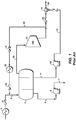
- FIG. 1 depicts a typical oil or gas well stream service where a separator 4 is used to separate liquids from the gas so that a centrifugal compressor 21 and pump 12 can then be used to boost the gas and liquid separately.
- the two are then combined again at 14 in order to transport both through a pipeline to a processing facility. If one machine could be used to transport the combined flow it has the potential to greatly reduce the overall cost and complexity of the total system.
- WO 86/0557 A1 relates to a pump or compressor unit suited particularly for mixed phase fluids, e.g. mixed gas and oil, has a multistage axial flow compressor device with contra-rotating vanes.
- WO 2005/026497 A1 relates to a subsea compression system and method wherein a wellstream fluid is flowed through a flow line from a reservoir and into a separation vessel for subsequent compression in a compressor prior to export of gas.
- the above noted problems in handling multiphase fluid flow have been addressed by utilizing a liquid slug suppressor and/or an atomizing device to enhance the upstream mixing of the liquid with the gas, thus enabling the centrifugal compressor or expander to better handle higher levels of liquid.
- the atomizing device may be any one of known fluid atomizers including one or more atomizing nozzles or a flow mixer device. This can be used in existing designs to help protect the compressor or expander from process upsets with additional liquid volume or as a stand alone design to help eliminate some of the required equipment such as the separator or liquid pump.
- the slug suppressor slows down a slug of liquid and mixes it with gas already in the device to reduce the sudden change in density. This allows time for the compressor driver to slow down as the torque or load increases with the increase in liquid volume or reduction of GVF.
- the atomizing device further helps turn liquid slugs into droplets or mist mixed in with the gas to better help the compressor in dealing with the change in density and load while reducing the impact, resulting in less erosion. Either product or both in series can be used in a compressor or expander application where there is a potential for some liquids or liquid upsets.
- atomizing device means any device or mechanism for breaking a liquid into a fog, mist, or spray of liquid.
- atomized as used herein is to be understood to mean small, discrete particles of liquid.
- slug suppressor means any device that helps slow down the sudden change in fluid density of a high level of liquid within a gas stream by mixing the predominately liquid flow with gas that was flowing ahead of, with or behind the liquid.
- FIG. 1 illustrates a known system for handling a multiphase fluid in a well head environment.
- Fluid which may include water, oil, and gas for example, is directed into a cooler 1 and then into a separator tank 4 via a check valve 2 and conduit 3.
- Water is separated out and a pump 6 pumps the water to a remote location via conduit 7.
- Oil and condensate are collected and pump 12 delivers the oil and condensate to conduit 15 via conduits 11 and 13.
- a recycle line 30 is provided which includes valve 31, cooler 32 and check valve 33.
- Multiphase fluid for example fluid from a well head
- the apparatus by a conduit 50, check valve 51, and conduit 52.
- the mixture of liquid and gas enters a fluid treatment device 55.
- the fluid treatment device may be a slug suppressor or a known atomizing device, such as one or more atomizing nozzles or a flow mixer. It may also be a combination of these elements.
- An example of a combined slug suppressor and atomizing device is shown in FIG. 4 . Liquid accumulates in inner chamber 107 and gas flows in outer chamber 108.
- Baffles 104 are provided in the walls of inner chamber 107 to allow for sudden increases in liquid to spill over into the gas stream and mix with the gas. Thus a sudden increase in liquid flow is slowed down by using some of the gas still in the slug suppressor to reduce the liquid volume.
- Atomizing nozzles 105 at the lower end of the liquid chamber atomize the liquid and spray it into the gas flow downstream of a tapered portion 109 of the gas flow path. The atomized liquid and gas streams continue to flow through conduit portion 106.
- a typical slug suppressor and atomizing device is available from Framo Engineering AS.
- a flow mixer may include counter swirling vanes or counter rotating vortices.
- the mixture leaving the fluid treatment device 55 flows through conduit 56 to compressor 58.
- Compressed fluid leaves compressor 58 through conduit 60 and 61 to check valve 62 and to a distribution conduit 63 which delivers the compressed fluid to a desired location.
- a recycle line for the mixture from compressor 58 is provided at 66 that includes a valve 67, and check valve 69.
- FIG. 3 illustrates the application of the principles of the invention in an expander system.
- a multiphase fluid passes through a multiphase flow meter 82, a control valve 84, and a conduit 85 into the fluid treatment device 55. From there the mixture flows through conduit 91, expander 93, conduit 94, check valve 95 and distribution conduit 96.
- the expander 93 may be connected to a generator or compressor 92 or any device that requires a source of power.
- a bypass line 99, 97 along with a valve 98 are provided for bypassing expander 93.
- a hydraulic torque converter 90 may be positioned between the expander 93 and generator or compressor 90.
- a variable speed drive 57 such as a motor or other mechanical or electrical drive, including but not limited to gas motor, steam or gas turbine, expander, hydraulic turbine, is connected to the compressor 58.
- the drive mechanism controlling the torque or speed between the driver and compressor may be electronic, hydraulic, or mechanical. Suitable means for controlling the variable speed drive may include sensors for sensing torque, load, fluid density, GVF or input power.
- Speed or torque control helps make centrifugal compressors and expanders more robust, thus increasing reliability and reducing maintenance cost in wet services by designing the system to better manage a liquid slug and multiphase flow. This could be applied in all types of centrifugal compressor and expander applications where liquids are present or potentially present in the process, including well head services, subsea compressors or expanders, LNG expansion, wet gas compressors and other upstream and downstream processes.
- the flow control could use a two-or three-phase flow meter 82 to operate an inlet flow valve 84 or inlet guide vanes in order to reduce the flow as the GVF drops with increased liquid level, as shown in FIG 3 .
- Other options are to use a hydraulic torque converter 90 between the gas expander 93 and what it is driving or any other method to measure the fluid density, multiphase flow mixture, mass flow, output power, or torque.
- variable speed drive 57 of FIG. 2 may be replaced by a fixed speed driver 102.
- a hydraulic torque converter 101 may be positioned between the fixed speed driver and the compressor 58 to allow for varying the speed of compressor 58.
Claims (10)
- Appareil de compression d'un fluide polyphasique comprenant :un premier conduit (50) pour acheminer le fluide polyphasique ;un suppresseur de bouchons relié au premier conduit (50) ;un compresseur centrifuge (58) relié à une sortie du suppresseur de bouchons ; etun conduit de distribution (63) relié au compresseur (58) pour acheminer le fluide polyphasique comprimé vers un emplacement souhaité,l'appareil étant caractérisé en ce qu'il comprend en outre un dispositif de pulvérisation positionné dans le premier conduit (50) ;dans lequel le suppresseur de bouchons et le dispositif de pulvérisation sont combinés dans un boîtier ayant une entrée et une sortie, où le boîtier comprendune première chambre (107) pour accumuler un liquide ;une deuxième chambre (108) pour accumuler un gaz ;une pluralité de déflecteurs (104) entre les première et deuxième chambres (107, 108) pour permettre au liquide accumulé dans la première chambre (107) de déborder dans la deuxième chambre (108) ; etune pluralité de buses de pulvérisation (105) situées au niveau de la partie d'extrémité de la première chambre (107).
- Appareil de la revendication 1, dans lequel le dispositif de pulvérisation est un mélangeur continu à courant qui comporte au moins deux aubes à tourbillonnements inverses ou tourbillons contrarotatifs.
- Appareil de la revendication 1, comprenant en outre un variateur de vitesse (57) relié à un arbre d'entrée de puissance du compresseur.
- Appareil selon la revendication 1, dans lequel le boîtier s'effile depuis l'entrée vers la sortie.
- Appareil selon la revendication 1, comprenant en outre un conduit de recyclage (66) relié au niveau d'une extrémité à la sortie du compresseur (58) et au niveau de son autre extrémité au premier conduit (50).
- Appareil selon la revendication 5, comprenant en outre une soupape de recyclage (67, 69) dans le conduit de recyclage (66).
- Procédé de compression d'un fluide polyphasique comprenant les étapes consistant à :fournir un suppresseur de bouchons et un dispositif de pulvérisation,dans lequel le suppresseur de bouchons et le dispositif de pulvérisation sont combinés dans un boîtier ayant une entrée et une sortie, où le boîtier comprendune première chambre (107) pour accumuler un liquide ;une deuxième chambre (108) pour accumuler un gaz ;une pluralité de déflecteurs (104) entre les première et deuxième chambres (107, 108) pour permettre au liquide accumulé dans la première chambre (107) de déborder dans la deuxième chambre (108) ; etune pluralité de buses de pulvérisation (105) situées au niveau de la partie d'extrémité de la première chambre (107) ;diriger un écoulement de fluide polyphasique dans le suppresseur de bouchons et le dispositif de pulvérisation ;diriger l'écoulement de sortie depuis le suppresseur de bouchons et le dispositif de pulvérisation dans une partie d'admission d'un compresseur centrifuge (58) ; etcomprimer le fluide polyphasique.
- Procédé de la revendication 7, comprenant en outre l'étape consistant à :
diriger le fluide polyphasique à travers un mélangeur continu à courant avant qu'il ne soit comprimé. - Procédé de la revendication 7, comprenant en outre l'étape consistant à :
utiliser un moteur électrique ou à gaz, une turbine à gaz ou à vapeur, un détenteur, une turbine hydraulique ou un autre dispositif d'entraînement pour fournir de la puissance au compresseur (58). - Appareil de la revendication 1, comprenant en outre un moyen pour réguler la vitesse du compresseur sur la base d'un couple produit, d'une charge, d'une densité de fluide, d'une mesure d'écoulement polyphasique ou d'une puissance de sortie.
Applications Claiming Priority (2)
| Application Number | Priority Date | Filing Date | Title |
|---|---|---|---|
| US26441409P | 2009-11-25 | 2009-11-25 | |
| PCT/US2010/053774 WO2011066050A1 (fr) | 2009-11-25 | 2010-10-22 | Compression ou détente de gaz humide centrifuge avec un suppresseur et/ou un pulvérisateur de grumeaux |
Publications (3)
| Publication Number | Publication Date |
|---|---|
| EP2504497A1 EP2504497A1 (fr) | 2012-10-03 |
| EP2504497A4 EP2504497A4 (fr) | 2018-04-18 |
| EP2504497B1 true EP2504497B1 (fr) | 2019-05-22 |
Family
ID=44066848
Family Applications (1)
| Application Number | Title | Priority Date | Filing Date |
|---|---|---|---|
| EP10833743.7A Active EP2504497B1 (fr) | 2009-11-25 | 2010-10-22 | Compression ou détente de gaz humide centrifuge avec un suppresseur et/ou un pulvérisateur de grumeaux |
Country Status (10)
| Country | Link |
|---|---|
| US (1) | US20120224980A1 (fr) |
| EP (1) | EP2504497B1 (fr) |
| JP (1) | JP5763667B2 (fr) |
| CN (1) | CN102667017B (fr) |
| AU (1) | AU2010325127B2 (fr) |
| BR (1) | BR112012012489B1 (fr) |
| CA (1) | CA2777868C (fr) |
| RU (1) | RU2552083C2 (fr) |
| SG (1) | SG10201407025TA (fr) |
| WO (1) | WO2011066050A1 (fr) |
Families Citing this family (19)
| Publication number | Priority date | Publication date | Assignee | Title |
|---|---|---|---|---|
| GB2493749B (en) * | 2011-08-17 | 2016-04-13 | Statoil Petroleum As | Improvements relating to subsea compression |
| US9303658B2 (en) * | 2011-11-08 | 2016-04-05 | Dresser-Rand Company | Compact turbomachine system with improved slug flow handling |
| US9915134B2 (en) | 2013-06-24 | 2018-03-13 | Saudi Arabian Oil Company | Integrated pump and compressor and method of producing multiphase well fluid downhole and at surface |
| US10215184B2 (en) | 2015-03-26 | 2019-02-26 | Exxonmobil Upstream Research Company | Controlling a wet gas compression system |
| EP3274593B1 (fr) * | 2015-03-26 | 2021-03-24 | ExxonMobil Upstream Research Company | Compression de gaz humide |
| JP6499500B2 (ja) * | 2015-04-20 | 2019-04-10 | 株式会社日立製作所 | ダウンホール圧縮装置 |
| NO339899B1 (en) * | 2015-05-14 | 2017-02-13 | Vetco Gray Scandinavia As | A control system for controlling a subsea gas compression system |
| WO2016206761A1 (fr) * | 2015-06-26 | 2016-12-29 | Statoil Petroleum As | Détermination de la composition de phase d'un écoulement de fluide |
| GB2558662B (en) | 2017-01-17 | 2021-11-24 | Equinor Energy As | Gas compressor cleaning |
| GB201705517D0 (en) | 2017-04-05 | 2017-05-17 | Statoil Petroleum As | Fluid flow conditioning |
| GB2584079B (en) * | 2019-05-13 | 2022-02-09 | Equinor Energy As | A method and system for preparing a fluid produced at an offshore production facility for transportation |
| US11371326B2 (en) | 2020-06-01 | 2022-06-28 | Saudi Arabian Oil Company | Downhole pump with switched reluctance motor |
| US11499563B2 (en) | 2020-08-24 | 2022-11-15 | Saudi Arabian Oil Company | Self-balancing thrust disk |
| US11920469B2 (en) | 2020-09-08 | 2024-03-05 | Saudi Arabian Oil Company | Determining fluid parameters |
| US11644351B2 (en) | 2021-03-19 | 2023-05-09 | Saudi Arabian Oil Company | Multiphase flow and salinity meter with dual opposite handed helical resonators |
| US11591899B2 (en) | 2021-04-05 | 2023-02-28 | Saudi Arabian Oil Company | Wellbore density meter using a rotor and diffuser |
| US11913464B2 (en) | 2021-04-15 | 2024-02-27 | Saudi Arabian Oil Company | Lubricating an electric submersible pump |
| FR3126423A1 (fr) * | 2021-08-26 | 2023-03-03 | IFP Energies Nouvelles | Procédé d’hydroconversion de charges hydrocarbonées |
| US20230191311A1 (en) * | 2021-12-22 | 2023-06-22 | Uop Llc | Processes and apparatuses for operating a gas compressor |
Family Cites Families (23)
| Publication number | Priority date | Publication date | Assignee | Title |
|---|---|---|---|---|
| USRE20885E (en) * | 1938-10-18 | Uquid separating device | ||
| US2940338A (en) * | 1951-06-14 | 1960-06-14 | Garrett Corp | Variable speed drive |
| US3228858A (en) * | 1962-06-06 | 1966-01-11 | Phillips Petroleum Co | Hydrogenation unit trim control system |
| US4079436A (en) * | 1976-06-28 | 1978-03-14 | Facet Enterprises, Inc. | 5,000 Hour blocking oscillator for an electromagnetic fuel pump |
| US4251236A (en) * | 1977-11-17 | 1981-02-17 | Ciba-Geigy Corporation | Process for purifying the off-gases from industrial furnaces, especially from waste incineration plants |
| US4275988A (en) * | 1978-12-18 | 1981-06-30 | Kalashnikov L F | Axial or worm-type centrifugal impeller pump |
| US4449888A (en) * | 1982-04-23 | 1984-05-22 | Balje Otto E | Free spool inducer pump |
| EP0188543A1 (fr) | 1984-07-13 | 1986-07-30 | AT&T Corp. | Dispositif de manipulation d'articles |
| GB8507010D0 (en) * | 1985-03-19 | 1985-04-24 | Framo Dev Ltd | Compressor unit |
| US5232475A (en) * | 1992-08-24 | 1993-08-03 | Ohio University | Slug flow eliminator and separator |
| US5453471B1 (en) * | 1994-08-02 | 1999-02-09 | Carbide Chemicals & Plastics T | Gas phase polymerization process |
| JP2877098B2 (ja) * | 1995-12-28 | 1999-03-31 | 株式会社日立製作所 | ガスタービン,コンバインドサイクルプラント及び圧縮機 |
| US5864770A (en) * | 1996-03-14 | 1999-01-26 | Ziph; Benjamin | Speed and power control of an engine by modulation of the load torque |
| US6164308A (en) * | 1998-08-28 | 2000-12-26 | Butler; Bryan V. | System and method for handling multiphase flow |
| TW486380B (en) * | 1999-04-19 | 2002-05-11 | Koch Glitsch Inc | Vortex static mixer and method employing same |
| MY123548A (en) * | 1999-11-08 | 2006-05-31 | Shell Int Research | Method and system for suppressing and controlling slug flow in a multi-phase fluid stream |
| US6394764B1 (en) * | 2000-03-30 | 2002-05-28 | Dresser-Rand Company | Gas compression system and method utilizing gas seal control |
| JP2002227657A (ja) * | 2001-02-02 | 2002-08-14 | Takeshi Hatanaka | 水素エンジン、動力システムおよびこれにより駆動される車両 |
| GB2399864A (en) * | 2003-03-22 | 2004-09-29 | Ellastar Ltd | A system and process for pumping multiphase fluids |
| NO321304B1 (no) * | 2003-09-12 | 2006-04-24 | Kvaerner Oilfield Prod As | Undervanns kompressorstasjon |
| EP1747055A4 (fr) * | 2004-04-09 | 2007-08-15 | Turbosonic Inc | Controle de pollution dans un sechoir de produits en bois |
| FR2899288B1 (fr) * | 2006-03-30 | 2008-06-13 | Total Sa | Procede et dispositif pour la compression d'un fluide multiphasique |
| US7569097B2 (en) * | 2006-05-26 | 2009-08-04 | Curtiss-Wright Electro-Mechanical Corporation | Subsea multiphase pumping systems |
-
2010
- 2010-10-22 AU AU2010325127A patent/AU2010325127B2/en active Active
- 2010-10-22 EP EP10833743.7A patent/EP2504497B1/fr active Active
- 2010-10-22 CA CA2777868A patent/CA2777868C/fr active Active
- 2010-10-22 JP JP2012541083A patent/JP5763667B2/ja active Active
- 2010-10-22 BR BR112012012489-7A patent/BR112012012489B1/pt active IP Right Grant
- 2010-10-22 SG SG10201407025TA patent/SG10201407025TA/en unknown
- 2010-10-22 US US13/500,534 patent/US20120224980A1/en not_active Abandoned
- 2010-10-22 RU RU2012126170/13A patent/RU2552083C2/ru not_active IP Right Cessation
- 2010-10-22 CN CN201080053215.XA patent/CN102667017B/zh not_active Expired - Fee Related
- 2010-10-22 WO PCT/US2010/053774 patent/WO2011066050A1/fr active Application Filing
Also Published As
| Publication number | Publication date |
|---|---|
| CN102667017B (zh) | 2015-08-19 |
| EP2504497A4 (fr) | 2018-04-18 |
| RU2552083C2 (ru) | 2015-06-10 |
| BR112012012489B1 (pt) | 2021-06-29 |
| AU2010325127B2 (en) | 2016-04-28 |
| WO2011066050A1 (fr) | 2011-06-03 |
| CN102667017A (zh) | 2012-09-12 |
| AU2010325127A1 (en) | 2012-06-07 |
| CA2777868C (fr) | 2018-07-31 |
| RU2012126170A (ru) | 2013-12-27 |
| SG10201407025TA (en) | 2014-12-30 |
| CA2777868A1 (fr) | 2011-06-03 |
| EP2504497A1 (fr) | 2012-10-03 |
| JP2013512089A (ja) | 2013-04-11 |
| US20120224980A1 (en) | 2012-09-06 |
| JP5763667B2 (ja) | 2015-08-12 |
| BR112012012489A2 (pt) | 2020-08-11 |
Similar Documents
| Publication | Publication Date | Title |
|---|---|---|
| EP2504497B1 (fr) | Compression ou détente de gaz humide centrifuge avec un suppresseur et/ou un pulvérisateur de grumeaux | |
| US10578110B2 (en) | Centrifugal pump with coalescing effect, design method and use thereof | |
| US20150315884A1 (en) | Multiphase pressure boosting pump | |
| GB2337561A (en) | Combined separator, compressor, and liquid pump for multi-phase fluids | |
| GB2339452A (en) | Wet gas compression device having liquid/gas separation features | |
| CA2972928C (fr) | Compression de gaz humide | |
| AU2018271401B2 (en) | Method of controlling a compressor system and compressor system |
Legal Events
| Date | Code | Title | Description |
|---|---|---|---|
| PUAI | Public reference made under article 153(3) epc to a published international application that has entered the european phase |
Free format text: ORIGINAL CODE: 0009012 |
|
| 17P | Request for examination filed |
Effective date: 20120615 |
|
| AK | Designated contracting states |
Kind code of ref document: A1 Designated state(s): AL AT BE BG CH CY CZ DE DK EE ES FI FR GB GR HR HU IE IS IT LI LT LU LV MC MK MT NL NO PL PT RO RS SE SI SK SM TR |
|
| DAX | Request for extension of the european patent (deleted) | ||
| RAP1 | Party data changed (applicant data changed or rights of an application transferred) |
Owner name: EXXONMOBIL UPSTREAM RESEARCH COMPANY |
|
| RA4 | Supplementary search report drawn up and despatched (corrected) |
Effective date: 20180316 |
|
| RIC1 | Information provided on ipc code assigned before grant |
Ipc: E03B 1/00 20060101AFI20180312BHEP Ipc: F04D 31/00 20060101ALI20180312BHEP |
|
| RIC1 | Information provided on ipc code assigned before grant |
Ipc: E03B 1/00 20060101AFI20181002BHEP Ipc: F04D 31/00 20060101ALI20181002BHEP |
|
| GRAP | Despatch of communication of intention to grant a patent |
Free format text: ORIGINAL CODE: EPIDOSNIGR1 |
|
| STAA | Information on the status of an ep patent application or granted ep patent |
Free format text: STATUS: GRANT OF PATENT IS INTENDED |
|
| INTG | Intention to grant announced |
Effective date: 20181218 |
|
| RIN1 | Information on inventor provided before grant (corrected) |
Inventor name: UPTIGROVE, STANLEY, O. |
|
| GRAS | Grant fee paid |
Free format text: ORIGINAL CODE: EPIDOSNIGR3 |
|
| GRAA | (expected) grant |
Free format text: ORIGINAL CODE: 0009210 |
|
| STAA | Information on the status of an ep patent application or granted ep patent |
Free format text: STATUS: THE PATENT HAS BEEN GRANTED |
|
| AK | Designated contracting states |
Kind code of ref document: B1 Designated state(s): AL AT BE BG CH CY CZ DE DK EE ES FI FR GB GR HR HU IE IS IT LI LT LU LV MC MK MT NL NO PL PT RO RS SE SI SK SM TR |
|
| REG | Reference to a national code |
Ref country code: GB Ref legal event code: FG4D |
|
| REG | Reference to a national code |
Ref country code: CH Ref legal event code: EP |
|
| REG | Reference to a national code |
Ref country code: IE Ref legal event code: FG4D |
|
| REG | Reference to a national code |
Ref country code: DE Ref legal event code: R096 Ref document number: 602010059106 Country of ref document: DE |
|
| REG | Reference to a national code |
Ref country code: AT Ref legal event code: REF Ref document number: 1136278 Country of ref document: AT Kind code of ref document: T Effective date: 20190615 |
|
| REG | Reference to a national code |
Ref country code: NL Ref legal event code: MP Effective date: 20190522 |
|
| REG | Reference to a national code |
Ref country code: NO Ref legal event code: T2 Effective date: 20190522 |
|
| REG | Reference to a national code |
Ref country code: LT Ref legal event code: MG4D |
|
| PG25 | Lapsed in a contracting state [announced via postgrant information from national office to epo] |
Ref country code: NL Free format text: LAPSE BECAUSE OF FAILURE TO SUBMIT A TRANSLATION OF THE DESCRIPTION OR TO PAY THE FEE WITHIN THE PRESCRIBED TIME-LIMIT Effective date: 20190522 Ref country code: ES Free format text: LAPSE BECAUSE OF FAILURE TO SUBMIT A TRANSLATION OF THE DESCRIPTION OR TO PAY THE FEE WITHIN THE PRESCRIBED TIME-LIMIT Effective date: 20190522 Ref country code: LT Free format text: LAPSE BECAUSE OF FAILURE TO SUBMIT A TRANSLATION OF THE DESCRIPTION OR TO PAY THE FEE WITHIN THE PRESCRIBED TIME-LIMIT Effective date: 20190522 Ref country code: HR Free format text: LAPSE BECAUSE OF FAILURE TO SUBMIT A TRANSLATION OF THE DESCRIPTION OR TO PAY THE FEE WITHIN THE PRESCRIBED TIME-LIMIT Effective date: 20190522 Ref country code: PT Free format text: LAPSE BECAUSE OF FAILURE TO SUBMIT A TRANSLATION OF THE DESCRIPTION OR TO PAY THE FEE WITHIN THE PRESCRIBED TIME-LIMIT Effective date: 20190922 Ref country code: SE Free format text: LAPSE BECAUSE OF FAILURE TO SUBMIT A TRANSLATION OF THE DESCRIPTION OR TO PAY THE FEE WITHIN THE PRESCRIBED TIME-LIMIT Effective date: 20190522 Ref country code: AL Free format text: LAPSE BECAUSE OF FAILURE TO SUBMIT A TRANSLATION OF THE DESCRIPTION OR TO PAY THE FEE WITHIN THE PRESCRIBED TIME-LIMIT Effective date: 20190522 Ref country code: FI Free format text: LAPSE BECAUSE OF FAILURE TO SUBMIT A TRANSLATION OF THE DESCRIPTION OR TO PAY THE FEE WITHIN THE PRESCRIBED TIME-LIMIT Effective date: 20190522 |
|
| PGFP | Annual fee paid to national office [announced via postgrant information from national office to epo] |
Ref country code: NO Payment date: 20190925 Year of fee payment: 10 |
|
| PG25 | Lapsed in a contracting state [announced via postgrant information from national office to epo] |
Ref country code: LV Free format text: LAPSE BECAUSE OF FAILURE TO SUBMIT A TRANSLATION OF THE DESCRIPTION OR TO PAY THE FEE WITHIN THE PRESCRIBED TIME-LIMIT Effective date: 20190522 Ref country code: RS Free format text: LAPSE BECAUSE OF FAILURE TO SUBMIT A TRANSLATION OF THE DESCRIPTION OR TO PAY THE FEE WITHIN THE PRESCRIBED TIME-LIMIT Effective date: 20190522 Ref country code: GR Free format text: LAPSE BECAUSE OF FAILURE TO SUBMIT A TRANSLATION OF THE DESCRIPTION OR TO PAY THE FEE WITHIN THE PRESCRIBED TIME-LIMIT Effective date: 20190823 Ref country code: BG Free format text: LAPSE BECAUSE OF FAILURE TO SUBMIT A TRANSLATION OF THE DESCRIPTION OR TO PAY THE FEE WITHIN THE PRESCRIBED TIME-LIMIT Effective date: 20190822 |
|
| REG | Reference to a national code |
Ref country code: AT Ref legal event code: MK05 Ref document number: 1136278 Country of ref document: AT Kind code of ref document: T Effective date: 20190522 |
|
| PGFP | Annual fee paid to national office [announced via postgrant information from national office to epo] |
Ref country code: GB Payment date: 20190925 Year of fee payment: 10 |
|
| PG25 | Lapsed in a contracting state [announced via postgrant information from national office to epo] |
Ref country code: CZ Free format text: LAPSE BECAUSE OF FAILURE TO SUBMIT A TRANSLATION OF THE DESCRIPTION OR TO PAY THE FEE WITHIN THE PRESCRIBED TIME-LIMIT Effective date: 20190522 Ref country code: SK Free format text: LAPSE BECAUSE OF FAILURE TO SUBMIT A TRANSLATION OF THE DESCRIPTION OR TO PAY THE FEE WITHIN THE PRESCRIBED TIME-LIMIT Effective date: 20190522 Ref country code: RO Free format text: LAPSE BECAUSE OF FAILURE TO SUBMIT A TRANSLATION OF THE DESCRIPTION OR TO PAY THE FEE WITHIN THE PRESCRIBED TIME-LIMIT Effective date: 20190522 Ref country code: AT Free format text: LAPSE BECAUSE OF FAILURE TO SUBMIT A TRANSLATION OF THE DESCRIPTION OR TO PAY THE FEE WITHIN THE PRESCRIBED TIME-LIMIT Effective date: 20190522 Ref country code: DK Free format text: LAPSE BECAUSE OF FAILURE TO SUBMIT A TRANSLATION OF THE DESCRIPTION OR TO PAY THE FEE WITHIN THE PRESCRIBED TIME-LIMIT Effective date: 20190522 Ref country code: EE Free format text: LAPSE BECAUSE OF FAILURE TO SUBMIT A TRANSLATION OF THE DESCRIPTION OR TO PAY THE FEE WITHIN THE PRESCRIBED TIME-LIMIT Effective date: 20190522 |
|
| REG | Reference to a national code |
Ref country code: DE Ref legal event code: R097 Ref document number: 602010059106 Country of ref document: DE |
|
| PG25 | Lapsed in a contracting state [announced via postgrant information from national office to epo] |
Ref country code: SM Free format text: LAPSE BECAUSE OF FAILURE TO SUBMIT A TRANSLATION OF THE DESCRIPTION OR TO PAY THE FEE WITHIN THE PRESCRIBED TIME-LIMIT Effective date: 20190522 |
|
| PLBE | No opposition filed within time limit |
Free format text: ORIGINAL CODE: 0009261 |
|
| STAA | Information on the status of an ep patent application or granted ep patent |
Free format text: STATUS: NO OPPOSITION FILED WITHIN TIME LIMIT |
|
| PG25 | Lapsed in a contracting state [announced via postgrant information from national office to epo] |
Ref country code: TR Free format text: LAPSE BECAUSE OF FAILURE TO SUBMIT A TRANSLATION OF THE DESCRIPTION OR TO PAY THE FEE WITHIN THE PRESCRIBED TIME-LIMIT Effective date: 20190522 |
|
| 26N | No opposition filed |
Effective date: 20200225 |
|
| PG25 | Lapsed in a contracting state [announced via postgrant information from national office to epo] |
Ref country code: PL Free format text: LAPSE BECAUSE OF FAILURE TO SUBMIT A TRANSLATION OF THE DESCRIPTION OR TO PAY THE FEE WITHIN THE PRESCRIBED TIME-LIMIT Effective date: 20190522 |
|
| PG25 | Lapsed in a contracting state [announced via postgrant information from national office to epo] |
Ref country code: MC Free format text: LAPSE BECAUSE OF FAILURE TO SUBMIT A TRANSLATION OF THE DESCRIPTION OR TO PAY THE FEE WITHIN THE PRESCRIBED TIME-LIMIT Effective date: 20190522 Ref country code: SI Free format text: LAPSE BECAUSE OF FAILURE TO SUBMIT A TRANSLATION OF THE DESCRIPTION OR TO PAY THE FEE WITHIN THE PRESCRIBED TIME-LIMIT Effective date: 20190522 |
|
| REG | Reference to a national code |
Ref country code: CH Ref legal event code: PL |
|
| PG25 | Lapsed in a contracting state [announced via postgrant information from national office to epo] |
Ref country code: CH Free format text: LAPSE BECAUSE OF NON-PAYMENT OF DUE FEES Effective date: 20191031 Ref country code: LI Free format text: LAPSE BECAUSE OF NON-PAYMENT OF DUE FEES Effective date: 20191031 Ref country code: LU Free format text: LAPSE BECAUSE OF NON-PAYMENT OF DUE FEES Effective date: 20191022 |
|
| REG | Reference to a national code |
Ref country code: BE Ref legal event code: MM Effective date: 20191031 |
|
| PG25 | Lapsed in a contracting state [announced via postgrant information from national office to epo] |
Ref country code: BE Free format text: LAPSE BECAUSE OF NON-PAYMENT OF DUE FEES Effective date: 20191031 |
|
| PG25 | Lapsed in a contracting state [announced via postgrant information from national office to epo] |
Ref country code: IE Free format text: LAPSE BECAUSE OF NON-PAYMENT OF DUE FEES Effective date: 20191022 |
|
| REG | Reference to a national code |
Ref country code: NO Ref legal event code: MMEP |
|
| PG25 | Lapsed in a contracting state [announced via postgrant information from national office to epo] |
Ref country code: CY Free format text: LAPSE BECAUSE OF FAILURE TO SUBMIT A TRANSLATION OF THE DESCRIPTION OR TO PAY THE FEE WITHIN THE PRESCRIBED TIME-LIMIT Effective date: 20190522 |
|
| GBPC | Gb: european patent ceased through non-payment of renewal fee |
Effective date: 20201022 |
|
| PG25 | Lapsed in a contracting state [announced via postgrant information from national office to epo] |
Ref country code: IS Free format text: LAPSE BECAUSE OF FAILURE TO SUBMIT A TRANSLATION OF THE DESCRIPTION OR TO PAY THE FEE WITHIN THE PRESCRIBED TIME-LIMIT Effective date: 20190922 |
|
| PG25 | Lapsed in a contracting state [announced via postgrant information from national office to epo] |
Ref country code: MT Free format text: LAPSE BECAUSE OF FAILURE TO SUBMIT A TRANSLATION OF THE DESCRIPTION OR TO PAY THE FEE WITHIN THE PRESCRIBED TIME-LIMIT Effective date: 20190522 Ref country code: NO Free format text: LAPSE BECAUSE OF NON-PAYMENT OF DUE FEES Effective date: 20201031 Ref country code: HU Free format text: LAPSE BECAUSE OF FAILURE TO SUBMIT A TRANSLATION OF THE DESCRIPTION OR TO PAY THE FEE WITHIN THE PRESCRIBED TIME-LIMIT; INVALID AB INITIO Effective date: 20101022 |
|
| PG25 | Lapsed in a contracting state [announced via postgrant information from national office to epo] |
Ref country code: GB Free format text: LAPSE BECAUSE OF NON-PAYMENT OF DUE FEES Effective date: 20201022 |
|
| PG25 | Lapsed in a contracting state [announced via postgrant information from national office to epo] |
Ref country code: MK Free format text: LAPSE BECAUSE OF FAILURE TO SUBMIT A TRANSLATION OF THE DESCRIPTION OR TO PAY THE FEE WITHIN THE PRESCRIBED TIME-LIMIT Effective date: 20190522 |
|
| P01 | Opt-out of the competence of the unified patent court (upc) registered |
Effective date: 20230518 |
|
| PGFP | Annual fee paid to national office [announced via postgrant information from national office to epo] |
Ref country code: IT Payment date: 20231024 Year of fee payment: 14 Ref country code: FR Payment date: 20231026 Year of fee payment: 14 Ref country code: DE Payment date: 20231027 Year of fee payment: 14 |