EP2503864A2 - Latch and extractor for electronic module - Google Patents
Latch and extractor for electronic module Download PDFInfo
- Publication number
- EP2503864A2 EP2503864A2 EP12002034A EP12002034A EP2503864A2 EP 2503864 A2 EP2503864 A2 EP 2503864A2 EP 12002034 A EP12002034 A EP 12002034A EP 12002034 A EP12002034 A EP 12002034A EP 2503864 A2 EP2503864 A2 EP 2503864A2
- Authority
- EP
- European Patent Office
- Prior art keywords
- module
- extractor
- latch
- arm
- base
- Prior art date
- Legal status (The legal status is an assumption and is not a legal conclusion. Google has not performed a legal analysis and makes no representation as to the accuracy of the status listed.)
- Granted
Links
Images





Classifications
-
- H—ELECTRICITY
- H01—ELECTRIC ELEMENTS
- H01R—ELECTRICALLY-CONDUCTIVE CONNECTIONS; STRUCTURAL ASSOCIATIONS OF A PLURALITY OF MUTUALLY-INSULATED ELECTRICAL CONNECTING ELEMENTS; COUPLING DEVICES; CURRENT COLLECTORS
- H01R13/00—Details of coupling devices of the kinds covered by groups H01R12/70 or H01R24/00 - H01R33/00
- H01R13/62—Means for facilitating engagement or disengagement of coupling parts or for holding them in engagement
- H01R13/627—Snap or like fastening
- H01R13/6275—Latching arms not integral with the housing
-
- H—ELECTRICITY
- H05—ELECTRIC TECHNIQUES NOT OTHERWISE PROVIDED FOR
- H05K—PRINTED CIRCUITS; CASINGS OR CONSTRUCTIONAL DETAILS OF ELECTRIC APPARATUS; MANUFACTURE OF ASSEMBLAGES OF ELECTRICAL COMPONENTS
- H05K7/00—Constructional details common to different types of electric apparatus
- H05K7/14—Mounting supporting structure in casing or on frame or rack
- H05K7/1462—Mounting supporting structure in casing or on frame or rack for programmable logic controllers [PLC] for automation or industrial process control
- H05K7/1468—Mechanical features of input/output (I/O) modules
- H05K7/1471—Modules for controlling actuators
-
- H—ELECTRICITY
- H01—ELECTRIC ELEMENTS
- H01R—ELECTRICALLY-CONDUCTIVE CONNECTIONS; STRUCTURAL ASSOCIATIONS OF A PLURALITY OF MUTUALLY-INSULATED ELECTRICAL CONNECTING ELEMENTS; COUPLING DEVICES; CURRENT COLLECTORS
- H01R9/00—Structural associations of a plurality of mutually-insulated electrical connecting elements, e.g. terminal strips or terminal blocks; Terminals or binding posts mounted upon a base or in a case; Bases therefor
- H01R9/22—Bases, e.g. strip, block, panel
- H01R9/24—Terminal blocks
- H01R9/26—Clip-on terminal blocks for side-by-side rail- or strip-mounting
- H01R9/2625—Clip-on terminal blocks for side-by-side rail- or strip-mounting with built-in electrical component
-
- Y—GENERAL TAGGING OF NEW TECHNOLOGICAL DEVELOPMENTS; GENERAL TAGGING OF CROSS-SECTIONAL TECHNOLOGIES SPANNING OVER SEVERAL SECTIONS OF THE IPC; TECHNICAL SUBJECTS COVERED BY FORMER USPC CROSS-REFERENCE ART COLLECTIONS [XRACs] AND DIGESTS
- Y10—TECHNICAL SUBJECTS COVERED BY FORMER USPC
- Y10T—TECHNICAL SUBJECTS COVERED BY FORMER US CLASSIFICATION
- Y10T29/00—Metal working
- Y10T29/49—Method of mechanical manufacture
- Y10T29/49002—Electrical device making
- Y10T29/49117—Conductor or circuit manufacturing
Definitions
- the field of the invention relates to an electronic module which is removably mounted on a base. During mounting, the module is latched to the base and electrical connections are established between an electronic component in the module and the base.
- the invention is an improved latch and extractor for removably mounting an electronic module on a base.
- the latch and extractor includes spring latches which engage the base when the module is pushed into the base.
- the module is easily unlatched and removed from the base by pulling upwardly on opposed grip elements to unlatch the module from the base.
- the module is unlatched by short initial upward movement of the grip elements relative to the module. After unlatching, further upward movement of the grip elements removes the module from the base. After removal of the module, the grip elements automatically return to their initial positions.
- the grip elements are on extractors which engage latch members holding the module on the base.
- the latch members have stiff shift member lower ends.
- the shift members transmit unlatching forces from the extractors to the latch arms engaging the base without bending to shift the arms from latched positions to unlatched positions in response to small initial upward movement of the grip elements.
- the shift members are channel-shaped and transmit unlatching forces without bending.
- Electronic module 10 is removably mounted in recess 12 on base 14 which is typically mounted on DIN rail 16.
- the module 10 includes body 18 formed by two hollow molded plastic shells 20 joined together at a circumferential seam 22 defining a hollow interior cavity 24.
- An electronic component 26 is mounted in cavity 24 and includes an electrical connector 28 which forms electrical connections with a complementary electrical connector (not illustrated) positioned in an opening in the bottom of recess 12 when the module is inserted into the recess, as shown in Figure 1 .
- Base 14 may be a power supply base for a process fieldbus.
- the electronic component 26 in module 10 may be a power supply device which regulates the voltage of DC power supplied to a process fieldbus connected to the base despite variation in the voltage of the power supplied to the module.
- Other types of electronic components may be mounted in the module 10.
- the module may be mounted on other types of bases.
- the module 10 is removably mounted on base 14 by two like latch extractor assemblies 30 located on opposed edges of the module.
- Each assembly 30 includes a molded plastic extractor 32, return coil spring 34 and metal latch member 36.
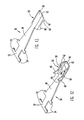
- Each extractor 32 shown in Figures 10 and 11 , includes an elongate strip body 38 extending between grip element 40 on one end of the body and cam end 42 on the opposite end of the body.
- the grip element 40 extends out from one side of body 38 and includes a number of closely spaced grip edges or corners 44 extending along a diagonal side of the grip element.
- the edges 44 face down toward recess 12 and facilitate manual engagement of the elements 40 and moving of the extractors 32 away from recess 12 to unlatch and remove the module from base 14, as described below.
- Spring pocket 46 is provided on strip body 38. When assemblies 30 are mounted in module 10, grip elements 40 extend outwardly from the edges of the module and pockets 46 extend inwardly toward the interior of the module. The recesses in spring pockets 46 face the upper ends of strip bodies 38 and grip elements 40.
- Latch member 36 shown in Figures 12 and 13 , is formed from flat, uniform-thickness strip metal and includes an elongate, tapered-width spring arm 48, a channel-shaped shift member 50 at the narrow lower end of arm 48 and a mounting member 52 at the wide upper end of arm 48.
- the width of arm 48 is tapered to reduce stress concentration.
- Mounting member 52 includes pairs of mounting ribs 54 extending to either side of spring arm 48.
- Stiff channel-shaped shift member 50 includes a flat base 56 forming an extension of spring arm 48 and opposed sides 58 bent up 90 degrees to base 56 and extending upwardly from one side of the base.
- Angled follower arms 60 extend above sides 58 and are adjacent spring arm 48.
- Angled latch arms 62 extend above sides or sidewalls 58 and are on the end of shift member 50 away from arm 48. The angled edges of arms 60 and 62 face down, away from spring arm 48.
- Latching surfaces 64 on arms 62 face up toward spring arm 48 and are undercut to improve latching engagement with complementary, angled latch surface 66 on an inner side of base wall 74 at the bottom of recess 12, as shown in Figure 6 .
- the two latch extractor assemblies 30 are identical. Each assembly is mounted on one edge of module body 18. Mounting of an assembly 30 on the right edge of the module shown in Figure 3 will now be described, it being understood that the latch extractor assembly on the left edge of the module is similarly mounted on the module.
- Latch member 36 is positioned in one open shell 20 by extending the mounting ribs 54 on one side of member 36 into recesses 70 in the shell with the arm 48 and shift member 50 extending freely in an interior channel 72 in the shell 20. See Figure 8 .
- the free end of shift member 50 and latch arms 62 extend through opening 76 in module bottom wall 79.
- the adjacent faces of the pairs of ribs 54 in recesses 70 have tight fits with the adjacent walls of recesses 70 to locate member 36 accurately in channel 72.
- Extractor 32 is fitted in an elongate groove 78 extending along the side of the shell 20 holding the latch member 36.
- Strip body 38 is freely movable along the groove.
- Spring pocket 46 extends into recess 80 formed on the inner side of groove 78 with compressed spring 34 extending from the bottom of the pocket to the slotted upper wall 82 of the recess. Wall 82 is slotted to accommodate a tool holding spring 34 compressed in pocket 46 during installation of the extractor and spring into the groove 78 and recess 80.
- Groove 78 extends from wall 79 at the lower end of the shell to step 84 adjacent the upper end of the shell.
- Spring 34 normally holds extractor 32 in a down position, shown in Figure 3 , with the lower end 81 of the extractor on wall 79. See Figure 6 .
- Grip element 40 is normally located immediately above step 84 when extractor 32 is held in the down position shown in Figure 3 by spring 34.
- the second shell With the extractors 32 and metal latch members 36 positioned in one shell, and electronic component 26 and connector 28 positioned in the shell, the second shell is positioned over the first shell, and the two shells are moved together so that the adjacent edges of the shells abut each other.
- the shells include post and recess latches on their abutting edges. The latches secure the two shells together to form body 18 with the latch extractor assemblies, electronic component and connector held in place in body 18.
- each extractor 32 has two angled cam surfaces 86.
- Surfaces 86 are on opposed sides of cam end 42.
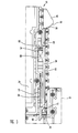
- the cam surfaces 86 immediately engage angled follower arms 60 on shift members 50 to immediately flex the adjacent spring arms 48 inwardly and move members 50 from latched positions adjacent the outer side of the module, shown in Figures 3 and 6 , to unlatched positions inwardly from the outer edges of the module, shown in Figures 4 and 7 .
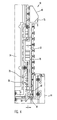
- Springs 34 are compressed and ends 81 are raised above wall 79. Spring arms 48 bias the channel members toward the latched position. Upward movement of grip elements 40 short distance 75, shown in Figure 4 , moves cam ends 42 into engagement with shift members 50 to cam members 50 inwardly, away from the adjacent sides of the module, to the unlatched or released position shown in Figures 4 and 7 .
- Assembled module 10 is latched into base 14 by extending the lower end of the module into recess 12.
- Lead ends 92 of shift members 50 are piloted into latch openings 68 formed through base wall 74.
- the angled surfaces of latch arms 62 engage the outer edges of openings 68 so that the members 50 are moved inwardly and arms 48 are flexed inwardly in channels 72 until arms 62 pass through the openings 68 and the flexed spring arms 48 move outwardly to move the latch arms 62 outwardly and under latch surfaces 66 to the latched position shown in Figures 3 and 6 .
- Connector 28 engages the connector on base 14.
- the arms 48 are flexed to move shift members 50 through openings 68 and to the latched positions.
- the extractors 32 are not used to latch the module to the base.
- cam ends 42 In order to remove a latched module from the base, an operator pulls the undersurfaces of grip elements 40 up a short distance 75 away from base 14. The edges 44 improve the operator's grip of elements 40.
- the initial upward movement of the grip elements 40 pulls cam ends 42 up from the position of Figure 6 to the position of Figure 7 .
- Cam surfaces 86 on the opposite edges of cam ends 42 are brought immediately into engagement with the angled follower surfaces on arms 60 located on the outer sides of the upper end of shift member 50.
- Cam ends 42 are supported against outward movement by raised ribs 88 which are located centrally on the ends, equidistant between the two cam surfaces 86.
- Upward movement of cam ends 42 rotates shift member 50 inwardly and flexes spring arm 48 inwardly to move latch arms 62 inwardly a distance beyond latch surface 66 to unlatch the module from the base.
- ribs 88 on cam ends 42 engage the outer walls of grooves 78.
- the ribs 88 are located between the two laterally spaced cam surfaces 86, in the center of cam end 42, to support the surfaces during inward camming of shift members 50 and prevent twisting of ends 42 and members 50.
- the ribs 88 also space the outer surfaces 98 of strip bodies 38 from the adjacent walls of grooves 78 to reduce friction during unlatching.
- Metal shift member 50 with flat base 56 and upstanding channel sides 58 has a channel-shaped cross-section and is very stiff.
- the stiffness of the member prevents bending of the member during unlatching when forces exerted by the cam end 42 of extractor 32 on the spaced follower arms 60 are transmitted along the length of the member 50 to move latch arms 62 on the bottom of the channel member laterally inwardly and unlatch the module.
- each member 50 directly transmits unlatching forces along each L-shaped side of member 50 from an arm 60 to an arm 62 to move arms 62 inwardly away from the angled latch surfaces 66 on the bottom of the base without bending.
- the lateral stiffness of the channel-shaped metal shift member 50 assures that the member is not deformed laterally despite location of arms 60 outside of rib 88.
- cam end 42 of extractor 32 and shift member 50 of latch member 36 are fitted together in alignment with follower arms 60 on member 50 extending into recesses 100 formed in the sides of cam end 42.
Landscapes
- Engineering & Computer Science (AREA)
- Automation & Control Theory (AREA)
- Microelectronics & Electronic Packaging (AREA)
- Mounting Components In General For Electric Apparatus (AREA)
- Details Of Connecting Devices For Male And Female Coupling (AREA)
- Casings For Electric Apparatus (AREA)
- Mounting Of Printed Circuit Boards And The Like (AREA)
Abstract
Description
- The field of the invention relates to an electronic module which is removably mounted on a base. During mounting, the module is latched to the base and electrical connections are established between an electronic component in the module and the base.
- The invention is an improved latch and extractor for removably mounting an electronic module on a base. The latch and extractor includes spring latches which engage the base when the module is pushed into the base. The module is easily unlatched and removed from the base by pulling upwardly on opposed grip elements to unlatch the module from the base. The module is unlatched by short initial upward movement of the grip elements relative to the module. After unlatching, further upward movement of the grip elements removes the module from the base. After removal of the module, the grip elements automatically return to their initial positions.
- The grip elements are on extractors which engage latch members holding the module on the base. The latch members have stiff shift member lower ends. The shift members transmit unlatching forces from the extractors to the latch arms engaging the base without bending to shift the arms from latched positions to unlatched positions in response to small initial upward movement of the grip elements. The shift members are channel-shaped and transmit unlatching forces without bending.
-
-
Figure 1 is a side view of an electronic module mounted on a base; -
Figure 2 is a top view ofFigure 1 ; -
Figure 3 is a vertical sectional view taken along through one side of the module illustrating a latch and extractor assembly in the latched position; -
Figure 4 is likeFigure 3 with the assembly in the unlatched position; -
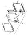
Figure 5 is an exploded view of the module; -
Figures 6 and7 are enlarged views of portions ofFigures 4 and5 showing the latched and unlatched positions of the assembly; -
Figure 8 is a sectional view along line 8--8 ofFigure 4 ; -
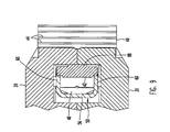
Figure 9 is a sectional view through the module along line 9--9 ofFigure 7 ; -
Figures 10 and 11 are perspective views of both sides of an extractor; and -
Figures 12 and 13 are perspective views of both sides of a latch member. -
Electronic module 10 is removably mounted inrecess 12 onbase 14 which is typically mounted onDIN rail 16. Themodule 10 includesbody 18 formed by two hollow moldedplastic shells 20 joined together at acircumferential seam 22 defining a hollowinterior cavity 24. An electronic component 26 is mounted incavity 24 and includes an electrical connector 28 which forms electrical connections with a complementary electrical connector (not illustrated) positioned in an opening in the bottom ofrecess 12 when the module is inserted into the recess, as shown inFigure 1 . -
Base 14 may be a power supply base for a process fieldbus. The electronic component 26 inmodule 10 may be a power supply device which regulates the voltage of DC power supplied to a process fieldbus connected to the base despite variation in the voltage of the power supplied to the module. Other types of electronic components may be mounted in themodule 10. The module may be mounted on other types of bases. - The
module 10 is removably mounted onbase 14 by two likelatch extractor assemblies 30 located on opposed edges of the module. Eachassembly 30 includes a moldedplastic extractor 32, returncoil spring 34 andmetal latch member 36. Eachextractor 32, shown inFigures 10 and 11 , includes anelongate strip body 38 extending betweengrip element 40 on one end of the body andcam end 42 on the opposite end of the body. Thegrip element 40 extends out from one side ofbody 38 and includes a number of closely spaced grip edges orcorners 44 extending along a diagonal side of the grip element. Theedges 44 face down towardrecess 12 and facilitate manual engagement of theelements 40 and moving of theextractors 32 away fromrecess 12 to unlatch and remove the module frombase 14, as described below. -
Spring pocket 46 is provided onstrip body 38. Whenassemblies 30 are mounted inmodule 10,grip elements 40 extend outwardly from the edges of the module andpockets 46 extend inwardly toward the interior of the module. The recesses inspring pockets 46 face the upper ends ofstrip bodies 38 andgrip elements 40. - Latch
member 36, shown inFigures 12 and 13 , is formed from flat, uniform-thickness strip metal and includes an elongate, tapered-width spring arm 48, a channel-shaped shift member 50 at the narrow lower end ofarm 48 and amounting member 52 at the wide upper end ofarm 48. The width ofarm 48 is tapered to reduce stress concentration.Mounting member 52 includes pairs ofmounting ribs 54 extending to either side ofspring arm 48. - Stiff channel-
shaped shift member 50 includes aflat base 56 forming an extension ofspring arm 48 and opposedsides 58 bent up 90 degrees tobase 56 and extending upwardly from one side of the base.Angled follower arms 60 extend abovesides 58 and areadjacent spring arm 48. Angledlatch arms 62 extend above sides orsidewalls 58 and are on the end ofshift member 50 away fromarm 48. The angled edges ofarms spring arm 48. -
Latching surfaces 64 onarms 62 face up towardspring arm 48 and are undercut to improve latching engagement with complementary,angled latch surface 66 on an inner side ofbase wall 74 at the bottom ofrecess 12, as shown inFigure 6 . - The two
latch extractor assemblies 30 are identical. Each assembly is mounted on one edge ofmodule body 18. Mounting of anassembly 30 on the right edge of the module shown inFigure 3 will now be described, it being understood that the latch extractor assembly on the left edge of the module is similarly mounted on the module. - Latch
member 36 is positioned in oneopen shell 20 by extending themounting ribs 54 on one side ofmember 36 into recesses 70 in the shell with thearm 48 andshift member 50 extending freely in aninterior channel 72 in theshell 20. SeeFigure 8 . The free end ofshift member 50 andlatch arms 62 extend through opening 76 inmodule bottom wall 79. The adjacent faces of the pairs ofribs 54 in recesses 70 have tight fits with the adjacent walls of recesses 70 to locatemember 36 accurately inchannel 72. -
Extractor 32 is fitted in anelongate groove 78 extending along the side of theshell 20 holding thelatch member 36.Strip body 38 is freely movable along the groove.Spring pocket 46 extends intorecess 80 formed on the inner side ofgroove 78 withcompressed spring 34 extending from the bottom of the pocket to the slottedupper wall 82 of the recess.Wall 82 is slotted to accommodate atool holding spring 34 compressed inpocket 46 during installation of the extractor and spring into thegroove 78 and recess 80. Groove 78 extends fromwall 79 at the lower end of the shell tostep 84 adjacent the upper end of the shell.Spring 34 normally holdsextractor 32 in a down position, shown inFigure 3 , with thelower end 81 of the extractor onwall 79. SeeFigure 6 .Grip element 40 is normally located immediately abovestep 84 whenextractor 32 is held in the down position shown inFigure 3 byspring 34. - With the
extractors 32 andmetal latch members 36 positioned in one shell, and electronic component 26 and connector 28 positioned in the shell, the second shell is positioned over the first shell, and the two shells are moved together so that the adjacent edges of the shells abut each other. The shells include post and recess latches on their abutting edges. The latches secure the two shells together to formbody 18 with the latch extractor assemblies, electronic component and connector held in place inbody 18. - The
cam end 42 of eachextractor 32 has two angled cam surfaces 86.Surfaces 86 are on opposed sides ofcam end 42. Whengrip elements 40 are pulled up, the cam surfaces 86 immediately engageangled follower arms 60 onshift members 50 to immediately flex theadjacent spring arms 48 inwardly and movemembers 50 from latched positions adjacent the outer side of the module, shown inFigures 3 and6 , to unlatched positions inwardly from the outer edges of the module, shown inFigures 4 and7 .Springs 34 are compressed and ends 81 are raised abovewall 79.Spring arms 48 bias the channel members toward the latched position. Upward movement ofgrip elements 40short distance 75, shown inFigure 4 , moves cam ends 42 into engagement withshift members 50 tocam members 50 inwardly, away from the adjacent sides of the module, to the unlatched or released position shown inFigures 4 and7 . -
Assembled module 10 is latched intobase 14 by extending the lower end of the module intorecess 12. Lead ends 92 ofshift members 50 are piloted intolatch openings 68 formed throughbase wall 74. The angled surfaces oflatch arms 62 engage the outer edges ofopenings 68 so that themembers 50 are moved inwardly andarms 48 are flexed inwardly inchannels 72 untilarms 62 pass through theopenings 68 and the flexedspring arms 48 move outwardly to move thelatch arms 62 outwardly and under latch surfaces 66 to the latched position shown inFigures 3 and6 . During latching of the module onto the base, the top of the module is pushed into the recess. Connector 28 engages the connector onbase 14. Thearms 48 are flexed to moveshift members 50 throughopenings 68 and to the latched positions. Theextractors 32 are not used to latch the module to the base. - In order to remove a latched module from the base, an operator pulls the undersurfaces of
grip elements 40 up ashort distance 75 away frombase 14. Theedges 44 improve the operator's grip ofelements 40. The initial upward movement of thegrip elements 40 pulls cam ends 42 up from the position ofFigure 6 to the position ofFigure 7 . Cam surfaces 86 on the opposite edges of cam ends 42 are brought immediately into engagement with the angled follower surfaces onarms 60 located on the outer sides of the upper end ofshift member 50. Cam ends 42 are supported against outward movement by raisedribs 88 which are located centrally on the ends, equidistant between the two cam surfaces 86. Upward movement of cam ends 42 rotates shiftmember 50 inwardly and flexesspring arm 48 inwardly to movelatch arms 62 inwardly a distance beyondlatch surface 66 to unlatch the module from the base. - Upward movement of
grip elements 40 simultaneously unlatches the twomembers 50 from basebottom wall 74 and, with further upward movement, withdraws the unlatched module from the base recess and disengages the connectors. - During unlatching of the module,
ribs 88 on cam ends 42 engage the outer walls ofgrooves 78. Theribs 88 are located between the two laterally spaced cam surfaces 86, in the center ofcam end 42, to support the surfaces during inward camming ofshift members 50 and prevent twisting ofends 42 andmembers 50. Theribs 88 also space theouter surfaces 98 ofstrip bodies 38 from the adjacent walls ofgrooves 78 to reduce friction during unlatching. -
Metal shift member 50, withflat base 56 and upstanding channel sides 58 has a channel-shaped cross-section and is very stiff. The stiffness of the member prevents bending of the member during unlatching when forces exerted by thecam end 42 ofextractor 32 on the spacedfollower arms 60 are transmitted along the length of themember 50 to movelatch arms 62 on the bottom of the channel member laterally inwardly and unlatch the module. During unlatching eachmember 50 directly transmits unlatching forces along each L-shaped side ofmember 50 from anarm 60 to anarm 62 to movearms 62 inwardly away from the angled latch surfaces 66 on the bottom of the base without bending. The lateral stiffness of the channel-shapedmetal shift member 50 assures that the member is not deformed laterally despite location ofarms 60 outside ofrib 88. - The
cam end 42 ofextractor 32 andshift member 50 oflatch member 36 are fitted together in alignment withfollower arms 60 onmember 50 extending intorecesses 100 formed in the sides ofcam end 42.
Claims (14)
- An electronic module comprising a module body and a first latch extractor assembly for removably mounting the module body on a support member, the latch extractor assembly including a metal latch member having an elongate spring arm, a mounting portion at one end of the spring arm, and a shift member at the other end of the spring arm, said mounting portion secured to the module body, the shift member including a generally flat base and a first base sidewall extending up from the base at an angle of about 90 degrees so that the shift member is L-shaped and rigid, a first latch arm on the first base sidewall away from the spring arm, a first follower arm on the first base sidewall adjacent the spring arm; and an extractor having an elongate extractor body, a grip element at one end of the extractor body and a first cam surface at the other end of the extractor body, the cam surface engaging the first follower arm; whereby movement of the grip element moves the cam surface along the follower arm to cam the shift member laterally and move the latch arm out of engagement with a support member, the shift member transmitting forces from the follower arm to the latch arm without bending.
- The module as in claim 1 including a spring biasing the extractor to move the cam surface away from the follower arm.
- The module as in claim 1 wherein the spring arm is flat and tapered.
- The module as in claim 1 wherein the shift member includes a second base sidewall, a second latch arm on the second base sidewall and a second follower arm on the second base sidewall; and the extractor includes a second cam surface engageable with the second follower arm.
- The module as in claim 1 wherein the latch extractor assembly is located on a first module edge.
- The module as in claim 1 wherein the first latch arm is located outside the module and the first follower arm and the cam surface are located inside the module.
- The module as in claim 1 wherein the extractor body extends to one side of said spring arm and is located between the spring arm and the outer surface of the module, and the grip element is located on the outside of the module body above the metal latch member.
- The module as in claim 1 wherein the shift member includes a second base sidewall and a second follower arm on said second base sidewall; and the extractor includes a second cam surface engageable with the second follower arm.
- The module as in claim 8 wherein the extractor includes a pad located away from the shift member, the pad between the first and second cam surfaces, said pad engaging a surface of the module, wherein the pad spaces the extractor body from the module to reduce friction and support the shift member.
- The module as in claim 1 including an electronic component in the module body and an electrical connector attached to the component for forming electrical connections with a complementary electrical connector.
- An electronic module comprising a module body, a power supply device for regulating the voltage of DC power supplied to a process fieldbus, an electrical connector joined to the power supply device, the power supply device mounted in the body; a first latch extractor assembly for removably mounting the module on a power supply base for a process fieldbus, the latch extractor assembly including a metal latch member having an elongate spring arm, a mounting portion at one end of the spring arm and a shift member at the other end of the spring arm, said mounting portion secured to the module body, the shift member adjacent the power supply base and including a shift member base, first and second base sidewalls extending up from opposed sides of the base at about 90 degrees so that the shift member is generally channel-shaped, first and second latch arms on the base sidewalls away from the spring arm, first and second follower arms on the base sidewalls adjacent the spring arm; and an extractor having an elongate extractor body, a grip element at one end of the extractor body away from the power supply base and first and second cam surfaces on the other end of the extractor body adjacent the shift member, the cam surfaces engaging the follower arms; whereby movement of the grip element moves the cam surfaces along the follower arms to cam the shift member laterally and move the latch arms out of engagement with a power supply base, the shift member transmitting forces from the follower arms to the latch arms without bending.
- The module as in claim 11 including a pad on the extractor between the same cam surfaces and away from the shift member, the pad engaging a surface of the module to space the extractor body from the module and support the shift member.
- The module as in claim 11 wherein the latch arms are located outside the module.
- The module as in claim 11 including a spring mounted between the module body and the extractor, such spring biasing the cam surfaces away from the follower arms.
Applications Claiming Priority (1)
| Application Number | Priority Date | Filing Date | Title |
|---|---|---|---|
| US13/069,676 US8123545B1 (en) | 2011-03-23 | 2011-03-23 | Latch and extractor for electronic module |
Publications (3)
| Publication Number | Publication Date |
|---|---|
| EP2503864A2 true EP2503864A2 (en) | 2012-09-26 |
| EP2503864A3 EP2503864A3 (en) | 2015-03-04 |
| EP2503864B1 EP2503864B1 (en) | 2018-10-10 |
Family
ID=45694420
Family Applications (1)
| Application Number | Title | Priority Date | Filing Date |
|---|---|---|---|
| EP12002034.2A Not-in-force EP2503864B1 (en) | 2011-03-23 | 2012-03-22 | Latch and extractor for electronic module |
Country Status (5)
| Country | Link |
|---|---|
| US (2) | US8123545B1 (en) |
| EP (1) | EP2503864B1 (en) |
| JP (1) | JP5933304B2 (en) |
| CN (1) | CN102695394B (en) |
| ES (1) | ES2699744T3 (en) |
Cited By (3)
| Publication number | Priority date | Publication date | Assignee | Title |
|---|---|---|---|---|
| EP3061327B1 (en) | 2013-10-21 | 2018-06-27 | Wago Verwaltungsgesellschaft mbH | Electronic device |
| DE102019126628A1 (en) * | 2019-10-02 | 2021-04-08 | Phoenix Contact Gmbh & Co. Kg | Electrical device with a locking device |
| DE102012213281B4 (en) | 2012-07-27 | 2024-06-06 | Phoenix Contact Gmbh & Co. Kg | Fieldbus modular system, carrier module and fieldbus module |
Families Citing this family (4)
| Publication number | Priority date | Publication date | Assignee | Title |
|---|---|---|---|---|
| JP2706814B2 (en) | 1989-05-29 | 1998-01-28 | 東海ゴム工業株式会社 | Rubber laminate |
| US9727098B2 (en) * | 2014-06-16 | 2017-08-08 | Phoenix Contact Development and Manufacturing, Inc. | Redundant power supply motherboard assembly |
| DE102015002389A1 (en) * | 2015-02-25 | 2016-08-25 | Abb Technology Ag | Modular field device connection unit |
| WO2019113003A1 (en) * | 2017-12-04 | 2019-06-13 | Electrix, Llc | Track lighting and accessory system |
Family Cites Families (18)
| Publication number | Priority date | Publication date | Assignee | Title |
|---|---|---|---|---|
| US5199897A (en) * | 1990-03-15 | 1993-04-06 | Japan Aviation Electronics Industry, Ltd. | Electrical connectors |
| JPH0630802U (en) * | 1992-09-11 | 1994-04-22 | 光洋電子工業株式会社 | Connection structure between PC units |
| EP1137115A3 (en) * | 2000-01-25 | 2002-04-10 | AMPHENOL-TUCHEL ELECTRONICS GmbH | Electrical plug |
| CN2641696Y (en) * | 2003-09-01 | 2004-09-15 | 广达电脑股份有限公司 | Integrated buckle lock |
| DE202004007909U1 (en) | 2004-05-17 | 2004-07-22 | Rosenberger Hochfrequenztechnik Gmbh & Co | Housing coupler for a coaxial connector |
| DE102005005914A1 (en) | 2005-02-09 | 2006-08-10 | Dehn + Söhne Gmbh + Co. Kg | Plug-in device combination for protection against overvoltages |
| DE102006033274A1 (en) | 2005-02-09 | 2008-01-31 | Dehn + Söhne Gmbh + Co. Kg | Plug-in device combination for protection against overvoltages |
| US7134914B1 (en) | 2005-08-11 | 2006-11-14 | Hon Hai Precision Ind. Co., Ltd. | Cable connector assembly with latching mechanism |
| US7175465B1 (en) * | 2005-08-26 | 2007-02-13 | Advanced Connectex Inc. | Electrical connector with a spring push button for disengagement with jack |
| DE102006034164B4 (en) | 2006-05-09 | 2008-07-31 | Dehn + Söhne Gmbh + Co. Kg | Multipole lightning current and / or surge arrester in terminal block design |
| US7341472B2 (en) | 2006-06-16 | 2008-03-11 | Cheng Uei Precision Industry Co., Ltd. | Plug connector with latch means |
| JP2009543296A (en) | 2006-06-30 | 2009-12-03 | モレックス インコーポレイテド | Low profile latch connector and pull tab for unlatching |
| US7429185B1 (en) * | 2007-08-31 | 2008-09-30 | Hon Hai Precision Ind. Co., Ltd. | Plug-in module with latch mechanism |
| JP2009123450A (en) * | 2007-11-14 | 2009-06-04 | Molex Inc | Latch connector |
| US20090246999A1 (en) * | 2008-03-27 | 2009-10-01 | Crofoot Larry M | Electrical connector latch with spring |
| JP5080336B2 (en) * | 2008-04-04 | 2012-11-21 | 日本航空電子工業株式会社 | Board mounting connector |
| US8092246B1 (en) * | 2008-04-18 | 2012-01-10 | Lockheed Martin Corporation | Self-locking micro-D connector |
| EP2351160B1 (en) * | 2008-10-15 | 2014-01-01 | Fci | Latch assembly for a connector |
-
2011
- 2011-03-23 US US13/069,676 patent/US8123545B1/en active Active
-
2012
- 2012-02-03 US US13/365,344 patent/US9065208B2/en active Active
- 2012-03-22 JP JP2012064979A patent/JP5933304B2/en not_active Expired - Fee Related
- 2012-03-22 ES ES12002034T patent/ES2699744T3/en active Active
- 2012-03-22 EP EP12002034.2A patent/EP2503864B1/en not_active Not-in-force
- 2012-03-23 CN CN201210093058.6A patent/CN102695394B/en not_active Expired - Fee Related
Non-Patent Citations (1)
| Title |
|---|
| None |
Cited By (5)
| Publication number | Priority date | Publication date | Assignee | Title |
|---|---|---|---|---|
| DE102012213281B4 (en) | 2012-07-27 | 2024-06-06 | Phoenix Contact Gmbh & Co. Kg | Fieldbus modular system, carrier module and fieldbus module |
| EP3061327B1 (en) | 2013-10-21 | 2018-06-27 | Wago Verwaltungsgesellschaft mbH | Electronic device |
| DE102019126628A1 (en) * | 2019-10-02 | 2021-04-08 | Phoenix Contact Gmbh & Co. Kg | Electrical device with a locking device |
| DE102019126628B4 (en) * | 2019-10-02 | 2021-06-10 | Phoenix Contact Gmbh & Co. Kg | Electrical device with a locking device |
| US12082358B2 (en) | 2019-10-02 | 2024-09-03 | Phoenix Contact Gmbh & Co. Kg | Electrical device having a locking device |
Also Published As
| Publication number | Publication date |
|---|---|
| US9065208B2 (en) | 2015-06-23 |
| US8123545B1 (en) | 2012-02-28 |
| EP2503864B1 (en) | 2018-10-10 |
| CN102695394B (en) | 2015-12-02 |
| JP5933304B2 (en) | 2016-06-08 |
| EP2503864A3 (en) | 2015-03-04 |
| ES2699744T3 (en) | 2019-02-12 |
| US20140109401A1 (en) | 2014-04-24 |
| JP2012203909A (en) | 2012-10-22 |
| CN102695394A (en) | 2012-09-26 |
Similar Documents
| Publication | Publication Date | Title |
|---|---|---|
| EP2503864B1 (en) | Latch and extractor for electronic module | |
| CN102695397B (en) | For power source base being installed to locking assembly on DIN guide rail and method | |
| US8926355B2 (en) | Connector position assurance device for a connector assembly | |
| US9509066B2 (en) | Connector | |
| JP7090584B2 (en) | Connector housing and terminal position guarantee joint clip site | |
| KR101342165B1 (en) | connector assembly | |
| US10333114B2 (en) | Energy storage apparatus | |
| EP1898498A2 (en) | Electrical Connector | |
| JP2013500598A (en) | Housing with lock structure | |
| KR101396303B1 (en) | Connector assembly | |
| WO2016084587A1 (en) | Connector | |
| CN108352644B (en) | Connector | |
| CN103608981A (en) | Lever mechanism for connector fitting, and connector | |
| US10033129B2 (en) | Connector | |
| JP2014521232A (en) | Retaining base design for instruments on cover removal instruments | |
| WO2015177959A1 (en) | Rail attachment apparatus for electrical device | |
| JP5144404B2 (en) | Connector housing | |
| US20120148893A1 (en) | Computer enclosure with battery holding structure | |
| KR20100022841A (en) | connector | |
| WO2015033828A1 (en) | Component detachment tool | |
| JP6256276B2 (en) | connector | |
| CN210111181U (en) | Unlocking device for Industrial Ethernet connectors | |
| KR200428003Y1 (en) | Connector assembly | |
| JP2013016399A (en) | Connector | |
| KR20100011826A (en) | Connector assembly having rework device |
Legal Events
| Date | Code | Title | Description |
|---|---|---|---|
| PUAI | Public reference made under article 153(3) epc to a published international application that has entered the european phase |
Free format text: ORIGINAL CODE: 0009012 |
|
| AK | Designated contracting states |
Kind code of ref document: A2 Designated state(s): AL AT BE BG CH CY CZ DE DK EE ES FI FR GB GR HR HU IE IS IT LI LT LU LV MC MK MT NL NO PL PT RO RS SE SI SK SM TR |
|
| AX | Request for extension of the european patent |
Extension state: BA ME |
|
| RIN1 | Information on inventor provided before grant (corrected) |
Inventor name: BARBER, TERRY LEE Inventor name: CORRELL, MICHAEL ANTHONY |
|
| RAP1 | Party data changed (applicant data changed or rights of an application transferred) |
Owner name: PHOENIX CONTACT GMBH & CO. KG |
|
| PUAL | Search report despatched |
Free format text: ORIGINAL CODE: 0009013 |
|
| AK | Designated contracting states |
Kind code of ref document: A3 Designated state(s): AL AT BE BG CH CY CZ DE DK EE ES FI FR GB GR HR HU IE IS IT LI LT LU LV MC MK MT NL NO PL PT RO RS SE SI SK SM TR |
|
| AX | Request for extension of the european patent |
Extension state: BA ME |
|
| RIC1 | Information provided on ipc code assigned before grant |
Ipc: H01R 9/26 20060101ALI20150126BHEP Ipc: H05K 7/14 20060101AFI20150126BHEP Ipc: H01R 13/627 20060101ALI20150126BHEP |
|
| 17P | Request for examination filed |
Effective date: 20150826 |
|
| RBV | Designated contracting states (corrected) |
Designated state(s): AL AT BE BG CH CY CZ DE DK EE ES FI FR GB GR HR HU IE IS IT LI LT LU LV MC MK MT NL NO PL PT RO RS SE SI SK SM TR |
|
| GRAP | Despatch of communication of intention to grant a patent |
Free format text: ORIGINAL CODE: EPIDOSNIGR1 |
|
| STAA | Information on the status of an ep patent application or granted ep patent |
Free format text: STATUS: GRANT OF PATENT IS INTENDED |
|
| INTG | Intention to grant announced |
Effective date: 20180511 |
|
| GRAS | Grant fee paid |
Free format text: ORIGINAL CODE: EPIDOSNIGR3 |
|
| GRAA | (expected) grant |
Free format text: ORIGINAL CODE: 0009210 |
|
| STAA | Information on the status of an ep patent application or granted ep patent |
Free format text: STATUS: THE PATENT HAS BEEN GRANTED |
|
| AK | Designated contracting states |
Kind code of ref document: B1 Designated state(s): AL AT BE BG CH CY CZ DE DK EE ES FI FR GB GR HR HU IE IS IT LI LT LU LV MC MK MT NL NO PL PT RO RS SE SI SK SM TR |
|
| REG | Reference to a national code |
Ref country code: GB Ref legal event code: FG4D |
|
| REG | Reference to a national code |
Ref country code: CH Ref legal event code: EP Ref country code: AT Ref legal event code: REF Ref document number: 1052819 Country of ref document: AT Kind code of ref document: T Effective date: 20181015 |
|
| REG | Reference to a national code |
Ref country code: IE Ref legal event code: FG4D |
|
| REG | Reference to a national code |
Ref country code: DE Ref legal event code: R096 Ref document number: 602012051934 Country of ref document: DE |
|
| REG | Reference to a national code |
Ref country code: ES Ref legal event code: FG2A Ref document number: 2699744 Country of ref document: ES Kind code of ref document: T3 Effective date: 20190212 |
|
| REG | Reference to a national code |
Ref country code: NL Ref legal event code: MP Effective date: 20181010 |
|
| REG | Reference to a national code |
Ref country code: LT Ref legal event code: MG4D |
|
| REG | Reference to a national code |
Ref country code: AT Ref legal event code: MK05 Ref document number: 1052819 Country of ref document: AT Kind code of ref document: T Effective date: 20181010 |
|
| PG25 | Lapsed in a contracting state [announced via postgrant information from national office to epo] |
Ref country code: NL Free format text: LAPSE BECAUSE OF FAILURE TO SUBMIT A TRANSLATION OF THE DESCRIPTION OR TO PAY THE FEE WITHIN THE PRESCRIBED TIME-LIMIT Effective date: 20181010 |
|
| PG25 | Lapsed in a contracting state [announced via postgrant information from national office to epo] |
Ref country code: BG Free format text: LAPSE BECAUSE OF FAILURE TO SUBMIT A TRANSLATION OF THE DESCRIPTION OR TO PAY THE FEE WITHIN THE PRESCRIBED TIME-LIMIT Effective date: 20190110 Ref country code: PL Free format text: LAPSE BECAUSE OF FAILURE TO SUBMIT A TRANSLATION OF THE DESCRIPTION OR TO PAY THE FEE WITHIN THE PRESCRIBED TIME-LIMIT Effective date: 20181010 Ref country code: HR Free format text: LAPSE BECAUSE OF FAILURE TO SUBMIT A TRANSLATION OF THE DESCRIPTION OR TO PAY THE FEE WITHIN THE PRESCRIBED TIME-LIMIT Effective date: 20181010 Ref country code: FI Free format text: LAPSE BECAUSE OF FAILURE TO SUBMIT A TRANSLATION OF THE DESCRIPTION OR TO PAY THE FEE WITHIN THE PRESCRIBED TIME-LIMIT Effective date: 20181010 Ref country code: LT Free format text: LAPSE BECAUSE OF FAILURE TO SUBMIT A TRANSLATION OF THE DESCRIPTION OR TO PAY THE FEE WITHIN THE PRESCRIBED TIME-LIMIT Effective date: 20181010 Ref country code: LV Free format text: LAPSE BECAUSE OF FAILURE TO SUBMIT A TRANSLATION OF THE DESCRIPTION OR TO PAY THE FEE WITHIN THE PRESCRIBED TIME-LIMIT Effective date: 20181010 Ref country code: AT Free format text: LAPSE BECAUSE OF FAILURE TO SUBMIT A TRANSLATION OF THE DESCRIPTION OR TO PAY THE FEE WITHIN THE PRESCRIBED TIME-LIMIT Effective date: 20181010 Ref country code: IS Free format text: LAPSE BECAUSE OF FAILURE TO SUBMIT A TRANSLATION OF THE DESCRIPTION OR TO PAY THE FEE WITHIN THE PRESCRIBED TIME-LIMIT Effective date: 20190210 Ref country code: NO Free format text: LAPSE BECAUSE OF FAILURE TO SUBMIT A TRANSLATION OF THE DESCRIPTION OR TO PAY THE FEE WITHIN THE PRESCRIBED TIME-LIMIT Effective date: 20190110 |
|
| PG25 | Lapsed in a contracting state [announced via postgrant information from national office to epo] |
Ref country code: PT Free format text: LAPSE BECAUSE OF FAILURE TO SUBMIT A TRANSLATION OF THE DESCRIPTION OR TO PAY THE FEE WITHIN THE PRESCRIBED TIME-LIMIT Effective date: 20190210 Ref country code: GR Free format text: LAPSE BECAUSE OF FAILURE TO SUBMIT A TRANSLATION OF THE DESCRIPTION OR TO PAY THE FEE WITHIN THE PRESCRIBED TIME-LIMIT Effective date: 20190111 Ref country code: SE Free format text: LAPSE BECAUSE OF FAILURE TO SUBMIT A TRANSLATION OF THE DESCRIPTION OR TO PAY THE FEE WITHIN THE PRESCRIBED TIME-LIMIT Effective date: 20181010 Ref country code: RS Free format text: LAPSE BECAUSE OF FAILURE TO SUBMIT A TRANSLATION OF THE DESCRIPTION OR TO PAY THE FEE WITHIN THE PRESCRIBED TIME-LIMIT Effective date: 20181010 Ref country code: AL Free format text: LAPSE BECAUSE OF FAILURE TO SUBMIT A TRANSLATION OF THE DESCRIPTION OR TO PAY THE FEE WITHIN THE PRESCRIBED TIME-LIMIT Effective date: 20181010 |
|
| REG | Reference to a national code |
Ref country code: DE Ref legal event code: R097 Ref document number: 602012051934 Country of ref document: DE |
|
| PG25 | Lapsed in a contracting state [announced via postgrant information from national office to epo] |
Ref country code: DK Free format text: LAPSE BECAUSE OF FAILURE TO SUBMIT A TRANSLATION OF THE DESCRIPTION OR TO PAY THE FEE WITHIN THE PRESCRIBED TIME-LIMIT Effective date: 20181010 Ref country code: CZ Free format text: LAPSE BECAUSE OF FAILURE TO SUBMIT A TRANSLATION OF THE DESCRIPTION OR TO PAY THE FEE WITHIN THE PRESCRIBED TIME-LIMIT Effective date: 20181010 |
|
| PLBE | No opposition filed within time limit |
Free format text: ORIGINAL CODE: 0009261 |
|
| STAA | Information on the status of an ep patent application or granted ep patent |
Free format text: STATUS: NO OPPOSITION FILED WITHIN TIME LIMIT |
|
| PG25 | Lapsed in a contracting state [announced via postgrant information from national office to epo] |
Ref country code: SK Free format text: LAPSE BECAUSE OF FAILURE TO SUBMIT A TRANSLATION OF THE DESCRIPTION OR TO PAY THE FEE WITHIN THE PRESCRIBED TIME-LIMIT Effective date: 20181010 Ref country code: EE Free format text: LAPSE BECAUSE OF FAILURE TO SUBMIT A TRANSLATION OF THE DESCRIPTION OR TO PAY THE FEE WITHIN THE PRESCRIBED TIME-LIMIT Effective date: 20181010 Ref country code: SM Free format text: LAPSE BECAUSE OF FAILURE TO SUBMIT A TRANSLATION OF THE DESCRIPTION OR TO PAY THE FEE WITHIN THE PRESCRIBED TIME-LIMIT Effective date: 20181010 Ref country code: RO Free format text: LAPSE BECAUSE OF FAILURE TO SUBMIT A TRANSLATION OF THE DESCRIPTION OR TO PAY THE FEE WITHIN THE PRESCRIBED TIME-LIMIT Effective date: 20181010 |
|
| 26N | No opposition filed |
Effective date: 20190711 |
|
| PG25 | Lapsed in a contracting state [announced via postgrant information from national office to epo] |
Ref country code: MC Free format text: LAPSE BECAUSE OF FAILURE TO SUBMIT A TRANSLATION OF THE DESCRIPTION OR TO PAY THE FEE WITHIN THE PRESCRIBED TIME-LIMIT Effective date: 20181010 Ref country code: SI Free format text: LAPSE BECAUSE OF FAILURE TO SUBMIT A TRANSLATION OF THE DESCRIPTION OR TO PAY THE FEE WITHIN THE PRESCRIBED TIME-LIMIT Effective date: 20181010 |
|
| REG | Reference to a national code |
Ref country code: CH Ref legal event code: PL |
|
| PG25 | Lapsed in a contracting state [announced via postgrant information from national office to epo] |
Ref country code: LU Free format text: LAPSE BECAUSE OF NON-PAYMENT OF DUE FEES Effective date: 20190322 |
|
| REG | Reference to a national code |
Ref country code: BE Ref legal event code: MM Effective date: 20190331 |
|
| PG25 | Lapsed in a contracting state [announced via postgrant information from national office to epo] |
Ref country code: IE Free format text: LAPSE BECAUSE OF NON-PAYMENT OF DUE FEES Effective date: 20190322 Ref country code: LI Free format text: LAPSE BECAUSE OF NON-PAYMENT OF DUE FEES Effective date: 20190331 Ref country code: CH Free format text: LAPSE BECAUSE OF NON-PAYMENT OF DUE FEES Effective date: 20190331 |
|
| PG25 | Lapsed in a contracting state [announced via postgrant information from national office to epo] |
Ref country code: BE Free format text: LAPSE BECAUSE OF NON-PAYMENT OF DUE FEES Effective date: 20190331 |
|
| PG25 | Lapsed in a contracting state [announced via postgrant information from national office to epo] |
Ref country code: TR Free format text: LAPSE BECAUSE OF FAILURE TO SUBMIT A TRANSLATION OF THE DESCRIPTION OR TO PAY THE FEE WITHIN THE PRESCRIBED TIME-LIMIT Effective date: 20181010 |
|
| PG25 | Lapsed in a contracting state [announced via postgrant information from national office to epo] |
Ref country code: MT Free format text: LAPSE BECAUSE OF NON-PAYMENT OF DUE FEES Effective date: 20190322 |
|
| PG25 | Lapsed in a contracting state [announced via postgrant information from national office to epo] |
Ref country code: CY Free format text: LAPSE BECAUSE OF FAILURE TO SUBMIT A TRANSLATION OF THE DESCRIPTION OR TO PAY THE FEE WITHIN THE PRESCRIBED TIME-LIMIT Effective date: 20181010 |
|
| PG25 | Lapsed in a contracting state [announced via postgrant information from national office to epo] |
Ref country code: HU Free format text: LAPSE BECAUSE OF FAILURE TO SUBMIT A TRANSLATION OF THE DESCRIPTION OR TO PAY THE FEE WITHIN THE PRESCRIBED TIME-LIMIT; INVALID AB INITIO Effective date: 20120322 |
|
| PG25 | Lapsed in a contracting state [announced via postgrant information from national office to epo] |
Ref country code: MK Free format text: LAPSE BECAUSE OF FAILURE TO SUBMIT A TRANSLATION OF THE DESCRIPTION OR TO PAY THE FEE WITHIN THE PRESCRIBED TIME-LIMIT Effective date: 20181010 |
|
| P01 | Opt-out of the competence of the unified patent court (upc) registered |
Effective date: 20230424 |
|
| PGFP | Annual fee paid to national office [announced via postgrant information from national office to epo] |
Ref country code: GB Payment date: 20240319 Year of fee payment: 13 |
|
| PGFP | Annual fee paid to national office [announced via postgrant information from national office to epo] |
Ref country code: IT Payment date: 20240321 Year of fee payment: 13 Ref country code: FR Payment date: 20240326 Year of fee payment: 13 |
|
| PGFP | Annual fee paid to national office [announced via postgrant information from national office to epo] |
Ref country code: DE Payment date: 20240529 Year of fee payment: 13 |
|
| PGFP | Annual fee paid to national office [announced via postgrant information from national office to epo] |
Ref country code: ES Payment date: 20240412 Year of fee payment: 13 |
|
| REG | Reference to a national code |
Ref country code: DE Ref legal event code: R119 Ref document number: 602012051934 Country of ref document: DE |
|
| GBPC | Gb: european patent ceased through non-payment of renewal fee |
Effective date: 20250322 |
|
| PG25 | Lapsed in a contracting state [announced via postgrant information from national office to epo] |
Ref country code: DE Free format text: LAPSE BECAUSE OF NON-PAYMENT OF DUE FEES Effective date: 20251001 |
|
| PG25 | Lapsed in a contracting state [announced via postgrant information from national office to epo] |
Ref country code: GB Free format text: LAPSE BECAUSE OF NON-PAYMENT OF DUE FEES Effective date: 20250322 |
|
| PG25 | Lapsed in a contracting state [announced via postgrant information from national office to epo] |
Ref country code: IT Free format text: LAPSE BECAUSE OF NON-PAYMENT OF DUE FEES Effective date: 20250322 Ref country code: FR Free format text: LAPSE BECAUSE OF NON-PAYMENT OF DUE FEES Effective date: 20250331 |
|
| REG | Reference to a national code |
Ref country code: ES Ref legal event code: FD2A Effective date: 20260504 |